Abstract
Achieving vibration-free smooth motion of industrial robotic arms in a short period is an important research topic. Existing path planning algorithms often sacrifice smoothness in pursuit of efficient motion. A robotic trajectory planning particle swarm optimization algorithm (RTPPSO) is introduced for optimizing joint angles or paths of mechanical arm movements. The RTPPSO algorithm is enhanced through the introduction of adaptive weight strategies and random perturbation terms. Subsequently, the RTPPSO algorithm is utilized to plan selected parameters of an S-shaped velocity profile, iterating to obtain the optimal solution. Experimental results demonstrate that this velocity planning algorithm significantly improves the acceleration of the robotic arm, surpassing traditional trial-and-error velocity planning methods.
1. Introduction
The motion control of industrial manipulators typically involves a planning layer and a control layer. The former mainly focuses on understanding the relationship between the manipulator’s position, speed, and time to realize the operation. Meanwhile, the control layer addresses how to ensure the actuator effectively follows the planned trajectory. Therefore, trajectory planning consists of basic research in the field of manipulator control. This has an important impact on the working efficiency, motion stability, and energy consumption of the manipulator [1]. Optimal trajectory planning aims to devise the optimal trajectory through task points, considering the predefined execution task points and motion constraints. The general trajectory planning algorithm transforms the original path into an optimized trajectory by planning parameters, such as the position, velocity, and acceleration for each task point on the manipulator’s operational path. This enhances the accuracy and stability of the manipulator’s trajectory [2]. Therefore, the purpose of this paper is to control the speed and acceleration of the manipulator during operation, aiming to enhance stability and reduce the impact and wear of the manipulator.
In recent years, trajectory planning of industrial manipulators has been considered an important research focus in the field of robot control. Moreover, the research for a manipulator’s optimal path planning has also seen important progress. In more detail, interpolation algorithms consist of a common method in manipulator trajectory planning due to their advantages, including simple calculation and easy implementation [3,4,5]. For instance, Shi et al. [6] utilized an interpolation algorithm grounded in the forward-looking function to fine-tune the feed speed. This was achieved by predicting the future change in trajectory curvature. This approach not only ensured the precision of the interpolation algorithm but also enhanced processing efficiency. Moreover, Luo et al. [7] considered the use of a Lagrange interpolation function as the trajectory function for individual joints to optimize the energy consumption of an industrial manipulator and derive the optimal trajectory. In addition, Nadir et al. [8] used multiquadric radial basic functions to generate the manipulator’s motion trajectory through the minimization of the acceleration integral and the consideration of the boundary conditions and the kinematic limits. Compared to other methods, this algorithm has higher smoothness. However, its accuracy is affected by the number of interpolation functions and interpolation nodes; consequently, it may not be effective when dealing with complex trajectory curves.
Moreover, the swarm intelligent control algorithm is a heuristic algorithm developed to solve the motion path of a manipulator through the simulation of the swarm intelligent behavior in nature. This latter is characterized by its strong adaptability and ability to handle complex motion trajectory, including the genetic algorithm (GA) [9,10,11], the artificial immune algorithm [12], and the particle swarm optimization (PSO) algorithm [13,14].
The core idea of the PSO algorithm consists of finding the optimal solution of the problem by simulating the flock predation process and constantly adjusting the speed and position of the particles [15]. Compared to other similar algorithms, PSO has high efficiency, global optimization ability, adaptability, and expansibility. However, the traditional PSO algorithm is prone to premature convergence. Therefore, several researchers have improved the algorithm’s performance by adjusting relevant parameters and combining them with other intelligent algorithms. For instance, Lv et al. [16] proposed an improved PSO algorithm combining the fuzzy reward and punishment theory to resolve the manipulator’s trajectory planning problem when having multiple Degrees of Freedom (DoF). Therefore, the global search ability of the PSO algorithm is enhanced by adding a population exchange term, and the last elimination principle is applied to avoid falling into the local optimum. Moreover, Li et al. [17] adopted PSO as the optimizer algorithm to solve the vibration suppression problem of a flexible linkage manipulator and enhanced the efficiency and accuracy of trajectory planning. In addition, Du et al. [18] introduced chaotic sequence as a local search strategy in the PSO algorithm and employed a piecewise polynomial interpolation function to approximate the optimal trajectory. These improvements enhanced the search efficiency and optimization performance of the algorithm and were able to effectively shorten the running time of the manipulator. Moreover, they ensured the stability of the movement. Added to that, Yang et al. [19] introduced an innovative time optimization strategy, known as a Second-Order Continuous Polynomial Interpolation Function (SCPIF). This approach, coupled with the cosine subweighted PSO, addresses the challenge of time-optimal trajectory optimization.
Although the above research has made some achievements, there are still many shortcomings. Firstly, the existing particle swarm optimization algorithms [20,21] are often only applicable to specific types of problems; however, they lack universality in other categories. In addition, the performance of existing algorithms still depends on the choice of parameters, such as weight factors and inertia weights. Therefore, the optimal value needs to consider the actual situation of the industry. In the practical utilization process, in dealing with nonlinear optimization problems, the existing algorithms will fall into local optimal solutions, resulting in performance degradation.
As a result, considering the industrial requirements of the manipulator in practical application processes, as well as the limiting factors including the position, speed, and acceleration of each task point, a new control strategy with high speed and high stability is proposed to achieve the manipulator’s functional requirements. Moreover, the algorithm will be applied for transporting liquid reagents. It is worth noting that the proposed velocity optimal trajectory optimization strategy has a high stability level. Compared to other improved PSO algorithms, it is easily implemented and applicable to a variety of scenarios.
To sum up, the contributions of this paper are as follows:
- A new Robot Trajectory Planning Particle Swarm Optimization (RTPPSO) algorithm is proposed in this paper;
- The PSO algorithm is applied to the trajectory planning and parameter optimization for each robot manipulator joint.
2. Trajectory Planning
2.1. Overview of Trajectory Planning
Trajectory planning typically focuses on two research areas: mobile robots and industrial robots. In the context of the mobile robot, trajectory planning mainly refers to the path trajectory planning of the robot. For example, whether the robot has a map or not, the kind of path trajectory to follow is determined at this level. For industrial robots, trajectory planning encompasses two directions. Firstly, it involves planning the curvilinear trajectory of the end of the manipulator, detailing the curvilinear profile of the manipulator during motion displacement, velocity, and acceleration. As for the trajectory planning, it is also divided into Cartesian space planning and joint space planning according to the coordinate system reference. In more detail, the joint space planning is mainly oriented toward a joint manipulator. In this configuration, the displacement, the angular displacement, the velocity, and the acceleration of each joint of the manipulator are used to compute the time function. Furthermore, the desired pose of the end actuator is achieved by computing the relevant parameters. However, the calculation process is simpler and does not cause singularity problems at the level of the manipulator. Yet, the obtained results after using the joint space planning are difficult to be transferred to the three-dimensional space, and the posture of the manipulator will change along with the velocity. The second representation is the Cartesian space planning. It is usually deployed in the end actuator to achieve straight lines, arcs, and other determined curves; moreover, it can intuitively observe the motion trajectory of the end of the manipulator.
In trajectory planning, the equations modelling the displacement, velocity, acceleration, and other variables are set according to the time parameters, and the function relationship between the displacement of each joint and time can be computed through the inverse kinematics equation of the manipulator.
Moreover, in this work, a four-DoF manipulator is analyzed in which three DoF comprise translational pairs. Each step of the manipulator is a motion from the starting point to the end point, that is, the trajectory planning from the start to the end points, and the parameters such as displacement, velocity, and acceleration must meet the smoothness and continuity characteristics. In this work, the Cartesian space planning algorithm is deployed to plan the trajectory of the four-DoF manipulator described earlier.
2.2. Pose Planning
Cartesian space trajectory planning includes both pose planning and velocity planning. This is realized through the design of the position of the robot end manipulator and the combination of the acceleration and deceleration control models.
The pose planning of the manipulator consists of solving the function of the pose of the end manipulator in the workspace with respect to time. The basic idea is described below. Firstly, the path sequence in Cartesian space is obtained, and the interpolation algorithm is applied to realize it. Consequently, the inverse kinematic operation is performed on the space coordinates for each joint constituting the manipulator. This operation maps the position and the attitude of a given point in Cartesian space to the position and attitude of each joint in joint space. Two commonly employed spatial interpolation methods are line interpolation and arc interpolation.
Trajectory planning in Cartesian space allows the determination of the specific path of the manipulator’s end effector in 3D space. This path is defined by the specific task assigned to the manipulator.
During line interpolation, the starting point and the ending point of the terminal manipulator are expressed as follows:
where is the normalization factor () and s denotes the straight-line distances between two points.
In the arc interpolation, for any not-on-a-line three points , , and expressed in the Cartesian coordinate system, the steps that apply the arc planning for these three points are defined as follows:
Step 1: According to the coordinates of the three points in space, the curve equation of the arc can be calculated with reference to the placement of these three. Then, the center coordinate and radius r of the arc are generated. Let the equation of the plane where , , and are located be .
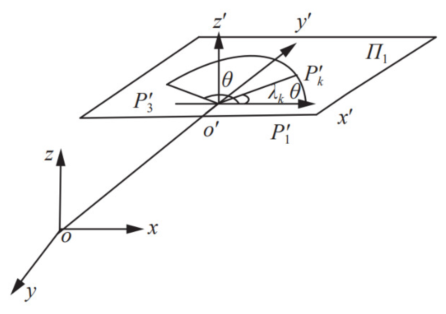
Step 2: Set up the relative coordinate system for the plane of the space arc within the absolute coordinate system . The origin of this relative coordinate system is the center of the arc. Let the direction of the axis be , as depicted in Figure 1. According to coordinates and , the direction cosine of the axis in the relative coordinate system can be expressed as follows:
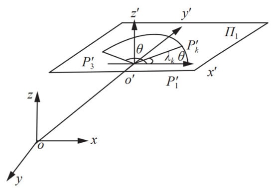
Figure 1.
Circular interpolation based on relative coordinate system.
Consequently, the direction of the relative coordinate system axis is , and its direction cosine is expressed as follows:
where .
According to directions and , the direction of axis can be defined as . Let , then the homogeneous transformation matrix T from the relative coordinate system to the absolute coordinate system can be obtained according to the homogeneous transformation principle represented in Equation (5):
Let the homogeneous coordinate of any point P in the absolute coordinate system be ; then, the coordinate of point P in the relative coordinate system is . As a result, one can write
Step 3: Find the angle between the starting point and the ending point of the arc. Referring to Equation (6), the corresponding coordinates of the three points , , and in space using the relative coordinate system are denoted as , , and .
Moreover, let the position angle at the end of the whole arc trajectory interpolation process be . The following is available:
Step 4: Design the plane in the plane of the relative coordinate system. Based on the homogeneous transformation principle, the following system is obtained:
Then, the interpolation calculation of the circular arc motion can be completed by the S-shaped velocity curve planning for . According to the constraint conditions, such as the arc length and the velocity, they can be divided into several cases, and the linear part can be referred to.
2.3. Velocity Planning
Point-to-point velocity planning can be conceptualized as a method for transitioning from a start point to an end point within a specified time. Currently, widely used velocity planning algorithms in motion planning encompass the ladder-type velocity planning algorithm and the S-type velocity planning algorithm. The trapezoidal curve planning algorithm is characterized by its simplicity, minimal time requirement, swift motor response, and high efficiency. However, it exhibits discontinuous acceleration, leading to a significant flexible impact and relatively lower motion accuracy.
Moreover, the S-shaped curve planning maintains continuous acceleration at any position, thereby avoiding the flexible impact observed in trapezoidal planning. This results in a smoother velocity profile and higher motion accuracy. Nonetheless, the S-shaped algorithm is more complex than trapezoidal programming. Both velocity curve planning approaches are introduced in the following paragraphs.
Trapezoidal curve trajectory planning, also known as linear acceleration and deceleration or T-shaped acceleration and deceleration, stands out as the most widely employed speed control method in manipulator control. Its simple structure and ease of calculation make it a prevalent choice in several motor systems. The acceleration and deceleration process of the trapezoidal velocity curve involves uniform acceleration and uniform deceleration, with the acceleration value maintained as a constant.
In trapezoidal curve planning, the velocity curve can be determined by specifying the starting and ending points of motion, the adding or subtracting of velocity, and the maximum velocity. This process is illustrated in Figure 2.
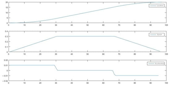
Figure 2.
Trapezoidal speed planning.
The velocity curve of the trapezoidal velocity planning consists of three segments. The first one is a uniform acceleration, the second stage is a uniform velocity, and the third stage is a uniform deceleration. Notably, the rate of increase and decrease in speed during the rise and fall is the same, ensuring that the duration of both the uniform acceleration and deceleration stages is identical. This motion process can be expressed as a piecewise function, and its motion formula is given by
where T represents the total motion time; represents position; represents acceleration; and t represents time. Referring to Figure 2, it becomes evident that the acceleration curve in the trapezoidal velocity planning takes on a step-like form. It is notable that the acceleration is not continuous at the four time points: motion start time, acceleration end time, deceleration start time, and movement end time. This lack of continuity significantly affects the stationarity of the manipulator.
The S-shaped velocity curve is another widely employed velocity planning algorithm in the realm of mechanical control. Diverging from trapezoidal velocity planning, it addresses certain shortcomings associated with the trapezoidal velocity. Moreover, the change rate of acceleration can be controlled by S-type velocity planning. Notably, the acceleration curve in S-type velocity planning is continuous and devoid of sudden acceleration. Consequently, S-type velocity planning emerges as a control strategy that effectively limits vibration.
Furthermore, the S-shaped velocity planning is derived from the S-shaped velocity curve in the process of movement. The velocity curve of the most common S-shaped velocity planning is divided into seven segments as follows:
The first segment: increase the acceleration from zero to the preset value with the constant jerk J.
The second segment: accelerate the operation with a constant acceleration .
The third segment: reduce the acceleration from the preset value to reach zero with a constant negative jerk J.
The fourth segment: achieve with a constant speed a uniform motion.
The fifth segment: reduce the acceleration from zero to the preset value with a constant negative jerk J.
The sixth segment: decelerate with a constant acceleration .
The seventh segment: increase the acceleration from the preset value to zero with a constant jerk J.
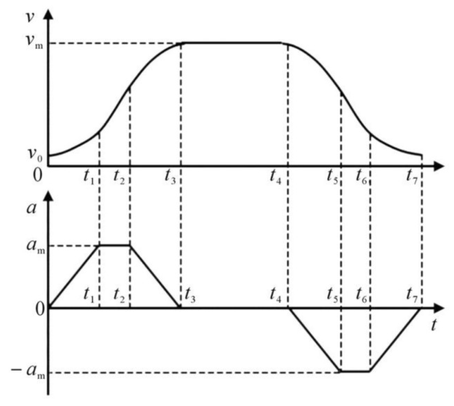
Compared to the three-stage planning of the trapezoidal velocity curve, the S-shaped curve is considerably more complex. By strategically planning acceleration in the acceleration stage, deceleration stage, and acceleration and deceleration stage, S-shaped curve planning achieves superior acceleration continuity compared to trapezoidal curve planning. This substantial improvement significantly impacts during the process of mechanical operation. Therefore, Figure 3 provides a schematic diagram of S-shaped velocity planning.
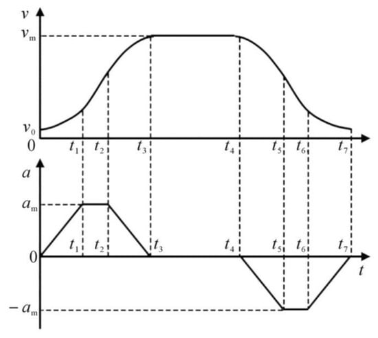
Figure 3.
S-shaped speed planning.
For the S-shaped velocity curve, given the maximum acceleration and the jerk J, the corresponding acceleration of each stage of the seven stages described previously is defined as follows:
Thus, the velocity function corresponding to each stage can be obtained as follows:
According to the time, speed, acceleration, and jerk of each stage, the final position can be expressed as follows:
In the S-shaped curve, the speed determines the speed of the system, whereas the acceleration defines the speed of the system’s acceleration and deceleration. The jerk determines the flexibility of the system; the greater the jerk is, the greater the impact caused by the operation of the manipulator will be. Assuming that the urgency is infinite, the S-shaped velocity curve is switched into a trapezoidal velocity curve.
Furthermore, the S-shaped velocity curve planning consists of planning the parameters relative to the jerk, the acceleration, the velocity, and so on, in each stage to realize a flexible operation in the manipulator. In practical application, the S-shaped velocity curve planning can also be removed from uniform acceleration and deceleration to reduce the number of stages to five. Furthermore, the uniform velocity can also be removed, yielding a total of four stages.
3. Improved Particle Swarm Optimization Algorithm
3.1. Particle Swarm Optimization
PSO, proposed by Eberhart and Kennedy in 1995, serves as a heuristic global search algorithm rooted in swarm intelligence, mimicking the foraging behavior of birds. The essence of the PSO algorithm lies in leveraging all individuals in the population to share information. This facilitates the movement of the entire population in the problem-solving space, transitioning from disorder to order in an evolutionary process, ultimately leading to the acquisition of the optimal solution for the processed problem. The algorithm is known for its simplicity, minimal parameter settings, ease of implementation, and robust global search ability. As a result, it has garnered attention both from researchers and in engineering fields, finding widespread applications.
Furthermore, PSO employs a particle to simulate the bird actions mentioned above. Each particle carries out automatic search in a multidimensional space, and the particle has only two attributes: velocity and position. Therefore, the optimal solution of a single particle is called the individual extreme value whose optimal represents the global optimal solution of this iteration. At the end of each iteration, the particle velocity and position are updated. Finally, the iteration is stopped whenever reaching the maximum number of iterations or the required fitness level; consequently, the optimal solution of the system is obtained. As for the operation process of the algorithm, it is divided into six steps, which are described below.
Step 1: Particle initialization. At this level, a random number is assigned to the position and velocity of each particle. Moreover, the maximum number of iterations, the number of independent variables of the objective function, and the maximum velocity of the particle are set.
Step 2: Whenever a particle updates its position and velocity, its fitness function determines its fitness based on its movement state.
Step 3: The individual optimal solution of each particle is updated. Each particle individual optimal solution is continuously recorded. When the fitness exceeds the individual optimal solution, this latter will be updated.
Step 4: During the learning process of each particle, the global best solution is updated. By comparing the individual best solutions of all particles, the current global best solution is determined and compared with the historical global best solution. If it is better than the historical global best solution, the latter will be updated.
Step 5: All particles’ velocities are updated with the current velocity, individual best, and global best as in Equation (13), and the next position of each particle is updated with the current position and velocity as in Equation (14).
In the equation, represents the inertia weight; and represent the cognitive and social learning factors of the particle, respectively; and are random numbers between 0 and 1; pb and gb denote the individual best solution and global best solution of the particle, respectively; and and represent the velocity and position of the particle, respectively.
Step 6: Termination conditions are established. Different termination conditions are set for diverse problems. The set number of iterations is reached, and the difference between the computation meets the minimum bound.
3.2. Algorithm to Improve
The PSO algorithm has achieved good results in many different scenarios and practical applications. However, the problem of easily falling into local optima has not been well improved. To address this issue, we introduce a local disturbance term and attempt to use adaptive weights to improve the algorithm. The random disturbance term allows particles to jump out of the current region when they fall into the optimum in the early stage, avoiding the situation of falling into local optima. The adaptive weight coefficient adaptively adjusts the weights by calculating the current particle state. The RTPPSO algorithm modifies the PSO algorithm as follows.
To prevent particles from getting trapped in local optimal solutions, a random perturbation term is introduced. This technique aids particles in steering clear of local optima and effectively delving into potential global optima. Specifically, the updated particle position is subject to a random perturbation term, which is a vector crafted in alignment with a designated random distribution. This random perturbation term could follow a normal distribution, a uniform distribution, or another pertinent distribution. Consequently, each particle incorporates an element of randomness, thereby enhancing the diversity of the search. Thus, the particle velocity update formula is as follows:
where is the random disturbance coefficient, which controls the intensity of introduced randomness, and is a random number between −1 and 1.
Referring to Equation (16), it generates the updating principle of the inertia weight. In the equation, and represent the minimum and maximum values of the custom weights, respectively. represents the fitness value of the current particle, while and denote the minimum fitness value and average fitness value of the current particle swarm, respectively. The fitness value is calculated by the subsequent objective function value. These values are normalized; thus, they vary between 0 and 1.
Moreover, Equation (15) can be updated and results in Equation (17):
Here, we also introduce adaptive weight changes for the parameters and in the particle velocity calculation formula, as shown in Equation (18). In this equation, and represent newly designed adaptive parameters; and are constants ranging from 0 to 1.
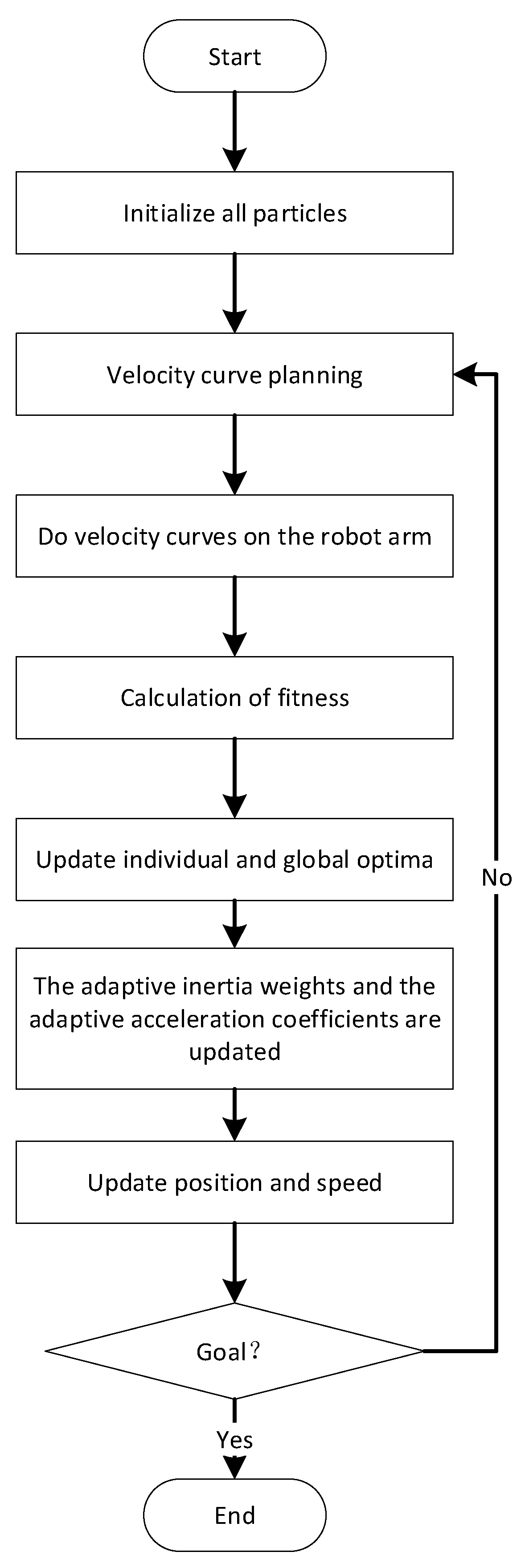
The RTPPSO algorithm has undergone significant changes compared to the traditional PSO algorithm in the formula for updating particle velocities, and its flow chart is shown in Figure 4. All parameters have shifted from their original fixed weights to adaptive weights that can adjust with the changing adaptability of particles. After a series of transformations, the formula for particle velocities now appears as shown in Equation (19).
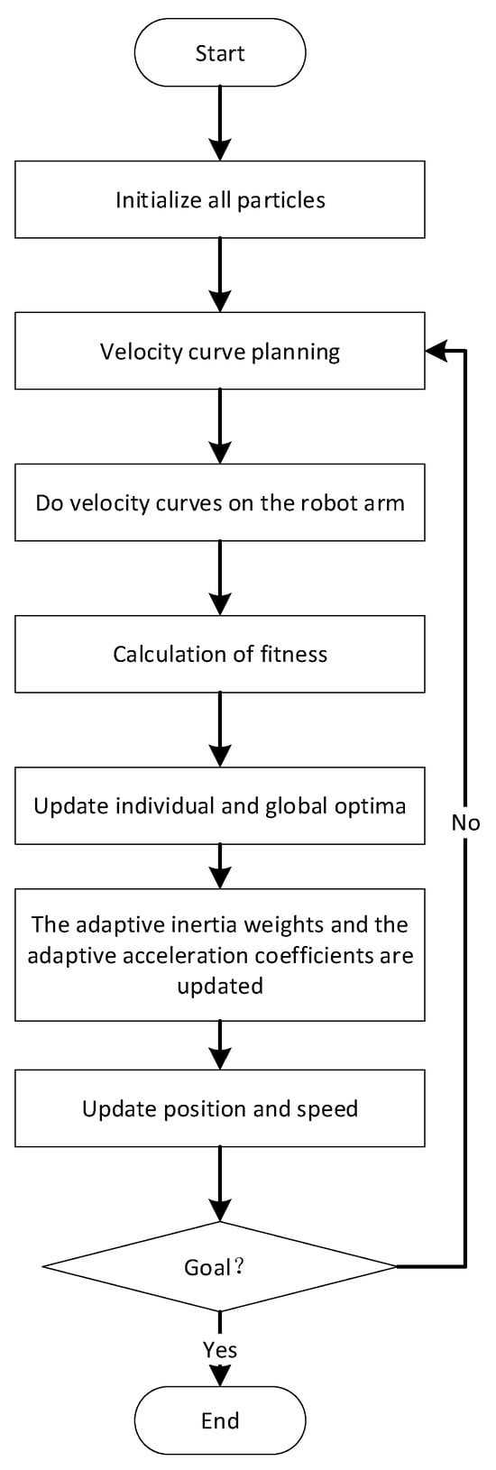
Figure 4.
RTPPSO algorithm flow chart.
3.3. Model Implementation
During the actual operation process, the robotic arm transitions from a stationary state to movement and then to a final stop, requiring acceleration, constant speed, and deceleration stages to ensure smooth operation and reduce vibrations. To achieve this, the velocity profile is composed of acceleration end points , constant speed end points , and maximum angular velocities , but where and are both known. Each axis motor has a different velocity profile based on the specific circumstances.
The angular velocity in the first stage is represented in Equation (20), while in the third stage is depicted in Equation (21).
The velocity curve can be categorized into three stages, and the angular velocity of each stage is expressed in Equation (22).
If the velocity curve is known, the angular displacement can be calculated by integrating. The specific calculation process is shown in Equations (23)–(26). The maximum angular velocity can also be calculated from these.
The objective function is a very important index in the trajectory rule, and the optimal trajectory can be obtained only by designing the objective function reasonably. This paper is mainly to reduce the jitter during the operation of the robot arm so that it can run smoothly and ensure the grabbing quality of the robot arm. Therefore, in the design of our objective function, we comprehensively consider the angular acceleration of the X axis, Y axis, Z axis, and rotation axis. The objective formula is as follows:
where , , , and represent the maximum acceleration of the X axis, Y axis, Z axis, and rotation axis, respectively.
In the first step, the setup is initialized, and then the acceleration end time and uniform end time for each motor are updated.
In the second step, the step is to use the interpolation algorithm to fit the velocity curve. Then, Equations (20)–(26) are used to calculate the angular displacement, angular velocity. and maximum angular velocity of the motor.
In the third step, the step is to run the robot arm according to the designed speed curve.
In the fourth step, the fitness value is calculated using sensor information based on four reference indices, including the maximum acceleration of the X, Y, and Z axes, along with the rotation axis.
In the fifth step, the fitness values are calculated, the individual and global optimal values are updated, and the adaptive weight parameters and adaptive acceleration parameters of the particles are updated. Then, it judges whether the set number of iterations is reached, if not, it returns to step 1; If reached, the iteration ends. The output is the current optimal value.
4. Experimental Simulation
4.1. Experiment
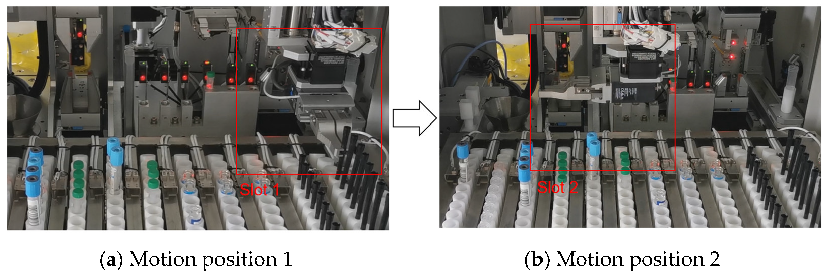
In the practical utilization process, specific requirements exist for the speed and synchronization of the sample manipulator. In order to better realize the trajectory planning operation of the robot arm, the parameters used are designed as follows according to the following marks. The number of iterations is set to 9, the total number of particles is set to 7, and parameter is set to 0, is set to 1, is set to 2.05, and is set to 0.5 in the particle swarm optimization algorithm. To meet these requirements, in the simulation experiments, each action of the robotic arm must be completed within 3 s, as indicated by the red box annotations in Figure 5a,b.
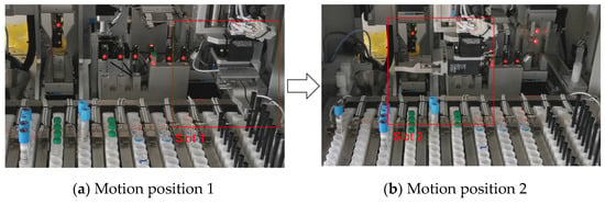
Figure 5.
Machine arm motion illustration.
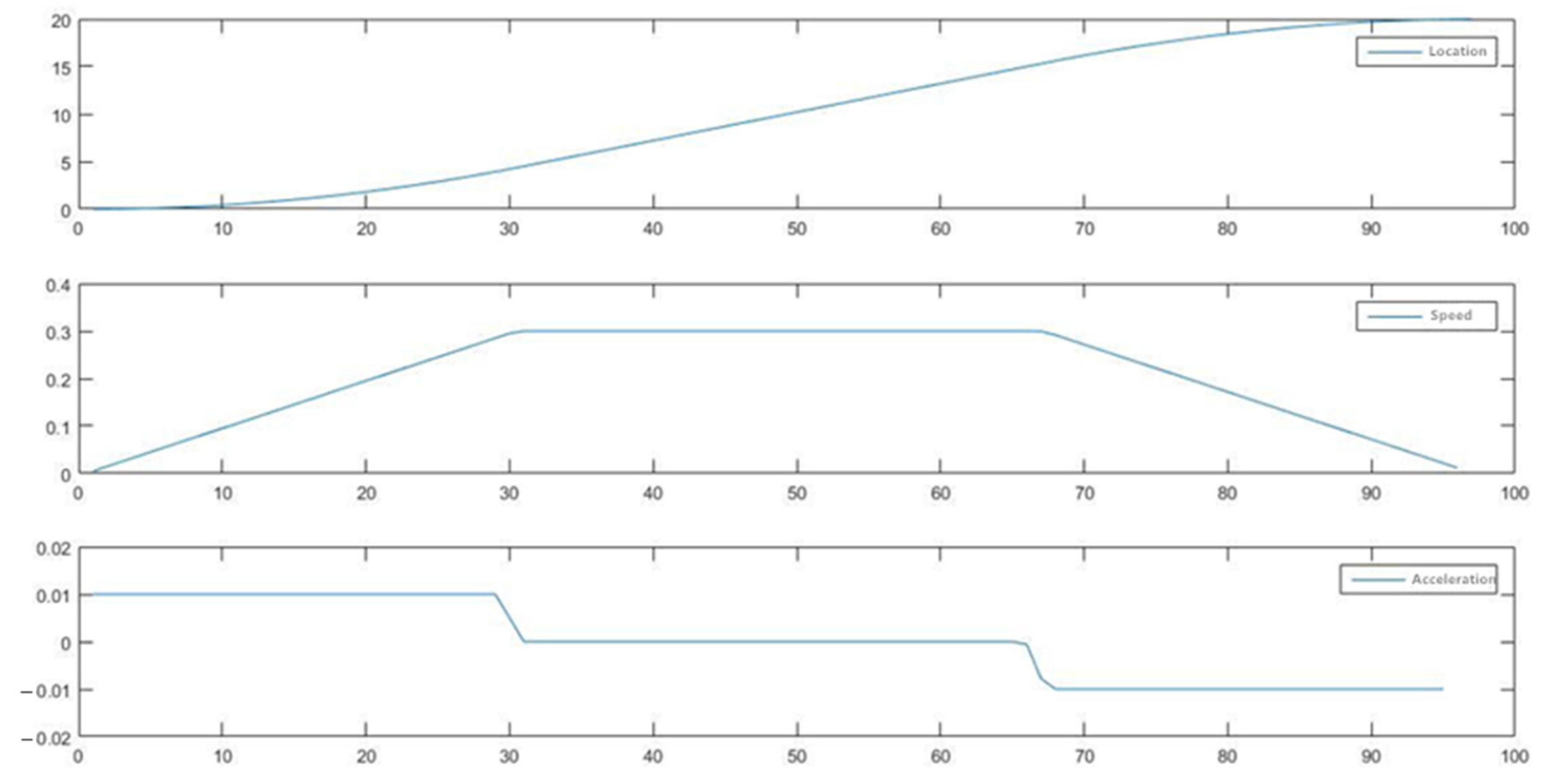
First of all, a simulation is conducted comparing the trapezoidal velocity curve to the S-shaped velocity curve. The S-shaped curve is designed in five sections. For a comprehensive analysis, the same maximum speed and movement time are used to ensure a clear comparison.
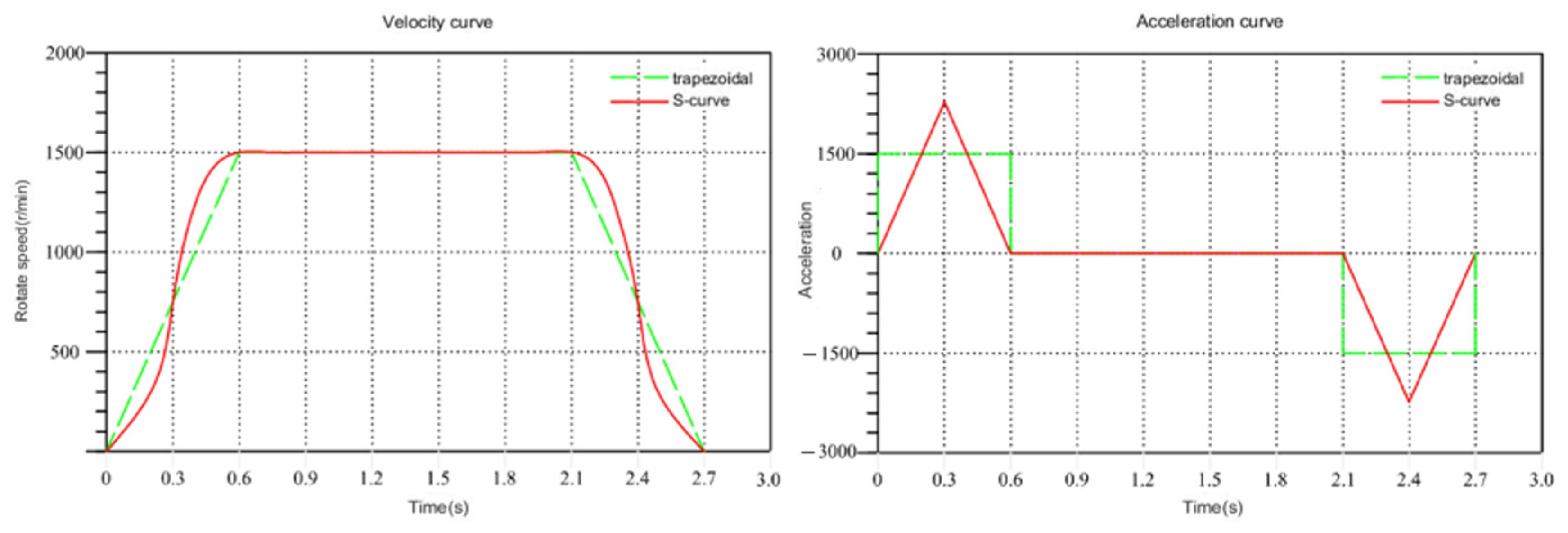
The velocity and acceleration curves of both are shown in Figure 6. It is evident from the figure that despite having the same maximum speed and displacement, the trapezoidal curve exhibits obvious acceleration discontinuity. This discontinuity is likely to cause a certain degree of jitter during the movement of the mechanical arm. Moreover, the S-shaped curve, owing to its continuous change in acceleration, avoids the impact of sudden acceleration during operation. However, the acceleration curve reveals that the maximum acceleration of the S-shaped curve surpasses that of the trapezoidal curve. When the maximum acceleration is excessively high and the acceleration time is short, the mechanical arm may experience jitter due to rapid acceleration changes. Consequently, adjustments are required for maximum acceleration in the S-shaped curve.
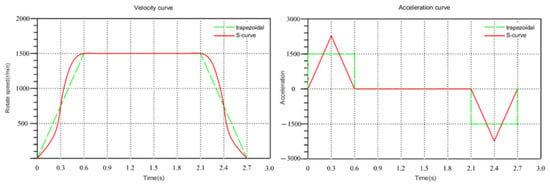
Figure 6.
Comparison of trapezoidal curve and S-curve.
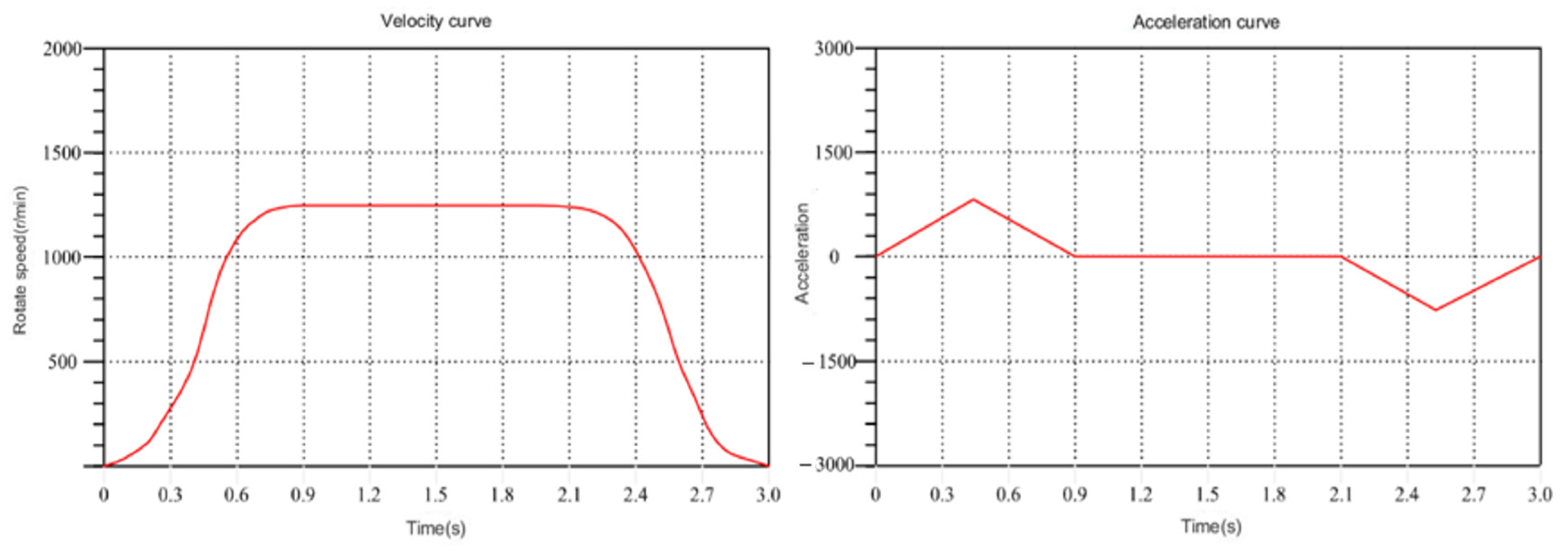
The manipulator’s displacement is determined based on the starting point and the ending point. Velocity curve planning is then executed for this path, employing an improved particle swarm optimization algorithm for learning. Figure 7 illustrates the optimal particle velocity curve of the X axis after the first iteration. In the figure, the X axis represents time, and the Y axis represents motor speed. Observing the figure, it becomes apparent that the maximum velocity and acceleration of the first iteration are relatively large, with a relatively short running time. The acceleration time is small, and the acceleration is significant, indicating that the mechanical arm is greatly influenced by inertia during movement.

Figure 7.
Velocity curve of the first iteration.
This influence is not conducive to the stable operation of the mechanical arm.
After multiple learning iterations, the global optimal solution is obtained. The iterative results enable the deviation of the velocity curve and acceleration curve, as shown in Figure 8. Compared to the results of the first iteration, the speed curve, optimized by the PSO algorithm, is smoother than that of the first iteration in the specified running time. Moreover, the maximum acceleration is greatly reduced, and the acceleration and deceleration time are also significantly improved. This is conducive to the stable operation of the manipulator.
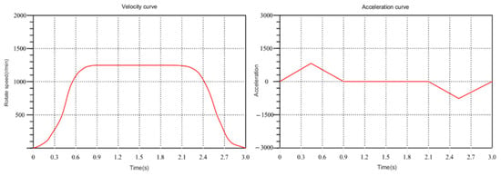
Figure 8.
Velocity curve of global optimal solution.
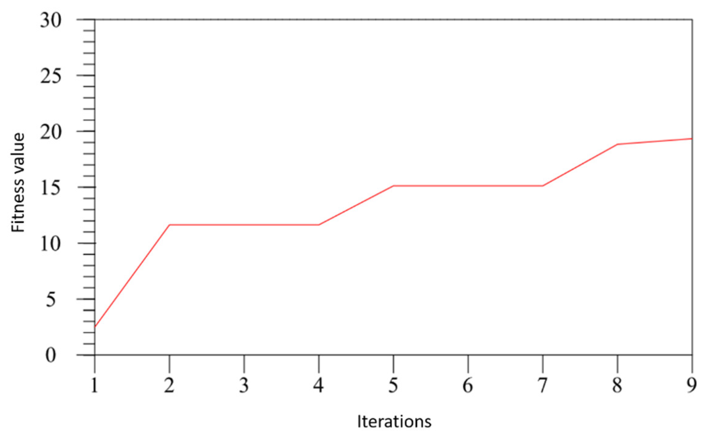
According to the fitness function, the fitness value at the end of each iteration is computed, and the fitness learning curve is obtained as illustrated in Figure 9. According to the learning curve, using the improved PSO algorithm to plan the velocity curve, the optimal solution of the system is generated after a few iterations. This effectively improves the slow convergence of the traditional PSO algorithm and effectively avoids the influence of the local optimal solution on the result by altering the learning factor.
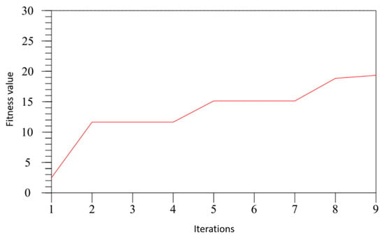
Figure 9.
Fitness learning curve.
In this study, an improved PSO algorithm was proposed to plan the velocity curve of the motion of the industrial robot arm. After several learning periods, the stability of the operation of the robot arm was significantly improved, and the four-axis acceleration was in a relatively stable state. The results proved the feasibility and efficiency of the trajectory planning algorithm deployed in this paper.
4.2. Discussion
To validate the effectiveness of the proposed algorithm, we compared the acceleration and operational speed of the robotic arm using the proposed algorithm against other optimization algorithms. We recorded the differences before and after applying the algorithm. In the comparative experiment, we designed a set of rotations and grasping actions for the robotic arm to compare the time taken and acceleration variations.
According to Table 1, the RTPPSO algorithm demonstrates the best optimization effect on the robotic joint impacts. The average impacts on the drive arm joints before and after optimization are 2.23 × 10⁶ deg/s3 and 4.58 × 10⁵ deg/s3, respectively, resulting in a reduction in impacts by 79.45%. It can be seen from Table 2 that our algorithm also improves the grasping speed to some extent, which can effectively improve the grasping efficiency of the robotic arm. Compared to other algorithms, the RTPPSO algorithm has better realized trajectory planning work, enhancing the operational efficiency of the robotic arm while effectively reducing vibration issues during operation. Compared to other algorithms, the RTPPSO algorithm better addresses vibration issues during operation. However, this study did not incorporate optimization of computational efficiency, which relates to the operational time of the robotic arm, into the design of the optimization problem. Further improvements are needed in future iterations to address this aspect.

Table 1.
Impact optimization comparison.

Table 2.
Time optimization simulation comparison.
5. Conclusions
This paper investigates the motion stability of industrial robotic arms. To address the challenge of optimizing system speed adjustments to reach the optimal positions, an improved Robot Trajectory Planning Particle Swarm Optimization (RTPPSO) algorithm is proposed. By incorporating a random perturbation term and designing adaptive weights, we effectively mitigated the issue of the PSO algorithm getting stuck in local optima. To validate the algorithm’s effectiveness, we conducted simulation experiments. The final experimental curves demonstrate the favorable effects of our algorithm on speed planning, showing smooth operation with gentle acceleration and deceleration processes, without abrupt changes. Subsequent comparative experiments further confirmed that our algorithm can effectively ensure the smooth operation of the robotic arm.
In the future, we plan to validate this algorithm in realistic scenarios that involve obstacles or angular constraints. This will ensure that the algorithm proposed in this paper is applicable to a broader range of industrial settings.
Author Contributions
N.W.: conceptualization, methodology, software, writing—original draft preparation, manuscript writing, visualization, investigation, writing—reviewing and editing. D.J.: supervision. Z.L.: data curation, investigation. Z.H.: software, validation. All authors have read and agreed to the published version of the manuscript.
Funding
We acknowledge that this work was supported by the Fundamental Research Funds for the Central Universities (grant 2022YJS020).
Institutional Review Board Statement
Not applicable.
Informed Consent Statement
Not applicable.
Data Availability Statement
The original contributions presented in the study are included in the article, further inquiries can be directed to the corresponding author.
Conflicts of Interest
The authors declare no conflicts of interest.
References
- Zhao, J.; Zhu, X.; Song, T. Serial Manipulator Time-Jerk Optimal Trajectory Planning Based on Hybrid IWOA-PSO Algorithm. IEEE Access 2022, 10, 6592–6604. [Google Scholar] [CrossRef]
- Batista, J.; Souza, D.; Silva, J.; Ramos, K.; Costa, J.; dos Reis, L.; Braga, A. Trajectory Planning Using Artificial Potential Fields with Metaheuristics. IEEE Lat. Am. Trans. 2020, 18, 914–922. [Google Scholar] [CrossRef]
- Rubio, F.; Valero, F.; Sunyer, J.L.; Garrido, A. The simultaneous algorithm and the best interpolation function for trajectory planning. Ind. Robot. Int. J. Robot. Res. Appl. 2010, 37, 441–451. [Google Scholar] [CrossRef]
- Sun, J.; Han, X.; Zuo, Y.; Tian, S.; Song, J.; Li, S. Trajectory Planning in Joint Space for a Pointing Mechanism Based on a Novel Hybrid Interpolation Algorithm and NSGA-II Algorithm. IEEE Access 2020, 8, 228628–228638. [Google Scholar] [CrossRef]
- Chen, W.-C.; Chen, C.-S.; Lee, F.-C.; Chen, L.Y. High speed blending motion trajectory planning using a predefined absolute accuracy. Int. J. Adv. Manuf. Technol. 2019, 104, 2179–2193. [Google Scholar] [CrossRef]
- Shi, C.; Ye, P. The look-ahead function-based interpolation algorithm for continuous micro-line trajectories. Int. J. Adv. Manuf. Technol. 2011, 54, 649–668. [Google Scholar] [CrossRef]
- Luo, L.-P.; Yuan, C.; Yan, R.-J.; Yuan, Q.; Wu, J.; Shin, K.-S.; Han, C.-S. Trajectory planning for energy minimization of industry robotic manipulators using the Lagrange interpolation method. Int. J. Precis. Eng. Manuf. 2015, 16, 911–917. [Google Scholar] [CrossRef]
- Nadir, B.; Mohammed, O.; Minh-Tuan, N.; Abderrezak, S. Optimal trajectory generation method to find a smooth robot joint trajectory based on multiquadric radial basis functions. Int. J. Adv. Manuf. Technol. 2022, 120, 297–312. [Google Scholar] [CrossRef]
- Abu-Dakka, F.J.; Assad, I.F.; Alkhdour, R.M.; Abderahim, M. Statistical evaluation of an evolutionary algorithm for minimum time trajectory planning problem for industrial robots. Int. J. Adv. Manuf. Technol. 2017, 89, 389–406. [Google Scholar] [CrossRef]
- Liu, Y.; Guo, C.; Weng, Y. Online Time-Optimal Trajectory Planning for Robotic Manipulators Using Adaptive Elite Genetic Algorithm with Singularity Avoidance. IEEE Access 2019, 7, 146301–146308. [Google Scholar] [CrossRef]
- Wang, M.; Luo, J.; Zheng, L.; Yuan, J.; Walter, U. Generate optimal grasping trajectories to the end-effector using an improved genetic algorithm. Adv. Space Res. 2020, 66, 1803–1817. [Google Scholar] [CrossRef]
- Chen, D.; Li, S.; Wang, J.; Feng, Y.; Liu, Y. A multi-objective trajectory planning method based on the improved immune clonal selection algorithm. Robot. Comput. Manuf. 2019, 59, 431–442. [Google Scholar] [CrossRef]
- Jin, M.; Wu, D. Collision-Free and Energy-Saving Trajectory Planning for Large-Scale Redundant Manipulator Using Improved PSO. Math. Probl. Eng. 2013, 2013, 208628. [Google Scholar] [CrossRef]
- Cao, B.; Sun, K.; Li, T.; Gu, Y.; Jin, M.; Liu, H. Trajectory Modified in Joint Space for Vibration Suppression of Manipulator. IEEE Access 2018, 6, 57969–57980. [Google Scholar] [CrossRef]
- Liu, C.; Cao, G.-H.; Qu, Y.-Y.; Cheng, Y.-M. An improved PSO algorithm for time-optimal trajectory planning of Delta robot in intelligent packaging. Int. J. Adv. Manuf. Technol. 2020, 107, 1091–1099. [Google Scholar] [CrossRef]
- Lv, X.; Yu, Z.; Liu, M.; Zhang, G.; Zhang, L. Direct Trajectory Planning Method Based on IEPSO and Fuzzy Rewards and Punishment Theory for Multi-Degree-of Freedom Manipulators. IEEE Access 2019, 7, 20452–20461. [Google Scholar] [CrossRef]
- Li, Y.; Ge, S.S.; Wei, Q.; Gan, T.; Tao, X. An Online Trajectory Planning Method of a Flexible-Link Manipulator Aiming at Vibration Suppression. IEEE Access 2020, 8, 130616–130632. [Google Scholar] [CrossRef]
- DU, Y.; Chen, Y. Time Optimal Trajectory Planning Algorithm for Robotic Manipulator Based on Locally Chaotic Particle Swarm Optimization. Chin. J. Electron. 2022, 31, 906–914. [Google Scholar] [CrossRef]
- Yang, Y.; Xu, H.-Z.; Li, S.-H.; Zhang, L.-L.; Yao, X.-M. Time-optimal trajectory optimization of serial robotic manipulator with kinematic and dynamic limits based on improved particle swarm optimization. Int. J. Adv. Manuf. Technol. 2022, 120, 1253–1264. [Google Scholar] [CrossRef]
- Wang, L.; Wu, Q.; Lin, F.; Li, S.; Chen, D. A New Trajectory-Planning Beetle Swarm Optimization Algorithm for Trajectory Planning of Robot Manipulators. IEEE Access 2019, 7, 154331–154345. [Google Scholar] [CrossRef]
- Zhang, W.; Fu, S. Time-optimal Trajectory Planning of Dulcimer Music Robot Based on PSO Algorithm. In Proceedings of the 32nd Chinese Control and Decision Conference (CCDC), Hefei, China, 22–24 August 2020; pp. 4769–4774. [Google Scholar]
Disclaimer/Publisher’s Note: The statements, opinions and data contained in all publications are solely those of the individual author(s) and contributor(s) and not of MDPI and/or the editor(s). MDPI and/or the editor(s) disclaim responsibility for any injury to people or property resulting from any ideas, methods, instructions or products referred to in the content. |
© 2024 by the authors. Licensee MDPI, Basel, Switzerland. This article is an open access article distributed under the terms and conditions of the Creative Commons Attribution (CC BY) license (https://creativecommons.org/licenses/by/4.0/).

