Featured Application
The strengthening of the columns and the connections of the columns with the beams for reinforced concrete buildings designed and constructed according to older codes is crucial for regions prone to seismic activity. Herein, the application of the innovative C-FRP ropes for the strengthening of these structural elements is featured. The experimental results yielded from testing real-scale columns demonstrated that this strengthening technique is both highly effective and easy to implement. Moreover, it is emphasized that the C-FRP ropes technique can easily be applied by the practicing engineer in structures with complex configuration without any geometrical restraints.
Abstract
The application of the innovative C-FRP ropes for the strengthening of reinforced concrete columns is experimentally examined. Two real-scale specimens with the same geometrical characteristics and the same steel reinforcements were constructed for the needs of this investigation. The primary objective of the study is to investigate the efficacy of the use of C-FRP ropes as externally mounted reinforcement for the strengthening of deficient external columns. In this direction, (a) C-FRP ropes are applied as longitudinal reinforcement of the column for the increase in the flexural strength, (b) C-FRP ropes are applied as external confining stirrups in the critical end parts of the column for the improvement of the concrete strength and the development of local element ductility, and finally (c) C-FRP ropes are applied as external stirrups in the form of diagonal X-shaped reinforcement for the increase in the capacity of the part of the column connected with the beam (joint panel). Both specimens are tested under the same cyclic loading procedure that comprises seven steps and each step includes three full loading cycles. The maximum loads of the strengthened specimen at the three loading cycles of the seventh step were 40%, 72% and 87% higher than the corresponding ones of the unstrengthened specimen. On the other hand, the measured shear deformations of the joint panel of the pilot (unstrengthened) specimen at the sixth and the seventh steps were 43% and 44% higher than the corresponding ones of the strengthened specimen. In general, it is concluded that the strengthened column exhibited improved hysteretic response and the whole behavior was apparently improved compared to the pilot specimen without strengthening in terms of maximum loads per loading step, dissipated energy, and shear deformations of the joint panel. In particular, it is stressed that the measured shear deformations of the joint panel and strain gauge measurements have substantiated that the column and the connection panel of the strengthened specimen remain almost intact, whereas damage and eventually failure have been located in the column and the joint panel of the pilot specimen. Additionally, it is emphasized that the C-FRP ropes can easily be applied in structures with complex configuration without any geometrical restraints.
1. Introduction
During seismic excitations, structural damages are most frequently observed at the end parts of the columns and at the connections of the columns with the beams. The extent and the severity of the damages are often significant for reinforced concrete (RC) structures built to older regulations. This is due to inadequate older provisions that very often resulted in the construction of buildings with insufficient reinforcement in the critical end parts of the columns. Furthermore, the total lack of stirrups within the connection panel of the columns with the beams is also a very common characteristic of most of the older buildings. Thereupon, it is evident that in earthquake prone areas the scientific investigation of methods for the strengthening of deficient columns and their connections to beams is of utmost importance.
One well-known, effective and widely used method for the strengthening of structural elements is the application of high strength reinforced concrete jacketing [1,2,3]. The application of thin jackets using high strength cement mortar and dense small diameter reinforcements has also been experimentally investigated and reported in the literature [4]. Nevertheless, jacketing techniques require extensive labor, reinforcement detailing, and a long disruption period in the usability of the building.
In recent decades, the application of Fiber Reinforced Polymer (FRP) sheets has been studied and proposed as an alternative method for the strengthening of RC beam–column joints [5,6]. FRP sheets in different configurations have been externally bonded onto full scale RC joints to provide reinforcing fibers in critical directions and ensure increased shear strength [7,8,9,10,11,12]. It is important that the usage of FRP sheets instead of jacketing reduces the application demands in terms of reinforcement detailing, construction labor and disruption periods. In general, based on the obtained results, FRP strengthening succeeded in improving the structural behavior of the joints [13,14,15,16]. However, applying U-form jacketing to beams [17] inherent restrictions due to the existence of slabs usually exist and in case of strengthening of beam–column connections [5,6] geometrical obstacles from the transversal beams also appear. These application problems often limit the effectiveness of the FRP sheets and in some cases render the method not even feasible to apply.
A new and easily applied strengthening technique based on Near Surface Mounted (NSM) reinforcements has also been repeatedly presented in recent literature. The NSM techniques usually use FRP bars or new steel products. These techniques have been reported for the strengthening of reinforced concrete slabs [18]; externally applied steel meshes [19] and external bars [20] have also been reported. Moreover, carbon FRP bars as an alternative to steel reinforcements are studied and reported, too [21,22].
Recently, flexible ropes of Carbon Fiber-Reinforced Polymers (C-FRP) applied as external reinforcement for the strengthening of the body of beam–column joints have been experimentally investigated and reported in the literature [23,24]. Flexible composite rope strengthening has offered some unique application advantages as it allows for external wrapping of columns even without the use of impregnation or bonding agents. It is self- anchored and presents non-fracture and strain redistribution characteristics prolonging the axial strain ductility of the RC column and protecting it against collapse [25,26]. Carbon FRP ropes with resin impregnation were successfully applied as near-surface mounted (NSM) or as embedded through section (ETS) in joints [27]. Resin-impregnated FRP ropes have been used as flexural or shear strengthening reinforcement in beams [28]. Further, comparison of this technique with the use of FRP sheets for the strengthening of the beam–column joints has also been reported [29].
It is stressed that the interface strength between C-FRP bars and concrete is a critical issue, particularly due to the differences in material properties between organic (C-FRP) and inorganic (concrete) materials. The organic resins employed as binders have disadvantages such as poor response at high temperatures, difficulty in application on moist areas or low temperatures, and non-compatibility with substrates [30,31,32,33,34,35,36,37]. In any case, a high strength and superiority in comparison to other materials in ambient temperature along with easy-to-apply features make the application of FRP materials very attractive.
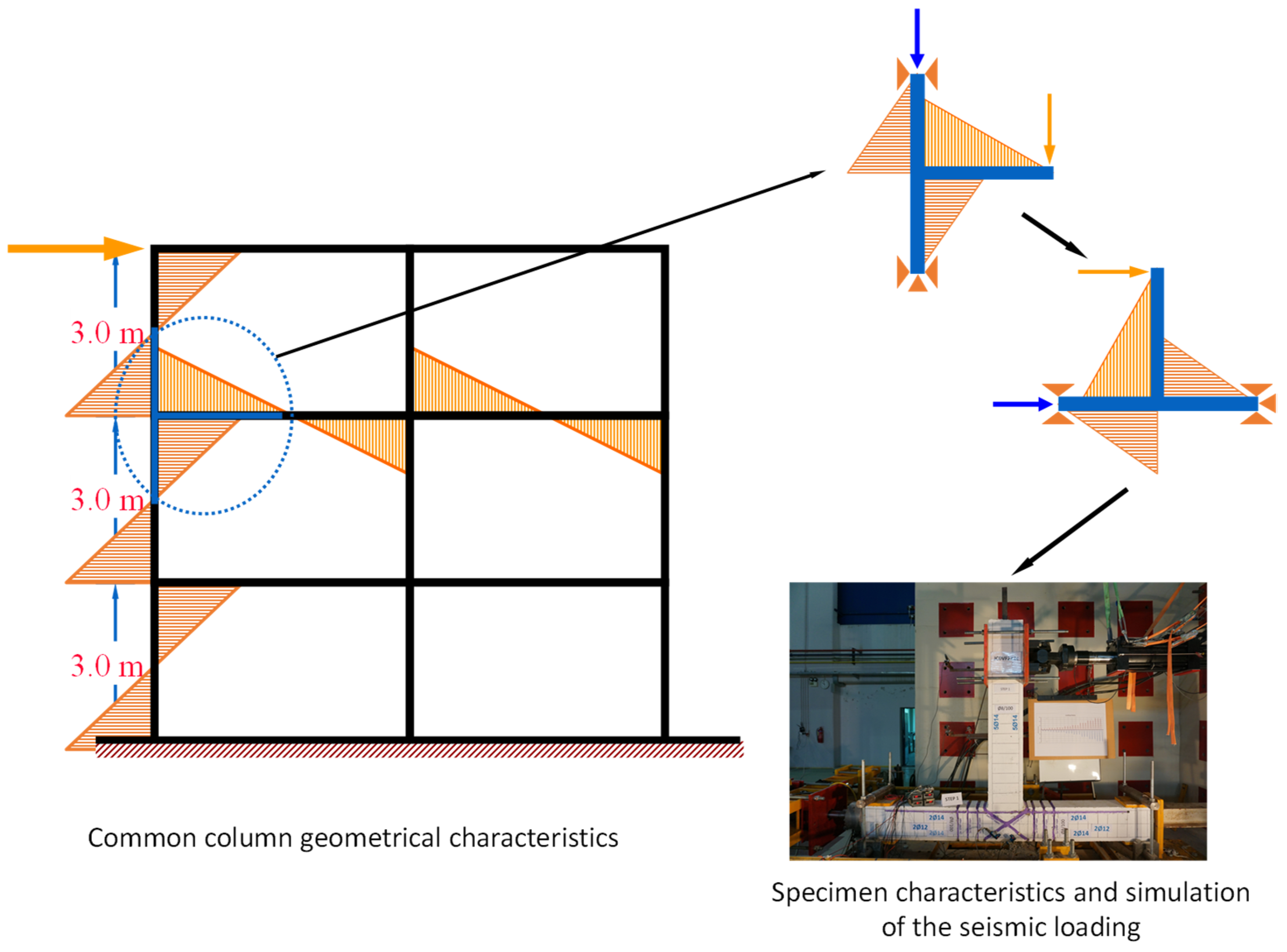
In this study, the innovative use of C-FRP ropes as external reinforcement for the strengthening of deficient columns is experimentally examined. Two real-scale specimens with the same geometrical characteristics and the same steel reinforcements were constructed for the needs of this investigation (Figure 1). One of the specimens (JC0VF2X2c) was strengthened with C-FRP ropes.
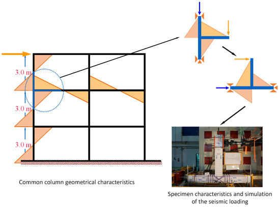
Figure 1.
Column characteristics of common RC frame structures and simulation of the seismic loading in the tested specimens.
Specifically, C-FRP ropes were applied (a) as external longitudinal reinforcement of the column to increase its flexural strength; (b) C-FRP ropes were also used as external stirrups for the confinement of the critical parts of the column in order to improve the concrete strength and the local ductility of the column, and (c) C-FRP ropes were also applied diagonally on the two sides of the joint body of the specimen, providing this method an X-form external shear reinforcement for the improvement of the seismic behavior of the connection of the column with the beam.
From the experimental results, it is observed that the externally applied C-FRP ropes effectively improved the cyclic response of the strengthened column in comparison with the behavior of the same specimen without the strengthening. It is easily concluded from the study of the maximum loads per loading step, dissipated energy, and the shear deformations of the joint panel. In particular, from the measured shear deformations of the joint panel and the strain gauge measurements, it is substantiated that the column and the connection panel of the strengthened specimen remained almost intact, whereas in the unstrengthened pilot specimen damage and eventually failure have been located in the column and the joint panel.
2. Geometrical and Mechanical Characteristics of the Specimens—Materials
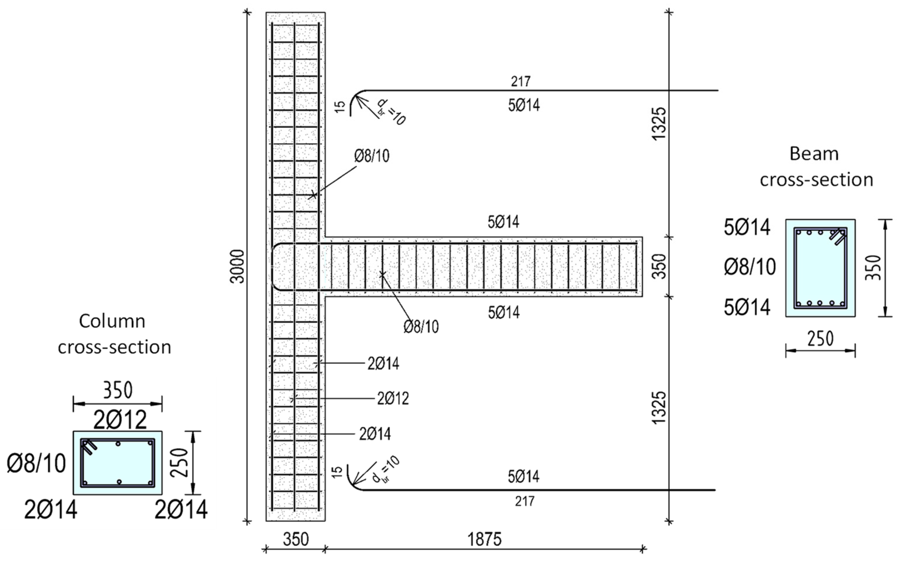
Geometrical characteristics and seismic loading of the real columns of common RC frame structures are presented in Figure 1. The geometry and the design of the specimens used in this study are based on these characteristics and were adopted to be representative of the columns and beam–column connections of real structures. The length of the column was 3.0 m with a 35/25 cm cross-section whereas the cross-section of the beam was 25/35 cm. The details of the geometry are presented in Figure 2.
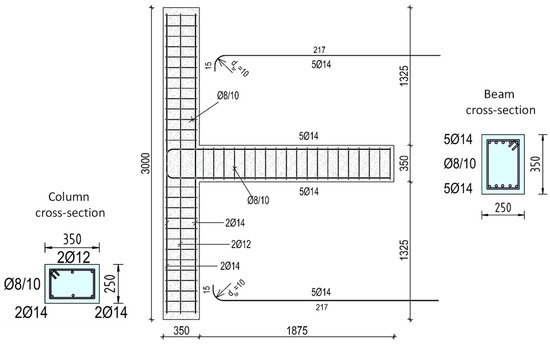
Figure 2.
Real-scale specimens. Configuration of the reinforcements of the tested specimens.
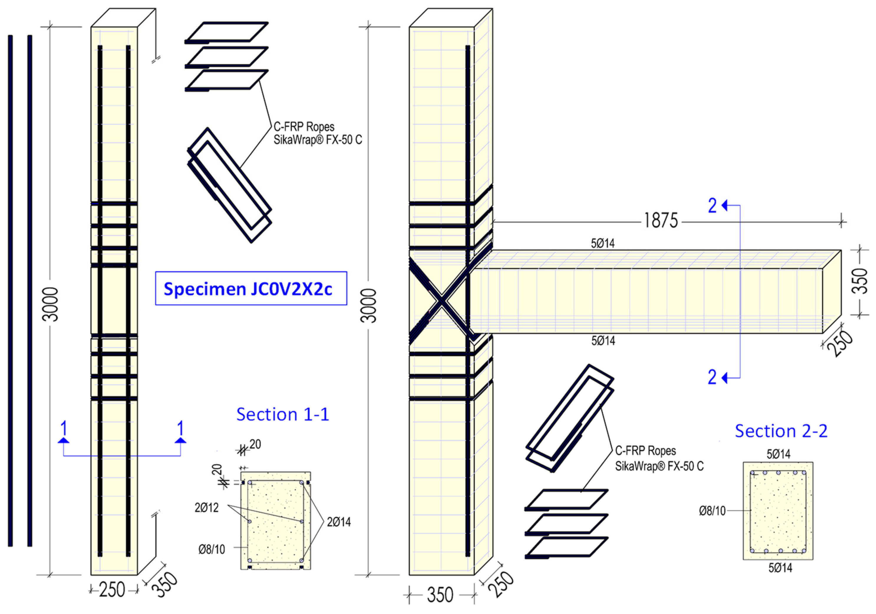
The first column specimen (JC0V) is used as a pilot specimen, whereas the column part of the second one was strengthened with the application of C-FRP ropes. Ropes are used as external longitudinal reinforcements for the strengthening of the column against flexure (Figure 3). Further, C-FRP ropes are applied as external stirrups for the confinement of the critical end parts of the column, too. Finally, ropes are also applied in the form of diagonally placed stirrups for the shear strengthening of the joint body of the specimen (specimen JC0F2X2c).
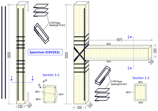
Figure 3.
Specimen JC0V2X2c. Strengthening of the column and the column to beam connection panel using C-FRP ropes. Ropes are used as external longitudinal reinforcements for the strengthening of the column against flexure and for the confinement of the critical end parts of the column as external stirrups. Further, ropes are also applied in the form of diagonally placed stirrups for the shear strengthening of the joint body of the specimen.
The C-FRP rope is flexible and therefore it is easily placed in U-shaped grooves. Properly formed grooves are crucial for the effective application of the strengthening technique since grooves keep the ropes at the correct location and protect them from local injuries. The depth and width of the notches are 25 mm and 30 mm, respectively, whereas the inner part of the grooves has to be clean before the installation of the ropes.
While the grooves decrease the shear strength of the joint, their application is necessary, as the X shape of the rope tends to move when it comes to tension. The notches are necessary so that the rope does not leave its initial position. Therefore, it was decided to provide adequate grooving all around the perimeter of the region under retrofit. An adequate concrete cover has to be provided, as the internal steel reinforcement has to be protected against direct damage or galvanic corrosion from contact with carbon fibers. The grooves are of great importance as they prevent the rope from slipping over the back surface of the column. They are well rounded at the eight corners of the grooves in the columns to maximize the force exerted by the ropes against the two diagonal concrete sections and to avoid the excessive stress concentration that may cause damage. An important point is the application of a two-component epoxy resin in the notches as an adhesive substance between the ropes and the concrete. The composite rope is placed inside the grooves by hand while stretching it against the concrete member. The application of C-FRP ropes in the grooves serves to reinforce the area, helping to counteract any minor imperfections or weaknesses caused by the grooving process. Finally, the grooves are fully infilled with the epoxy resin paste. Filling the notches with high strength-epoxy paste ensures that the rehabilitation of the extracted concrete cover of the notches.
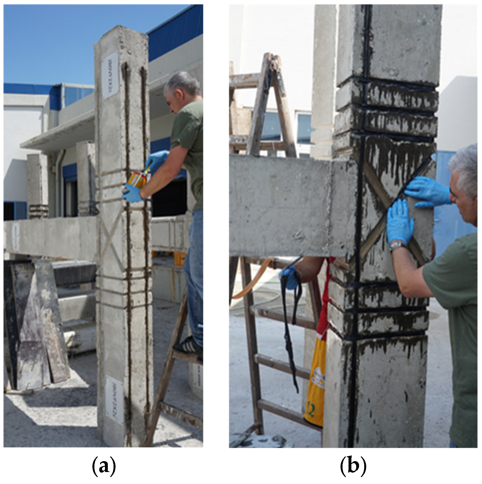
Furthermore, inside the grooves the corners of the column in the notches have to be well rounded by grinding and any protrusions on the surfaces have to be smoothed to ensure optimal adhesion and performance of the C-FRP ropes. The placement of the longitudinal C-FRP ropes in the grooves along the height of the column is presented in Figure 4a, whereas the application of the C-FRP ropes as external shear reinforcement in X-formed grooves at the two sides of the joint panel is presented in Figure 4b.

Figure 4.
Application of the C-FRP ropes on the specimen JC0V2X2c. The ropes are placed deep in U-shaped notches. The incision of the notches takes place at the design positions of the C-FRP ropes. (a) Application of the longitudinal C-FRP ropes as external flexural reinforcement of the column and (b) application of the C-FRP ropes as external stirrups diagonally placed for the shear strengthening of the joint body of the specimen.
Supplementary compression tests of concrete were conducted for the evaluation of the concrete strength. The mean value of the compressive concrete strength was almost 34 MPa, whereas the tensile strength of the steel reinforcement was 550 MPa. The modulus of elasticity and tensile strength of the used C-FRP fibers of the applied ropes, as specified by the manufacturer, were 240 GPa and 4 GPa, respectively.
Carbon Fiber-Reinforced Polymers (C-FRPs) ropes and sheets tend to have a higher initial material cost per unit compared to traditional construction materials like concrete and reinforcing steel bars. However, the installation procedure for C-FRP ropes is faster and less labor-intensive than traditional methods; it is stressed that they are lightweight and easy to handle and to apply, while fewer workers and lighter equipment are required, leading to lower labor costs. A major advantage of the C-FRP ropes is the substantial reduction in construction time and the speed and ease of their application, especially in difficult or confined areas, minimize downtime and disruption, which can translate to significant cost savings in projects where time is critical. Further, C-FRP materials are durable and more resistant to corrosion, reducing long-term maintenance costs.
On the other hand, it is widely accepted that concrete is relatively inexpensive as a material, making concrete jacketing a lower-cost option in terms of raw materials. However, significant quantities of concrete and additional reinforcing bars are required to provide sufficient structural strengthening. The installation process for concrete jacketing is labor-intensive, time-consuming, and concrete jacketing often involves significant disruption to the existing structure. Thus, the character of this structural intervention can increase project downtime, especially in occupied buildings. Further, concrete is susceptible to cracking, spalling, and corrosion of embedded steel, especially in aggressive environments, and over time, the maintenance costs for concrete jackets can be substantial.
Steel is moderately priced and more expensive than concrete; it requires specialized labor, heavy lifting equipment, and precise installation techniques. The labor-intensive nature of the work can drive up costs significantly. Installing steel jackets usually involves welding and bolting, which can be time-consuming and disruptive to the existing structure. Steel is highly susceptible to corrosion, especially in moist or salty environments, and, obviously, the necessary maintenance to prevent rust increases the long-term costs.
In general, although the upfront costs of C-FRP ropes are higher, the overall life cycle cost including installation, long-term maintenance and durability may be proved to be lower than traditional methods, especially for projects requiring fast execution and high-performance standards.
While the study focuses primarily on short term effectiveness during seismic excitations, the importance of aging, durability, and environmental impact are also stressed. Previous research has demonstrated that the C-FRP materials exhibit excellent long-term durability due to their resistance to corrosion and chemical attacks. A study on the long-term durability of C-FRPs presented results that these materials effectively maintain their mechanical properties over time [38]. Further investigation on the aging of C-FRP materials indicated only minimal degradation in mechanical properties after extended periods [39]. Finally, it is noted that C-FRP materials are known for their high resistance to environmental conditions, including moisture and UV exposure, as indicated in recent works in the literature [40].
3. Testing Procedure and Instrumentation
During seismic excitations, common columns are mainly subjected to flexural loading as presented in Figure 1. Loading is mainly imposed through the connections with the beams. The specimens constructed for the study have been designed and constructed in the way that they accurately simulate the loading conditions experienced by real columns (Figure 1).
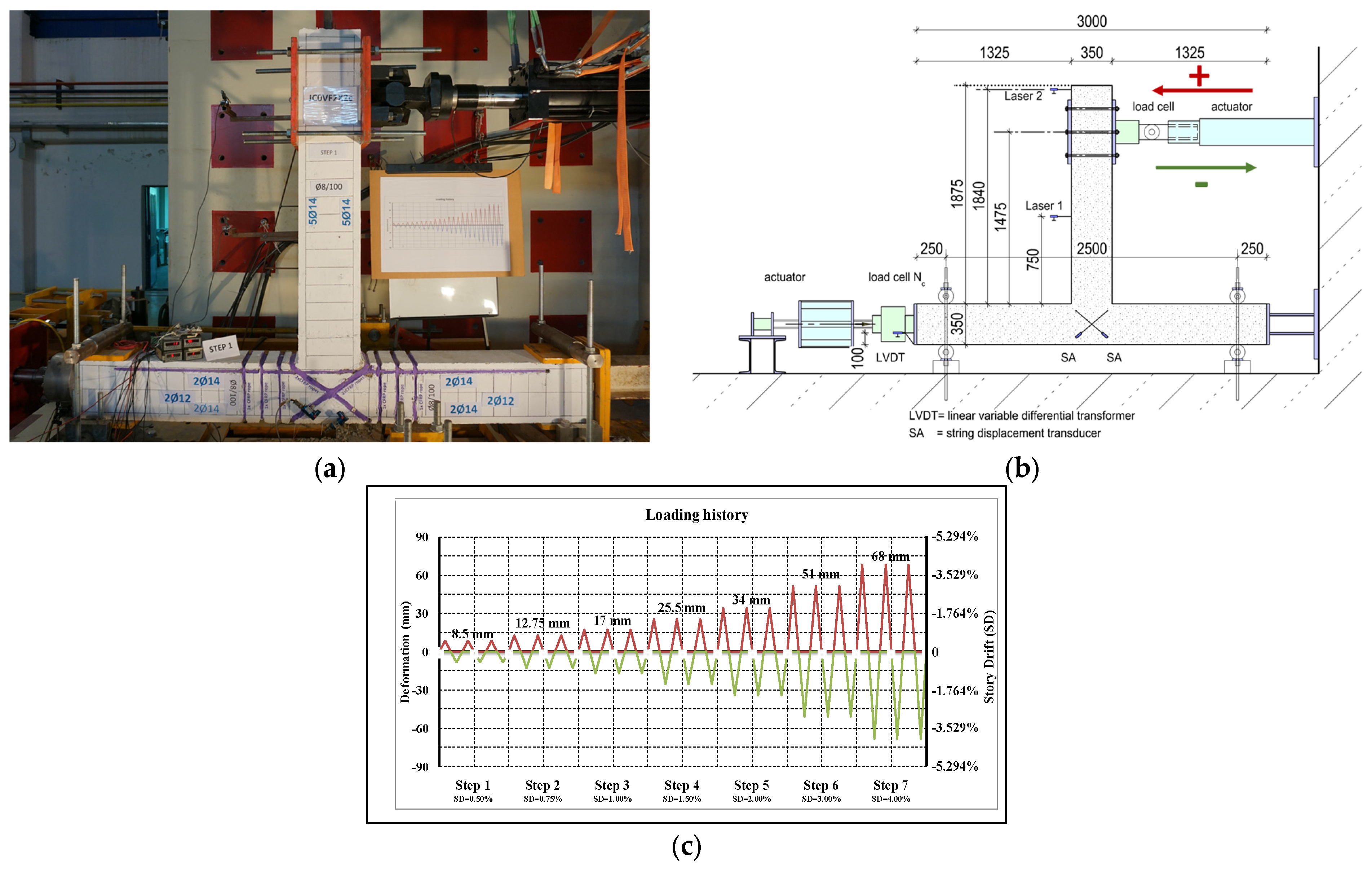
The layout of the test setup and the instrumentation along with a photograph are presented in Figure 5. During the test, the column is positioned horizontally, whereas the cyclic loading is imposed via an actuator acting horizontal at the free end of the beam (Figure 5). Axial compressive loading is constantly applied during the testing procedure to the horizontal column of the specimen.
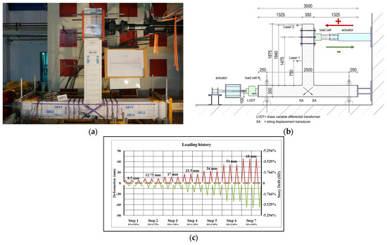
Figure 5.
Testing setup. (a) Specimen JC0V2X2c and instrumentation; (b) layout of the test setup; (c) loading protocol comprises 7 loading steps and each step includes 3 full cycles.
The specimens were tested under the same cyclic loading protocol imposed in a strong wall and rigid floor testing area of the laboratory. The loading is achieved using a double-acting servocontrolled hydraulic actuator with a maximum capacity of 500 kN horizontally fixed on to the rigid wall (Figure 5).
The cyclic loading protocol (Figure 5c) is the same for both specimens, it consists of 7 steps and each step includes 3 full cyclic loadings. The imposed deformations of the steps are presented in mm and in terms of story drifts. Story drift (SD) in the work represents the ratio of the imposed deformation to the length of the beam measured from the loaded point to the centerline of the column. The imposed deformations of the seven cyclic steps are ±8.5 mm, ±12.75 mm, ±17.0 mm, ±25.5 mm, ±34.5 mm, ±51.0 mm, and ±68.0 mm and correspond to story drifts equal to 0.5%, 0.75%, 1.0%, 1.5%, 2.0%, 3.0%, and 4.0%, respectively (Figure 5c).
Measuring instrumentation includes (a) a load cell horizontally fixed to the rigid wall for the imposition of the loading that is simultaneously used for the measuring of displacements and loading of the free end of the beam, (b) string-LVDTs that are diagonally mounted on the joint body of the connection part of the column with the beam for the measurement of the shear deformations of this part of the specimen, and (c) strain gauges sticked on steel bar reinforcements of the column and the beam.
4. Test Results and Discussion
4.1. Evolution of the Damage
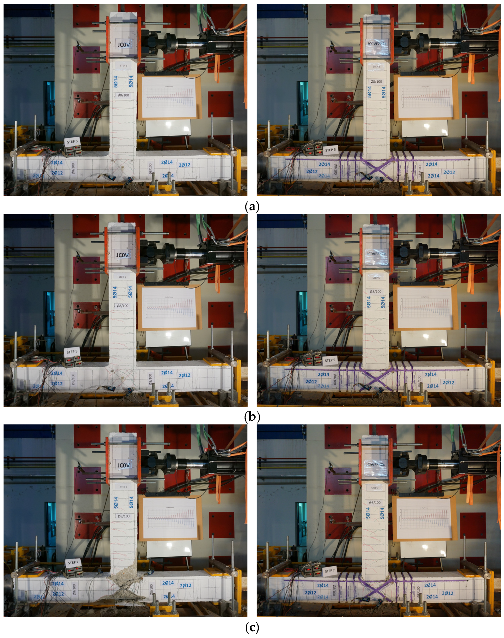
The tested columns, as shown in Figure 2, have no steel stirrups in the body of the connection of the column with the beam. Therefore, the damage is expected to be located in the body of the connection. Figure 6 presents the evolution of the developing cracking system of the tested specimens. In particular, cracking systems of both specimens are presented at the third loading step in Figure 6a, at the fifth loading step in Figure 6b, and at the seventh loading step in Figure 6c. In Figure 6a, it is observed that in the first loading steps cracks appeared only in specimen JC0V, whereas the column of specimen JC0V2X2c along with the connection part remained intact. Further, in the subsequent loading steps, many new cracks appeared in the column and the joint body of the specimen JC0V, as shown in Figure 6b.

Figure 6.
Evolution of the cracking system of the pilot (unstrengthened) specimen JC0V (on the left) and the strengthened specimen JC0VF2X2c with the C-FRP ropes (on the right). Cracking system of both specimens (a) at the 3rd loading step, (b) at the 5th loading step, and (c) at the 7th loading step.
On the other hand, in the column and the joint body of the strengthened specimen JC0V2X2c, only cracks with a crack width equal to 0.1–0.4 mm appeared. In this specimen, flexural cracks with larger width appeared only in the beam. Finally, in the seventh loading step, damage characterized by concrete disorganization and final failure of concrete was observed in the joint body and in parts of the column of the unstrengthened specimen; further, as it can be obtained from the strain gauge measurements (see next Section 5), flexural steel bars of the column developed high tensile strains. In the strengthened specimen, severe cracks appeared in the beam and particularly at the end of the beam near the column where eventually a plastic hinge was formed.
4.2. Hysteretic Response
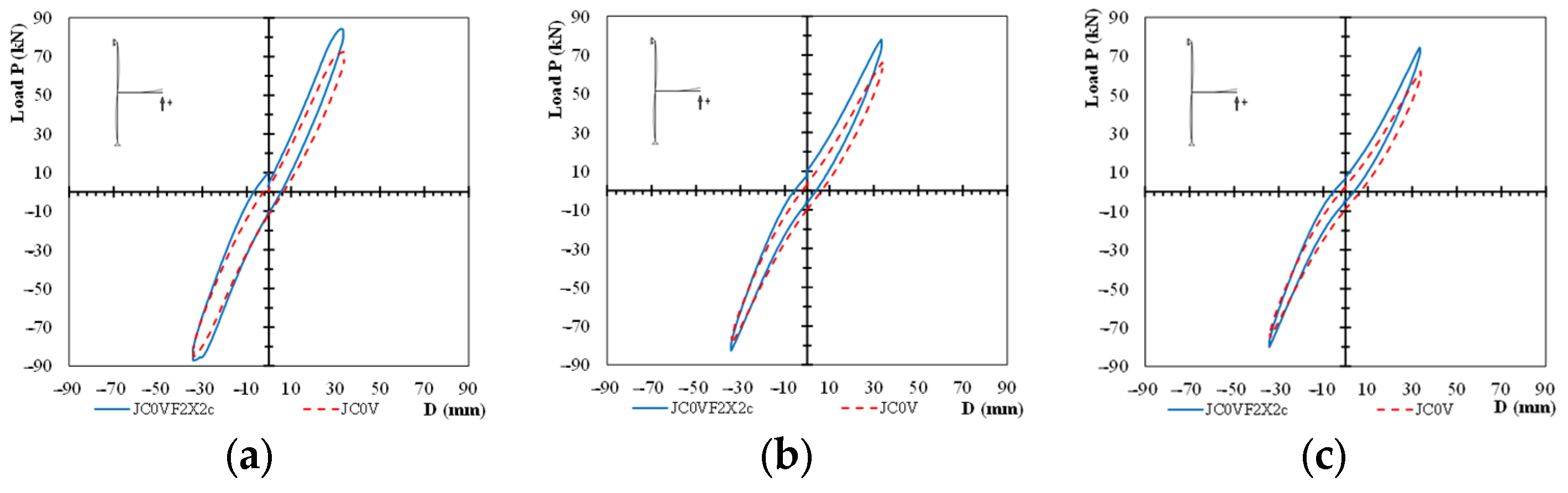
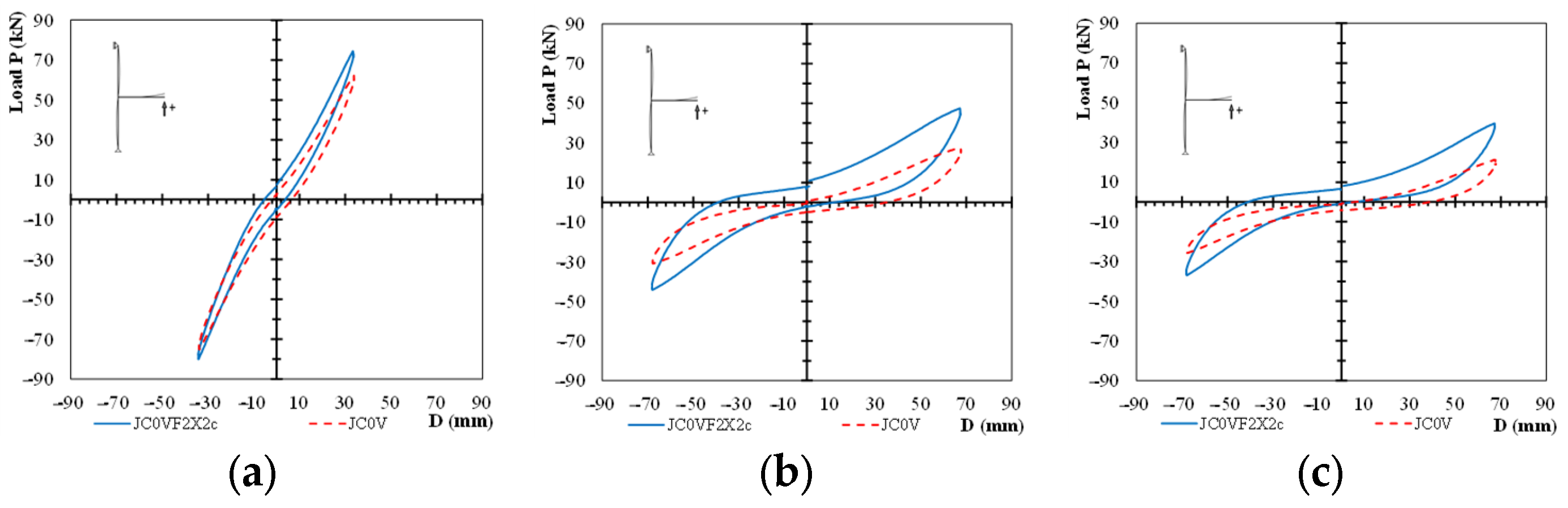
Comparisons of the hysteretic response of the specimens for the fifth and the seventh loading steps are presented in Figure 7 and Figure 8, respectively. In particular, comparisons of the response cycles of the two specimens for the first cycles of the fifth loading step are presented in Figure 7a, for the second cycle of the fifth loading step in Figure 7b, and for the third cycle of the fifth loading step in Figure 7c. From Figure 7, it is observed that the damage level of specimen JC0V is higher than the one of specimen JC0V2X2c since the observed maximum loads per loading cycle are lower than the ones of the strengthened specimen. Further, comparisons of the response cycles of the two specimens are presented for the first cycle of the seventh loading step in Figure 8a, for the second cycle of the seventh loading step in Figure 8b, and for the third cycle of the seventh loading step in Figure 8c. From Figure 8c, it is apparent that the specimen JC0V failed prior to the seventh step. The observed loads of the strengthened specimen are higher than the ones of the unstrengthened specimen; the decrease in the load capacity of the strengthened specimen is mainly attributed to the yielding of the steel reinforcement of the beam.
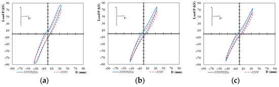
Figure 7.
Fifth loading step. Comparisons of the response cycles of the 5th loading step of the two specimens: (a) the first cycle of the loading step, (b) the second cycle of the loading step, (c) the third cycle of the loading step.
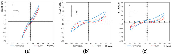
Figure 8.
Seventh loading step. Comparisons of the response cycles of the 7th loading step of the two specimens: (a) the first cycle of the loading step, (b) the second cycle of the loading step, (c) the third cycle of the loading step.
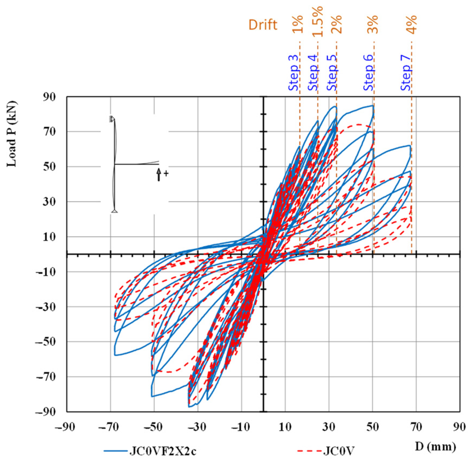
The comparison of the hysteretic responses of the tested specimens for the entire loading procedure is presented in Figure 9.

Figure 9.
Comparison of the hysteretic response cycles of the two specimens. The values of the loading of the strengthened specimen JC0VF2X2c appears to be higher than the corresponding ones of the other specimens in all loading cycles. The differences increase in the 6th and 7th loading steps.
4.3. Envelope Curves
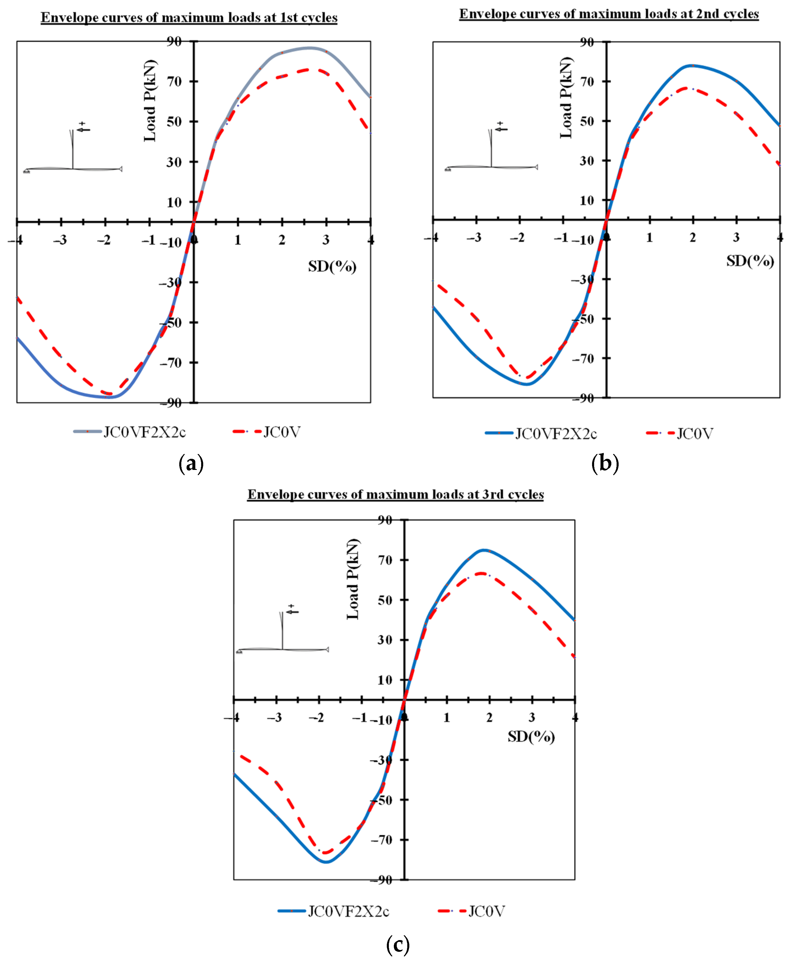
A thorough consideration of the maximum loading observed at each loading step of the tested specimens and, consequently, of the efficacy of the proposed strengthening method in terms of the load capacity and ductility can be obtained through the obtained hysteretic responses. In order to succinctly determine the differences in the observed maximum loads per loading step between the pilot (JC0V) and the strengthened (JC0V2X2c) specimen, a comparative presentation of the envelope curves of the two specimens is shown in Figure 10.
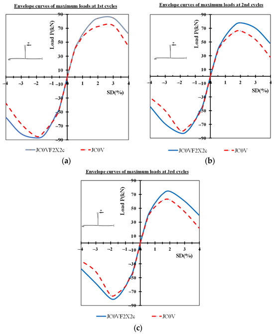
Figure 10.
Comparison of the envelope curves of the tested specimens: (a) envelope curves of the maximum loads at the 1st cycles of each loading step, (b) envelope curves of the maximum loads at the 2nd cycles of each loading step, (c) envelope curves of the maximum loads at the 3rd cycles of each loading step.
In particular, envelope curves of the maximum observed loads of the first cycles of each loading step are shown Figure 10a; further, envelope curves of the maximum loads of the second cycles of each step are shown in Figure 10b; similarly, envelope curves of the maximum loads of the third cycles of each step are shown in Figure 10c.
The damages of the pilot specimen were located in the columns and especially in the joint panel. The developing damage in the joint panel is mainly attributed to an X-shaped shear cracking system that eventually led the specimen to shear failure. On the other hand, the damage of the strengthened column appeared and remained in the beam close to the column, whereas the character of the appeared cracks were purely flexural. Therefore, the observed differences in the cyclic response of the two specimens can mainly attributed to the character of the developing damages.
The observed maximum loads per loading cycle of all loading steps of the tested specimens JC0VF2X2c and JC0V are shown in Table 1. Moreover, the ratios of the maximum loads per loading cycle are also shown in the same Table 1. The differences between the envelope curves of the tested specimens confirm the expected conclusion that the externally applied C-FRP ropes to the column of JC0V2X2c specimen significantly improved the cyclic response of the specimen compared to the response of the other specimen with the unstrengthened column (pilot specimen).

Table 1.
Observed maximum loads per loading cycle and ratio of the maximum loads of the strengthened specimen JC0V2X2c over the corresponding maximum loads of the pilot specimen JC0V.
It is also emphasized that sudden drops of the envelope curves of the tested specimens are observed in Figure 10. These drops are more intense in the unstrengthened specimen since its failure mechanism is mainly of shear character, whereas the final failure mechanism of the strengthened one has a clear flexure character. Further, as it can be noted for the unstrengthened specimens (Figure 10), the sudden drops begin at earlier steps compared to the strengthened one.
4.4. Dissipated Energy
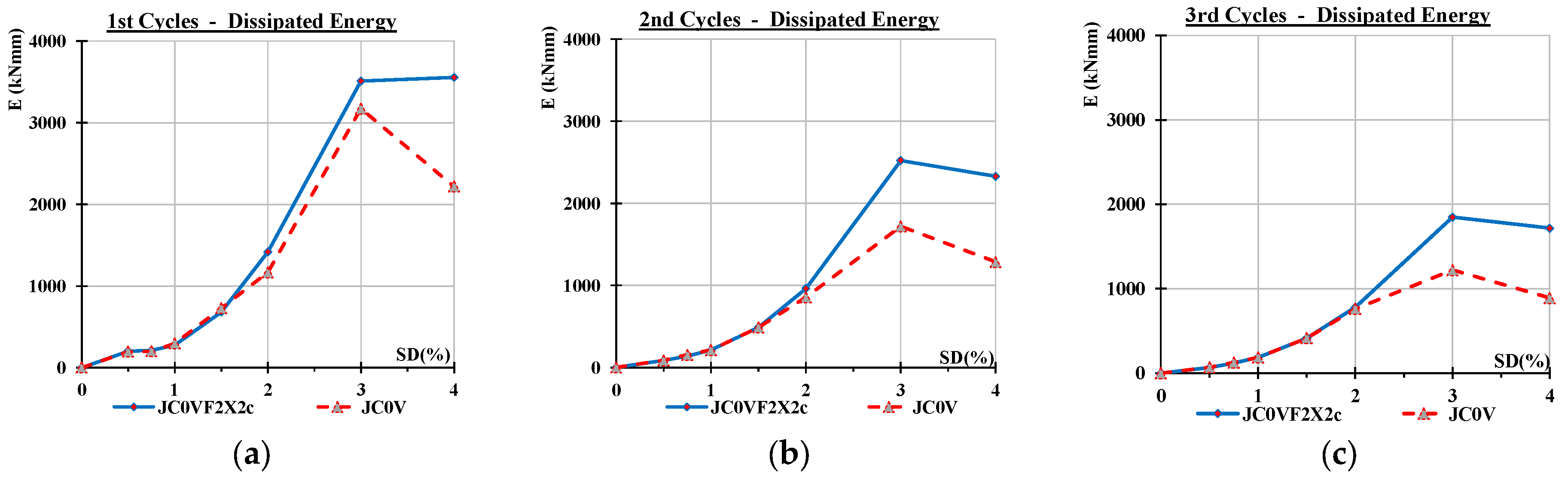
An indicative parameter for the assessment of the overall seismic capacity of the tested columns is the dissipated energy in terms of the area of the cyclic hysteretic response of the tested elements. The comparative presentation of the observed dissipated energy of the tested specimens in terms of the area of the hysteretic cycles is presented in Figure 11. In particular, the dissipated energy of the first cycles, the second cycles, and the third cycles of each loading step are presented in Figure 11a–c, respectively. From the comparisons of Figure 11 between the two specimens, it is apparent that the energy dissipating capacity of the pilot specimen is lower than the capacity of the strengthened specimen. Further, it is noted that the differences increase as the loading becomes higher since the damage of the pilot specimen increases excessively compared to the damage of the strengthened one.
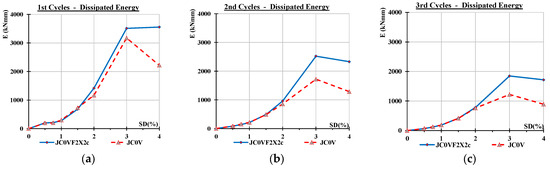
Figure 11.
Comparative presentation of the dissipated energy of the tested specimens in terms of the area of the hysteretic cycles. (a) Dissipated energy of the first cycles of each loading step; (b) dissipated energy of the second cycles of each loading step; (c) dissipated energy of the third cycle of each loading step.
It is noted that the observed improved load capacities of the strengthened specimen compared to the ones of the pilot unstrengthened specimen, as presented in Figure 9 and Figure 10, strongly relate to the improved energy dissipating capacity of the strengthened specimen. It is also emphasized that slippage of the steel bars of the beam has not been observed during the tests due to the well-designed anchorage of the reinforcing bars of the beam in the connection panel and the column of the specimens. Consequently, the an increase in the load capacity in combination with the lack of anchorage slippage, resulted in the increase in energy dissipation.
Furthermore, it is important that the significant increase in the energy dissipation of the strengthened specimen in the sixth and seventh loading steps, compared to the corresponding ones of the pilot specimen, can partly attributed to the nature of the developing failure mechanisms. In the case of the pilot specimen, the damage was mainly of shear character and it was localized in the joint panel; on the other hand, in the strengthened specimen, the column and the joint panel remained almost intact and the damage was clearly of flexural character, and it was developed in the beam near the column joint.
4.5. Comparisons with Traditional Strengthening Methods
The main strengthening methods with traditional reinforcements include the following. (a) Concrete jacketing involves applying an additional layer of reinforced concrete around the existing columns or beams [1,2,3,4]. This method enhances the structural capacity and durability but can significantly increase the stiffness of the strengthened elements, changes the distribution of the seismic loads, and increases the load on the foundation; it usually requires extensive demolition and construction works. (b) Steel plate bonding involves attaching steel plates to the surface of concrete members using adhesive or bolts. This method improves flexural strength and stiffness but may suffer from corrosion issues and requires careful surface preparation, and there are many reservations concerning its effectiveness. (c) External FRP wrapping, often using Glass Fiber-Reinforced Polymer (GFRP) or Carbon Fiber-Reinforced Polymer (CFRP), is another common method. It increases the strength and ductility of structures with minimal impact on the existing load. In general, based on the obtained results, FRP strengthening succeeded in improving the structural behavior of the joints [13,14,15,16]. However, applying U-form jacketing to beams [17] causes inherent restrictions due to the existence of slabs usually existing, and in case of the strengthening of beam–column connections [5,6], geometrical obstacles from the transversal beams also appear. These application problems often limit the effectiveness of the FRP sheets, and, in some cases, render the method unfeasible to apply. Further, the performance of the FRP sheets can be affected by environmental factors and requires proper application techniques.
On the other hand, the main advantages of the application of C-FRP ropes as strengthening reinforcement are as follows. (a) Flexibility and Adaptability: C-FRP ropes can be easily adapted to various shapes and sizes of structural elements, offering a versatile solution for reinforcement. In particular, C-FRP ropes are applied as an external longitudinal reinforcement of the columns to increase the flexural strength; further, C-FRP ropes are also used as external stirrups for the confinement of the critical parts of the columns or the beams in order to improve their concrete strength and the local ductility. Finally, C-FRP ropes are also applied diagonally on the sides of the specimens, providing this method with an X-form external shear reinforcement [41,42,43,44]. (b) Low Weight and Ease of Installation: Compared to traditional methods, C-FRP ropes are lighter and can be installed more quickly, reducing the overall construction time. (c) Corrosion Resistance: Unlike steel reinforcing bars or plates, C-FRP ropes are resistant to environmental degradation, enhancing the longevity of the reinforcement [39]. (d) Long-Term Performance; While current studies show promising results, long-term performance data are still being gathered to fully understand the behavior of C-FRP ropes over extended periods [40].
4.6. Numerical Simulation of the Strengthening Approach
The efficient method of the finite element and, in particular, the Concrete Damage Plasticity (CDP) model as it is implemented in ABAQUS has been employed by the authors [43] in order to provide additional validation to the acquired experimental data. This way, a deeper understanding of the described strengthening approach with the application of C-FRP is achieved, and the results are presented in [43].
The joints were similar with the ones tested herein, and they were either unstrengthened or retrofitted with C-FRP ropes. Based on the results of the study, the following remarks were drawn: (a) The differences between the experimental and numerical results were small, considering the load–displacement curves, the maximum principal stress, and the shear deformations. It shows that the material input in the program and the FE modeling have been accurately performed. (b) The only considerable difference was found in the shear deformation of specimen without C-FRPs. (c) Further, the importance and effectiveness of the application of FRP ropes for the improvement of the seismic response of the joints have also been proved. (d) The cracking patterns of the examined specimens, as predicted using the finite elements in specimens, are very close to those of the experimental ones. This shows that the used CDP can accurately predict the crack propagation in concrete, and it can simulate the concrete’s triaxial behavior accurately. (e) The favorable influence of the ropes is evaluated based on their real characteristics in order to achieve a more realistic prediction of SFRC behavior under compression and tension. The cyclic loading tests of retrofitted joints exhibit improved hysteretic responses in terms of stiffness, load-bearing capacity, deformation, and cracking behavior.
The developed nonlinear FE analysis accurately predicts the overall hysteretic response of joints and the beneficial effect of the added FRP ropes. From the cases examined in this work [43], it is yielded that the values for the maximum loads per loading cycle as predicted from the numerical analysis closely match to the corresponding experimental ones with a divergence up to ±2%. Comparisons between the test and numerical results reveal that the developed nonlinear FE analysis with a smeared crack model that takes into account the tension softening and residual stiffness effect accurately predicts the hysteretic response of realistic concrete joints with steel reinforcement [43].
5. Strain Gauges—Strain of Bar Reinforcements
The measurement of the strain of the steel bar reinforcements of the column and the beam is of vital importance for the assessment of the damage localization. Strain gauges have been mounted on the flexural longitudinal steel bars of the column and beam of the tested specimens (Figure 12).
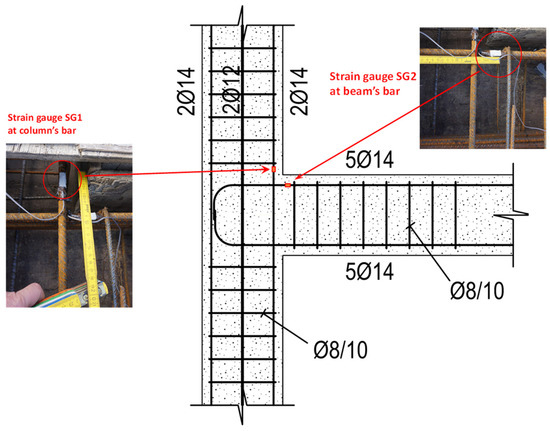
Figure 12.
Two strain gauges, SG1 and SG2, were mounted on each specimen. The strain gauge SG1 was mounted on a flexural reinforcing steel bar of the column, and the strain gauge SG2 was mounted on a flexural reinforcing steel bar of the beam, with both being very close to the edges of the joint panel of the specimen.
Obviously, the yielding of the steel bars of the columns means that the damage is mainly located at the column, whereas the yielding of the steel bars of the beam means that the damage is mainly located at the beam. Thereupon, it is apparent that successful seismic design implies that during a seismic excitation the damage is located in the beams, whereas the columns have to remain intact.
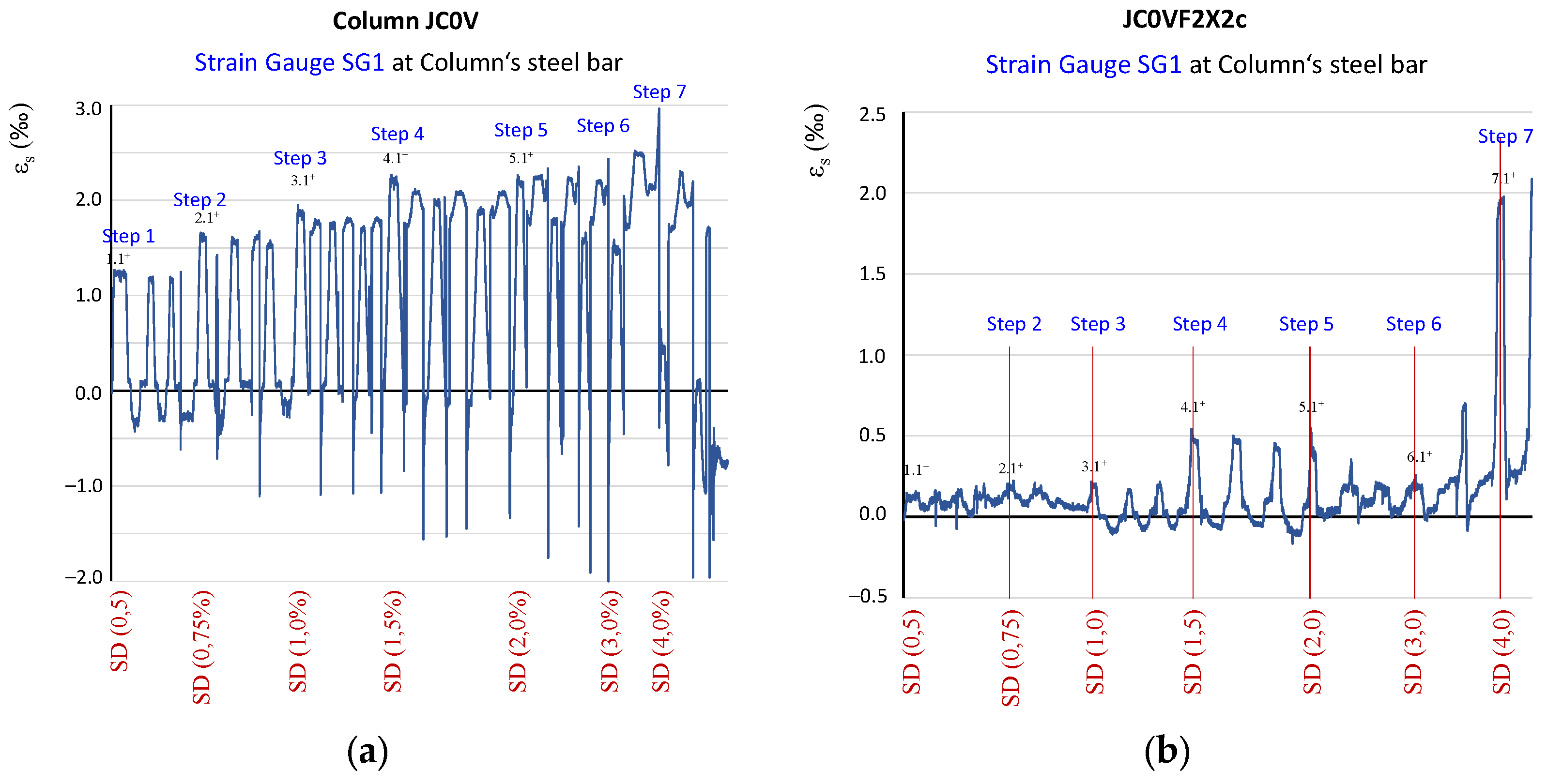
Two strain gauges, SG1 and SG2, have been mounted on each specimen. The strain gauge SG1 was mounted on a flexural reinforcing steel bar of the column (Figure 12), whereas strain gauge SG2 was mounted on a flexural reinforcing steel bar of the beam, with both being very close to the edges of the joint panel of the specimen. The strain values of the steel bars as recorded by the strain gauges SG1 during the testing procedure of the two specimens are presented in Figure 13 for both specimens.
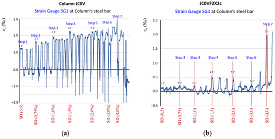
Figure 13.
History of the strain values of the steel bars of the column of the tested specimens. (a) Strain values as recorded from the strain gauge SG1 mounted on a column bar of specimen JC0V and (b) strain values as recorded from the strain gauge SG1 mounted on a column bar of specimen JC0VF2X2c.
In particular, in Figure 13a, the history of the recorded strains of the column steel bar of the pilot specimen JC0V is presented, whereas the history of the recorded strains of the corresponding column steel bar of the strengthened specimen JC0V2X2c is presented in Figure 13b. In the first figure, it can be observed that during the testing procedure, the recorded strain of the flexural steel bar of column JC0V experienced high strain values near the yielding point of 2.5‰ many times. Further, from Figure 13a, it seems that, finally, the strain of the steel bar exceeded the yielding value of 2.5‰, indicating that, in the end of the loading sequence, the yielding of the column took place. On the contrary, in Figure 13b, the strain values of the steel bar of the column experienced low strain values, indicating that the column of the strengthened specimen remained undamaged throughout the testing procedure.
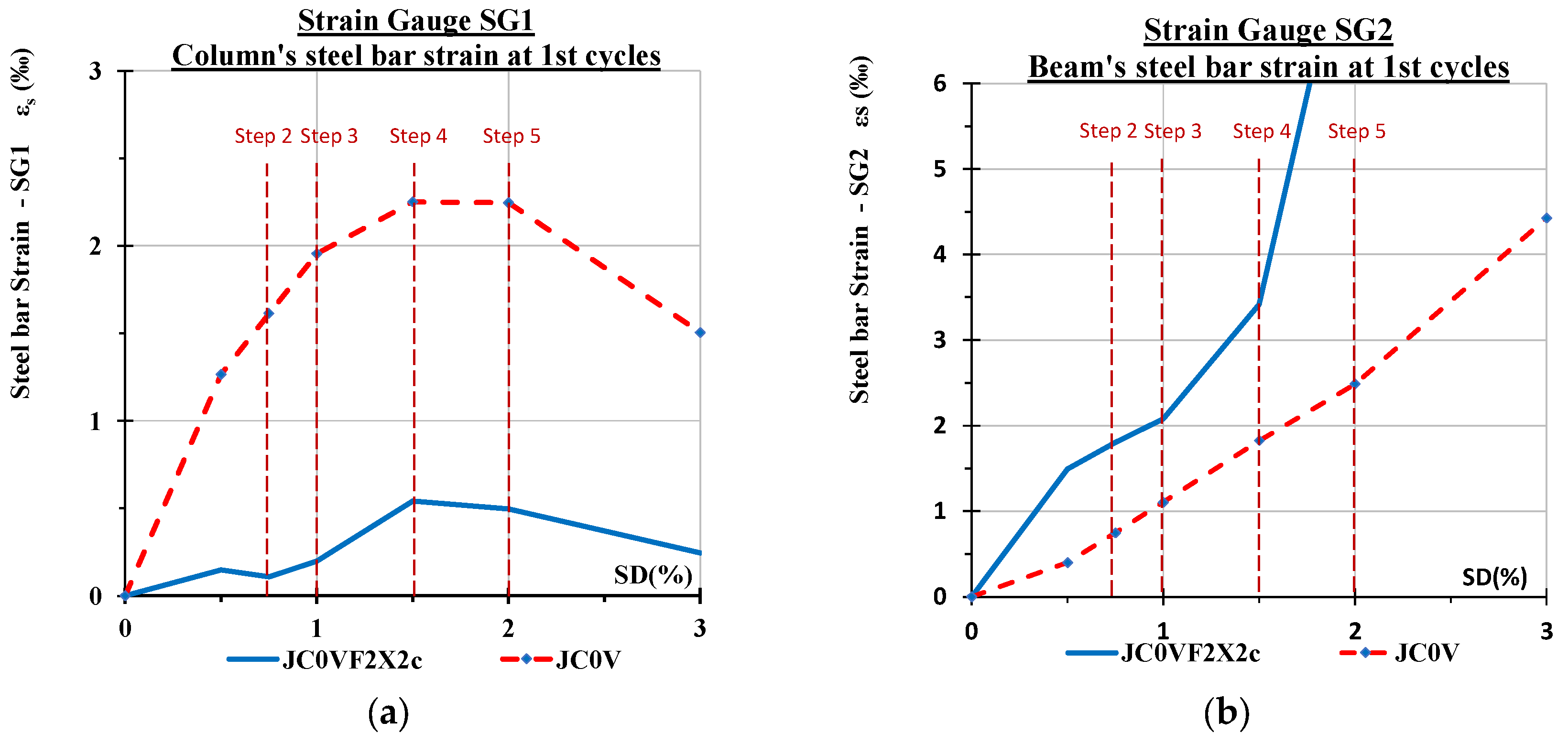
Thereupon, a comparative presentation of the maximum absolute values of the strain of the steel bars per loading step as recorded from the strain gauges SG1 and SG2 mounted on the tested specimens are presented per loading step in Figure 14. In particular, the maximum strain values of strain gauge SG1 mounted on a steel bar of the flexural reinforcement of the column at the edge of the connection panel are presented in Figure 14a for the two tested specimens.
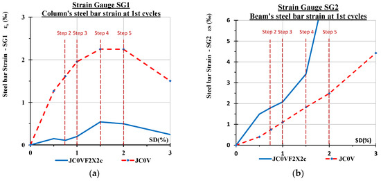
Figure 14.
Comparative presentation of the maximum absolute values of the steel bars strain as recorded from the strain gauges mounted on the tested specimens. (a) Strain gauge SG1 records the strain of the flexural reinforcement of the column at the edge of the connection with the beam; (b) strain gauge SG2 records the strain of the flexural reinforcement of the beam at the edge of the connection with the column.
From this comparison, it is observed that the steel strain of the reinforcement of the column in the case of column JC0V takes high values and strongly indicates that this area suffered severe damage. Moreover, the fact that for higher values of loading deformation after the fifth step the strain of the steel bars suddenly decreases indicates that failure of the concrete takes place.
The maximum strain values of strain gauge SG2 mounted on a steel bar of the flexural reinforcement of the beam at the edge of the connection panel are presented in Figure 14b for the two tested specimens. From this comparison, it is observed that the steel strain of the reinforcement of the beam in the case of the strengthened specimen JC0V2X2c attains high values, indicating that this area suffered damage. It is emphasized that from the strain gauge measurements, it is substantiated that the column and the connection panel of the strengthened specimen remained almost intact, whereas damage and eventually failure is located in the column in the beam of the strengthened specimen.
6. Shear Deformation of the Connection Panel of the Specimens
An important deformation parameter that reflects the level of the damage of the part of the column that connects the column with the beam (joint panel) is its maximum shear deformation during the seismic loading. Therefore, the calculation of the shear deformation of the joint panel at each loading cycle is very important for the assessment of the effectiveness of the applied strengthening technique.
The shear deformations of the joint panel of the tested specimens versus the drift were calculated at each loading step. The comparison of the values of the joint panel shear deformations of the two tested specimens during the testing is an indication for the damage level of the joint panel of each specimen and consequently for the effectiveness of the strengthening technique.
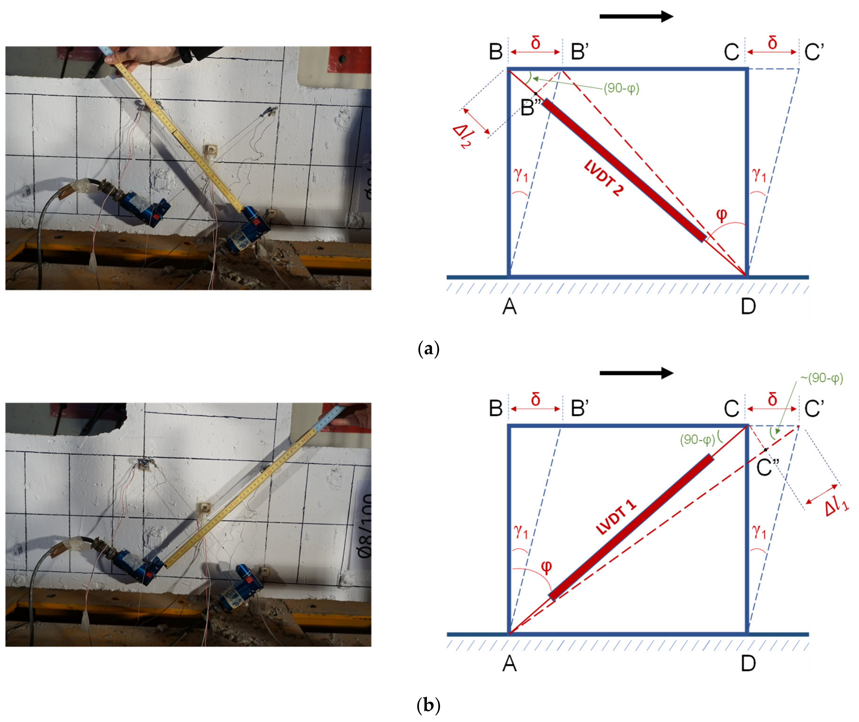
For the calculation of the shear deformations of the joint panel at a loading point of the testing procedure, the values of the diagonal shortening and the diagonal elongation of the panel at the specific moment have to be measured [41,42]. These values were continuously measured and recorded during the testing procedure for both the tested specimens of the presented study. For these measurements, two string displacement transducers (String-LVDTs) were used and diagonally mounted on the connection panel of each specimen. In particular, using the two string-LVDTs, the diagonal shortening (Figure 15a) and the diagonal elongation (Figure 15b) of the panel were continuously measured and recorded.
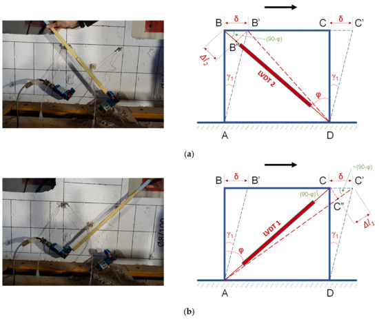
Figure 15.
Shear deformations of the connection body of the column with the beam. Instrumentation and measurement procedure. (a) Diagonally mounted string-LVDT for the measurement of the shortening and (b) diagonally mounted string-LVDT for the measurement of the elongation of the joint panel.
An estimation of the average shear deformation γavg of the connection panel can be calculated based on the following relationship [41]:
where is the elongation of the diagonal string-LVDT, is the shortening of the other diagonal string-LVDT, L is the initial length of the strings of the string-LVDTs, and ϕ is the inclination angle of the diagonals of the joint panel (Figure 15).
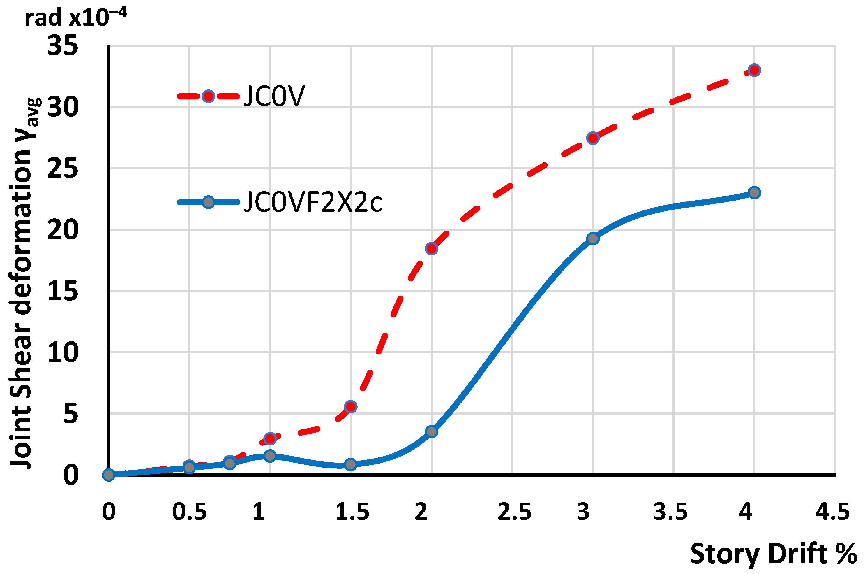
Thus, the diagonal elongations and diagonal shortenings of the joint panel of the tested specimens were measured by the two string LVDTs at each step of the loading procedure. Subsequently, the maximum values of the shear deformations of the joint panel of the two tested specimens were calculated based on Relationship 1. The shear deformations of the specimens are presented per story drift in Figure 16. In this figure, the absolute values of the maximum shear deformations of the joint panel of the strengthened specimen JC0V2X2c are compared with the corresponding values of the shear deformations of the specimen JC0V per loading step and drift. It is apparent that the maximum shear deformations of the connection panel of the strengthened specimen JC0VF2X2c are lower than the corresponding ones of the pilot unstrengthened specimen JC0V. It is a strong indication that the strengthening technique increases the strength and the stiffness capacity of the column and decreases the deformations and the damages in comparison with the ones of the specimen JC0V.

Figure 16.
Absolute values of the maximum shear deformations of the joint panel of the tested specimens per loading step and drift. It is apparent that the maximum shear deformations of the connection panel of the strengthened specimen JC0VF2X2c are lower than the ones of the pilot specimen JC0V without strengthening.
7. Concluding Remarks
The efficacy of the application of C-FRP ropes as an externally mounted reinforcement for the strengthening of the RC columns and the connection part of the columns with the beams is experimentally studied with real-scale specimens. The strengthening approach can easily be applied even in structures with complicated configuration without any restraints due to the structural geometry. The application of the C-FRP ropes does not change the mass of the structure and, consequently, the dynamic characteristics of the building remain the same.
From the comparative examination of the strengthened specimen with the specimen without strengthening (pilot specimen) the following conclusions are made:
- Both specimens are tested under the same cyclic loading procedure that comprises seven steps and each step includes three full loading cycles. The maximum loads of the strengthened specimen at the three loading cycles of the seventh step were 40%, 72%, and 87% higher than the corresponding ones of the unstrengthened specimen.
- From the observed dissipated energy of the tested specimens, it is apparent that the energy dissipating capacity of the pilot specimen is lower than the capacity of the strengthened specimen.
- The systematic comparative study of the shear deformation of the connection panel of the tested specimens proved that the externally applied X-shaped C-FRP ropes kept the column and the connection panel intact and substantially reduced its shear deformations even in high drifts. The measured shear deformations of the joint panel of the pilot (unstrengthened) specimen at the sixth and the seventh steps were 43% and 44% higher than the corresponding ones of the strengthened specimen.
- Finally, it is emphasized that measured shear deformations of the joint panel and the strain gauge measurements have substantiated that the column and the connection panel of the strengthened specimen remained almost intact, whereas damage and eventually failure have been located in the column and the joint panel of the pilot specimen.
Author Contributions
Conceptualization, C.K. and E.G.; methodology, C.K. and E.G.; validation C.K. and E.G.; formal analysis, C.K. and E.G.; investigation, C.K. and E.G.; resources, E.G.; data curation, E.G.; writing—original draft preparation, C.K.; writing—review and editing, C.K.; visualization, E.G.; supervision, C.K.; project administration, C.K.; funding acquisition, E.G. All authors have read and agreed to the published version of the manuscript.
Funding
This research received no external funding.
Institutional Review Board Statement
Not applicable.
Informed Consent Statement
Not applicable.
Data Availability Statement
Data available on request.
Acknowledgments
We would like to thank the company SIKA HELLAS SA for the supply and free disposal of the needed FRP materials.
Conflicts of Interest
The authors declare no conflicts of interest.
References
- Engindeniz, M.; Kahn, L.F.; Zureick, A.-H. Repair and strengthening of reinforced concrete beam-column joints: State of the art. ACI Struct. J. 2005, 102, 1–14. [Google Scholar]
- Raza, S.; Khan, M.K.I.; Menegon, S.J.; Tsang, H.-H.; Wilson, J.L. Strengthening and Repair of Reinforced Concrete Columns by Jacketing: State-of-the-Art Review. Sustainability 2019, 11, 3208. [Google Scholar] [CrossRef]
- Kalogeropoulos, G.I.; Tsonos, A.-D.; Konstantinidis, D.; Iakovidis, P.E. Earthquake-resistant rehabilitation of existing RC structures using high-strength fiber-reinforced concrete Jackets. Earthq. Struct. 2019, 17, 115–129. [Google Scholar]
- Karayannis, C.G.; Chalioris, C.E.; Sirkelis, G.M. Local retrofit of exterior RC beam-column joints using thin RC jackets—An experimental study. Earthq. Eng. Struct. Dyn. 2008, 37, 727–746. [Google Scholar] [CrossRef]
- Karayannis, C.G.; Golias, E. Full scale tests of RC joints with minor to moderate damage repaired using C-FRP sheets. Earthq. Struct. 2018, 15, 617–627. [Google Scholar] [CrossRef]
- Karayannis, C.G.; Sirkelis, G.M. Strengthening and rehabilitation of RC beam-column joints using FRP jacketing and epoxy resin injections. J. Earthq. Eng. Struct. Dyn. 2008, 37, 769–790. [Google Scholar] [CrossRef]
- Mostofinejad, D.; Hajrasouliha, M. 3D Beam–Column Corner Joints Retrofitted with X-Shaped FRP Sheets Attached via the EBROG Technique. Eng. Struct. 2019, 183, 987–998. [Google Scholar] [CrossRef]
- Pohoryles, D.A.; Melo, J.; Rossetto, T.; Varum, H.; Bisby, L. Seismic Retrofit Schemes with FRP for Deficient RC Beam-Column Joints: State-of-the-Art Review. J. Compos. Constr. 2019, 23, 03119001. [Google Scholar] [CrossRef]
- Realfonzo, R.; Napoli, A.; Pinilla, J. Cyclic behavior of RC beam-column joints strengthened with FRP. Constr. Build. Mater. 2014, 54, 282–297. [Google Scholar] [CrossRef]
- De Risi, M.T.; Del Vecchio, C.; Ricci, P.; Ludovico, M.D.; Prota, A.; Verderame, G.M. Light FRP Strengthening of poorly detailed reinforced concrete exterior beam-column joints. J. Compos. Constr. 2020, 24, 04020014. [Google Scholar] [CrossRef]
- Bossio, A.; Fabbrocino, F.; Lignola, G.P.; Prota, A.; Manfredi, G. Simplified Model for Strengthening Design of Beam–ColumnInternal Joints in Reinforced Concrete Frames. Polymers 2015, 7, 1732–1754. [Google Scholar] [CrossRef]
- Tsonos, A.G. Ultra-High-Performance Fiber Reinforced Concrete: An Innovative Solution for Strengthening Old R/C Structures and for Improving the FRP Strengthening Method. WIT Trans. Eng. Sci. 2009, 64, 12. [Google Scholar]
- Del Vecchio, C.; Di Ludovico, M.; Balsamo, A.; Prota, A.; Manfredi, G.; Dolce, M. Experimental Investigation of Exterior RC Beam-Column Joints Retrofitted with FRP Systems. J. Compos. Constr. 2014, 18, 04014002. [Google Scholar] [CrossRef]
- Hadi, M.N.S.; Tran, T.M. Seismic Rehabilitation of Reinforced Concrete Beam-Column Joints by Bonding with Concrete Covers and Wrapping with FRP Composites. Mater. Struct. 2016, 49, 467–485. [Google Scholar] [CrossRef]
- Faleschini, F.; Gonzalez-Libreros, J.; Zanini, M.A.; Hofer, L.; Sneed, L.; Pellegrino, C. Repair of Severely-Damaged RC Exterior Beam-Column Joints with FRP and FRCM Composites. Compos. Struct. 2019, 207, 352–363. [Google Scholar] [CrossRef]
- Al-Salloum, Y.A.; Almusallam, T.H. Seismic Response of Interior RC Beam-Column Joints Upgraded with FRP Sheets. I: Experimental Study. J. Compos. Constr. 2007, 11, 575–589. [Google Scholar] [CrossRef]
- Chalioris, C.E.; Zapris, A.G.; Karayannis, C.G. U-jacketing applications of fiber-reinforced polymers in reinforced concrete t-beams against shear-tests and design. Fibers 2020, 8, 13. [Google Scholar] [CrossRef]
- Dalfre, G.M.; Barros, J.A.O. NSM technique to increase the load carrying capacity of continuous RC slabs. Eng. Struct. 2013, 56, 137–153. [Google Scholar] [CrossRef]
- Yu, F.; Feng, C.; Fang, Y.; Liu, Q.; Hu, Y.; Bu, S. Experimental study on low-strength concrete joint core strengthened with steel meshes for connecting PFCC column and RC beam. Adv. Struct. Eng. 2021, 24, 797–814. [Google Scholar] [CrossRef]
- Ruiz-Pinilla, J.G.; Cladera, A.; Pallares, F.J.; Calderon, P.A.; Adam, J.M. Joint strengthening by external bars on RC beam-column joints. J. Build. Eng. 2022, 45, 103445. [Google Scholar] [CrossRef]
- Spadea, G.; Bencardino, F.; Sorrenti, F.; Swamy, R.N. Structural Effectiveness of FRP Materials in Strengthening RC Beams. Eng. Struct. 2015, 99, 631–641. [Google Scholar] [CrossRef]
- Karayannis, C.G.; Kosmidou, P.-M.K.; Chalioris, C.E. Reinforced concrete beam with carbon-fiber-reinforced polymer bars—Experimental study. Fibers 2018, 6, 99. [Google Scholar] [CrossRef]
- Murad, Y.Z.; Alseid, B.H. Retrofitting interior RC beam-to-column joints subjected to quasi-static loading using NSM CFRP ropes. Structures 2021, 34, 4158–4168. [Google Scholar] [CrossRef]
- Karayannis, C.G.; Golias, E. Strengthening of deficient RC joints with diagonally placed C-FRP ropes. Earthq. Struct. 2021, 20, 123–132. [Google Scholar] [CrossRef]
- Rousakis, T.C.; Panagiotakis, G.D.; Archontakis, E.E.; Kostopoulos, A.K. Prismatic RC columns externally confined with FRP sheets and pre-tensioned vecch fiber ropes under cyclic axial load. Compos. Part B 2019, 163, 96–106. [Google Scholar] [CrossRef]
- Rousakis, T.C. Hybrid confinement of concrete by fiber-reinforced polymer sheets and fiber ropes under cyclic axial compressive loading. J. Comp. Constr. 2013, 17, 732–743. [Google Scholar] [CrossRef]
- Karabini, M.; Rousakis, T.C.; Golias, E.; Karayannis, C.G. Seismic tests of full scale reinforced concrete T joints with light external continuous rope strengtheneing – Joint deterioration and failure assessment. Materials 2023, 16, 2718. [Google Scholar] [CrossRef]
- Chalioris, C.E.; Kosmidou, P.-M.K.; Papadopoulos, N.A. Investigation of a new strengthening technique for RC deep beams using carbon FRP ropes as transverse reinforcements. Fibers 2018, 6, 52. [Google Scholar] [CrossRef]
- Golias, E.; Zapris, A.G.; Kytinou, V.K.; Kalogeropoulos, G.I.; Chalioris, C.E.; Karayannis, C.G. Effectiveness of the novel rehabilitation method of seismically damaged rc joints using c-frp ropes and comparison with widely applied method using c-frp sheets—Experimental investigation. Sustainability 2021, 13, 6454. [Google Scholar] [CrossRef]
- Elsanadedy, H.M.; Abbas, H.; Tarek, H.; Almusallam, T.H.; Al-Salloum, Y.A. Organic versus inorganic matrix composites for bond-critical strengthening applications of RC structures—State-of-the-art review. Compos. Part B 2019, 174, 106947. [Google Scholar] [CrossRef]
- Davalos, J.F.; Chen, Y.; Ray, I. Effect of FRP bar degradation on interface bond with high strength concrete. Cem. Concr. Compos. 2008, 20, 722–730. [Google Scholar] [CrossRef]
- Lu, X.Z.; Ye, L.P.; Teng, J.G.; Jiang, J.J. Bond–slip models for FRP sheets/plates bonded to concrete. Eng. Struct. 2005, 27, 920–937. [Google Scholar] [CrossRef]
- Lorenzis, L.D.; Miller, B.; Nanni, A. Bond of fiber-reinforced polymer laminates to concrete. ACI Mater. J. 2001, 98, 256–264. [Google Scholar]
- Blaschko, M. Bond behaviour of CFRP strips glued into slits. Cem. Concr. Compos. 2003, 25, 493–502. [Google Scholar]
- Karayannis, C.G.; Chalioris, C.E. Strengthening of Shear T–Beams Using Carbon FRP. In Proceedings of the 1st International Conference on Concrete Repair, St–Malo, France, 15–17 July 2003; pp. 775–782. [Google Scholar]
- Cao, S.Y.; Teng, J.G.; Smith, S.T. Bond behavior of FRP strips bonded to concrete. J. Compos. Constr. 2007, 11, 120–128. [Google Scholar]
- Gamage, J.C.P.H.; Yamaguchi, H.; Katoh, H. Debonding of FRP sheets in strengthened concrete flexural members. Cem. Concr. Compos. 2006, 28, 299–312. [Google Scholar]
- Al-Madhkour, A.; El-Gamal, S.; Younis, M. Durability of CFRP composites under different environmental conditions. J. Compos. Constr. 2010, 14, 723–731. [Google Scholar]
- Kim, J.; Lee, S.; Ryu, G. Aging behavior of CFRP composites exposed to environmental conditions. Compos. Struct. 2015, 122, 464–473. [Google Scholar]
- Zhang, Y.; Liu, W.; Chen, X. Performance of CFRP composites in extreme environmental conditions. Constr. Build. Mater. 2018, 159, 280–291. [Google Scholar]
- Karayannis, C.; Golias, E.; Kalogeropoulos, G.I. Influence of carbon fiber-reinforced ropes applied as external diagonal reinforcement on the shear deformation of RC joints. Fibers 2022, 10, 28. [Google Scholar] [CrossRef]
- Karayannis, C.G.; Golias, E.; Naoum, M.C.; Chalioris, C.E. Efficacy and damage Diagnosis of reinforced concrete columns and joints strengthened with FRP ropes using piezoelectric transducers. Sensors 2022, 22, 8294. [Google Scholar] [CrossRef] [PubMed]
- Golias, E.; Touratzidis, P.; Karayannis, C. Seismic response of RC beam-column joints strengthened with FRP ropes, using 3D finite element. Verification with real scale tests. CivilEng 2024, 5, 395–419. [Google Scholar] [CrossRef]
- Karayannis, C.; Golias, E. Full-scale experimental testing of RC beam-column joints strengthened using CFPR ropes as external reinforcement. Eng. Struct. 2022, 250, 113305. [Google Scholar] [CrossRef]

Disclaimer/Publisher’s Note: The statements, opinions and data contained in all publications are solely those of the individual author(s) and contributor(s) and not of MDPI and/or the editor(s). MDPI and/or the editor(s) disclaim responsibility for any injury to people or property resulting from any ideas, methods, instructions or products referred to in the content. |
© 2024 by the authors. Licensee MDPI, Basel, Switzerland. This article is an open access article distributed under the terms and conditions of the Creative Commons Attribution (CC BY) license (https://creativecommons.org/licenses/by/4.0/).