Article

Research and Application of the Synergistic Support System of “LDAGF” in an Extremely Soft and Fragile Fully Mechanized Caving Face Roadway

1
School of Mining Engineering, Anhui University of Science and Technology, Huainan 232001, China
2
China Coal Xinji Energy Limited Liability Company, Huainan 232001, China
3
Research Center for Carbon Neutrality in Coal Cities, Huainan Normal University, Huainan 232038, China
4
School of Engineering Science, University of Science and Technology of China, Hefei 230022, China
5
State Key Laboratory of Mining Response and Disaster Prevention and Control in Deep Coal Mines, Anhui University of Science and Technology, Huainan 232001, China
*
Author to whom correspondence should be addressed.
Appl. Sci. 2024, 14(18), 8485; https://doi.org/10.3390/app14188485
Submission received: 15 August 2024 / Revised: 14 September 2024 / Accepted: 18 September 2024 / Published: 20 September 2024
(This article belongs to the Special Issue Advances and Challenges in Rock Mechanics and Rock Engineering)

Abstract

:
This study aims to alleviate the serious deformation of surrounding rock (SR) in an extremely soft and fragile fully mechanized caving face roadway (ESFFMCFR, the 8# coal seam, Huaibei mining area) under a conventional support. Laboratory tests of roadway SR were conducted. The results show that in this coal seam, the extremely soft and fragile coal body has a high clay mineral content, so it is of low strength and breaks and softens easily. With reference to the mechanical tests on coal and rock mass around the coal seam and the monitoring results of roadway deformation, the roadway deformation is mainly caused by the development of fractures in the roadway SR, the separation of the support body and SR and the loose supporting structure. Considering the engineering environment and deformation characteristics of SR in the ESFFMCFR (the 8# coal seam, Huaibei mining area), this study proposed a synergistic support system of “lowering, drilling, anchoring, grouting and flatting (LDAGF)” for the ESFFMCFR based on the synergistic mechanism of support and SR under the basic principles of synergetics. Specifically, the synergistic support system of “LDAGF” includes the following measures: floor breaking and side lowering, bolt advance support, anchor cable support, advance water injection and grouting and flat-roof U-shaped steel shed support. Furthermore, this synergistic support system was applied on the ESFFMCFR in the 8# coal seam of Xinhu and Guobei coal mines, Huaibei mining area. The on-site application results reveal that when the synergistic support system is adopted, the maximum subsidence values in the above roadway roofs are 117 mm and 121 mm and the maximum displacement values of the two sides are 66 mm and 74 mm, respectively, which proves an excellent support effect. The synergistic support system, which can effectively control the serious deformation of the SR in ESFFMCFRs and ensure long-term stability and safety of the roadways, is suitable for the support of ESFFMCFRs and is of great guiding significance for roadways of the same type.

1. Introduction

To reduce the difficulty in excavation and improve production efficiency, mining roadways with a short service life are generally arranged in low-strength coal strata and mostly adopt rectangular sections [1]. Under the conventional anchorage support, tensile stress distribution areas appear on the surface of roadways with rectangular sections as a result of the shape of roadway sections, the morphological characteristics of anchorage body and the secondary stress distribution during excavation [2]. Meanwhile, the anchorage system has a limited effect on the shoulder angle of the roadway. The roadway roof and the anchorage bodies at the two sides are independent of each other, failing to achieve roof–side synergy [3]. In addition, affected by the geological condition of mining, the two sides and roof of the extremely soft and fragile fully mechanized caving face roadway (ESFFMCFR) are composed of extremely soft and fragile coal bodies. An increasing mining depth leads to a high ground stress. Under such a special geological condition, it is difficult to maintain a rectangular section, and the conventional anchor support systems for roadways often fail. Thus, steel sections is required for maintenance and frequent renovation. Roof accidents occur at a rising frequency [4]. The support of the ESFFMCFR requires much effort, which seriously affects the recovery efficiency in fully mechanized caving faces.
An et al. [5] studied the failure mechanism of ESFFMCFR with high ground stress; they thought that an “inverted trapezoid”-shaped plastic zone was formed in its roof coal, and stressed the importance of a cable-stayed anchor cable support. Xu et al. [6] believed that the root causes of the serious deformation of the ESFFMCFR lay in the weak roof supporting structure, weak synergistic control of the roof and sides as well as high tensile stress in the middle of the roof. Wang et al. [7] studied the stress and deformation characteristics of surrounding rock (SR) in a fully mechanized caving face roadway (FMCFR) under different influencing factors, obtained the relationships between SR stress distribution and influencing factors, and considered that the preload of anchor bolts and cables should form a compressive stress area where they are connected and superimposed with each other. Through similar simulation tests, Wang et al. [8] found that the support of an arch-shaped integral anchor structure in roadways could effectively control the serious deformation of roadway SR. By means of discontinuous deformation analysis, Ma et al. [9] analyzed the deformation and failure characteristics of straight-wall semi-circular arch roadways in large-dip-angle soft and broken thick coal seams under different support conditions. By analyzing the mechanism of bolt support, Cao et al. [10] put forward a one-time permanent support for a high pre-stressed and strong support system to control serious SR deformation in complex and difficult roadways of the coal mine. In summary, studies on roadway support in soft and broken thick coal seams have mainly focused on the control technologies for roadway SR, such as anchor bolts and cables, bolt mesh shotcrete and U-shaped steel shed support. However, for the ESFFMCFR, the above support measures of anchor bolts (cables) and U-shaped steel sheds with an increased density or strength not only fail to effectively support roadways, but also waste a lot of materials.
To sum up, current conventional roadway support technologies have certain limitations, failing to effectively control the deformation and failure of SR in ESFFMCFRs. The support technology for ESFFMCFRs requires further research [11,12,13,14,15,16,17,18,19,20,21,22]. This study took an ESFFMCFR as the research object. First, the hydraulic characteristics of extremely soft and fragile coal were studied by laboratory tests. With the aid of mechanical tests of coal and rock mass and on-site monitoring results, the failure mechanism and support measures for SR of the ESFFMCFR were explored. On this basis, a synergistic support system of “LDAGF” for ESFFMCFR was established through technical measures of floor breaking and side lowering of the roadway, bolt advance support, anchor cable support, advance water injection and grouting and flat roof U-shaped steel shed support. Finally, it was successfully applied to the ESFFMCFR in Guobei Coal Mine and Xinhu Coal Mine to ensure the long-term stability and safety of the SR and the support structure. The research results can provide a new insight into support design for ESFFMCFRs.

2. Engineering Background

2.1. Engineering Profile

The 8# coal seam is the main mining coal seam of Luling (LL) Coal Mine, Zhuxianzhuang (ZXZ) Coal Mine, Qingdong (QD) Coal Mine, Guobei (GB) Coal Mine, Yuanyi (YY) Coal Mine, Tongting (TT) Coal Mine, Zouzhuang (ZZ) Coal Mine and Xinhu (XH) Coal Mine in Huaibei mining area. On the whole, it is of a wide and gentle monoclinic structure, with a stratigraphic dip of 255–285° and a dip angle of 14–25° (20° on average). Coal in the 8# coal seam, which belongs to semi-bright to bright briquette, has the following features: black, powdered, locally broken blocks, glass luster and developed endogenous fractures. The seam is 8.2–10.2 m thick (8.2 m on average), locally containing 1–2 layers of gangue. The gangue, which is 0–1.1 m thick in total, is mainly composed of siltstone and also locally comprises mudstone. The 8# coal seam is extremely soft and fragile, with low strength. The roadway for recovering the coal seam is arranged along the floor, the floor plate is unsupported. In the past, the excavation of the FMCFR in the 8# coal seam adopted a U-shaped steel shed support. However, the two sides of the roadway are of low strength, so the legs of the U-shaped steel sheds cannot take root, resulting in a poor passive support effect of the steel sheds and serious deformation of the roadway floor at the two sides. Moreover, the coal body of the roadway roof is extremely soft and fragile, so the U-shaped steel sheds cannot effectively support the roof, leading to serious air leakage, roof caving and overall serious roadway deformation (Figure 1). These problems not only bring great difficulty to roof management, but also induce hazards of spontaneous combustion of gas and coal. Roadways are often repaired after excavation, leaving much hidden danger. In addition, coal in front of the ESFFMCFR in thick seams experiences serious rib spalling, which affects the normal excavation. Resultantly, under the U-shaped steel shed support, the ESFFMCFR in the 8# coal seam is excavated at an average monthly amount of merely 50–60 m, which seriously restricts the safe and efficient production of coal mines.

2.2. Laboratory Tests

To better reveal the physicochemical and mechanical properties of extremely soft and fragile thick coal seams, cores were drilled around the excavated roadways of the 8# coal seam in the LL, QD, GB and XH coal mines, respectively. Coal and rock blocks at the head in the corresponding coal seam were collected for laboratory tests.

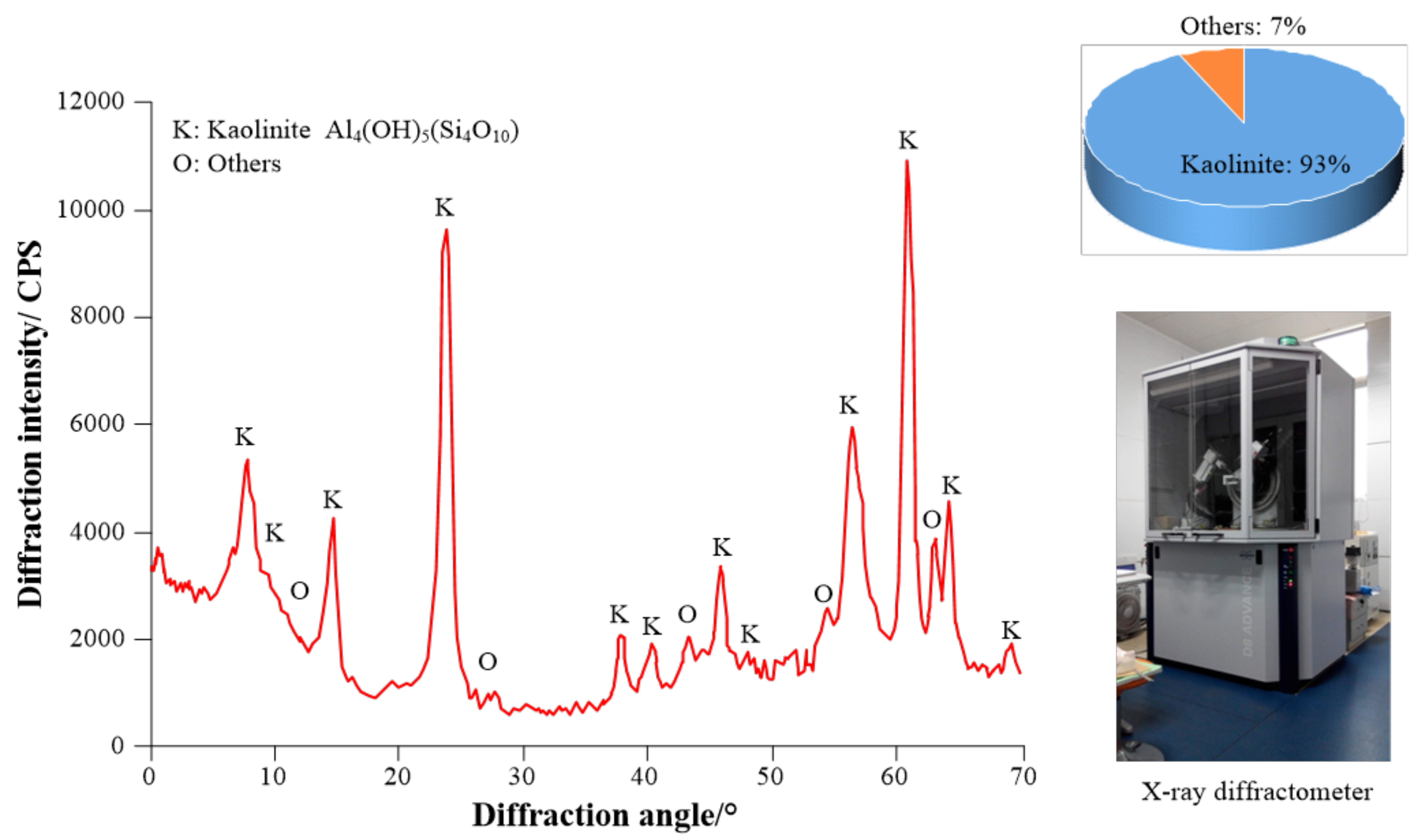
2.2.1. X-ray Diffraction Analysis

Deformation of SR in the ESFFMCFR is dominated by coal deformation. The raw coal samples from the excavated roadways of the 8# coal seam in the LL, QD, GB and XH coal mines were selected for X-ray diffraction tests. Their mineral compositions and contents were analyzed (Figure 2). The mineral composition contents are shown in Table 1.
For the ESFFMCFR in the 8# coal seam, the main associated mineral is kaolinite (content about 10%). As a clay mineral with weak water resistance, kaolinite expands and collapses easily when encountering water, characterized by notable collapsibility. Hence, the coal body is extremely soft and fragile, which makes the FMCFR in thick coal seams more prone to deformation, failure and instability.

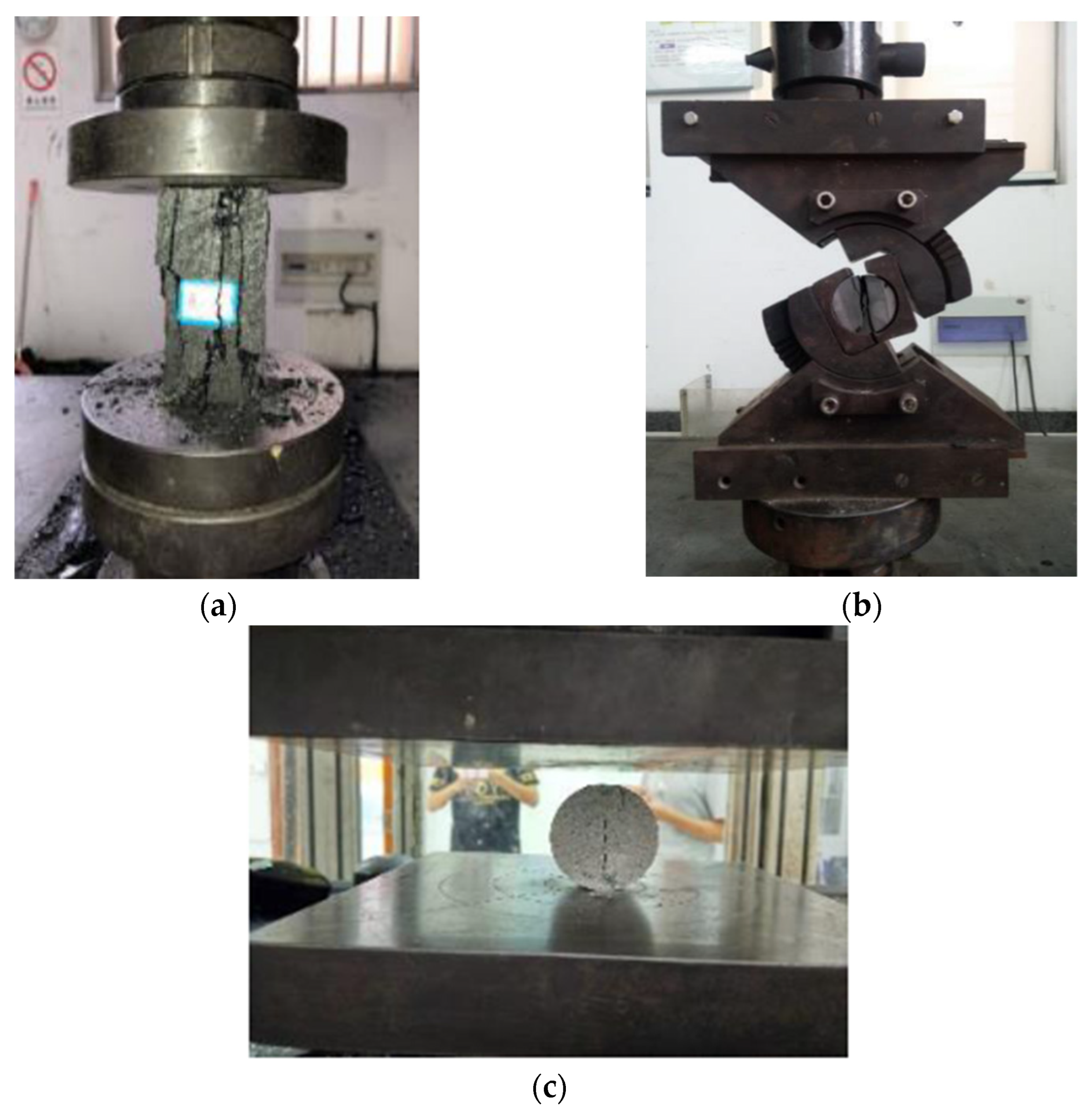
2.2.2. Strength Experiments for Coal and Rock Mass

An ESFFMCFR is generally excavated along the floor, and the roof and two sides share an identical coal structure. Therefore, the mudstone layers of the excavated roadway roof and floor and the 8# coal seam in the LL, QD, GB and XH coal mines were sampled on-site. There were 50 coal seam, roof, and floor coal rock samples each. The physical and mechanical properties of coal and rock mass with different lithologies were tested. The testing principle is as follows:
(1) The uniaxial compression deformation experiment of coal rock shows that there is no lateral pressure applied to the specimen, and it is only subjected to axial load. Therefore, the deformation and failure of the specimen exhibit diverse forms of failure. The calculation formula is as follows:
σ c = P A
where σ c is the uniaxial compressive strength of coal rock, MPa; P is the failure load of the coal rock specimen, N; and A is the area perpendicular to the loading direction, mm2.
(2) The tensile strength of coal rock mass is generally measured indirectly using the Brazilian splitting test method. The calculation formula is as follows:
σ t = 2 P π D H
where σ t is the uniaxial tensile strength of coal rock, MPa; P is the failure load of the coal rock specimen, N; and D and H represent the diameter and thickness of the splitting surface of the specimen, mm.
(3) Coal rock shear strength test. The calculation formula is as follows:
σ = P A ( cos α + f sin α ) τ = P A ( sin α f cos α ) }
where P is the shear load of the coal rock specimen, N; A is the shear area of the coal rock specimen, mm2; f is the friction coefficient between the specimen and the upper and lower plate pressing plates; α is the angle between the shear plane of the coal rock specimen and the horizontal plane, °; σ is the normal stress, MPa; and τ is the shear stress, MPa.
According to Formula (3), the normal stress and shear stress can be substituted into Equation (4) to obtain the cohesive force and internal friction angle.
τ = c + σ tan φ
where c is the cohesive force of the coal rock specimen, MPa; φ is the internal friction angle of the coal rock specimen, in degrees.
The experimental process is shown in Figure 3, and the results are shown in Table 2.
The 8# coal seam has a rather low compressive strength, tensile strength and cohesion. Resultantly, the ESFFMCFR in thick seams is prone to deformation, failure and instability. In contrast, the roadway roof and floor strata are of a higher compressive strength than the 8# coal seam. Moreover, the results of the Brazilian splitting experiment show that in the initial loading and fracturing process of the mudstone samples from the roadway roof and floor, the samples are first fractured along the radial cross section, resulting in a sudden drop in load. However, the fractures are not penetrated at this moment, so the mudstone still has some bearing capacity. Such a characteristic is meaningful for analyzing the control of SR of the ESFFMCFR in thick seams.

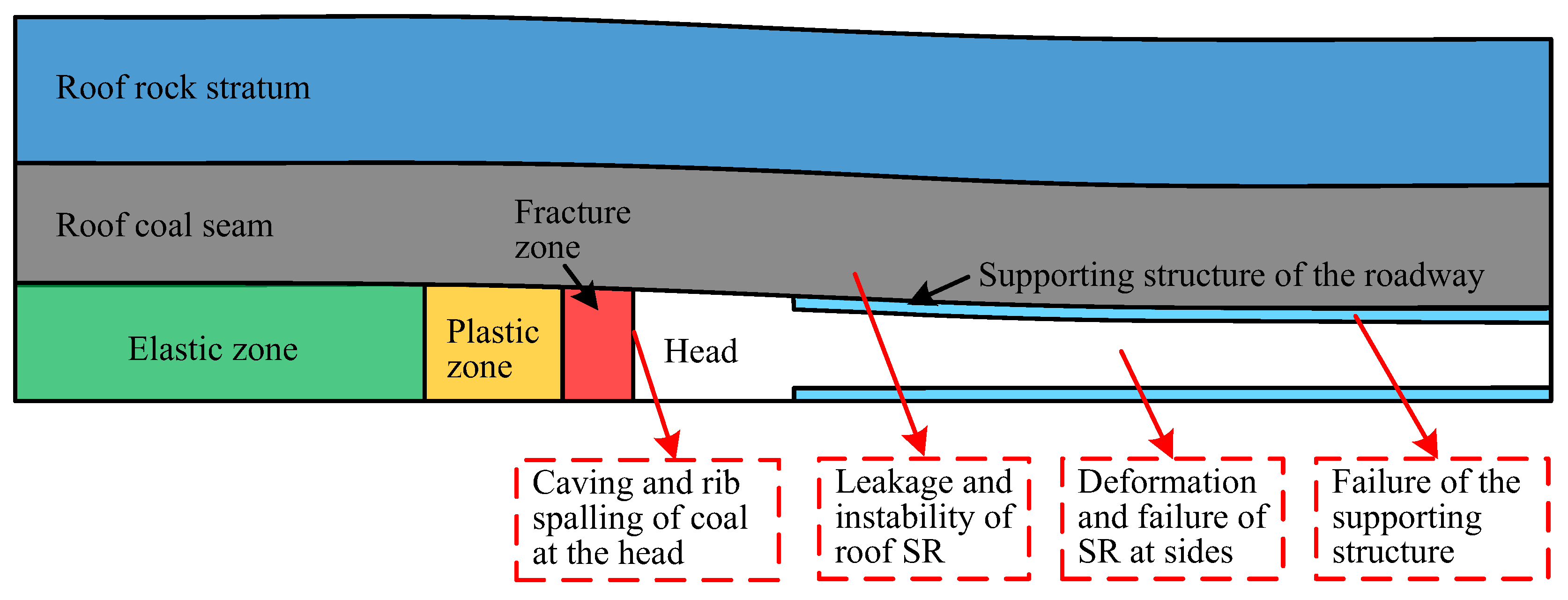
2.3. Cause Analysis on Roadway Instability

Through on-site investigation and laboratory tests, the causes of instability in the ESFFMCFR were preliminarily analyzed and summarized. According to Figure 4, the main causes of the deformation and failure are as follows:
(1)
The SR is of low strength. According to the strength tests on coal and rock mass, the 8# coal seam corresponds to a uniaxial compressive strength of about 2.23 MPa, with its tensile strength being around 0.45 MPa. Consequently, it breaks easily under high-stress conditions, which is unconducive to the stability of the FMCFR.
(2)
The bearing capacity of coal is not fully utilized. According to the previous deformation monitoring tests on the ESFFMCFR, the average vertical and horizontal convergence values are 729 mm and 547 mm, respectively, with the average variation rates being 19.8 mm/d and 17.9 mm/d, respectively. This suggests that the present ESFFMCFR can hardly utilize its own bearing capacity of SR.
(3)
The original support fails to seal the roadway surface, and the coal body at the head and on the roadway surface breaks and falls easily. Since the SR of the ESFFMCFR softens easily and is seriously fragmented, coal at the head and on the roadway surface often breaks and falls, affecting the normal roadway excavation and support, even causing roadway instability. As a result, the roadway needs to be repaired frequently.
(4)
The original support strength is insufficient. At present, the support of U-shaped steel sheds and anchor bolts is used for the ESFFMCFR. However, such support fails to maximize the bearing capacity of coal and cannot be applied to the ESFFMCFR in the long term. Moreover, it has the following defects: high roadway maintenance cost, great workload in repairment and proneness of roadway instability.

3. Synergistic Support System of “LDAGF”

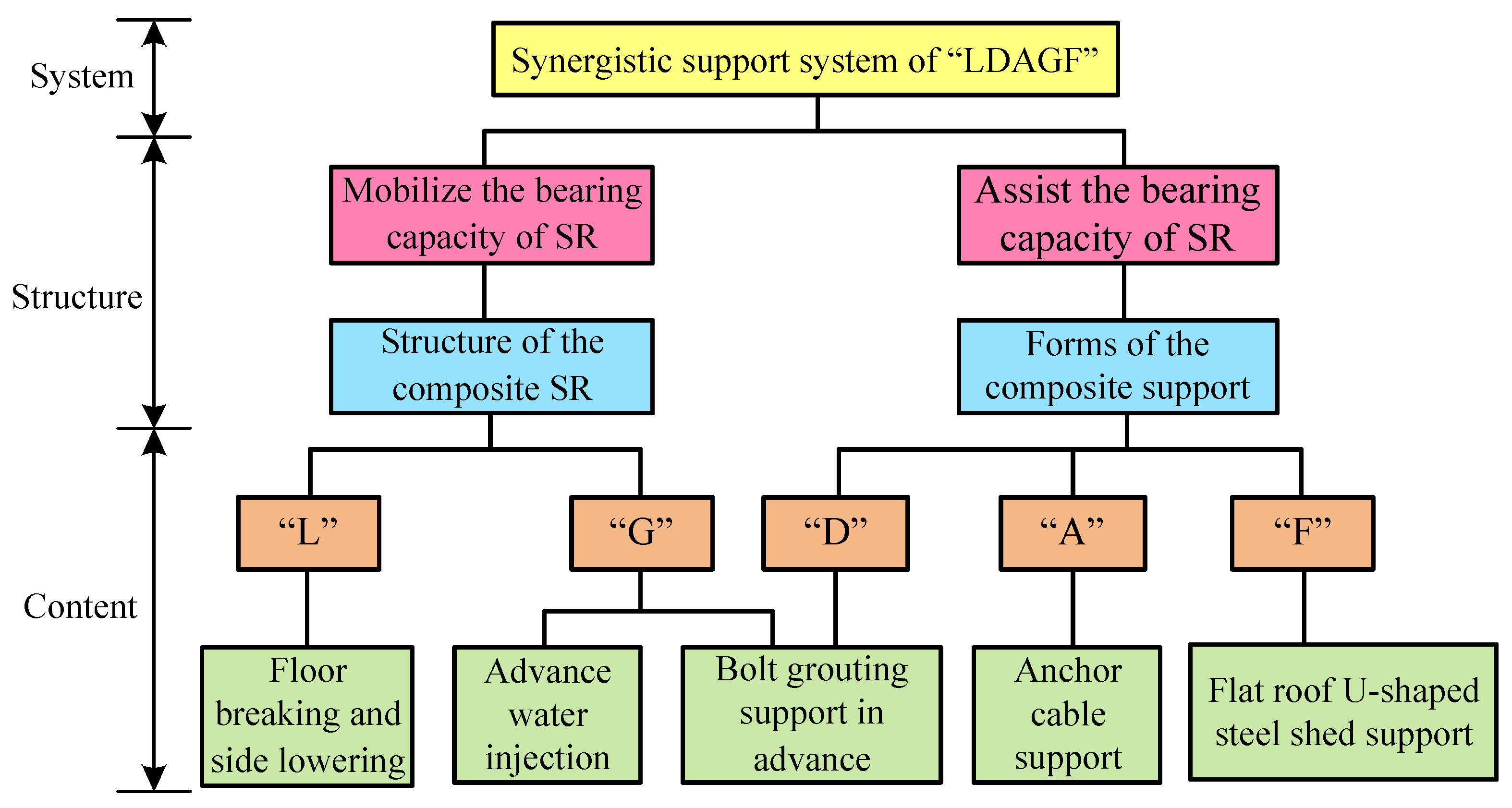
3.1. Principle of the Synergistic Support System

Synergy refers to the process or ability of multiple different resources or individuals to achieve a goal in a coordinated manner [23]. With respect to the safety of roadway SR in coal mines, a synergistic support aims to achieve the best control effect of SR stability at the minimum support cost. Therefore, based on the engineering response and support mechanism of roadway SR, and guided by the basic principle and methods of synergetics, the synergistic support of roadway SR in coal mines can explore the synergistic effect and evolution mechanism of a support–SR system in the stability control of roadway SR. In this process, the deformation control of roadway SR is the key. With the aid of a reasonable design and optimization of the support system, the interaction between roadway support and SR can be realized; the mechanical properties of the support and SR are fully utilized so that the overall support effect of the support system is superior to the sum of different support modes at the macro level, that is, the synergistic support effect of “1 + 1 > 2” is achieved, thereby avoiding the instability of roadway SR and the failure of the supporting structure. The basic function of a roadway support system is to maintain long-term stability of the roadway SR. In this system, roadway SR, as the main body of support, exists objectively. In terms of its function, the essence of roadway synergistic support is “mobilizing the bearing capacity of SR” and “assisting SR in playing the bearing role”. Apparently, SR is both the source and the major bearer of load, and its mechanical behaviors inevitably affect the stability of the whole system [24,25]. Therefore, maximizing the self-bearing capacity of SR is the basic principle of roadway support in coal mines. For an ESFFMCFR, “mobilizing the bearing capacity of SR” can be realized by improving the performance of shallow SR, hence giving full play to the bearing capacity of SR. “Assisting SR in playing the bearing role” requires assistance from the supporting structure; that is, a reliable control of SR stability can be realized through the joint action of the supporting structure and the SR.
On this basis, a synergistic support system of “LDAGF” was proposed considering the reasons for the roadway instability (Figure 5). This system can fundamentally solve the problems of serious deformation and failure, difficult support, long support time and slow excavation of the ESFFMCFR in thick seams. The technical measures adopted include floor breaking and side lowering of roadway, bolt advance support, anchor cable support, advance water injection and grouting and flat-roof U-shaped steel shed support. These measures improve the SR environment, fully utilize the deformation characteristics of SR and its own bearing capacity, and maintain the stability of the roadway. More specifically, these measures involve the following:
(1)
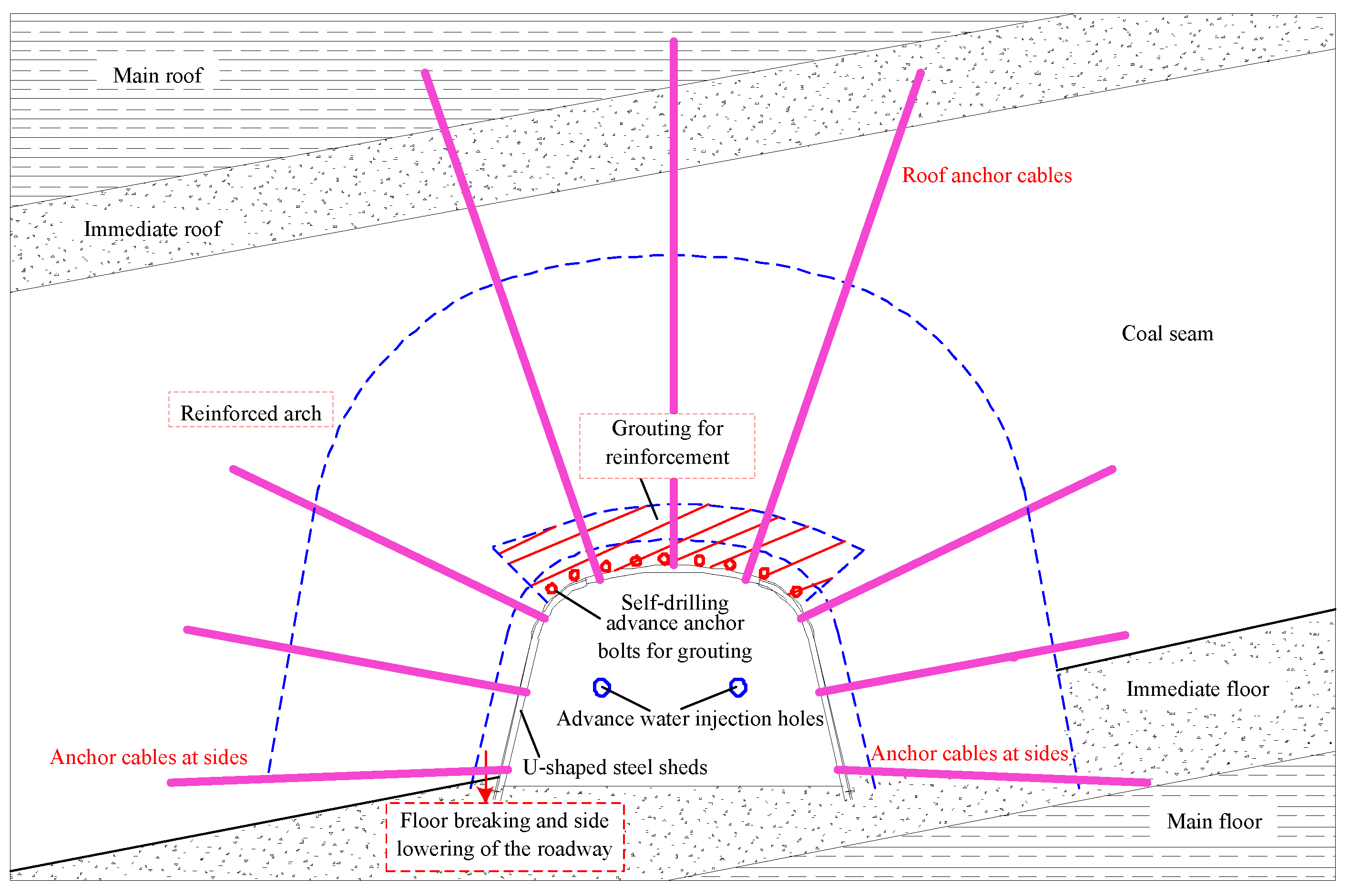
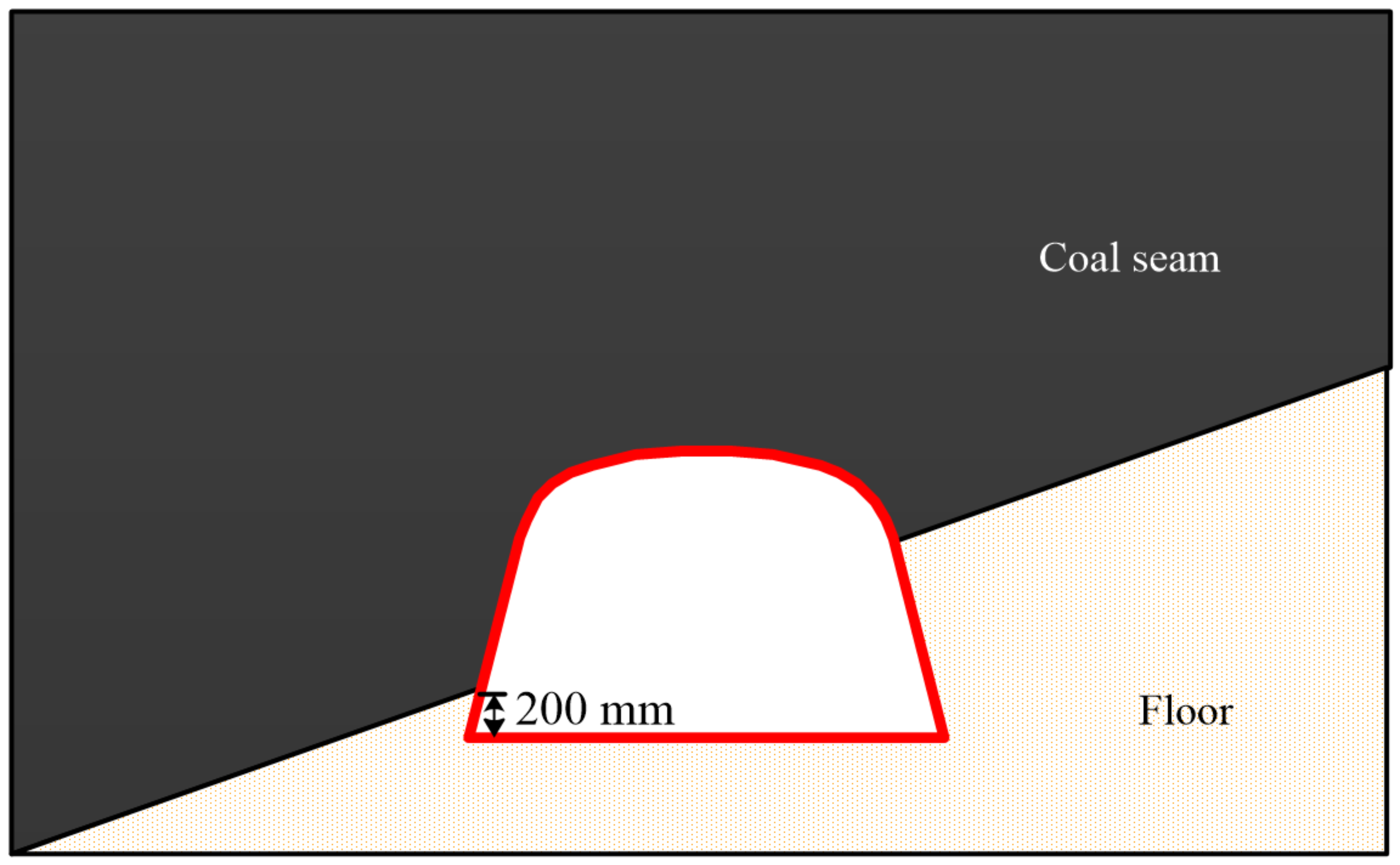
“L”—floor breaking and side lowering: According to the dip angle of the coal seam, reasonable floor breaking and side lowering is carried out to ensure that the shed legs at the two sides take root firmly and improve the lithologic strength at the roadway sides.
(2)
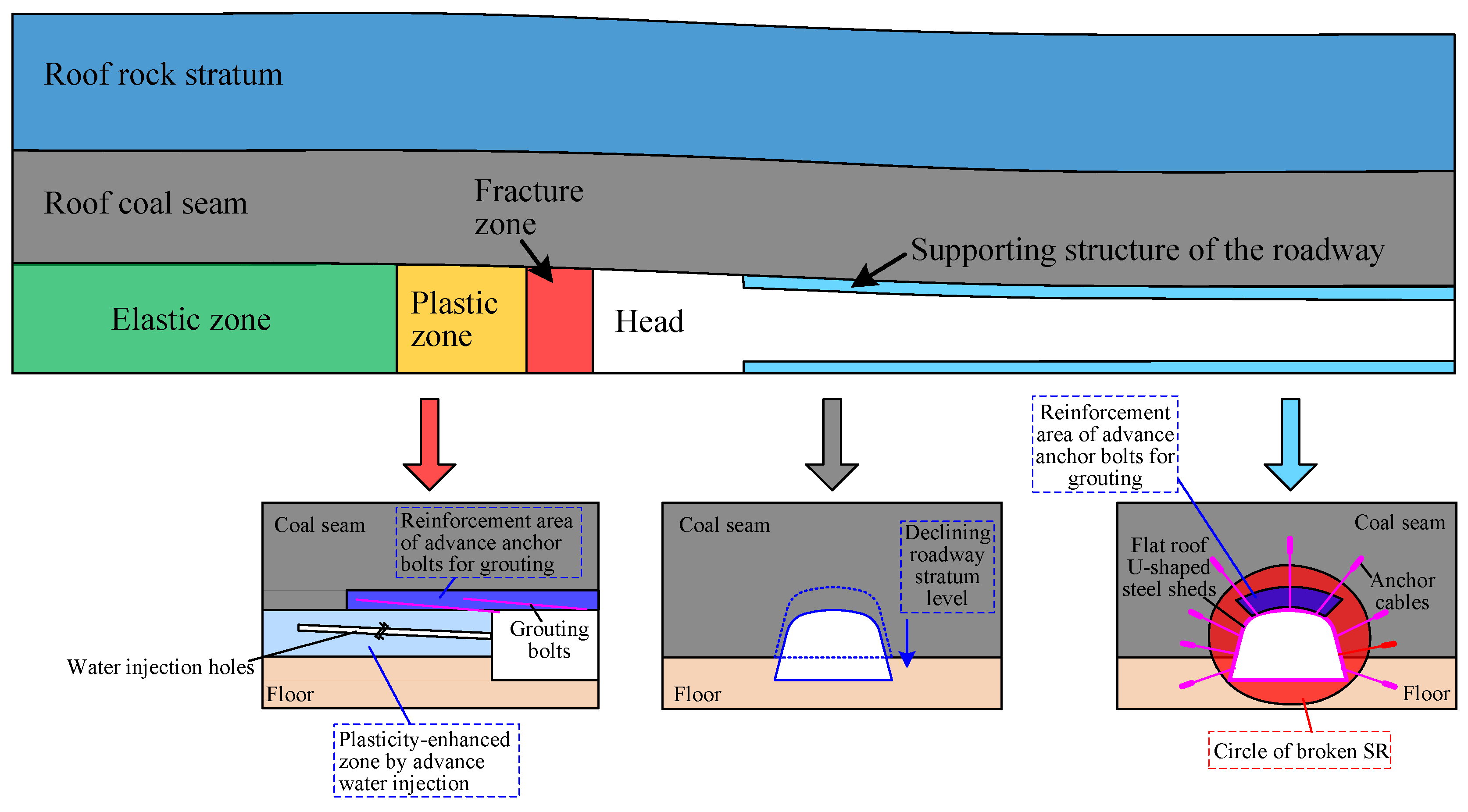
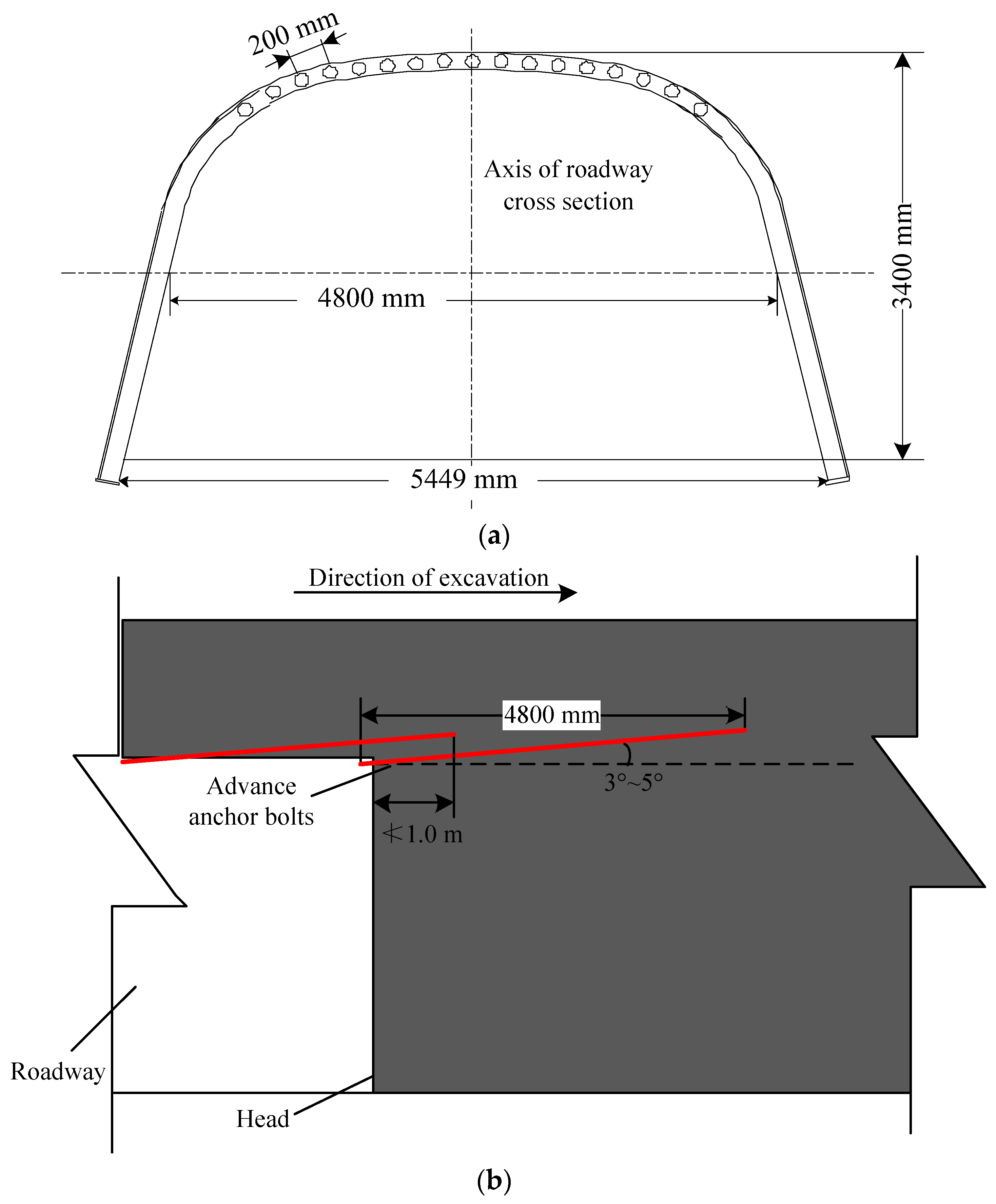
“D”—bolt advance support: Advance roof protection by self-drilling bolts for grouting is conducted along the roof of the shed beam. Then, the roof is grouted for solidification and the prevention of air leakage and roof caving.
(3)
“A”—anchor cable support: To improve the strength of the roadway support and enhance the stability of the flat-roof U-shaped steel shed support, anchor cables are used instead of bolts. The roof and sides are strengthened with long anchor cables and short cables, respectively.
(4)
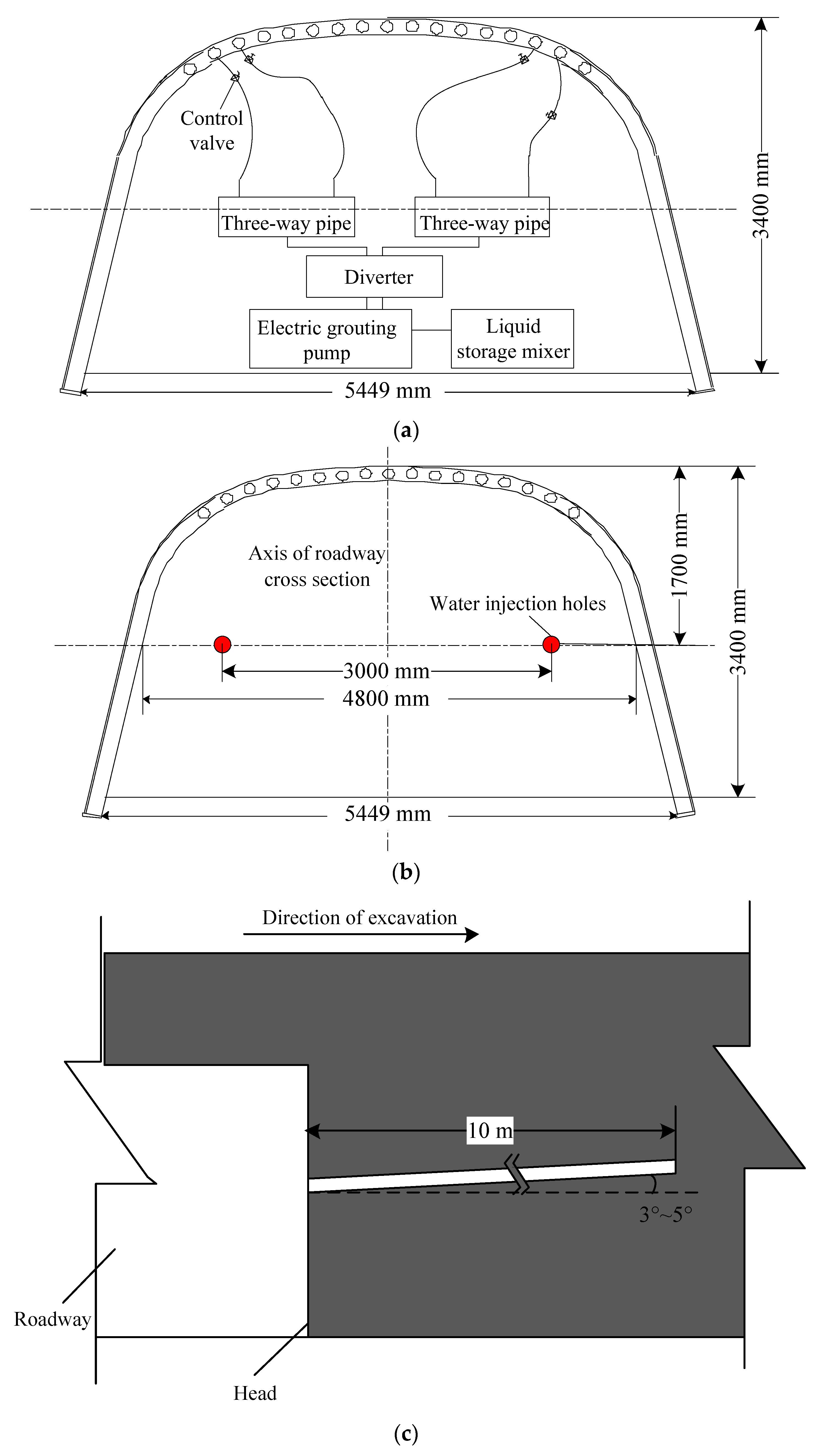
“G”—advance water injection and grouting: To enhance the plasticity of the coal body, the coal body at the head undergoes advance water injection while the roof is solidified by advance grouting before shed establishment with the aid of advance self-drilling bolts for grouting.
(5)
“F”—flat-roof U-shaped steel shed support: Flat-roof U-shaped steel sheds can provide high-strength rigid support because they boast good mechanical properties and high tensile and compressive strength. In addition, a flat roof is conducive to supporting the advance support of roadway during working face recovery, hence improving the recovery efficiency.

3.2. Characteristics of the Synergistic Support System of “LDAGF”

According to Figure 6, the synergistic support system is featured by the complementary advantages between the support forms (anchor cables, flat-roof U-shaped steel sheds and advance bolt grouting) and the SR improvement methods (floor breaking and side lowering and advance water injection for the coal body). The synergistic support system was applied to the ESFFMCFR in the LL, ZXZ, QD, GB, YY, TT, ZZ and XH coal mines in Huaibei mining area. Based on the effects of its support measures and the results of on-site industrial tests and mine pressure observation, the following three characteristics of the synergistic support system are summarized:
(1)
The bearing capacities of different support forms are complementary: Before roadway excavation, advance bolt grouting can effectively ensure the integrity of roadway roof SR with a simple construction process. The installation of flat-roof U-shaped steel sheds and anchor cables soon after roadway excavation not only provides large support resistance but also utilizes the anchor cables so that the SR deformation slowly acts on the steel sheds. Moreover, it can make up for the low resistance of conventional anchor mesh shotcrete support, and realize the complementarity of various support forms in bearing capacity, so as to achieve the best support effect.
(2)
The synergistic support system and the SR are integrated to play a bearing role: Before roadway excavation, advance water injection and grouting can enhance the plasticity of the coal body while advance grouting can solidify the roof and improve the integrity of the roadway and the head. Compared with anchor bolts, anchor cables can anchor into deep and stable rock strata, transfer the additional load from the shallow SR to the deep SR and make the SR a three-way compression-bearing body by applying a large preload. On this basis, anchor cables are adopted to fix the flat-roof U-shaped steel sheds. Hence, the synergistic support system can realize an omni-directional overall bearing of deep and shallow SR both before and after excavation.
(3)
The one-time permanent support of SR is realized: It can avoid repeated renovation of roadways and realize one-time permanent support. Underground monitoring reveals that the ESFFMCFR supported by the synergistic support system can fully mobilize the bearing capacity of SR and realize ventilation and transportation for a long time without regular renovation, thus saving the roadway support cost to a certain extent and yielding remarkable economic benefits.

4. Engineering Application

4.1. Design for the Construction of the Synergistic Support System of “LDAGF”

According to the synergistic support system, its construction process in the ESFFMCFR is as follows: “L”—floor breaking and side lowering→“D”—bolt advance support→“G”—advance water injection and grouting→“F”—flat-roof U-shaped steel shed support→“A”—anchor cable support. First, according to the dip angle of the coal seam in the extremely soft and fragile fully mechanized caving face, the floor breaking and side lowering begins. After the roadway positions are determined, self-drilling screw steel bolts for grouting are arranged along the roof of the shed beam for advance roof protection. Afterwards, the bolts undergo advance grouting to solidify the roof. Meanwhile, advance water injection is performed on the coal at the head to enhance the coal’s plasticity. After the advance support is completed, during slurry solidification, the flat-roof U-shaped steel sheds are used to support the ESFFMCFR in thick seams. Then, the roadway roof, sides and flat-roof U-shaped steel shed legs are reinforced by anchor cables to enhance stability.
The synergistic support system of “LDAGF” for the ESFFMCFR in thick seams is shown in Figure 7. Its specific design is as follows:
(1)
“L”—floor breaking and side lowering
According to the dip angle of the coal seam, the floor breaking and side lowering construction is performed. The lower side is lowered by 200 mm so that most of the higher side is located in the floor strata of the coal seam, hence improving the SR environment of the roadway sides. Meanwhile, floor breaking and side lowering into the floor strata can ensure that the flat-roof U-shaped steel shed legs at the two sides take root firmly and improve the lithologic strength of the roadway sides (Figure 8).
(2)
“D”—bolt advance support
The advance support of the ESFFMCFR is achieved by self-drilling screw steel bolts for grouting, which are arranged according to the section contours. The bolt spacing is about 200 mm (the spacing can be adjusted according to the distance between the coal seam and gangue). The bolts are arranged at a 3–5° angle with the roadway construction slope to ensure that the bolts are on the same plane. The anchor bolts are 4800 mm long, but the overlapping length of each group of bolts is ≮1.0 m. Over-excavation is prohibited (the circulating footage distance is controlled according to the length of the anchor bolts and overlapping distance). The layout of the advance self-drilling screw steel anchor bolts for grouting is shown in Figure 9.
(3)
“G”—advance water injection and grouting in the roadway
An electric grouting pump is adopted. Then, 3–5 advance self-drilling screw steel anchor bolts can be grouted at the same time by installing a diverter at the outlet hole of the electric grouting pump. When the grouting pressure meets the requirement, the grouting pipeline is closed; the holes are changed to continue grouting. The layout of the grouting pipeline is shown in Figure 10a.
To enhance the coal’s plasticity, the coal body at the head is injected with water in advance. According to previous experience and the results of numerical simulation optimization, two holes are injected with water in each cycle. The other parameters are as follows: the hole spacing is 3 m (arranged separately according to the axis of roadway cross section), the holes are about 1.7 m away from the roof and the drilling depth is 10 m with an elevation angle of 3–5° with the roadway direction. The holes are sealed with hole-sealers, and the water injection pressure is 0.5 MPa. The arrangement of the water injection holes is based on the infiltration range of water in the coal body. The water injection holes are arranged according to Figure 10b,c.
(4)
“F”—flat-roof U-shaped steel shed support in the roadway
The flat roof U-shaped steel shed support adopts 36U-shaped steel retractable three-core arch supports, each with three sections (one for the roof beam and two for the U-legs). The overlapping part is fixed with three pairs of limit cables; the overlapping length is 500 mm, the nut tightening force is ≮300 N·m, the shed spacing is 700 m and the leg socket depth is 200 mm. The flat-roof U-shaped steel sheds are arranged according to Figure 11.
(5)
“A”—anchor cable support in the roadway
The roof anchor cables are arranged in the “333” mode; the specifications are as follows: YMSΦ21.8/6200 mm (8.2 m and 10 m for standby); row spacing 1200 × 700 mm. The middle roof and anchor cables at the right side are equipped with anchor plates; the anchor cables at the left side are equipped with lock beams (one beam and one cable for two sheds), which are arranged at intervals. Since anchor cables that are 8200 mm and 10,000 mm long are provided on-site, the cables can be adjusted according to the variation in coal thickness to ensure that the anchor cables take root in the hard roof with a depth of ≮1.5 m.
The sides adopt YMSΦ21.8/4100 mm anchor cables for support with a row spacing of 1200 × 700 mm. They are arranged 300 mm and 1500 mm away from the floor, respectively. The anchor cables are arranged in the “323” mode. When the anchor cables are 1500 mm from the floor, shoulder anchor cables are used with trays. When they are 300 mm away from the floor, they are used with lock beams (one beam and two cables for four sheds). The lock beams closely follow the front probe beam; three rolls of resin anchoring agent are used for each anchor cable. Resin anchoring agents MSZ-2950 and MSZ-2550 are employed for the rock mass and coal body, respectively. The preload of the rock mass is ≮100 kN (29 MPa); that of the coal body is ≮60 kN (17.4 MPa). The layout of the anchor cable support is shown in Figure 11.

4.2. Support Test of the FMCFR in the 8# Coal Seam of XH Coal Mine

After the excavation of the 815 working face transportation roadway in the 8# coal seam of XH Coal Mine, industrial tests were carried out to apply the synergistic support system of “LDAGF” on a 300 m long section of ESFFMCFR. Monitoring devices were installed during the industrial tests to collect data. The on-site test adopted an anchor rod dynamometer and a tunnel surface convergence instrument. Then, the support effect for the 815 working face transportation roadway was evaluated and analyzed.
(1)
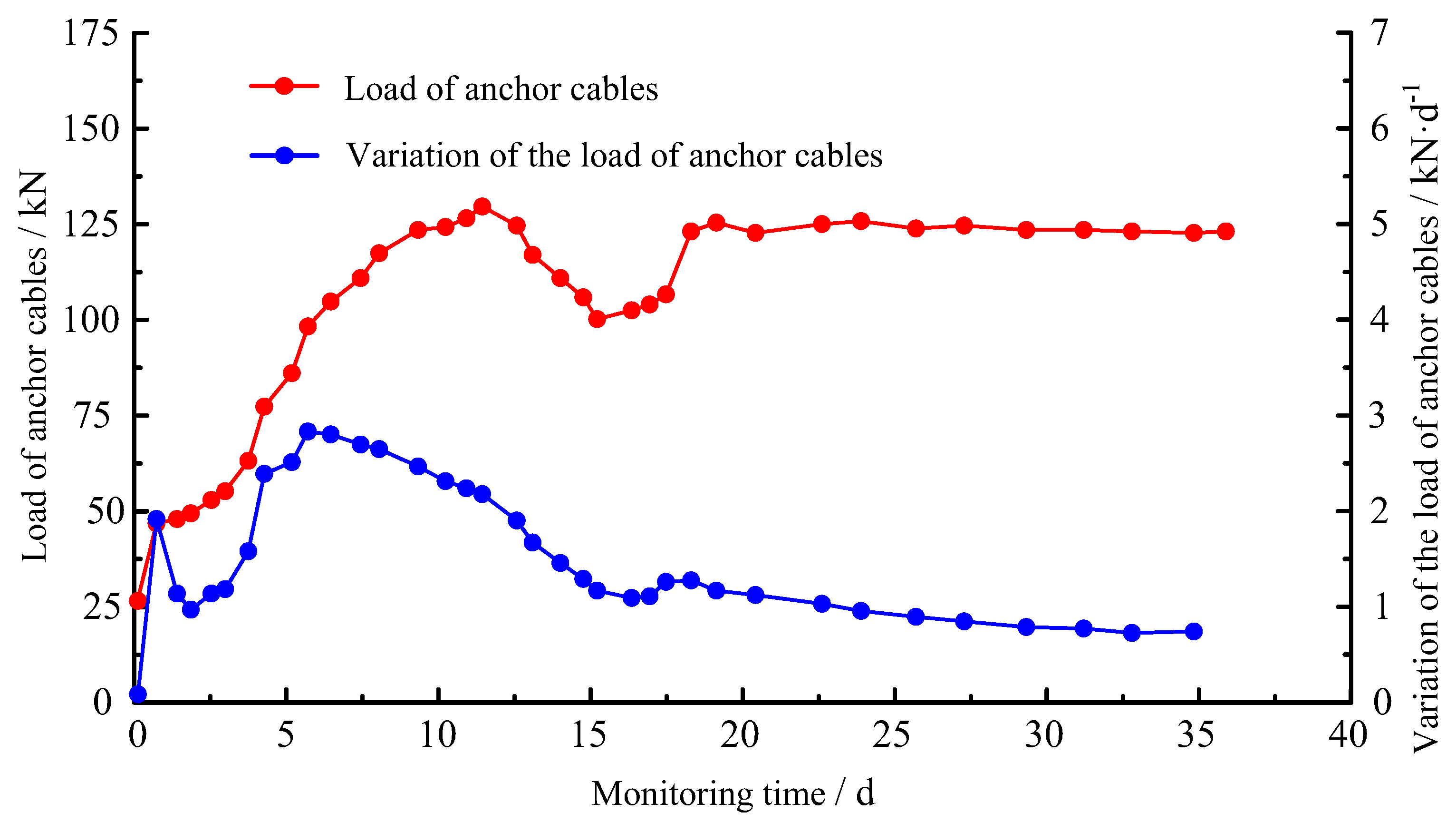
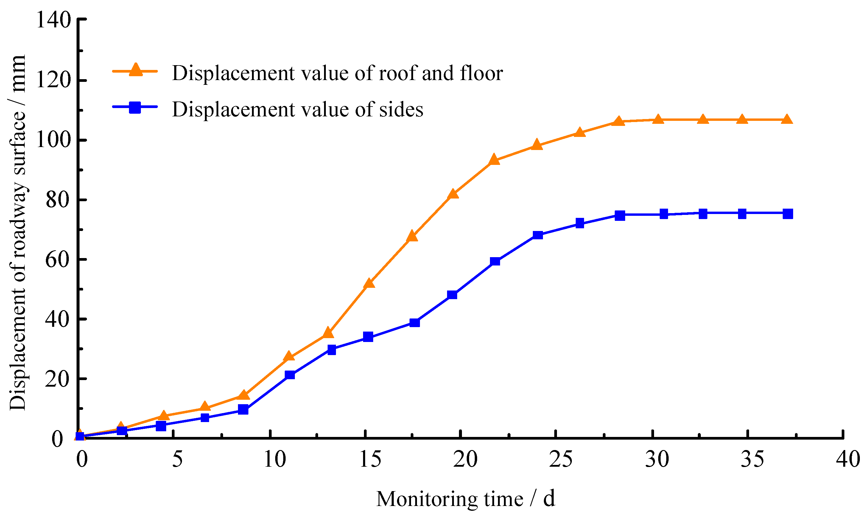
Analysis of the Monitored Data on the Mine Pressure
Monitored data on the mine pressure of the transportation roadway in XH Coal Mine mainly include the stress of anchor cables and the displacement of the roadway surface.
The stress of cables was monitored by an online cable hydraulic pillow. The stress variation in the cables monitored by the pillow after the application of the synergistic support system is shown in Figure 12. In the monitoring period, roadway mining disturbance occurs, so the stress of the anchor cables decreases to a certain extent and then rises. Overall, the stress of the anchor cables gradually rises and then stabilizes, reaching its maximum value of 135 kN. This indicates that the anchor cables in the synergistic support system of “LDAGF” can mobilize the bearing capacity of SR well and lead to stable stress on the cables.
The displacement curves of the roof, floor and two sides of the 815 working face transportation roadway in XH Coal Mine are shown in Figure 13. During the monitoring period, the deformation of roadway SR varies significantly within 25 days after excavation, and tends to stabilize on the 35th day. Before the roadway stabilizes, the displacement value of the roof and floor is 117 mm, with the average displacement speed being 3.34 mm/d. These two parameters of the two sides are 66 mm and 1.89 mm/d, respectively. During the whole monitoring period, the synergistic support system can greatly mobilize the bearing capacity of the SR and effectively control SR deformation.
(2)
Evaluation on the Support Effect
According to the above data, the synergistic support system of “LDAGF” can effectively control the serious deformation of the ESFFMCFR. Moreover, the synergistic action of different supporting structures can lead to appropriate stress on the anchor cables and realize the expected effect. The synergistic support system can fully mobilize the overall bearing capacity of the SR and effectively resist roadway deformation.

4.3. Support Test on the FMCFR in the 8# Coal Seam of GB Coal Mine

After the excavation of the 842 air roadway (the 84 mining area, the 8# coal seam, GB Coal Mine), industrial tests were performed to apply the synergistic support system on a 500 m long section of ESFFMCFR. During the industrial tests, monitoring devices were installed to collect data. Subsequently, the support effect of the 842 air roadway was evaluated and analyzed.
(1)
Analysis on the Monitored Data of the Mine Pressure
Mainly roadway surface displacement data were monitored for the mine pressure of the 842 air roadway in GB Coal Mine. The displacement variations in the roof, floor and two sides of the 842 air roadway in GB Coal Mine are presented in Figure 14. During the monitoring period, the deformation of roadway SR varies notably within 25 days after excavation, yet tends to stabilize on the 30th day. Before the roadway stabilizes, the displacement value of roof and floor is 121 mm, with its average displacement speed being 4.03 mm/d; those two parameters of the two sides are 74 mm and 2.47 mm/d, respectively. In the whole monitoring period, the deformation of SR in ESFFMCFR can be effectively controlled through the synergistic support system of “LDAGF”.
(2)
Evaluation on the Support Effect
The supporting structures boast complementary advantages. Hence, the bearing capacity of the synergistic support system can effectively resist the severe deformation of the SR and fully mobilize its bearing capacity. Nevertheless, both the roof and floor anchor cables of the roadway can realize the expected effect and achieve the one-time permanent support of the roadway.

5. Conclusions

(1)
The roof and two sides consist of extremely soft and fragile coal bodies. Therefore, in the SR of the FMCFR, fractures are developed and the support requires a high capacity. Conventional support systems can hardly control SR deformation. The extremely soft and fragile SR in the FMCFR and the mutual independence between the support and the SR are the primary reasons for the roadway instability.
(2)
This study is based on the synergistic mechanism of support and SR as well as the basic principles of synergetics. By enhancing the properties of roadway SR, improving the SR environment and promoting the support strength, the roadway can achieve an omni-directional overall bearing of deep and shallow SR both before and after excavation. Meanwhile, the generation and development of micro-cracks in the head and roadway SR are inhibited, and the spatially mutual support of the roadway and SR is enhanced. Finally, a synergistic support system of “LDAGF” for the ESFFMCFR is proposed.
(3)
On-site applications have shown that the synergistic support system for the ESFFMCFR can overcome the defects of a loose supporting structure and serious SR deformation in conventional support, improve the distribution law of stress of the head and plastic zone in the ESFFMCFR, effectively prevent the development of tangential fractures, and considerably improve the integrity and bearing capacity of roadway SR. This synergistic support system boasts an excellent roadway support effect and is of great guiding significance for similar roadways.

Author Contributions

Conceptualization, X.N.; Software, Y.Y.; Validation, X.H.; Writing—original draft, X.N.; Writing—review & editing, K.D. and Y.Y. All authors have read and agreed to the published version of the manuscript.

Funding

This research was funded by the Anhui Provincial Outstanding and Topnotch Talent Cultivational Program [Grant No. gxyq2022067]. And The APC was funded by Carbon Issues Research Center in Huainan Normal University.

Institutional Review Board Statement

Not applicable.

Informed Consent Statement

Not applicable.

Data Availability Statement

The data used to support the findings of this study are included within the article.

Conflicts of Interest

Author Xianjie Ni was employed by the company China Coal Xinji Energy Limited Liability Company. The remaining authors declare that the research was conducted in the absence of any commercial or financial relationships that could be construed as a potential conflict of interest.

References

  1. Wang, H.; Jiang, C.; Zheng, P.; Li, N.; Zhan, Y. Deformation and Failure Mechanism of Surrounding Rocks in Crossed–roadway and Its Support Strategy. Eng. Fail. Anal. 2020, 116, 104743. [Google Scholar] [CrossRef]
  2. Li, Q.; Shi, W.; Yang, R. Deformation Mechanisms in a Coal Mine Roadway in Extremely Swelling Soft Rock. Springerplus 2016, 5, 1310. [Google Scholar] [CrossRef]
  3. Jing, H.; Wu, J.; Yin, Q.; Wang, K. Deformation and Failure Characteristics of Anchorage Structure of Surrounding Rock in Deep Roadway. Int. J. Min. Sci. Technol. 2020, 30, 593–604. [Google Scholar] [CrossRef]
  4. Chen, D.; Zhang, Q.; Xie, S.; Jiang, Z.; Li, Y.; Gao, M.; Li, H.; Wu, X.; Wang, E.; Shi, S.; et al. Combined Support Technology for Main Roadway Passing Through Goaf: A Case Study. Energy Sci. Eng. 2020, 8, 3925–3941. [Google Scholar] [CrossRef]
  5. An, Y.; Zhang, N.; Zhao, Y.; Xie, Z. Field and Numerical Investigation on Roof Failure and Fracture Control of Thick Coal Seam Roadway. Eng. Fail. Anal. 2021, 128, 105594. [Google Scholar] [CrossRef]
  6. Xu, X.; He, F.; Li, X.; He, W. Research on Mechanism and Control of Asymmetric Deformation of Gob Side Coal Roadway with Fully Mechanized Caving Mining. Eng. Fail. Anal. 2021, 120, 105097. [Google Scholar] [CrossRef]
  7. Wang, W.; Pan, Y.; Xiao, Y. Synergistic Mechanism and Technology of Cable Bolt Resin Anchoring for Roadway Roofs with Weak Interlayers. Rock Mech. Rock Eng. 2022, 55, 3451–3472. [Google Scholar] [CrossRef]
  8. Wang, T.; Chang, J.; Yin, Z.; Gong, P.; Shi, W.; Li, N. Theory and Full-scale Simulation Testing of the Mechanical Properties of Anchors Under a Variable Lateral Pressure Coefficient. Arab. J. Geosci. 2021, 14, 1–9. [Google Scholar] [CrossRef]
  9. Ma, S.; Liu, X.; Gutierrez, M. Critical Issues for the Ground Control of Shallow Roadways in Weak Ground: A Case Study. Arab. J. Geosci. 2020, 13, 623. [Google Scholar] [CrossRef]
  10. Cao, J.; Zhang, N.; Wang, S.; Wei, Q. Investigation of Mechanical Properties for Group Anchors. Appl. Sci. 2021, 11, 1521. [Google Scholar] [CrossRef]
  11. Yan, H.; Zhang, J.X.; Ding, Z.W.; Huang, Y.L. Surrounding Rock Deformation Mechanism of Roadways with Extra-thick Coal Seam. Disaster Adv. 2014, 6, 226–233. [Google Scholar]
  12. Jiao, Y.Y.; Song, L.; Wang, X.Z.; Adoko, A.C. Improvement of the U-shaped Steel Sets for Supporting the Roadways in Loose Thick Coal Seam. Int. J. Rock Mech. Min. Sci. 2013, 60, 19–25. [Google Scholar] [CrossRef]
  13. Ma, Z.; Liang, X.; Fu, G.; Zou, Y.; Chen, A.; Guan, R. Experimental and Numerical Investigation of Energy Dissipation of Roadways with Thick Soft Roofs in Underground Coal Mines. Energy Sci. Eng. 2021, 9, 434–446. [Google Scholar] [CrossRef]
  14. Xie, S.; Wu, X.; Chen, D.; Sun, Y.; Wang, E.; Wu, X.; Duan, X.; Jiang, Z.; Qi, P.; Shi, S. Failure Mechanism and Control Technology of Thick and Soft Coal Fully Mechanized Caving Roadway under Double Gobs in Close Coal Seams. Shock Vib. 2020, 2020, 8846014. [Google Scholar] [CrossRef]
  15. Yang, D.W.; Ma, Z.G.; Qi, F.Z.; Gong, P.; Liu, D.P.; Zhao, G.Z.; Zhang, R.R. Optimization Study on Roof Break Direction of Gob-side Entry Retaining by Roof Break and Filling in Thick-layer Soft Rock Layer. Geomech. Eng. 2017, 13, 195–215. [Google Scholar]
  16. Gu, S.; Jiang, B.; Wang, G.; Dai, H.; Zhang, M. Occurrence Mechanism of Roof-Fall Accidents in Large-Section Coal Seam Roadways and Related Support Design for Bayangaole Coal Mine, China. Adv. Civ. Eng. 2018, 2018, 6831731. [Google Scholar] [CrossRef]
  17. Zhan, Q.; Zheng, X.; Du, J.; Xiao, T. Coupling Instability Mechanism and Joint Control Technology of Soft-Rock Roadway with a Buried Depth of 1336 m. Rock Mech. Rock Eng. 2020, 53, 2233–2248. [Google Scholar] [CrossRef]
  18. Yang, X.; Wang, E.; Wang, Y.; Gao, Y.; Wang, P. A Study of the Large Deformation Mechanism and Control Techniques for Deep Soft Rock Roadways. Sustainability 2018, 10, 1100. [Google Scholar] [CrossRef]
  19. Wu, Y.B.; Hu, J.H.; Zhang, X.Y.; Qin, Y.G.; Zhang, Z.B.; Zhao, X.C. Study on Bearing Capacity Characteristics of Steel Structure Support in Soft Rock Roadway. Energy Sci. Eng. 2021, 9, 2423–2433. [Google Scholar] [CrossRef]
  20. Li, G.; Ma, F.; Guo, J.; Zhao, H.; Liu, G. Study on Deformation Failure Mechanism and Support Technology of Deep Soft Rock Roadway. Eng. Geol. 2020, 264, 105262. [Google Scholar] [CrossRef]
  21. Wang, H.; Zheng, P.Q.; Zhao, W.J.; Tian, H.M. Application of A Combined Supporting Technology with U-shaped Steel Support and Anchor-grouting to Surrounding Soft Rock Reinforcement in Roadway. J. Cent. South Univ. 2018, 25, 1240–1250. [Google Scholar] [CrossRef]
  22. Wu, A.; Chen, S.; Wang, Y.; Chen, X. Failure Mechanism and Supporting Measures for Large Deformation of Soft Rock Roadway in Baluba Copper Mine. Arch. Min. Sci. 2018, 63, 449–464. [Google Scholar] [CrossRef] [PubMed]
  23. Yu, K.; Ren, F.; Puscasu, R.; Lin, P.; Meng, Q. Optimization of Combined Support in Soft-rock Roadway. Tunn. Undergr. Space Technol. 2020, 103, 103502. [Google Scholar] [CrossRef]
  24. Zhao, C.; Li, Y.; Liu, G.; Meng, X. Mechanism Analysis and Control Technology of Surrounding Rock Failure in Deep Soft Rock Roadway. Eng. Fail. Anal. 2020, 115, 104611. [Google Scholar] [CrossRef]
  25. Skrzypkowski, K.; Zagórski, K.; Zagórska, A.; Apel, D.B.; Wang, J.; Xu, H.; Guo, L. Choice of the Arch Yielding Support for the Preparatory Roadway Located near the Fault. Energies 2022, 15, 3774. [Google Scholar] [CrossRef]
Figure 1. Deformation of SR in the ESFFMCFR.
Applsci 14 08485 g001
Figure 2. X-ray diffraction spectrum of the coal seam in the ESFFMCFR.
Applsci 14 08485 g002
Figure 3. Mechanical experiments of coal and rock mass. (a) Uniaxial compression test (after experiment). (b) Shear test (after experiment). (c) Brazilian splitting test (after experiment).
Applsci 14 08485 g003
Figure 4. Structure diagram of SR in the ESFFMCFR.
Applsci 14 08485 g004
Figure 5. Basic components of the synergistic support system of “LDAGF”.
Applsci 14 08485 g005
Figure 6. Schematic diagram of the synergistic support system of “LDAGF”.
Applsci 14 08485 g006
Figure 7. Synergistic support system of “LDAGF”.
Applsci 14 08485 g007
Figure 8. Schematic diagram of floor breaking and side lowering of the roadway.
Applsci 14 08485 g008
Figure 9. Layout of advance bolts in the roadway. (a) Roadway section. (b) Roadway cross section.
Applsci 14 08485 g009
Figure 10. Layout of advance water injection and grouting in the roadway. (a) Layout of roadway advance grouting. (b) Section of the layout of advance water injection. (c) Cross section of the layout for the advance water injection.
Applsci 14 08485 g010
Figure 11. Schematic diagram of flat-roof U-shaped steel sheds and anchor cables for the roadway support. (a) Roadway section. (b) Roadway plan.
Applsci 14 08485 g011
Figure 12. Curve of force on and variation in anchor cables over time.
Applsci 14 08485 g012
Figure 13. Displacement curves of roof, floor and two sides of the 815 transport roadway in XH Coal Mine.
Applsci 14 08485 g013
Figure 14. Displacement values of roof, floor and two sides of the 842 air roadway in GB Coal Mine.
Applsci 14 08485 g014
Table 1. Mineral compositions.
Molecular FormulaCO3 (Substrate)SiO2Al2O3CaOSOthers
Content74.7%12.04%9.47%0.961%0.676%2.153%
Table 2. Physical and mechanical parameters of different rocks.
SamplePoisson’s RatioCompressive Strength/MPaTensile Strength/MPaCohesion/MPaInternal Friction Angle/°Elastic Modulus/GPa
Average value of the 8# coal seam0.3192.230.450.21222.02
Average value of roof mudstone0.26622.422.062.002822.14
Average value of floor mudstone0.26717.291.301.943022.35
Disclaimer/Publisher’s Note: The statements, opinions and data contained in all publications are solely those of the individual author(s) and contributor(s) and not of MDPI and/or the editor(s). MDPI and/or the editor(s) disclaim responsibility for any injury to people or property resulting from any ideas, methods, instructions or products referred to in the content.

