Abstract
This paper presents initial findings from aeroelastic studies conducted on a wing-propeller model, aimed at evaluating the impact of aerodynamic interactions on wing flutter mechanisms and overall aeroelastic performance. The flutter onset is assessed using a frequency-domain method. Mid-fidelity tools based on the time-domain approach are then exploited to account for the complex aerodynamic interaction between the propeller and the wing. Specifically, the open-source software DUST and MBDyn are leveraged for this purpose. The investigation covers both windmilling and thrusting conditions. During the trim process, adjustments to the collective pitch of the blades are made to ensure consistency across operational points. Time histories are then analyzed to pinpoint flutter onset, and corresponding frequencies and damping ratios are identified. The results reveal a marginal destabilizing effect of aerodynamic interaction on flutter speed, approximately 5%. Notably, the thrusting condition demonstrates a greater destabilizing influence compared to the windmilling case. These comprehensive findings enhance the understanding of the aerodynamic behavior of such systems and offer valuable insights for early design predictions and the development of streamlined models for future endeavors.
1. Introduction
Electrification in urban air mobility is crucial for creating sustainable, quieter, and more efficient transportation systems that will revolutionize the way we navigate our cities, reducing carbon footprints and enhancing urban life. Next-generation aircraft configurations can benefit from electric propulsion in terms of aerodynamic efficiency and simplicity [1,2], leading to the development of distributed electric propulsion systems (DEPs), where the propulsion can be placed at multiple locations. The relatively lightweight electric propulsion allows for propellers to be distributed along the wingspan, taking advantage of their high efficiency at low speeds [3]. However, these mass-optimized structures are inherently flexible. Combined with the presence of rotating propellers, the dynamic behavior becomes a critical factor, particularly for aeroelastic aspects. In the context of DEP configuration, the main aeroelastic phenomena are wing flutter and propeller whirl flutter. While wing flutter is a well-examined phenomenon, whirl flutter is receiving renewed attention due to novel configurations.
Whirl flutter was discovered on the Lockheed L-188C Electra, after two fatal accidents in 1959 and 1960 [4]. The phenomenon may occur in flexible-mounted wing-propeller systems and requires one to consider the influence of rotating masses producing centrifugal, Coriolis, and gyroscopic forces/moments in addition to aerodynamic loads. The instability is driven by a whirl motion that can destabilize the pitch or yaw degree of freedom of the wing–pylon elastic suspension of the propeller. The foundational focus and development of suitable estimation procedures emerged in the 1960s [5,6]. A straightforward structural model by Reed and Bland was developed during this period, and the associated aerodynamics were described analytically [5]. This work laid the groundwork for whirl flutter theory.
The aeroelastic constraints for next-generation aircraft designs pose a critical challenge for engineers. Indeed, a thorough understanding of the aeroelastic behavior of novel aircraft configurations is essential, followed by the development of reliable aeroelastic prediction methods. Gaining a detailed understanding of the aeroelastic behavior requires examining the complex interactions between the wings and propellers, taking into account factors like propeller mounting stiffness, wing dynamics, propeller performance, and aerodynamic interactions. It is therefore not surprising that extensive research has been conducted recently on aeroelastic instabilities concerning wing flutter and propeller whirl flutter. An enhanced method for unsteady propeller aerodynamics used for whirl flutter was presented in [7] and compared to low- and mid-fidelity methods in [8]. The stabilizing effect of the propeller aerodynamic torque on whirl flutter was investigated in [9].
For coupled wing-propeller models, structural interactions between the wing and propeller were studied by Bennet and Bland with an analytical approach validated by experimental results in [10] and recently investigated by the authors [11] using both frequency and nonlinear time-domain simulation tools, providing guidelines for the aeroelastic design of next-generation eVTOL aircraft. The influence of gyroscopic effects on aeroelastic stability of wing-propeller systems was highlighted in [12]. Concerning aerodynamic interaction, it is well known that aircraft designs with a DEP have a beneficial impact on the lift–drag ratio and overall aircraft performance [1,2]. However, several questions remain unanswered. For instance, the effect of aerodynamic interaction between propellers and the wing on aeroelastic behavior is still under investigation. Preliminary studies indicate that both the thrust generated by propellers [13,14] and the aerodynamic effects of propellers on the flow around the wing [15,16] influence the aeroelastic stability. Recently, the aerodynamic interaction was discovered to be slightly destabilizing for whirl flutter cases [17].
The present study aims to enhance the understanding of the flutter mechanism in wing-propeller models, investigating the influence of aerodynamic interference between the propeller and the wing. To make this happen, the pylon mounting stiffness of the wing-propeller system presented in this work is modified to induce wing flutter. Aerodynamic interference effects between the wing and the propeller are captured using a vortex-particle method (VPM). Aeroelastic analyses are performed by coupling the VPM with a multibody dynamics tool, which takes into account the nonlinear dynamics of the interconnected rigid and flexible bodies representing the aircraft components.
The paper proceeds as follows: the first section outlines the methodology and the numerical tools used for the aeroelastic analyses. Subsequently, the dynamic model setup of the wing-propeller system is presented, along with the initial validation of the two sub-components. Stability results are then presented and discussed, comparing the flutter diagrams of the wing-propeller system with and without the aerodynamic interference effects. Finally, a section of concluding remarks ends the paper.
2. Numerical Tools
In the present work, aeroelastic stability analyses are performed using both linear frequency-domain and nonlinear time-domain simulation environments.
The frequency-domain simulations are conducted using an in-house toolbox (SDBox). This tool offers robust capabilities for efficient analysis, providing key insights into flutter points, natural frequencies, damping ratios, and mode shapes from the initial results. SDBox was developed in MATLAB (R2022b) and designed to predict flutter speeds of propellers, wings, and wings coupled with multiple propellers [11]. The wing’s flexibility is modeled with beam elements based on the Timoshenko theory. Propellers are mounted to the wing’s elastic axis using rotational springs, simulating a simplified flexible pylon system that allows pitch and yaw rotations. The aerodynamics of the wing are represented using the doublet lattice method (DLM). Propeller aerodynamics are modeled through stability derivatives as described in [6,18]; however, instead of using an analytical formulation for the derivatives, an enhanced, full unsteady approach is applied to identify the propeller aerodynamic derivatives as described in [7,8]. The aeroelastic system is described by the classical flutter equations and finally solved with the p-k method. Aerodynamic interaction is neglected in this framework. SDBox has proven to be powerful and efficient in the fast prediction of flutter speeds and was successfully validated in [11].
For the time-domain simulations, a coupled toolchain consisting of MBDyn [19] and DUST [20] is employed. MBDyn is a free general-purpose multibody dynamics tool that offers the capability to model complex mechanical systems. Nonlinear dynamics of rigid and flexible bodies can be simulated, connected by kinematic constraints. The equations of motion are formulated in differential algebraic form and solved numerically using different A/L stable integration methods. MBDyn also features an aerodynamic module that incorporates the blade element theory in conjunction with a dynamic inflow model with three inflow states [21,22]. DUST, on the other hand, is an aerodynamic tool that relies on potential flow theory. It employs a free-wake description with vortex particles. This approach allows for more accurate modeling of complex geometries by offering multiple elements, such as lifting lines for slender lift-generating surfaces, vortex lattice elements, and surface panels. The vortex particle method provides a stable description of the free-vorticity flow field, which is suitable for numerical simulations of configurations characterized by strong aerodynamic interactions. The Lagrangian grid-free approach does not require a volume mesh of the surrounding flow. Indeed, the vortex particle method effectively captures the interaction of wakes produced by lifting surfaces and bodies, as is commonly seen in rotary-wing vehicle applications. A Cartesian fast multipole method (FMM) is employed to reduce computational costs associated with vortex particle interactions [23,24]. To facilitate the coupling of MBDyn and DUST for aeroelastic simulations, the open-source tool PreCICE [25] is used [26]. PreCICE provides a tight coupling scheme, enabling the exchange of information between the two solvers. This coupling framework enhances the accuracy and efficiency of the simulations by allowing the seamless interaction between the multibody and the aerodynamic solvers. The coupled MBDyn–DUST tool has been extensively used for aeroelastic analysis of both fixed- and rotary-wing aircraft, including tiltrotors [26,27,28]. This framework has been chosen by the authors since it leads to efficient simulations compared to high-fidelity CSD-CFD tools, with the possibility to include aerodynamic interference on aeroelastic analyses; in addition, MBDyn, DUST, and the coupling library PreCICE are all open-source tools.
Three approaches are used in this work to investigate the influence of aerodynamic interference between the propeller and the wing when considering wing-flutter mechanisms. An overview is given in Table 1.

Table 1.
Overview of analysis approaches.
The first approach relies on SDBox to establish an initial flutter prediction. Starting from these results, a velocity range of interest close to the flutter point is set for the time-marching simulations. Subsequently, two distinct time-domain simulations are conducted using a “Hybrid” and a “Fully Coupled” approach in MBDyn–DUST. The “Hybrid” approach overlooks the aerodynamic interference between the wing and propeller, whereas the “Fully Coupled” approach takes it into account. The proposed workflow allows the user to “turn off” or “turn on” the aerodynamic interference between the propeller and the wing within the same simulation environment, an option that standard commercial tools are not able to supply. The comparison of the respective flutter analysis results provides a statement about the influence of the aerodynamic interaction on aeroelastic stability.
As might be expected, frequency-domain simulations in SDBox provide faster results by solving an eigenvalue problem at distinct free stream velocities to determine mode shapes, frequencies, and damping ratios. On the other hand, the coupled MBDyn–DUST approach offers high accuracy and flexibility, particularly when a workflow for fluid-structure interaction analysis is established. However, it requires more computational power and time due to the complexity of the calculations.
3. Dynamic Model Setup
3.1. Wing-Propeller Model
The wing model used in this study is taken from ref. [11]. It comprises a rectangular wing with an aspect ratio of 9.12. The structural mass of the wing is approximately 205 . Mass and elastic distributions are considered constant with reference to the wing semispan. The baseline properties of the wing are summarized in Table 2.
Table 2.
Baseline wing properties [11].
The wing model also includes structural damping through a stiffness-proportional damping factor. The eigenfrequencies and damping ratios of the isolated wing in the wind-off condition have been calculated and listed in Table 3.
Table 3.
Eigenfrequencies and damping ratios for the standalone wing.
An aeroelastic investigation was conducted for the standalone wing using SDBox and DUST coupled with MBDyn. The comparison of the flutter point in terms of velocity and frequency showed excellent agreement, as reported in [11] and summarized in Table 4.
Table 4.
Flutter speed and frequency for the standalone wing.
The proposed study also employs a four-bladed propeller with a 1.8 diameter. Mass and inertia properties are attributed to all the propeller blades and an electric motor located slightly behind of the propeller hub. The propeller properties are given in Table 5.
Table 5.
Baseline propeller properties [11].
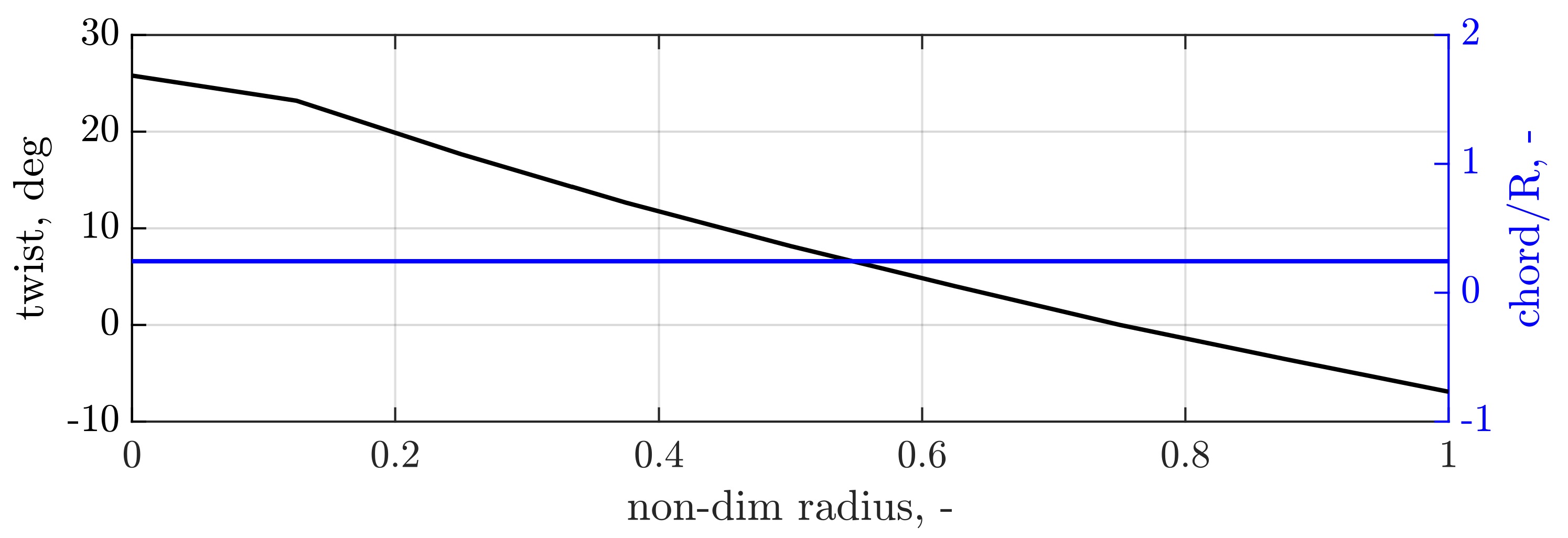
Both pylon and propeller blades are assumed to be rigid, whereas the mounting stiffness at the propeller’s pivoting point allows for pitch and yaw rotation modeling a flexible pylon system [9]. Consequently, a typical 2-degrees-of-freedom model for propeller whirl flutter, consistent with state-of-the-art practices, was established. The propeller blades are assumed to have a symmetrical NACA0012 airfoil. The blade geometrical parameters are presented in Figure 1 showing a linear twist and a constant chord distribution.
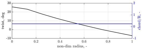
Figure 1.
Twist and chord distribution of propeller blade.
To facilitate the analysis in SDBox, unsteady propeller aerodynamics were precalculated by employing lifting line elements and wake particles in DUST. Determination of the unsteady propeller derivatives for various harmonic excitation frequencies was achieved using transfer functions with the methods presented by Koch et al. in refs. [7,8]. The validation of the standalone propeller–pylon model is presented in a previous work published by the authors. Specifically, the whirl flutter stability boundaries obtained in windmilling conditions have been computed in SDBox and with the coupled MBDyn–DUST tool, showing an excellent agreement (see Figure 11 from ref. [11]).
3.2. Coupled Multibody—Mid-Fidelity Aerodynamic Model
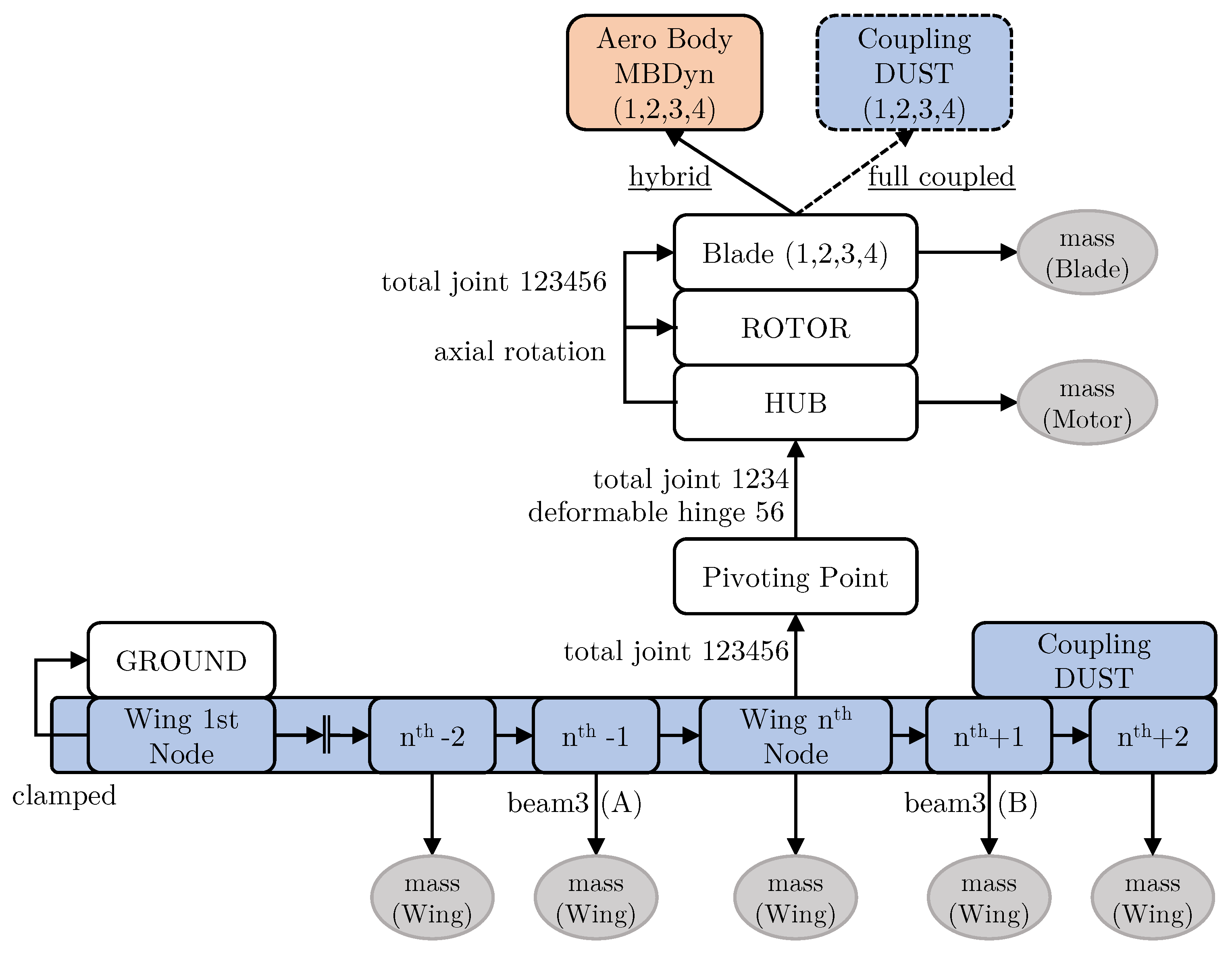
The corresponding wing-propeller models used for the hybrid and fully coupled analyses in MBDyn and DUST are described below. As given in Table 1, the structural components of the system are modeled in MBDyn. An overview of the model setup is given in Figure 2.
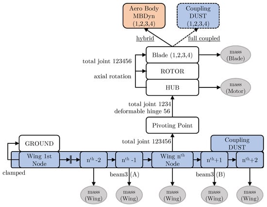
Figure 2.
Sketch of the coupled wing-propeller model in MBDyn–DUST.
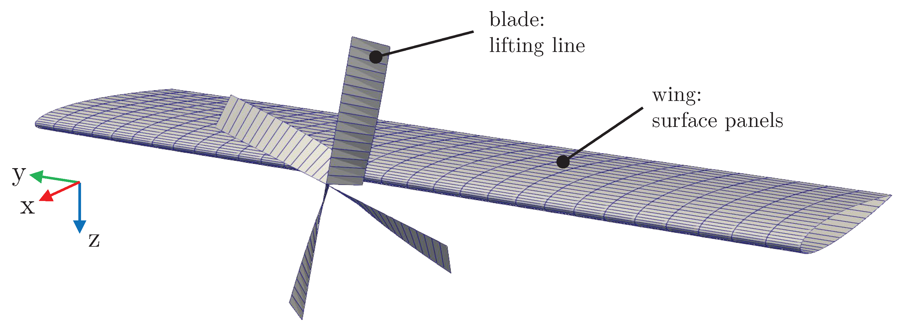
The wing elastic properties are modeled using three-node beam elements [29]. Structural damping for the wing is modeled with a proportional stiffness factor of 0.1%, such as for the corresponding SDBox model. The wing is clamped at its root. The mass and inertia properties of the wing are modeled using lumped masses at each structural node, accounting for the offset between the elastic axis and the center of gravity. In total, 41 nodes and 20 beam elements are used, allowing one to capture the low-frequency bending and torsional dynamics of the wing leading to the flutter. The propeller is attached at 50% of the wing semispan. The pivoting point of the propeller is rigidly connected to the nth node at a distance of chord from the elastic axis (i.e., towards the leading edge). The propeller hub is connected to the pivoting point through two joints: a total joint and a deformable hinge. The deformable hinge introduces the pylon rotational stiffnesses in yaw and pitch. Damping effects are neglected on this joint. The rotor node is located at the same position as the hub node. They are both connected via an axial rotation constraint, which enforces the rotation of the propeller. Additionally, four nodes are rigidly attached to the rotor node, representing the blades. The mass of the motor is connected to the hub node (non-rotating mass). Propeller blades are assumed to be rigid. The corresponding mass/inertia is lumped at the blade center of mass. For the hybrid approach, each blade is also connected to an aerodynamic body, representing the aerodynamic model in MBDyn. As previously mentioned, this model incorporates a propeller dynamic inflow and 3D correction factors such as tip loss correction. The chord and twist distributions are specified as input parameters. For the fully coupled approach, the nodes of the propeller are selected for coupling with DUST. Propeller aerodynamics in DUST are modeled using 16 lifting line elements on each blade (see Figure 3).
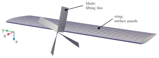
Figure 3.
DUST aerodynamic model for wing and propeller.
The aerodynamics of the wing are modeled in DUST for both the hybrid and the fully coupled approaches. Surface panels are employed to represent the wing’s geometry. The wing is discretized with 30 panels in the span direction and 20 panels in chord. To accurately capture the curvature of the leading edge, the chord distribution is discretized using a half-cosine function. The number of panels defined on the wing and lifting line elements on the propeller blades has been selected to capture the wing and propeller performance in steady conditions. A mesh-independent study was conducted to ensure the convergence of lift/moment coefficients for the wing and thrust/torque for the propeller.
For each coupling node, displacements, velocities, and accelerations are exchanged as well as the corresponding loads using the PreCICE coupling framework [25]. The interface between structural and aerodynamic grids is obtained as a weighted average of the distance between the nodes of the two grids and used for motion interpolation and consistent force and moment reduction. The tight coupling implicit scheme guarantees the convergence of loads and kinematic quantities at each time step.
The simulation process starts with the initialization of MBDyn and DUST. A checkpoint of the exchanged fields between the two codes is stored, to be reloaded during sub-iterations of preCICE’s implicit coupling. Subsequently, DUST receives the kinematic variables of the structural nodes from MBDyn and updates the surfaces of the coupled components and the near-field wake elements. The strength of the vortexes on the surface panels and the circulation on lifting lines is then computed, providing the aerodynamic loads. Aerodynamic forces and moments are reduced to the nodes of the interface between the aerodynamic and structural meshes and sent to MBDyn. A convergence check on the kinematic variables follows. If the convergence is not reached, the checkpoint fields are reloaded, and a new sub-iteration begins. Conversely, the simulation variables are saved while the geometry and the wake are updated for the next time step. The interested reader can find more details about the coupling process in ref. [26].
3.3. Operational Conditions
A trim condition must be established before conducting the flutter analysis. In this study, the trim is primarily defined by the propeller operational point, whereas the wing angle of attack and the corresponding lift generated are not considered trim parameters. This decision is based on the assumption that the wing flutter, in the subsonic regime, is a linear phenomenon depending on the lift perturbations rather than the lift generated at the reference condition. Furthermore, it must be remarked that the lift gradient with the angle of attack is constant at small angles of attack (i.e., at the higher flight speed where the flutter occurs), reinforcing the statement that the angle of attack at the trim condition and the corresponding lift generated remain negligible. Similarly, the choice of wing airfoil is expected to provide a second-order effect on the aeroelastic stability of the wing in subsonic regime [30].
This paper focuses on two distinct propeller conditions, listed in Table 6. The windmilling condition is chosen because it represents the most critical condition for propeller whirl flutter [31]. However, since the influence of the aerodynamic interaction between the propeller and wing on flutter is the object of the present study, a thrusting condition is also considered. Therefore, the thrust required by the aircraft is chosen as the trim point condition. Generally, the propeller’s operational point is a function of the free stream velocity, rotational speed (i.e., the propeller advance ratio), and the blades’ collective pitch angle. In this work, a constant propeller rotational speed is selected to maintain a constant angular momentum, while the free stream velocity is set as the initial condition. As a result, the only remaining parameter to achieve a trim condition is the collective pitch of the blades.
Table 6.
Operational conditions under investigation.
3.4. Tuning and Validation of the Standalone Propeller Model
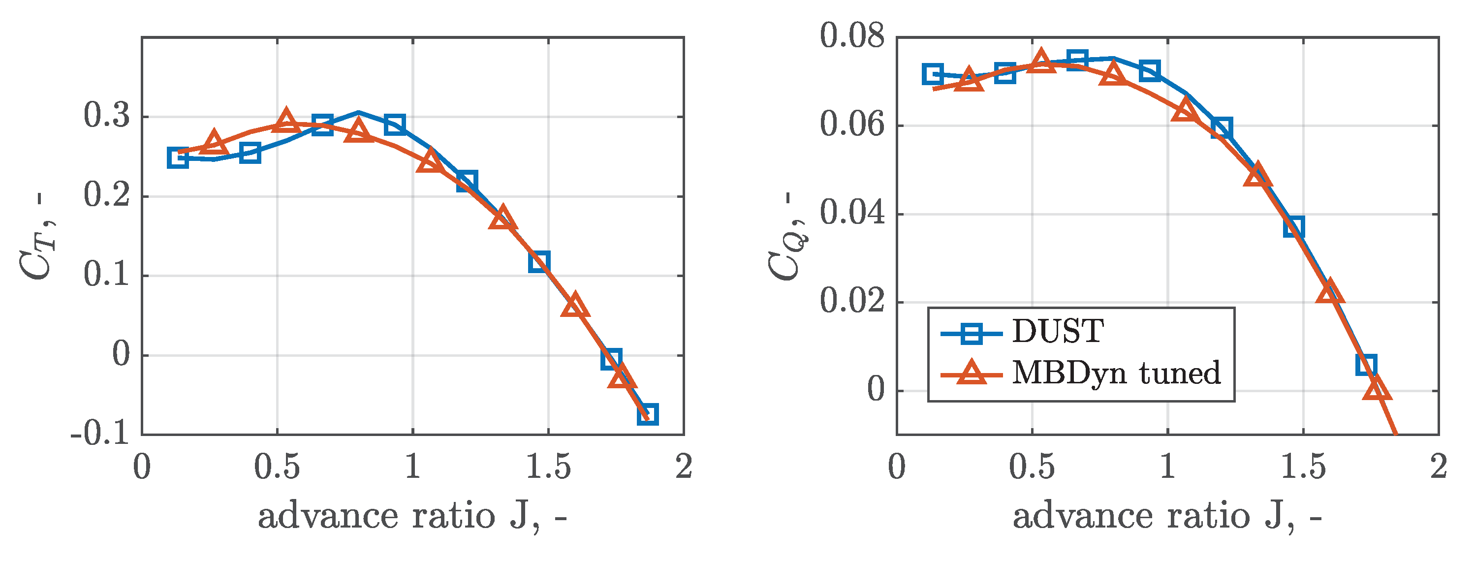
To ensure consistency in the aerodynamic modeling of the propeller, a comparison was conducted based on the two different time-domain analysis approaches. This was achieved by examining the performance curves for the standalone propeller without the presence of the wing. The thrust and torque coefficients with reference to the advance ratio for the simulations conducted using DUST and MBDyn are presented in Figure 4, considering a collective pitch angle of 38.2°. The aerodynamic model in MBDyn was tuned with a linear tip loss function to consider the three-dimensional effects on the blades and with an empirical correction factor ( = 1.3) on the dynamic inflow model to include the power losses. These modifications were required to match the thrust and torque curves obtained in DUST. As observed in Figure 4, both curves exhibit a perfect match, indicating a consistent aerodynamic modeling approach.
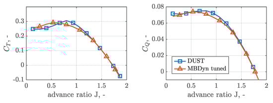
Figure 4.
Thrust coefficient (left) and torque coefficient (right) vs. advance ratio (J) for a collective pitch of 38.2°.
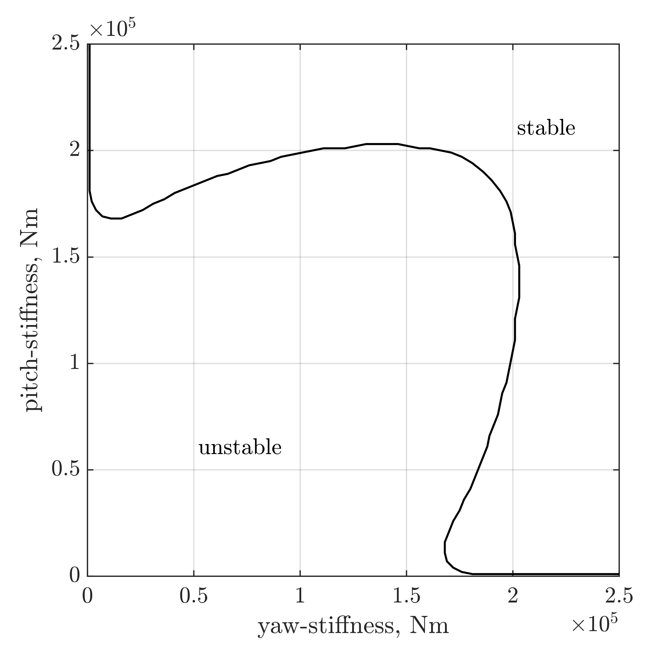
Additionally, the whirl flutter stability map for the standalone propeller was created in SDBox for a free stream velocity of 133 and windmilling condition (see Figure 5). As expected, the largest required stiffness is obtained at isotropic conditions, equal to 188,000 . The same conditions were analyzed using both time-domain approaches, i.e., hybrid and fully coupled. The time histories were post-processed using the matrix pencil estimation (MPE) to extract eigenfrequencies and damping ratios [32]. Results are summarized in Table 7, further supporting the aerodynamic consistency between the two proposed analysis approaches.
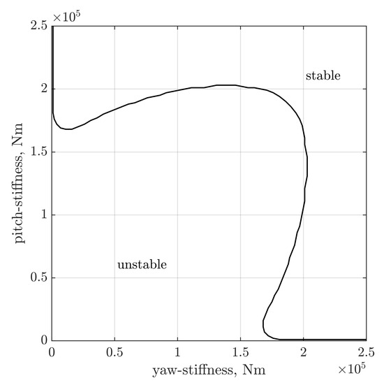
Figure 5.
Stability map for standalone propeller in SDBox (, , and collective pitch ).
Table 7.
Comparison of eigenfrequencies and damping ratios for the standalone propeller in MBDyn. Free stream velocity of 133 and isotropic stiffness of 188,000 .
3.5. Steady Aerodynamic Interaction
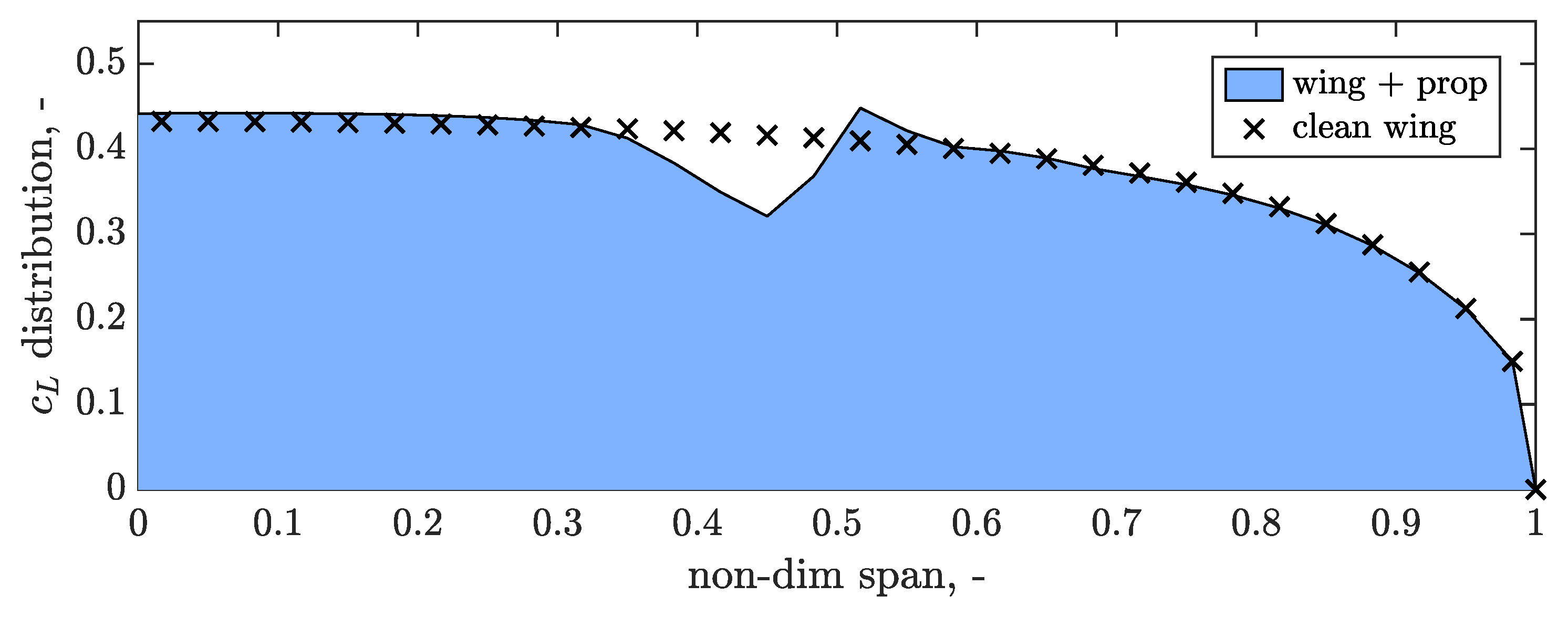
Since the aerodynamic interaction effect is the main focus of this study, a time-domain simulation of the clean wing and the wing-propeller system is performed in DUST to highlight the impact of aerodynamic interference on load distribution in a steady-state condition. The angle of attack is set to 5° with the propeller operating in the thrusting condition. Symmetry at the half-wing root is assumed, and the sectional loads are post-processed. For both simulations, the spanwise distribution of the wing is shown in Figure 6. The expected elliptical distribution is seen for the clean wing (dashed line). For the wing-propeller system (solid line), local peaks in sectional arise due to the propeller wake. The peak’s center corresponds to the hub span position of the propeller.
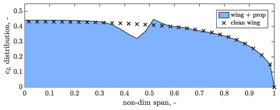
Figure 6.
The distribution of clean wing and wing with propeller attached at 50% span in thrusting condition at an angle of attack of 5°.
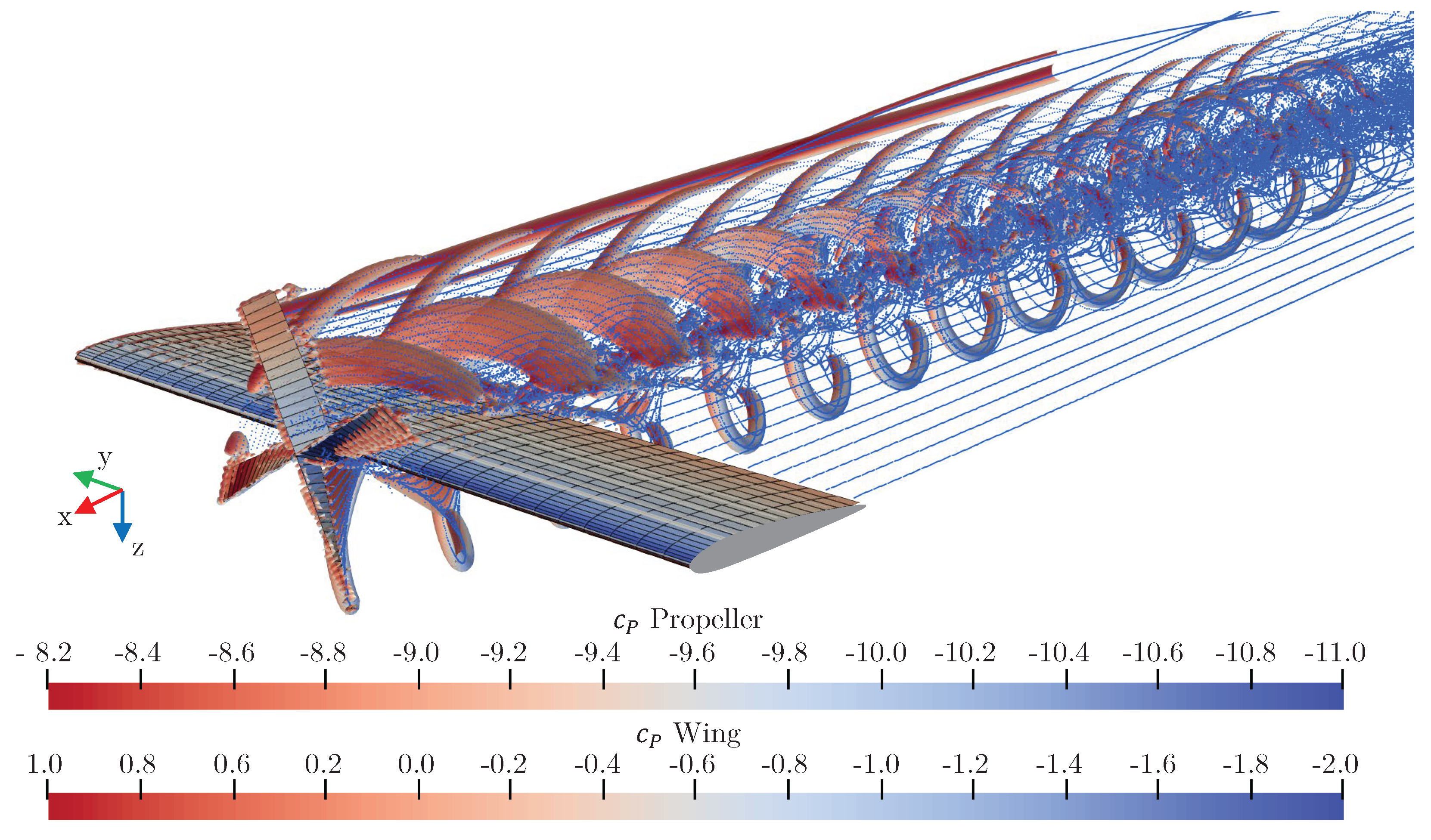
The behavior is similar to those found in the literature [33,34], with the low values for the up-moving half of the propeller disk and positive on the down-moving half. Figure 7 depicts the flow field of the coupled wing-propeller model through the iso-surfaces of the Q-criterion. The pressure coefficient contours are shown for both the propeller and the wing. The interactions of the propeller wake with the wing are clearly visible. High vortex areas are observed for the helical system generated by the propeller system and for the tip vortices of the wing.
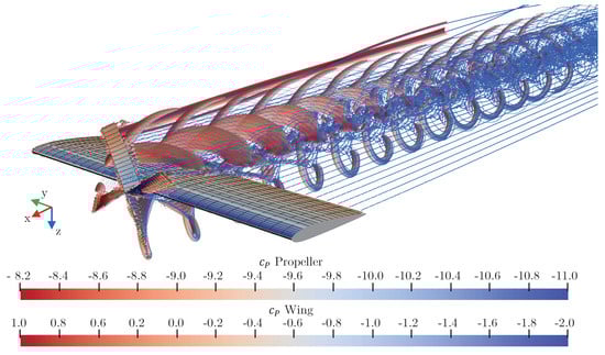
Figure 7.
Coupled simulation results of DUST for the wing-propeller system at 5° angle of attack. Iso-surface of Q-Criterion for flow filed. Pressure coefficient contours for the surfaces.
Aerodynamic interference acts on the propeller load distribution as well. Indeed, due to the presence of the wing, propeller performances are slightly altered. The next section, in particular, will show how the collective pitch has been corrected to match the windmilling and the thrusting conditions selected for the aeroelastic analyses, due to the upwash of the wing interfering with the propeller.
4. Results
This section presents the aeroelastic stability analysis results using both the hybrid and the fully coupled approaches. The simulation is performed by varying the free stream velocity and analyzing the wing-propeller response. Frequencies and damping ratios are extracted using the MPE method. First, the flutter predictions obtained with SDBox are introduced. Finally, the stability analysis results for both operational conditions are presented and discussed.
4.1. Preliminary Flutter Prediction
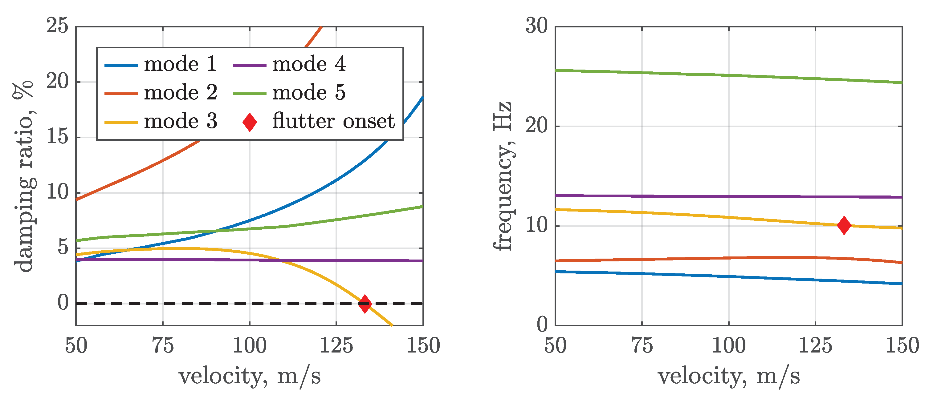
To establish an initial velocity range for flutter analysis, SDBox was employed to predict critical speeds for the wing-propeller system, with the propeller positioned at 50% of the semispan wing. The mounting stiffness of the propeller is set to 40,000 . The relatively low mounting stiffness is intentionally chosen to induce wing flutter within a realistic velocity range. In general, such low stiffness values can be considered a failure case of the pylon, where structural integrity is reduced. The propeller aerodynamics are modeled with precalculated unsteady propeller derivatives in windmilling conditions [11]. The resulting flutter curves are depicted in Figure 8. As shown by the red marker, flutter occurs at 133 triggered by mode 3. The corresponding flutter mode shape, presented in Figure 9, shows a strong coupling between the out-of-plane bending and the torsional motion of the wing. The propeller exhibits an elliptical backward whirl motion due to gyroscopic precession. This flutter mechanism is referred to as wing-dominant flutter [11] since the modal participation of the wing dynamics is dominant compared to the propeller motion.
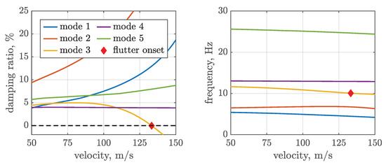
Figure 8.
Flutter curves (v-: left and v-f: right) for propeller at 50% span with 40,000 mounting stiffness.
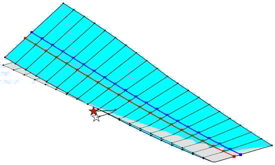
Figure 9.
Predicted flutter mode shape (mode 3) at 133 .
It should be highlighted that whirl flutter is not present for the configuration investigated, even though the mounting stiffness is smaller than the identified required stiffness for the stability of the standalone propeller (see Figure 5). This behavior is attributed to the stabilizing influence of the elastic wing on whirl flutter [31]. In the case of a rigid wing, whirl flutter would indeed occur.
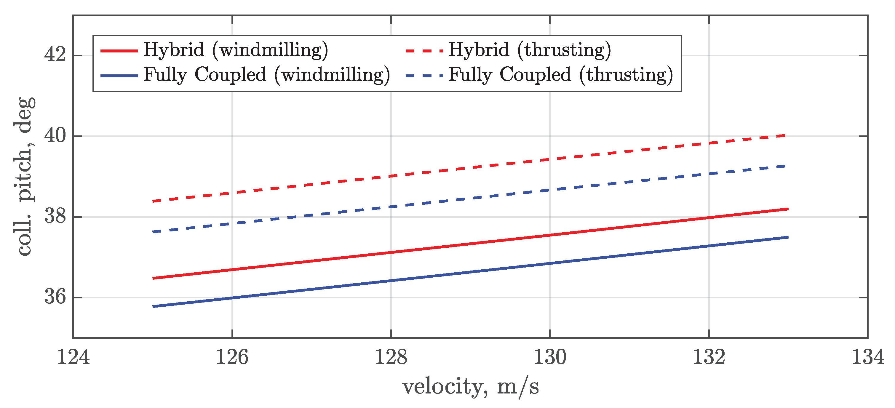
The predicted flutter speed was used to define the velocity range of interest for the time-marching analyses and the propeller trimming process. The required collective pitch angle for the propeller blades as a function of the free stream velocity was calculated based on performance curves of the standalone propeller (hybrid approach) and the wing-propeller system (fully coupled approach). The trim results are shown in Figure 10. The solid curves represent the windmilling condition, and the dashed curves are the thrusting condition. As expected, with increasing free stream velocity, the pitch angle to maintain the trim condition increases as well. The collective pitch angles for the thrusting case are higher compared to the windmilling condition. It is interesting to note that the trim angles for the fully coupled simulation (blue lines) are constantly smaller compared to the hybrid approach (red lines). The offset on the collective pitch is due to the aerodynamic interaction between the propeller and wing.
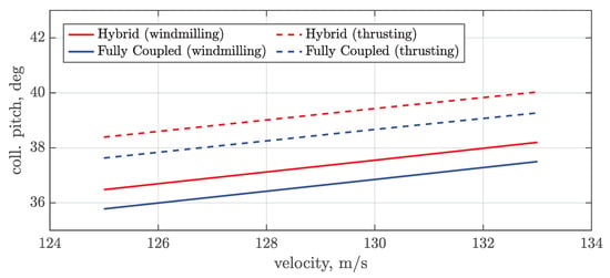
Figure 10.
Trim results to obtain the desired operational condition for the hybrid and fully coupled approach.
4.2. Stability Results with Aerodynamic Interference
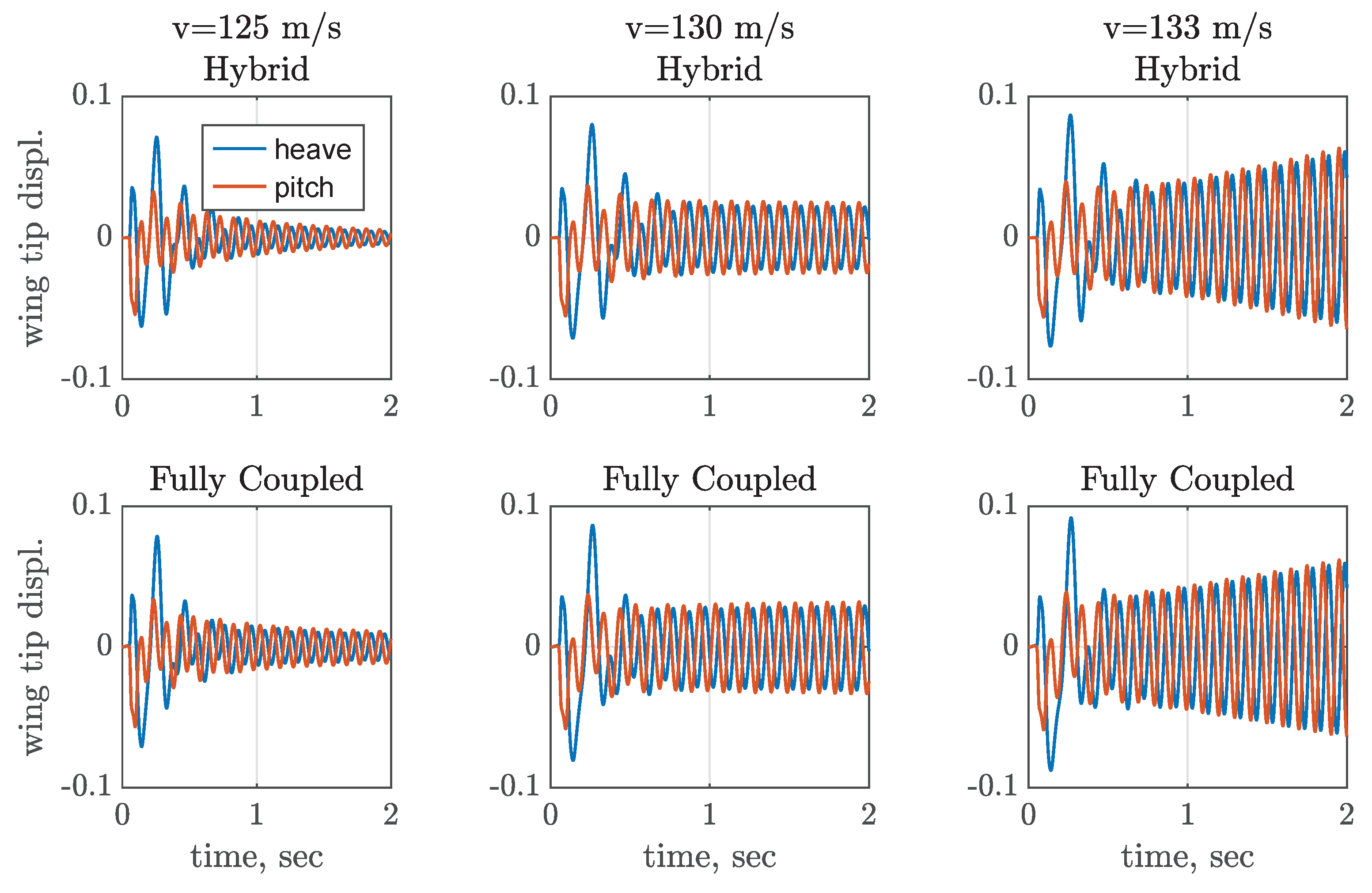
The stability results in MBDyn–DUST are presented in this section. The system is initially excited by a blended impulse force at the wing tip located before the elastic axis to excite both the out-of-plane bending and torsional dynamics. The blended impulse is applied within 2 and with an amplitude of 12 to ensure an excitation up to 30 Hz. The free response of the system, encompassing both aerodynamics and structural dynamics, was subsequently tracked. Three distinctive free stream velocities were simulated with the hybrid and the fully coupled approaches. The results for the windmilling condition are depicted in Figure 11.
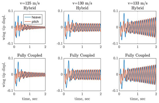
Figure 11.
Time histories of wing tip node for hybrid and fully coupled approach in windmilling condition.
Each plot represents the dynamic response of the wing’s tip node in pitch and heave. The figures on the top illustrate the response obtained with the hybrid approach, whereas the figures on the bottom display the response obtained with the fully coupled approach. At the beginning of the simulations, the transient behavior due to the blended impulse is observable. After a few milliseconds, most of the excited modes are damped due to aerodynamic effects. Subsequently, the poorly damped dynamic survives, which is used to identify the dynamic response characteristics. A preliminary stability assessment can be performed by visual inspection of the time histories. For both simulation approaches, an unstable behavior is observed at a free stream velocity of 133 . At 125 and 130 , the measured responses exhibit stable and indifferent behavior, respectively. The results of the MPE in the form of eigenfrequencies and damping ratios are summarized in Table 8.
Table 8.
Frequencies and damping ratios of the flutter mode in windmilling condition.
It should be noted that the MPE method often fails to accurately predict eigenfrequencies and damping ratios for highly damped modes. Consequently, only the poorly damped modes after the transient phase are identified. The comparison between the hybrid and the fully coupled approach reveals no significant difference, however, the fully coupled simulations return a slightly smaller flutter speed compared to the hybrid approach and SDBox. No large differences between the two analysis approaches can be observed, leading to the conclusion that the aerodynamic interaction effects in windmilling conditions are only minor in terms of stability.
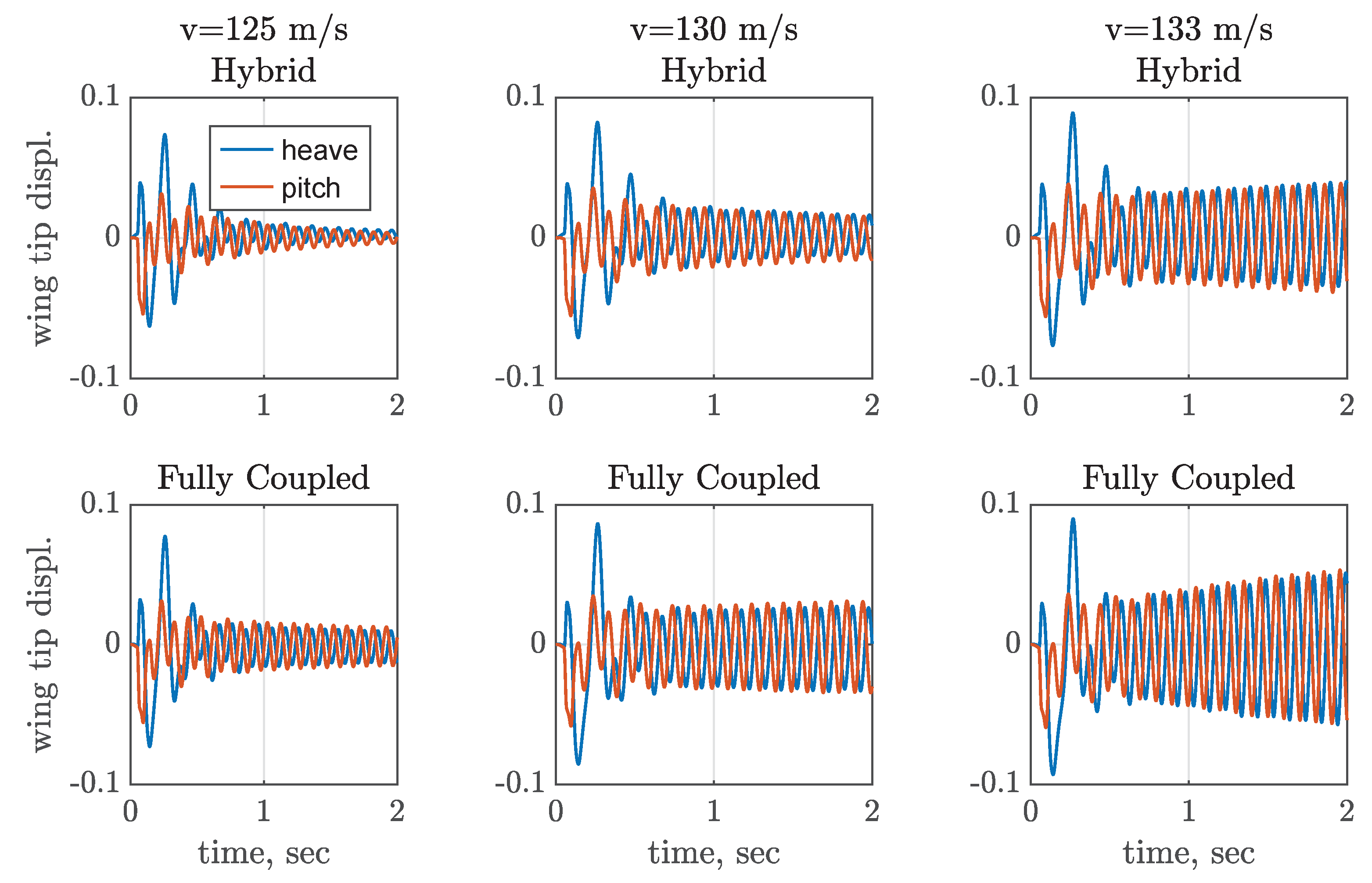
The time histories for the same free stream velocities, but for the thrusting propeller are presented in Figure 12. Again, stable and unstable behaviors are shown at 125 and 133 . Consequently, flutter is again covered within the velocity range considered.
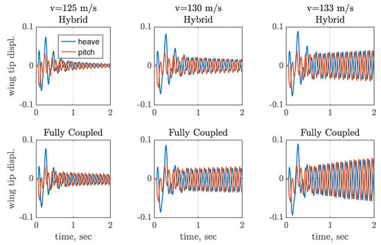
Figure 12.
Time histories of wing tip node for hybrid and fully coupled approach in thrusting condition.
In contrast to the windmilling condition, the comparison between the hybrid and fully coupled approaches reveals more pronounced differences in the response. Indeed, the fully coupled approach appears to be less stable across all velocities compared to the hybrid approach. These results are confirmed by the MPE method (see Table 9).
Table 9.
Frequencies and damping ratios of the flutter mode in thrusting condition.
The fully coupled approach returns an unstable condition at 130 . Consequently, the influence of the aerodynamic interaction on flutter is stronger in case of a thrusting operational condition. This effect can be attributed to the higher induced velocity generated by the propeller in thrusting conditions, leading to higher local dynamic pressures on the wing and, in turn, higher aerodynamic loads, reducing the flutter onset.
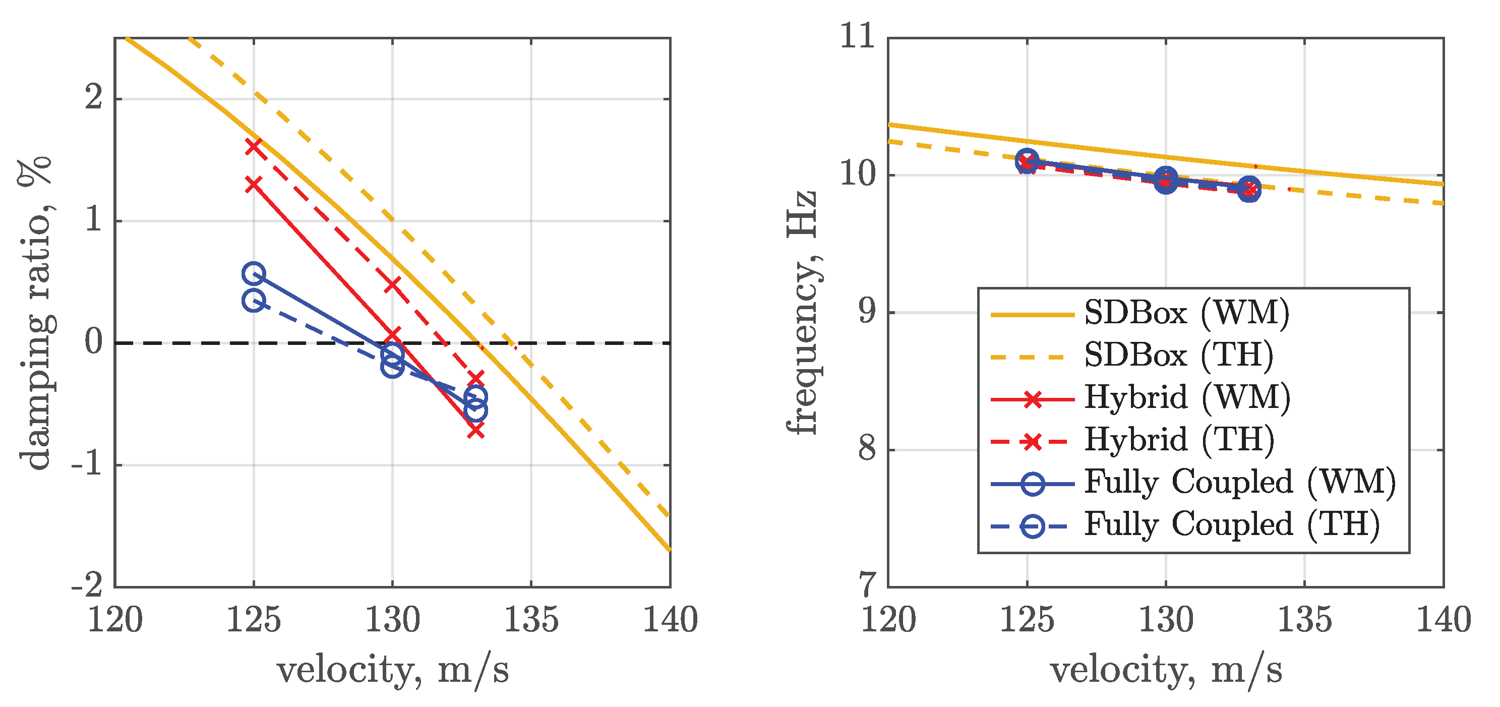
In summary, one can discern trends in damping and frequencies across the four combinations of time-domain approaches and trim conditions depicted in classical flutter curves. These trends are illustrated in Figure 13. The predicted flutter mode 3 by SDBox is also included for both trim conditions. Yellow, red-crossed, and blue-circled lines represent the SDBox, hybrid, and fully coupled approaches, respectively.
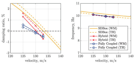
Figure 13.
Damping and frequency trends for unstable mode for all three simulation approaches.
Solid lines were obtained for the windmilling condition and dashed lines for the thrusting condition. The frequency of the critical mode aligns well with the prediction made by SDBox for mode 3, regardless of the trim condition. Additionally, the occurrence of flutter within the considered velocity range is accurately captured. Across all time-domain approaches, it is observed that the flutter speed is slightly overpredicted by SDBox. In contrast, the fully coupled approach (blue lines) always predicts the lowest flutter speed, irrespective of the trim condition. The largest difference between SDBox and the fully coupled approach in the flutter speed is 4.5% and 3.3% between the hybrid and the fully coupled approach for the thrusting case. Interestingly, it is noted that with the hybrid and SDBox approaches, the windmilling condition is predicted to be more critical than the thrusting condition. With the fully coupled approach, however, the situation is reversed. Last but not least, it must be remarked that, although the thrusting condition provides a stabilizing effect on whirl motion due to the propeller’s aerodynamic torque [9], the aerodynamic interactions between the wing and propeller return a stronger destabilizing effect, leading to a reduced flutter speed.
5. Conclusions
This paper presents original findings on the impact of aerodynamic interaction on aeroelastic stability within a wing-propeller system when considering selected operative conditions and proposes an efficient methodology based on coupled multibody–mid-fidelity aerodynamic simulations.
The focus is primarily on a flutter mechanism originating from the wing. A baseline model was established featuring a flexible wing and a mid-semispan mounted propeller with a flexible pylon and rigid blades. Flutter for this model was initially predicted using a frequency-domain method that neglected the aerodynamic interactions. To assess the impact of aerodynamic interference, coupled fluid-structure time-domain simulations were performed. Structural modeling was conducted using a multibody dynamics code (MBDyn). For the aerodynamic modeling, two different simulation approaches were defined. With the first approach (hybrid), the propeller aerodynamics were modeled separately from the wing aerodynamics, neglecting interference. Specifically, propeller aerodynamics were modeled using a blade element model together with a 3-state dynamic inflow model within MBDyn, whereas wing aerodynamics were modeled using a 3D panel method with a free wake particle description (DUST). With the second approach (fully coupled), both elements, i.e., the propeller and the wing, were aerodynamically modeled in DUST, with the propeller modeled using lifting line elements. The particle wake description in DUST allows us to consider aerodynamic interactions between the propeller and the wing. A time-marching scheme was applied to find the flutter point for both the hybrid and fully coupled approaches. Two trim points were selected: (1) windmilling and (2) thrusting. The former is known to be most critical for whirl flutter, and the latter represents a typical trim condition in steady-level flight. Trim conditions were ensured by varying the collective pitch of the propeller while holding the rotational speed constant. Time histories were obtained, and eigenfrequencies and damping ratios for the critical mode were extracted using the MPE method. The main findings of these studies are summarized as follows:
- The inclusion of aerodynamic wing-propeller interaction effects in aeroelastic stability analysis leads to reduced flutter speeds for both windmilling and thrusting cases. This is due to the propeller slipstream effect impacting the wing aerodynamics.
- Neglecting aerodynamic interference, the windmilling condition returns the smallest flutter boundaries. This behavior is also seen in the majority of the cases discussed in the literature for the standalone propeller.
- Including aerodynamic interference, the thrusting condition returns the smallest stability boundaries due to the increment of dynamic pressure and local lift on the wing induced by the propeller.
- The difference in the flutter speed for the analyzed configuration is less than 5% between the frequency-domain approach without aerodynamic interaction and the fully coupled approach. Therefore, the frequency-domain approach is preferable for preliminary analyses. It is faster than time-marching analyses and delivers accurate results, though the outcomes are not conservative regarding flutter speed.
These conclusions refer to a baseline model of a wing with a single propeller and can not be generalized, at this stage, to aircraft with different configurations. Nevertheless, this work introduces a robust workflow, based on efficient aeroelastic simulations, that can be exploited for the analysis of vehicles with distributed electric propulsive systems. The approach relies on several steps, including an extended validation of the single components and the coupled system, and provides initial guidelines for the aeroelastic design of wing-propeller systems. Naturally, conducting experimental test campaigns to verify the numerical predictions should be regarded as the final step for validation.
Further studies will investigate the impact of aerodynamic interference on a flexible wing with multiple propellers, representative of a powered-lift eVTOL, to understand if the aerodynamic interference has a small impact on flutter, as in the case of a single propeller, or leads to a significant reduction of the critical speed. In the last case, the usage of classical frequency methods for flutter prediction will not be reliable anymore and the inclusion of aerodynamic interference will become mandatory to predict the aircraft stability boundaries correctly.
Author Contributions
Conceptualization, N.B., C.B., P.M. and V.M.; methodology, N.B., C.B., P.M. and V.M.; software, N.B. and V.M.; validation, N.B. and V.M.; formal analysis, N.B.; investigation, N.B. and V.M.; resources, N.B., C.B., P.M. and V.M.; data curation, N.B. and V.M.; writing—original draft preparation, N.B. and V.M.; writing—review and editing, N.B., C.B., P.M. and V.M.; visualization, N.B. and V.M.; supervision, C.B., P.M. and V.M. All authors have read and agreed to the published version of the manuscript.
Funding
This research received no external funding.
Institutional Review Board Statement
Not applicable.
Informed Consent Statement
Not applicable.
Data Availability Statement
The original contributions presented in the study are included in the article, further inquiries can be directed to the corresponding author.
Conflicts of Interest
The authors declare no conflicts of interest.
Abbreviations
The following abbreviations are used in this manuscript:
| UAM | Urban Air Mobility |
| DEP | Distributed Electric Propulsion |
| eVTOL | Electric Vertical Take-Off and Landing |
| VPM | Vortex Particle Method |
| DLM | Doublet Lattice Method |
| FMM | Fast Multipole Method |
| MPE | Matrix Pencil Estimation |
| preCICE | Precise Code Interaction Coupling Environment |
| CSD | Computational Structural Dynamics |
| CFD | Computational Fluid Dynamics |
References
- De Vries, R.; Vos, R. Aerodynamic Performance Benefits of Over-the-Wing Distributed Propulsion for Hybrid-Electric Transport Aircraft. In Proceedings of the AIAA SciTech 2022 Forum, San Diego, CA, USA, & Virtual, 3–7 January 2022. [Google Scholar] [CrossRef]
- Stoll, A.M.; Bevirt, J.; Moore, M.D.; Fredericks, W.J.; Borer, N.K. Drag Reduction Through Distributed Electric Propulsion. In Proceedings of the 14th AIAA Aviation Technology, Integration, and Operations Conference, Atlanta, GA, USA, 16–20 June 2014. [Google Scholar] [CrossRef]
- Heeg, J.; Standford, B.K.; Kreshock, A.; Shen, J.; Hoover, C.B.; Truax, R. Whirl Flutter and the Development of the NASA X-57 MAXWELL. In Proceedings of the International Forum on Aeroelasticity and Structural Dynamics, Savannah, GA, USA, 10–13 June 2019. [Google Scholar]
- Zwaan, R.; Bergh, H. Propeller-Nacelle Flutter of the Lockheed Electra Aircraft; TR F.228; Nationaal Luchtvaartlaboratorium: Amsterdam, The Netherlands, 1962. [Google Scholar]
- Reed, W.H.; Bland, S.R. An Analytical Treatment of Aircraft Propeller Precession Instability; Technical Note D-659; Langley Reserach Center: Washington, DC, USA, 1961. [Google Scholar]
- Houbolt, J.C.; Reed, W.H. Propeller-Nacelle Whirl Flutter. J. Aerosp. Sci. 1962, 29, 333–346. [Google Scholar] [CrossRef]
- Koch, C. Whirl Flutter Stability Assessment Using Rotor Transfer Matrices. In Proceedings of the International Forum on Aeroelasticity and Structural Dynamics 2022, Madrid, Spain, 13–17 June 2022. [Google Scholar]
- Koch, C.; Böhnisch, N.; Verdonck, H.; Hach, O.; Braun, C. Comparison of Unsteady Low- and Mid-Fidelity Propeller Aerodynamic Methods for Whirl Flutter Applications. Appl. Sci. 2024, 14, 850. [Google Scholar] [CrossRef]
- Kantzidis, P.; Böhnisch, N.; Masarati, P.; Muscarello, V. About the Stabilizing Effect of the Torque on Propeller Whirl Flutter. In Proceedings of the VFS 80th Annual Forum, Montreal, QC, Canada, 7–9 May 2024. [Google Scholar]
- Bennett, R.M.; Bland, S.R. Experimental and Analytical Investigation of Propeller Whirl Flutter of a Power Plant on a Flexible Wing; Technical Report NASA-TN-D-2399; NASA Langley Research Center: Washington, DC, USA, 1964. [Google Scholar]
- Böhnisch, N.; Braun, C.; Muscarello, V.; Marzocca, P. About the Wing and Whirl Flutter of a Slender Wing–Propeller System. J. Aircr. 2024, 61, 1117–1130. [Google Scholar] [CrossRef]
- Teixeira, P.C.; Cesnik, C.E. Propeller Influence on the stability of HALE Aircraft. In Proceedings of the 31st Congress of the International Council of the Aeronautical Sciences, Belo Horizonte, Brazil, 9–14 September 2018. [Google Scholar]
- Quanlong, C.; Jinglong, H.; Haiwei, Y. Effect of Engine Thrust on Nonlinear Flutter of Wings. J. Vibroeng. 2013, 15, 1731–1739. [Google Scholar]
- Amoozgar, M.; Hall, M.; Dimitriadis, G.; Cooper, J.E. The Effect of Thrust Vectoring on Aeroelastic Stability of Electric Aircraft. In Proceedings of the AIAA SciTech Forum 2024, Orlando, FL, USA, 8–12 January 2024. [Google Scholar] [CrossRef]
- Guruswamy, G.P. Dynamic Aeroelasticity of Wings with Tip Propeller by Using Navier–Stokes Equations. AIAA J. 2019, 57, 3200–3205. [Google Scholar] [CrossRef]
- Böhnisch, N.; Braun, C.; Muscarello, V.; Marzocca, P. The Effect of Aerodynamic Interactions on Aeroelastic Stability in Wing-Propeller Systems. In Proceedings of the 20th International Forum on Aeroelasticity and Structural Dynamics (IFASD), The Hague, The Netherlands, 17–21 June 2024; pp. 1–16. [Google Scholar]
- Chang, J.C.; Sanghi, D.; Cesnik, C.E.S. Wing and Propeller Aerodynamic Interaction Effects on Whirl Flutter Instability. In Proceedings of the VFS 80th Annual Forum, Montreal, QC, Canada, 7–9 May 2024. [Google Scholar] [CrossRef]
- Rodden, W.P.; Rose, T.L. Propeller/Nacelle Whirl Flutter Addition to MSC/NASTRAN; Technical report; The MacNeal-Schwendler Corporation: Lowell, MA, USA, 1989. [Google Scholar]
- Masarati, P.; Morandini, M.; Mantegazza, P. An Efficient Formulation for General-Purpose Multibody/Multiphysics Analysis. J. Comput. Nonlinear Dyn. 2014, 9, 041001. [Google Scholar] [CrossRef]
- Zanotti, A.; Savino, A.; Palazzi, M.; Tugnoli, M.; Muscarello, V. Assessment of a Mid-Fidelity Numerical Approach for the Investigation of Tiltrotor Aerodynamics. Appl. Sci. 2021, 11, 3385. [Google Scholar] [CrossRef]
- Pitt, D.M.; Peters, D.A. Rotor Dynamic Inflow Derivatives and Time Constants from Various Inflow Models. In Proceedings of the 9th European Rotorcraft Forum, Stresa, Italy, 13–15 September 1983. [Google Scholar]
- Pitt, D.M.; Peters, D.A. Theoretical prediction of dynamic inflow derivatives. In Proceedings of the 6th European Rotorcraft and Powered Lift Aircraft Forum, Bristol, UK, 16–19 September 1980. [Google Scholar]
- Cottet, G.H.; Koumoutsakos, P.D. Vortex Methods: Theory and Practice; Cambridge University Press: Cambridge, UK, 2000. [Google Scholar]
- Winckelmans, G.S. Topics in Vortex Methods for the Computation of Three-and Two-Dimensional Incompressible Unsteady Flows. Ph.D. Thesis, California Institute of Technology, Pasadena, CA, USA, 1989. [Google Scholar]
- Chourdakis, G.; Davis, K.; Rodenberg, B.; Schulte, M.; Simonis, F.; Uekermann, B.; Abrams, G.; Bungartz, H.J.; Cheung Yau, L.; Desai, I.; et al. preCICE v2: A sustainable and user-friendly coupling library. Open Res. Eur. 2022, 2, 51. [Google Scholar] [CrossRef] [PubMed]
- Savino, A.; Cocco, A.; Zanotti, A.; Tugnoli, M.; Masarati, P.; Muscarello, V. Coupling Mid-Fidelity Aerodynamics and Multibody Dynamics for the Aeroelastic Analysis of Rotary-Wing Vehicles. Energies 2021, 14, 6979. [Google Scholar] [CrossRef]
- Cocco, A.; Savino, A. Tiltrotor Whirl-Flutter Assessment by Multifidelity Aerodynamic Models. In Proceedings of the AIAA SciTech Forum and Exposition, Orlando, FL, USA, 8–12 January 2024. [Google Scholar] [CrossRef]
- Savino, A.; Cocco, A.; Muscarello, V. Evaluation of Dynamic Loads and Performance Indexes in Tiltrotors using a Mid-Fidelity Aeroservoelastic Tool. Aerosp. Sci. Technol. 2024, 146, 108929. [Google Scholar] [CrossRef]
- Ghiringhelli, G.L.; Masarati, P.; Mantegazza, P. A Multi-Body Implementation of Finite Volume Beams. AIAA J. 2000, 38, 131–138. [Google Scholar] [CrossRef]
- Opgenoord, M.M.J.; Drela, M.; Willcox, K.E. Physics-Based Low-Order Model for Transonic Flutter Prediction. AIAA J. 2018, 56, 1519–1531. [Google Scholar] [CrossRef]
- Reed, W.H. Review of Propeller-Rotor Whirl Flutter; Technical Report NASA TR R-264; NASA Langley Research Center: Washington, DC, USA, 1967. [Google Scholar]
- Hua, Y.; Sarkar, T.K. Matrix Pencil Method for Estimating Parameters of Exponentially Damped/Undamped Sinusoids in Noise. IEEE Trans. Acoust. Speech Signal Process. 1990, 38, 814–824. [Google Scholar] [CrossRef]
- Veldhuis, L.L.M. Propeller Wing Aerodynamic Interference. Ph.D. Thesis, Delft University of Technology, Delft, The Netherlands, 2005. [Google Scholar]
- Aref, P.; Ghoreyshi, M.; Jirasek, A.; Satchell, M.; Bergeron, K. Computational Study of Propeller–Wing Aerodynamic Interaction. Aerospace 2018, 5, 79. [Google Scholar] [CrossRef]

Disclaimer/Publisher’s Note: The statements, opinions and data contained in all publications are solely those of the individual author(s) and contributor(s) and not of MDPI and/or the editor(s). MDPI and/or the editor(s) disclaim responsibility for any injury to people or property resulting from any ideas, methods, instructions or products referred to in the content. |
© 2024 by the authors. Licensee MDPI, Basel, Switzerland. This article is an open access article distributed under the terms and conditions of the Creative Commons Attribution (CC BY) license (https://creativecommons.org/licenses/by/4.0/).