Article

Application of the Extension Strain Criterion for Sandstone Failure Evaluation under Tension and Shear Stress Conditions

Faculty of Civil Engineering and Resource Management, AGH University of Krakow, Mickiewicza 30, 30-059 Cracow, Poland
Appl. Sci. 2024, 14(19), 8953; https://doi.org/10.3390/app14198953
Submission received: 7 September 2024 / Revised: 27 September 2024 / Accepted: 30 September 2024 / Published: 4 October 2024
(This article belongs to the Section Civil Engineering)

Abstract

:
The article discusses the possibility of analysing, in geomechanical terms, the applicability of the extension strain criterion to assessing the fracture and failure process of sandstone samples. The results of laboratory tests of indirect tension, as well as uniaxial and triaxial compression were used to identify various forms of the criterion. The criterion parameters for fracture initiation and advanced failure processes were presented, and the results in both cases are different. The possible ways of applying this criterion to assess crack initiation in a tension test and failure in a shear test were also presented. Digital image correlation (DIC) analyses were used to determine the deformations of sandstone samples in both test types. The results of these studies show the possibilities to use this condition, e.g., to assess the stability of large-diameter boreholes (for disposal of radioactive waste) and wellbore stability, and to monitor and track the behaviour of tunnels drilled in strong rocks.

1. Introduction

The extension strain criterion condition first appeared in a publication by Stacey [1], according to whom the initiation of the rock fracture process can be predicted by tracking extension strains under appropriate stress conditions. As Stacey pointed out, while this condition depends on the rock type for the occurrence of crack initiation, the state of stress—low confinement in the vicinity of excavations in the rock—is also very important. It should be noted that this condition is dedicated to strong and brittle rocks. The criterion has been used repeatedly to evaluate crack initiation in tunnel walls in strong rocks [2,3,4] and to describe the excavation damage zone and the Äspö pillar stability [5]. The extension strain criterion can explain the reason why rock spalling begins in the tunnel wall when the compressive stress in the wall reaches approximately 0.4 times the uniaxial compressive strength (UCS) of the rock [3]. This phenomenon in tunnels has been observed and recorded numerous times [3,6,7,8,9,10]. It should be noted that spalling phenomena are specific, as the conditions for their occurrence are unique, and the rupture process is local. The extension strain criterion has also been used to analyse the stability of large-diameter boreholes in radioactive waste disposal sites, [11] wellbore stability [12], as well as to explain slabbing phenomena in strong pillars, the thighs of underground galleries, and colluviums [9], or ultimately to explain natural vertical fractures in mountain peaks [6].
Since the extension strain criterion, as given by Stacey, mainly refers to the fracture process, when identifying it, various authors generally use tensile or uniaxial compression tests where the phenomena of cracking or axial splitting are dominant and visible even before the limiting strength is reached. In identifying this condition, one can also find attempts at inverse analyses [5] or calibration on in situ observations and measurements [13].
However, the extension strain criterion has also been treated as a classical strength condition [14,15,16], describing the macroscopic failure of rock samples under saline stress conditions. Then, tensile, uniaxial and triaxial compression tests, and extreme extension strain values corresponding to the strength limit of rock samples are used to determine this condition.
In summary, two forms of the extension strain criterion can be noted, the first being applied to describe the initiation of the fracture process locally, i.e., at the micro level, as suggested by Stacey [1], and the second serving as a failure criterion at the macroscopic level of the rock sample. Therefore, the experimental identification of the condition is based on various experiments that produce different results.
The identification method proposed by Stacey is based on uniaxial compression tests and on tracking transverse deformation in rock samples. The crack initiation threshold has been studied by many researchers and determined by other methods, such as crack volumetric strain [17,18] or Poisson’s ratio [18]. Nevertheless, the first method to determine the threshold corresponding to the initiation of micro-cracking was proposed by Brace [19] who recommended volumetric strain analysis in rocks.
Tensile tests of rock samples are another very popular method for identifying crack initiation conditions. There are multiple methods of testing rocks under tensile conditions [20] yielding different results [21]. Depending on the rock type, the lowest values are obtained from the direct tension test, while the Brazilian test provides higher values. Due to its simplicity, the latter constitutes the most popular rock tension test. The methodology for conducting the Brazilian test is very important because different results are obtained with different loading patterns [20]. Although several Brazilian loading schemes are recommended, depending on the rock type, various failure mechanisms of specimens and tensile strength values can occur. In soft rocks, a mixed mechanism may occur, where shear will occur first in the region of loading platens, followed by tension inside the specimen. The mechanism of failure is important in analysing the occurrence of deformation in the test specimen [21].
The article presents various methods for identifying the extension strain criterion, resulting from both forms of the condition, at the micro level—for evaluating fracture initiation—and at the macro level—as a failure condition. The first part presents the identification of the extension strain criterion for evaluating the initiation of the fracture process in the sandstone samples obtained from a tunnel in Lubon (southern Poland). The results of the uniaxial compression and Brazilian tensile strength tests were used for this purpose. The results of identifying the criterion directly from the methodology proposed by Stacey, with the determination of crack initiation (CI) thresholds using different methods, and the results of determining the extension strain in the Brazilian test are also presented. Triaxial compression tests were also performed for the sandstone under analysis, which, together with the uniaxial tests, made it possible to determine the extension strain criterion treated as a strength condition [14].
In the final part of the article, both conditions were used to describe the fracture process of the sandstone sample in the Brazilian test and to illustrate the failure of the sandstone sample in the simple shear test. In these tests, digital image correlation (DIC) tools were used to track the deformation process. The results of these analyses are promising, as they indicate, on the one hand, a suitable methodology for identifying the condition, and, on the other, its potential application.

2. Methods and Materials

2.1. Methods

All investigations were carried out on a servo-controlled Rock and Concrete Mechanics Testing System (MTS) (Figure 1), with the triaxial tests additionally using the MTS (MTS Systems, Eden Prairie, MN, USA) triaxial cell, model 656.11 (Figure 1c). The measurement of the axial force was carried out with a force transducer MTS (MTS Systems, Eden Prairie, MN, USA) type 661.23 with a force capacity of 500 kN (Figure 1a,b). In the case of triaxial tests installed inside the pressure cell, model MTS 661.97B-02 (MTS Systems, Eden Prairie, MN, USA) with axial rated force capacities of 1532 kN (Figure 1c) was used, while the displacements were measured with the use of extensometers MTS type 632.90F-04 Kit 01 (MTS Systems, Eden Prairie, MN, USA) (Figure 1a–c). Radial displacements were determined through the measurement of changes in the sample circumference with a chain put around it. All tests were conducted according to the International Society for Rock Mechanics (ISRM) suggested methods [22] and ASTM standards [23]. The testing was conducted at room temperature and humidity, with the axial strain rate of 5 × 10⁻⁵ s−1 in all the compression experiments.
The triaxial testing procedure was as follows: After placing the sample inside the triaxial cell and filling it with mineral oil, confining pressure was applied until the desired value was reached (Figure 1d). Then, the axial force impacting the piston of the cell was increased to induce sample failure. Finally, axial force and confining pressure were reduced to zero at the end of the test.
In the second part of the article, presenting the applicability of the extension strain criterion to evaluate the failure process of sandstone samples, DIC analyses, simple shear, and Brazilian tensile strength tests were used. The camera used in the experiment was Nikon D60 (Nikon Corporation, Tokyo, Japan) (10Mpx, 3872 x 2592 px). Regarding the DIC method, the Ncorr system was applied [24].
To ensure the compatibility of the DIC analysis with the extensometer sensor measurement results, a comparison of the tensile stress–tensile strain curve obtained with the MTS extensometer and the DIC analysis (a virtual extensometer) is shown in Figure 2c. It can be seen that there is a good concordance between the two methods used to analyse strain in the specimen in the Brazilian test. Finally, three measurement methods were used simultaneously in these two tests: (1) an extensometer to measure crack width displacement in the Brazilian test, (2) a linear variable differential transformer (LVDT) sensor to measure piston displacement under a vertical load in the shear test, and (3) DIC to analyse the strain field on the lateral surface of the specimens (Figure 2a,b) in the Brazilian and shear tests.

2.2. Materials and Preliminary Results

The fine-grained sandstone rock samples were prepared through a process of diamond sawing and end lathing of rock block (Figure 3a) taken from a Lubon tunnel. No preliminary selection of samples was conducted to obtain their natural variability of properties (Figure 3b). In the case of UCS and triaxial tests, samples were right circular cylinders having a height–to–diameter ratio approximately equal to 2.0. In the case of tensile strength tests, samples were circular cylinders having a thickness (height) approximately equal to the specimen radius. The ends of the cylinder sample were flat, and the sides were smooth and straight over the full length of the sample. Twelve samples of sandstone (h = 110 mm, d = 55 mm) were subjected to compression tests, including five samples intended for unconfined (UCS) tests (σ1 > σ2 = σ3 = 0), and seven for conventional confined compression tests (σ1 > σ2 = σ3 = p > 0). The confined (triaxial) compression tests were carried out at confining pressures equal to p = 2.5, 5, 10, and 15 MPa, according to the loading scheme shown in Figure 1d. The preliminary test results obtained for all 17 sandstone samples are summarised in Table 1 and in Figure 3. Figure 3b shows the longitudinal wave velocity histogram obtained for fine-grained sandstone samples cut from a rock block. Longitudinal velocity can be a good measure of the heterogeneity of the studied rocks. The results show a homogeneous group of rock samples. Figure 3c,e show the stress-strain characteristics for all the specimens included in the Brazilian test (Figure 3c), in the uniaxial compression test (Figure 3d), and in the triaxial compression test (Figure 3e).
The preliminary strength results obtained for all 17 sandstone samples are summarised in Table 1. The designations σ1 and ε1 are the critical stresses and axial strains of the specimens corresponding to failure. The designation εTc for the compression case corresponds to the critical transverse deformation of the specimens. For tensile in the Brazilian test, the designation corresponds to the deformation in the direction perpendicular to the acting force.
In addition, density, longitudinal wave velocity, Young’s modulus E, and Poisson’s ratio ν are summarized in Table 1.

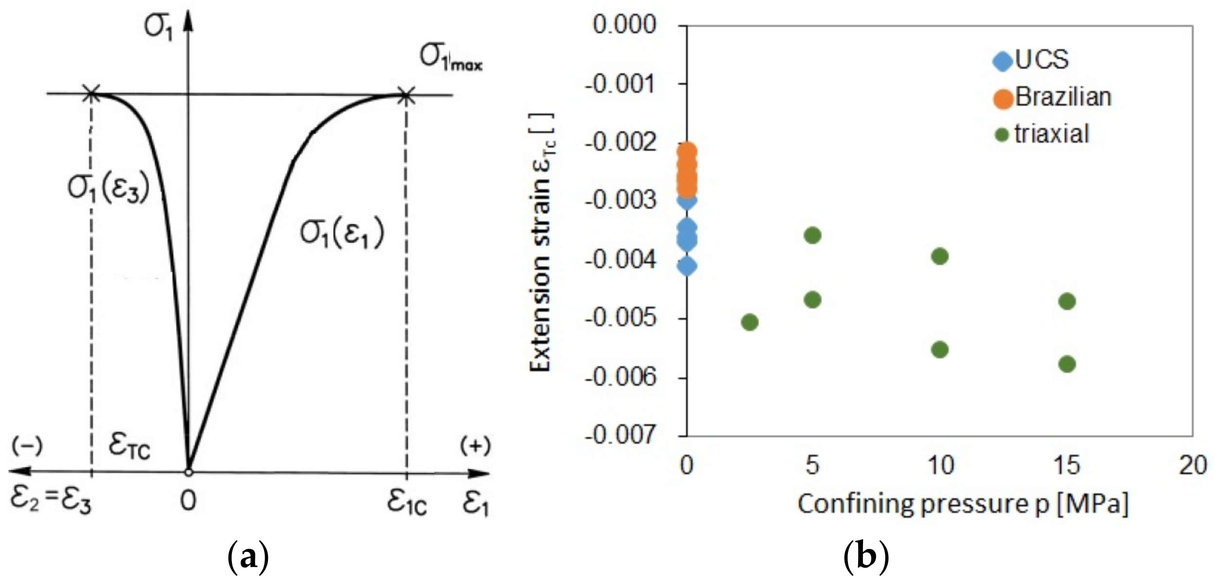
3. Stacey’s Extension Strain Criterion

In its original form, the criterion given by Stacey [1] reads as follows: “Fracture of a brittle rock will initiate when total tensile strain ε in the rock exceeds the critical value that is characteristic of that type of rock”. According to this criterion, fracture initiates when the following condition in Equation (1) is met:
ε     ε c ,
where ε c   is the critical value of the extension strain. It should be noted that, in geomechanical analyses of laboratory tests, the strains corresponding to compression are usually assumed to be positive while those corresponding to tension are assumed to be negative. As a consequence of that assumption, fracture will be initiated in a plane that is perpendicular to the direction of the extension strain, i.e., the direction of the least principal stress (σ1 > σ2 > σ3).
Importantly, Stacey suggests that the critical value of the extension strain should be determined based on the uniaxial compression tests of specimens and tracking the relationship between the radial strain (extension strain) and the axial strain. Minor changes in the curve’s slope can be identified as macro-scale fracturing in the samples. Based on the UCS characteristics (Figure 2b), the dependence of the radial strain on the axial strain in the first loading phase of the sandstone samples under analysis is shown (Figure 4). However, it is difficult to indicate the change in the curve’s slope in these graphs to identify the strain value corresponding to fracture initiation. Therefore, the critical extension strain was not determined using this method.

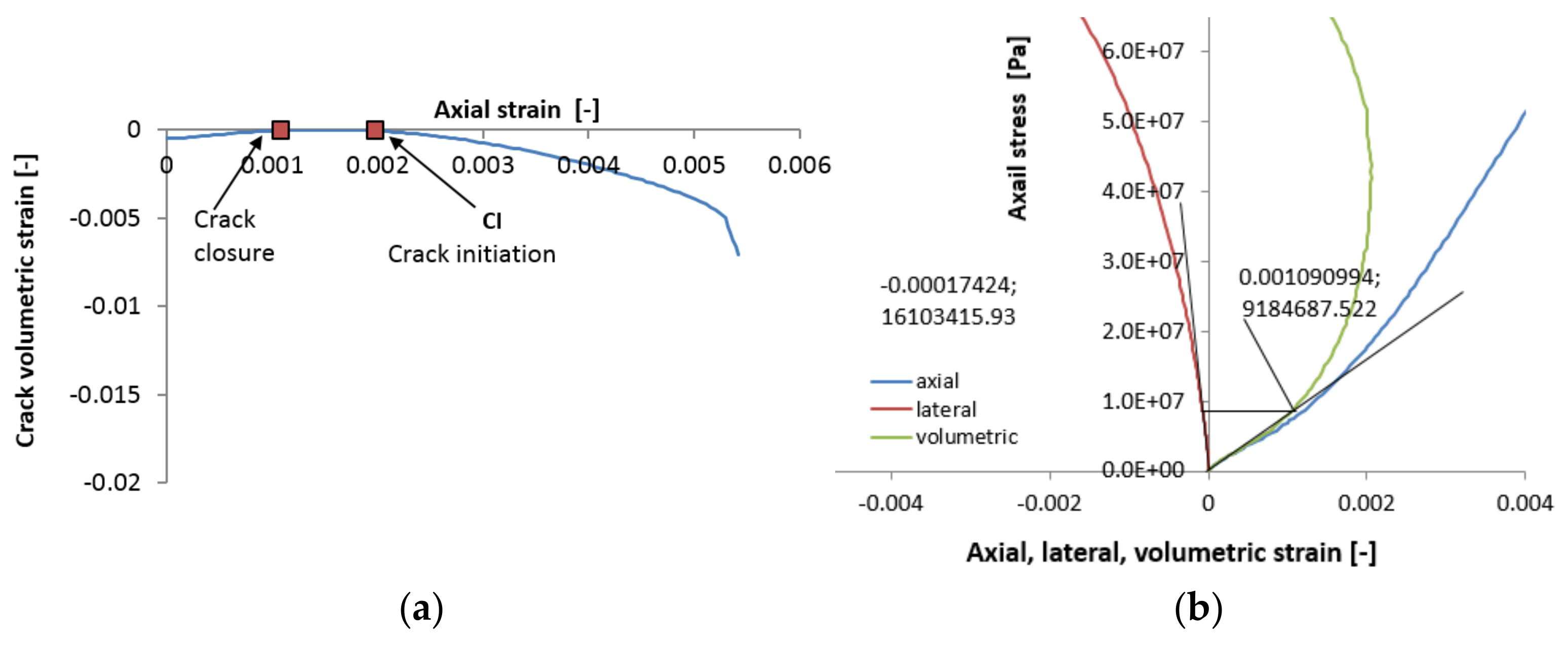
4. The Crack Initiation Threshold as an Extension Strain Criterion in Uniaxial Compression Tests

4.1. Assumptions of the Analyses

The extension strain criterion can also be determined based on the crack initiation threshold CI derived from uniaxial compression tests [17,18,19]. The crack initiation stress, i.e., the CI value that corresponds to the extension crack damage threshold, is the in situ strength of the rock in low confinement. This threshold corresponds to the interaction effect of internal flaws and heterogeneity [25]. Crack initiation is the onset of non-linearity on the lateral strain–axial stress plot [26]. The ISRM Commission on Spalling Prediction recommends the terminology of crack initiation to refer to the CI threshold and crack damage to refer to the crack interaction threshold [26].
In addition to the aforementioned lateral strain–axial stress relationship, CI can be determined using other methods, e.g., based on volumetric strain [19], crack volumetric strain Equations (2) (4) [18], or Poisson’s ratio [8,18].
For example, Figure 5 for the UCS tests shows the results of identifying the CI threshold using the crack volumetric strain method (Figure 5a) and based on the volumetric strain and lateral strain–axial stress relationships (Figure 5b)
ε v c r a c k = ε v ε e t a s t i c
ε v = ε a x i a l + 2 ε l a t e r a l
ε v e l a t i c = 1 2 ν E σ a x i a l

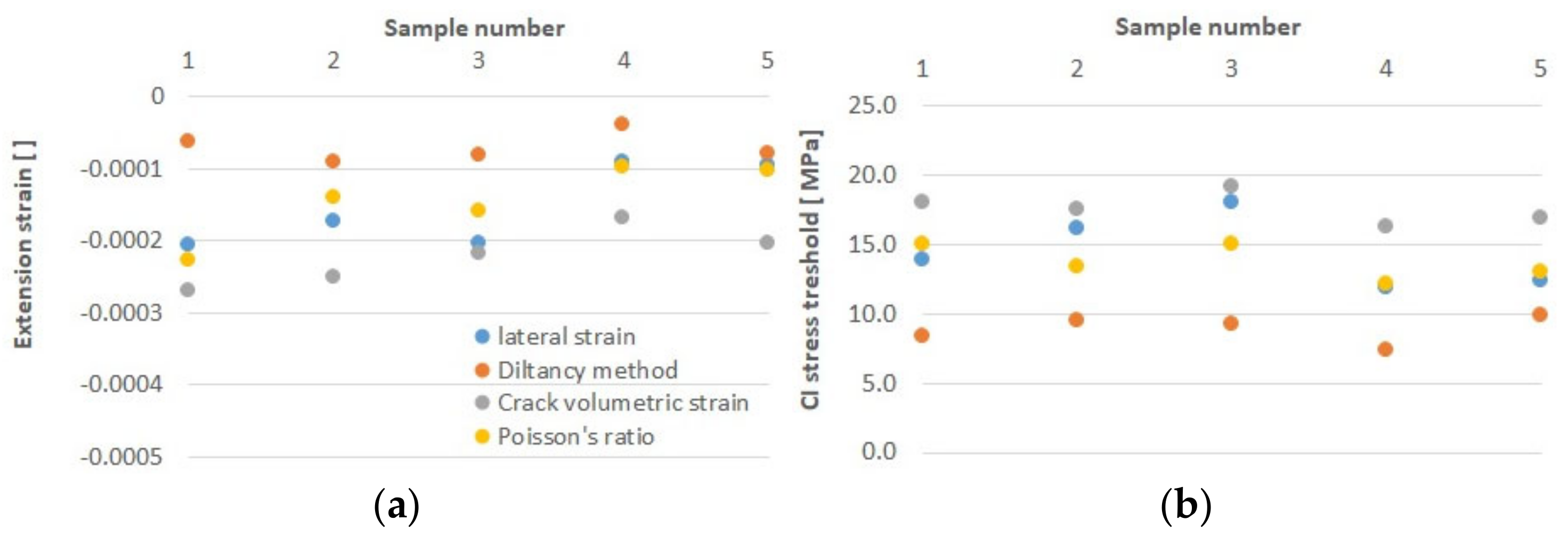
4.2. Discussion of the Results

A summary of the laboratory results for the UCS and the extension strain criterion corresponding to the crack initiation stress is given in Table 2 and Figure 6. As can be noted, regardless of the method for determining the CI threshold, the obtained values are similar. The corresponding values of the extension strain εext reflect the crack initiation criterion for the sandstone under analysis. According to the literature [5,19], the CI range related to UCS usually ranges between 0.3–0.5 UCS. In the case of the sandstone under analysis, this value corresponds to 0.2 UCS for Poisson’s ratio method, to 0.21 UCS for the lateral strain method, and to 0.25 UCS for the crack volumetric strain method, respectively.
The extension strain criterion values obtained using the lateral strain method, the crack volumetric method, or Poisson’s ratio method are similar and within the range of the results given by Stacey [1] for various rocks. The dilatancy method for the sandstone under analysis yielded the lowest value of the extension strain criterion and differed from the other results. It should be noted that the crack volumetric method is most often used in the literature on the subject to determine the CI threshold [17,18].
Referring to the crack volumetric strain method, the CI thresholds for triaxial test results were also determined. They were compared with compressive strength for all test circular pressures and UCS (Figure 7). The slope of the best-fit CI was determined using the least squares approximation method:
σ 1 = 0.26 σ c + 1.83 σ 3
Equation (5) is basically consistent with the results obtained by other researchers [5] based on which the damage initiation surface in the σ1–σ3 space can be approximated with Equation (6):
σ 1 = 0.4 σ c + ( 1.5 ÷ 2.0 ) σ 3
The value of 0.26σc for the tested sandstone under UCS conditions deviates from the literature results, but the dependence on σ3 is within the specified range.

5. The Application of Tensile Strength Tests’ Results to Determine the Extension Strain Criterion

5.1. Assumptions of the Analyses

The extension strain criterion was also determined based on the tensile strength tests using the Brazilian method. Based on Li’s findings [21], the following analysis can be conducted. For isotropic and ideal linear elastic materials, the strain is related to the three principal stresses (σ1, σ2, σ3), using the following Equation (7):
ε 3 = 1 E σ 3 ν σ 1 + σ 2
where E is Young’s modulus and ν is Poisson’s ratio. At the central point of the sample’s cross-section with radius R and thickness t, the values of σ3 and σ1 are as follows: σ3 = P/πRt, σ1 = –3P/πRt, σ2= 0 [21,27]. After substituting it with Equation (7), Equation (8) is obtained:
ε 3 = 1 + 3 ν E   P π R t
where P corresponds to the value of the maximum force in the Brazilian test. This analysis determines the elastic deformation corresponding to the tensile strength σT occurring in the centre of the tensile rock disk. This is appropriate for very strong, very stiff, and very brittle rocks. However, very often, it can be observed that the initiation of fracture does not begin in the centre of the disk but is shifted towards the loading platen. The failure mechanism plays an important role here, especially in the case of weaker rocks [21].

5.2. Discussion of the Results

Although the tensile test, according to the ISRM [22] or ASTM [23] guidelines, ends immediately after the maximum force is applied, looking at the tensile characteristics of sandstone samples (Figure 2a) shows that they are not linear, especially in the last loading phase. It can be assumed that in the case of the sandstone under analysis, stress concentration near the loading platen (Figure 8 red circles) leads to an early shear failure fracture in the rock [28,29].
The analysis method according to Equation (8) is adopted, and the extension strain values corresponding to Stacey’s criterion obtained for Brazilian sandstone tests are shown in Table 3.
It can be noted that these values differ from those obtained in the UCS tests and are about three times higher. This may have resulted from the failure mechanism in the Brazilian sandstone test, which shows shearing in the loading platen region. For the sandstone studied, these values differ significantly from those also obtained by other authors [1,21]. In this case, the method cannot be recommended for obtaining the extension strain criterion values corresponding to Stacey’s criterion.

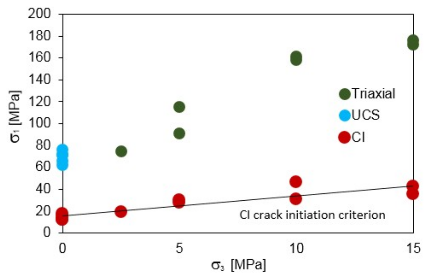
6. The Extension Strain Criterion as a Macroscopic Rock Sample Failure Condition

6.1. Assumptions of the Analyses

The second form of the extension strain criterion is the macroscopic description of sample failure given by Fujii et al. [14], originally named the “critical tensile strain criterion”. Based on this criterion, rock destruction occurs when the minimum principal strain (extension) reaches a critical value (ε3TC) understood as extension strain value ε3TC at the limit of strength (Figure 9a). Fujii’s criterion differs from Stacey’s criterion in the definition of the critical value of the extension strain. For Stacey, it is a certain value corresponding to the CI threshold, while for Fujii, it is the extension strain value ε3TC at the strength limit. In addition, critical extension strain value ε3TC, as defined by Fujii, is the total tensile strain, and it contains both elastic and inelastic strain components.
Figure 9a schematically shows the methodology for identifying the extension strain criterion based on the radial strain plots of the specimens in the UCS test and all the results obtained for the UCS, triaxial compression, and Brazilian tests as a function of confining pressure p (Figure 9b). The data on which the graphs were based can be found in Table 1.

6.2. Discussion of the Results

As can be noted, the extension strain εTC values obtained in the UCS and Brazilian tests differ significantly. In the case of UCS, the value falls within the interval of εTC = −0.003 ÷ −0.004, while the Brazilian test value range is εTC = −0.002 ÷ −0.003. Considering the results of triaxial tests, the limiting value of the extension strain additionally depends on the confining pressure, i.e., it is pressure sensitive. This conclusion was also confirmed in a study by Kwasniewski and Takahashi [15]. However, it should be borne in mind that the extension strain criterion is dedicated to stress conditions corresponding to low confinement conditions. Therefore, its use may be limited to complex stress conditions up to a certain confining pressure p. Deformations are constant up to a limit below p = 10 MPa, as was shown by Li et al. [30].
In addition to these remarks, it should be noted that the values obtained here are completely different from those for Stacey’s condition. Both conditions, although mathematically similar from the physical point of view, describe completely different phenomena.

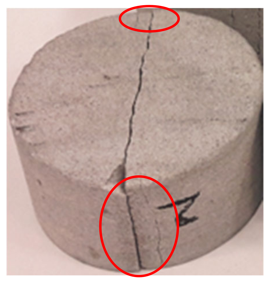
7. The Use of the Extension Strain Criterion to Evaluate the Fracture Initiation in a Sandstone Sample Subjected to Tension in the Brazilian Test

The possibility of using the extension strain criterion to assess fracture initiation (Stacey’s condition) was presented with reference to the results of the Brazilian test. The results of DIC analysis were used for this purpose (Figure 10a–c).
Since the Brazilian test was conducted in a servo-controlled testing machine under the control of constant horizontal displacements of the measuring base (Figure 1a), it was possible to determine the full pre- and post-failure path of the specimen (Figure 10d). Noteworthy are the extreme values of the extension strain εxx (positive values) and their location (Figure 10). At a low load level of about 0.63σT, in the central part of the disk in the direction of the load action, the highest values of these strains are concentrated around εxx = 1 × 10⁻³. Considering the load level, they are relatively high and exceed the fracture initiation criterion as proposed by Stacey (Table 3). It can be assumed that in the case of the sandstone under analysis, even before the tensile strength of the specimen was reached, the fracture initiation process had already begun. This is also indicated by the non-linear characteristics of the specimens in the Brazilian test (Figure 2a). For the load corresponding to tensile strength σT, the values of the determined deformations are higher than εxx = 3.5 × 10⁻³. Their extremum is not located in the centre of the sample but shifted towards the loading platens (Figure 10b). The extremum of deformations at this level of loading exceeds the values of Stacey’s criterion by many times, as confirmed by the fact that the first cracks had already been observed before the maximum load was reached. In the post-acting load phase (Figure 10c), deformations are determined based on the macro fracture.

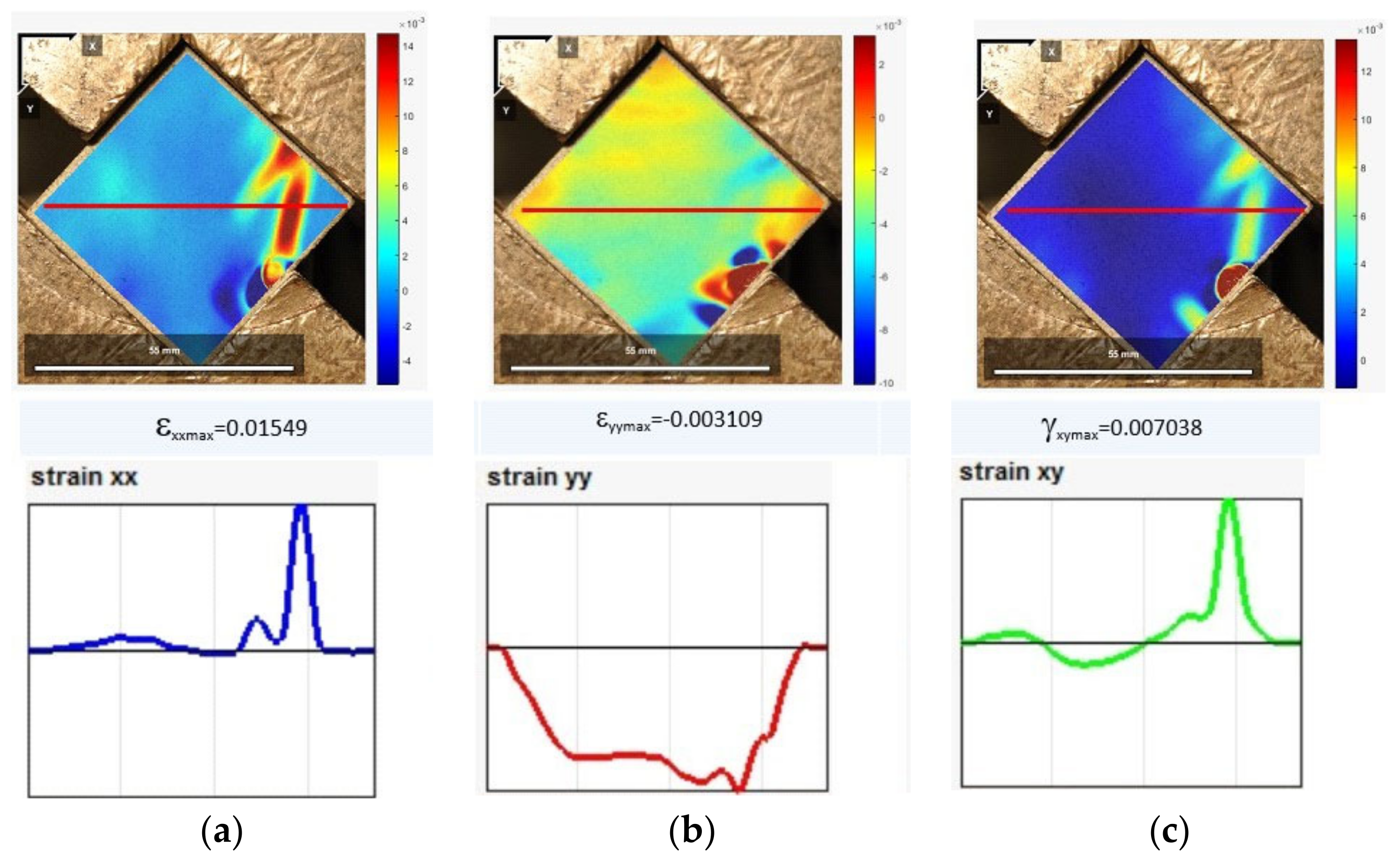
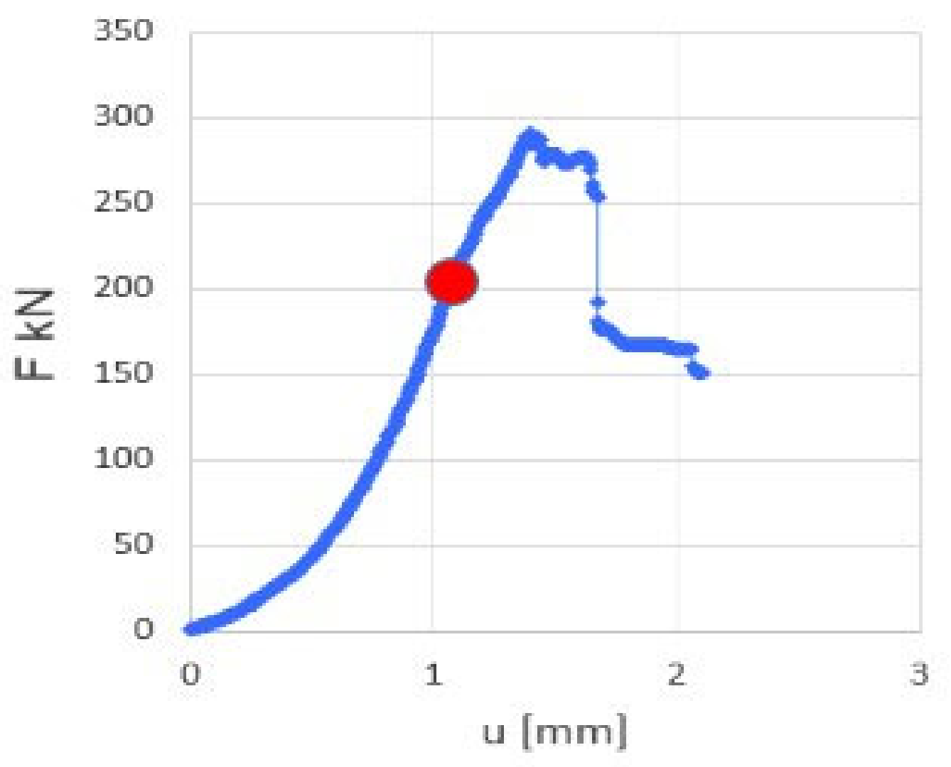
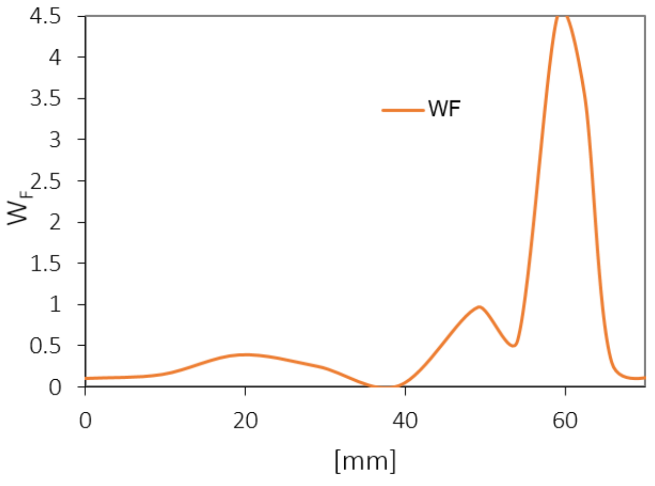
8. The Application of the Extension Strain Criterion to Evaluate the Microscopic Failure of a Rock Sample in the Simple Shear Test

The possibility of using the extension strain criterion was also presented to evaluate the macroscopic failure of a sandstone sample subjected to simple shear. In this case, Fujii’s extension strain criterion was used to evaluate the macroscopic strength of the rock sample.
The state of stress and strain in the sample in the simple shear test is complex, and its experimental evaluation is practically possible only with the aid of DIC. Figure 11 shows strain maps εxx, (Figure 11a) εyy (Figure 11b) and γxy (Figure 11c) on the front surface of a 50 mm × 50 mm × 50 mm cubic specimen, corresponding to a loading level of 0.7Fcrit (Figure 12).
In the complex deformation state, the maximum values of the extension strain should be determined as principal strains (Equation (9)).
ε 1 , 2 = ε x x + ε y y 2 ± ε x x ε y y 2 2 + γ x y 2 2
Based on the values of principal strains and laboratory-determined extension strains, εTC a simple strength condition can be defined based on Fujii’s criterion, using Equation (10). A value of WF > 1 indicates the failure of the rock.
W F = ε 2 ε T C
This condition enables determining the degree of rock failure in the selected section. As can be seen in Figure 11, due to the inaccurate placement of the specimen in the machine’s jaws, there is a concentration of deformations, locally in the right corner of the specimen. Despite the relatively low-loading level of 0.7Fcrit locally, the values of deformation reached high levels, accompanied by local failure (Figure 13), before reaching the critical destruction force of the whole sample. It should be noted that the destruction is local and does not affect the entire specimen.

9. Conclusions

This paper discusses the identification and use of the extension strain criterion for evaluating fracture initiation and its application as a macroscopic strength condition. Although the criterion, originally given by Stacey, deals with fracture initiation phenomena at the micro level, it has also acquired another form, namely the description of macroscopic failure of rock samples (Fujii’s criterion). Such a criterion in both forms then describes different phenomena, and thus the process of identification and evaluation of analysis results is different.
It should be noted that there are several ways to determine the extension strain criterion, and they will depend on the phenomena which the condition is intended to describe. According to Stacey, this can be done using the results of the UCS characteristics or the direct or Brazilian tensile strength test. If the extension strain criterion is treated as a strength condition (Fujii’s condition), the extension strain corresponding to the failure of the specimens should be determined based on the uniaxial and triaxial compression tests. It should be remembered that, for triaxial tests, there is a limit of confining pressure p, beyond which the extension strain is pressure dependent. This limit should be the subject of further analysis.
When determining the condition, one should exercise caution as different identification methods would yield different values for the extension strain criterion. It is, therefore, crucial to take into account the phenomena which the criterion is actually intended to be used for.
In determining the CI criterion in the Brazilian test, it seems important to take into account the occurrence of maximum extension strains outside the centre of the specimen, shifted in the direction of loading platens. Measurements performed with a strain gauge or with an extensometer at the centre do not cover the region of fracture-propagation initiation, and a DIC analysis may be helpful in such a case.
In general, it should be noted that the conditions and strength criteria expressed in strains have a greater spread of results than those expressed in non-strains. This is because the determination of strains in specimens is local, on a specific measurement basis, and it is not averaged across the specimen as is the case with stress values.

Funding

This research received no external funding.

Institutional Review Board Statement

Not applicable.

Informed Consent Statement

Not applicable.

Data Availability Statement

The data presented in this study are available on request from the corresponding author.

Conflicts of Interest

The author declares no conflicts of interest.

References

  1. Stacey, T.R. A simple extension strain criterion for fracture of brittle rock. Int. J. Rock Mech. Min. Sci. 1981, 18, 469–474. [Google Scholar] [CrossRef]
  2. Wesseloo, J.; Stacey, T.R. A Reconsideration of the Extension Strain Criterion for Fracture and Failure of Rock. Rock Mech. Rock Eng. 2016, 49, 4667–4679. [Google Scholar] [CrossRef]
  3. Barton, N.; Shen, B. Risk of shear failure and extensional failure around overstressed excavations in brittle rock. J. Rock Mech. Geotech. Eng. 2017, 9, 210–225. [Google Scholar] [CrossRef]
  4. Shen, B.; Barton, N. Rock fracturing mechanisms around underground openings. Geomech. Eng. 2018, 16, 35–47. [Google Scholar]
  5. Andersson, J.C.; Martin, C.D.; Stille, H. The Aspo Pillar Stability Experiment: Part II—Rock mass response to coupled excavation-induced and thermal induced stresses. Int. J. Rock Mech. Min. Sci. 2009, 46, 879–895. [Google Scholar] [CrossRef]
  6. Barton, N.; Shen, B. Extension failure mechanisms explain failure initiation in deep tunnels and critical heights of cliff faces and near-vertical mountain walls. In Proceedings of the 51st US Rock Mechanics Geomechanics Symposium, San Francisco, CA, USA, 25–28 June 2017. [Google Scholar]
  7. Martin, C.D.; Kaiser, P.K.; McCreath, D.R. Hoek–Brown parameters for predicting the depth of brittle failure around tunnels. Can. Geotech. J. 1999, 36, 136–151. [Google Scholar] [CrossRef]
  8. Diederichs, M.S. Rock fracture and collapse under low confinement conditions. Rock Mech. Rock Eng. 2003, 36, 339–381. [Google Scholar] [CrossRef]
  9. Diederichs, M.S.; Kaiser, P.K. Tensile strength and abutment relaxation as failure control mechanics in underground excavations. Int. J. Rock Mech. Min. Sci. 1999, 36, 69–96. [Google Scholar] [CrossRef]
  10. Diederichs, M.S.; Kaiser, P.K.; Eberhardt, E. Damage initiation and propagation in hard rock tunnelling and the influence of near-face stress rotation. Int. J. Rock Mech. Min. Sci. 2004, 41, 785–812. [Google Scholar] [CrossRef]
  11. Shen, B.; Khanal, M.; Shi, J.; Mallants, D. Modelling geomechanical stability of a large deep borehole in shale for radioactive waste disposal. Tunn. Undergr. Space Technol. 2024, 145, 105606. [Google Scholar] [CrossRef]
  12. Shi, J.; Shen, B.; Khanal, M.; Mallants, D. Analytical and Numerical Estimation of Fracture Initiation and Propagation Regions around Large-Diameter, Deep Boreholes for Disposal of Long-Lived Intermediate-LevelWaste. Energies 2022, 15, 2445. [Google Scholar] [CrossRef]
  13. Louchnikov, V. Simple calibration of the extension strain criterion for its use in numerical modelling. In Strategic versus Tactical Approaches in Mining 2011; Potvin, Y., Ed.; Australian Centre for Geomechanics: Perth, Australia, 2011; ISBN 978-0-9806154-6-3. [Google Scholar]
  14. Fujii, Y.; Kiyama, T.; Ishijima, Y.; Kodama, J. Examination of a Rock Failure Criterion Based on Circumferential Tensile Strain. Pure Appl. Geophys. 1998, 152, 551–577. [Google Scholar] [CrossRef]
  15. Kwaśniewski, M.; Takahashi, M. Strain-based failure criteria for rocks: State of the art and recent advances. In Proceedings of the ISRM International Symposium—EUROCK 2010, Lausanne, Switzerland, 15–18 June 2010; Taylor & Francis Group: London, UK, 2010. [Google Scholar]
  16. Staat, M. An Extension Strain Type Mohr–Coulomb Criterion. Rock Mech. Rock Eng. 2021, 54, 6207–6233. [Google Scholar] [CrossRef]
  17. Eberhardt, E.; Stead, D.; Stimpson, B.; Read, R.S. Identifying crack initiation and propagation thresholds in brittle rock. Can. Geotech. J. 1998, 35, 222–233. [Google Scholar] [CrossRef]
  18. Nicksiar, M.; Martin, C.D. Evaluation of Methods for Determining Crack Initiation in Compression Tests on Low-Porosity Rocks. Rock Mech. Rock Eng. 2012, 45, 607–617. [Google Scholar] [CrossRef]
  19. Brace, W.F.; Paulding, B.; Scholz, C. Dilatancy in the fracture of crystalline rocks. J. Geophys. Res. 1966, 71, 3939–3953. [Google Scholar] [CrossRef]
  20. Perras, M.A.; Diederichs, M.S. A Review of the Tensile Strength of Rock: Concepts and Testing. Geotech. Geol. Eng. 2014, 32, 525–546. [Google Scholar] [CrossRef]
  21. Li, D.Y.; Ngai, L.; Wong, Y. The Brazilian disc test for rock mechanics applications: Review and new insights. Rock Mech. Rock Eng. 2013, 46, 269–287. [Google Scholar] [CrossRef]
  22. ISRM. Suggested methods for determining tensile strength of rock materials. Int. J. Rock Mech. Min. Sci. Geomech. Abstr. 1978, 15, 99–103. [Google Scholar] [CrossRef]
  23. ASTM D2936-08; Standard Test Method for Direct Tensile Strength of Intact Rock Core Specimens. ASTM International: West Conshohocken, PA, USA, 2008.
  24. Blaber, J.; Adair, B.; Antoniou, A. Ncorr: Open-source 2D digital image correlation Matlab software. Exp. Mech. 2015, 55, 1105–1122. [Google Scholar] [CrossRef]
  25. Diederichs, M.S. The 2003 Canadian Geotechnical Colloquium: Mechanistic interpretation and practical application of damage and spalling prediction criteria for deep tunnelling. Can. Geotech. J. 2007, 44, 1082–1116. [Google Scholar] [CrossRef]
  26. Diederichs, M.S.; Martin, C.D. Measurement of spalling parameters from laboratory testing. In Proceedings of the ISRM International Symposium—EUROCK 2010, Lausanne, Switzerland, 15–18 June 2010. [Google Scholar]
  27. Hondros, G. The evaluation of Poisson’s ratio and the modulus of materials of a low tensile resistance by the Brazilian (indirect tensile) test with particular reference to concrete. Aust. J. Appl. Sci. 1959, 10, 243–268. [Google Scholar]
  28. Fairhurst, C. On the validity of the ‘Brazilian’ test for brittle materials. Int. J. Rock Mech. Min. Sci. Geomech. Abstr. 1964, 1, 535–546. [Google Scholar] [CrossRef]
  29. Hudson, J.A.; Brown, E.T.; Rummel, F. The controlled failure of rock discs and rings loaded in diametral compression. Int. J. Rock Mech. Min. Sci. Geomech. Abstr. 1972, 9, 241–248. [Google Scholar] [CrossRef]
  30. Li, X.; Takahashi, M.; Wu, Z.; Xu, D. An experimental study on the failure criteria based on strain. Hokkaido Geotech. 1999, 87–93. (In Japanese) [Google Scholar]
Figure 1. Experimental setup: (a) the Brazilian test, (b) the unconfined compression test, (c) the MTS confined compression test, and (d) the loading scheme in the triaxial compression test.
Applsci 14 08953 g001
Figure 2. The experimental setup—a high-resolution camera for (a) the Brazilian test, (b) the simple shear sandstone samples tests, and (c) an extensometer and DIC comparison analysis.
Applsci 14 08953 g002
Figure 3. Rock block 0.5 m × 0.5 m × 0.5 taken from a Lubon tunnel (a) and longitudinal wave velocity histogram (b). Sandstone sample characteristics according to (c) the Brazilian test, (d) the unconfined compression test, and (e) the triaxial compression test.
Applsci 14 08953 g003aApplsci 14 08953 g003b
Figure 4. Dependence of the radial strain (extension strain) on the axial strain in the UCS tests of sandstone.
Applsci 14 08953 g004
Figure 5. The CI threshold determined for a sandstone sample p_j_3 using the methods of (a) crack volumetric strain, and (b) volumetric strain and the lateral strain–axial stress relationship.
Applsci 14 08953 g005
Figure 6. The extension strain criterion values corresponding to the CI threshold (a) strain values, (b) and corresponding stress values.
Applsci 14 08953 g006
Figure 7. Compressive strength and CI thresholds for all test confining pressures.
Applsci 14 08953 g007
Figure 8. Shear failure and fractures as stress concentration in the sample near the loading platen.
Applsci 14 08953 g008
Figure 9. The extension strain criterion values (a) schematically based on the radial strain plots of the specimens in the UCS test or (b) resulting from the Brazilian, UCS, and triaxial compression tests.
Applsci 14 08953 g009
Figure 10. Maps of the horizontal strain on the surface of a rock disk in the Brazilian test at three loading levels, i.e., (a) 0.63σT, (b) σT, and (c) in the post-failure loading phase, and (d) characteristics of the Brazilian test.
Applsci 14 08953 g010
Figure 11. Strain maps (a) εxx, (b) εyy, and (c) γxy, of the sheared specimen at a loading level of 0.7Fcrit.
Applsci 14 08953 g011
Figure 12. Characteristics of vertical displacement of the piston of the testing machine in the straight shear test of sandstone at load level of 0.7Fcrit. (red circle).
Applsci 14 08953 g012
Figure 13. The failure level in the simple shear test of the sandstone sample, according to the criterion proposed by Fujii et al. [14].
Applsci 14 08953 g013
Table 1. Summary results of the uniaxial and triaxial compression tests and the Brazilian test.
CopressionTension
SamlpeConf. σ2 = σ3DensityLong. Wave Vel.σ1ε1cεTcE v SampleDensityLong. Wave Vel.σTεTc
MPakg/m3m/sMPa[-][-]GPa[-] kg/m3m/sMPa[–]
p_j_1-2320.82565.871.150.0049−0.004116.330.35p_r_12270.662373.744.64−0.0026
p_j_2-2351.62511.165.680.0033−0.003014.300.33p_r_22378.142474.924.74−0.0026
p_j_3-2338.42468.476.300.0054−0.003416.920.24p_r_32289.072692.315.27−0.0028
p_j_4-2337.02555.671.530.0058−0.003715.400.26p_r_42266.472864.724.26−0.0021
p_j_5-2278.42543.362.500.0059−0.003613.030.21p_r_52344.972472.604.80−0.0028
Average 2325.2 69.40.0051-0.003615.20.3 2309.92575.74.7−0.0026
Stand. dev. 25.4 4.80.00090.00041.40.1 44.2178.20.30.0002
p_t_12.52327.12611.8474.540.0099−0.00509.100.20
p_t_252298.12569.4491.100.0082−0.004712.680.26
p_t_352312.32392.64115.000.0065−0.003625.380.20
p_t_4102321.22516.13158.500.0098−0.003923.160.28
p_t_5102287.82363.64161.170.0073−0.005526.240.30
p_t_6152293.42392.64176.210.0072−0.004729.790.25
p_t_7152334.92600172.070.0094−0.005823.430.27
Average 2310.72507.5
Stand. dev. 16.799.2
Table 2. The CI and extension strain criterion values determined using different UCS methods.
SampleLateral StrainDiltancy MethodCrack Volumetric StrainPoisson’s Ratio
εext []CI [MPa]εext []CI [MPa]εext []CI [MPa]εext []CI [MPa]
p_j_1−0.00020713.84−0.0000638.28−0.00027117.99−0.00022815.00
p_j_2−0.00017416.10−0.0000929.52−0.00025017.53−0.00014113.36
p_j_3−0.00020417.99−0.0000819.18−0.00021819.06−0.00016014.97
p_j_4−0.00009111.83−0.0000397.39−0.00016916.21−0.00009912.09
p_j_5−0.00009512.36−0.0000799.85−0.00020416.89−0.00010312.94
Average−0.00015414.42−0.0000718.85−0.00022217.54−0.00014613.67
Stand. dev.0.0000512.320.0000180.890.0000350.970.0000471.15
Table 3. The tensile strength σT and extension strain criterion values εext corresponding to Stacey’s criterion obtained for Brazilian tests.
SampleσTεext
MPa[–]
p_r_14.640.00058
p_r_24.740.00059
p_r_35.270.00066
p_r_44.260.00053
p_r_54.800.00060
Average4.740.00059
St. Dev.0.320.00004
Disclaimer/Publisher’s Note: The statements, opinions and data contained in all publications are solely those of the individual author(s) and contributor(s) and not of MDPI and/or the editor(s). MDPI and/or the editor(s) disclaim responsibility for any injury to people or property resulting from any ideas, methods, instructions or products referred to in the content.

