Article

Numerical and Experimental Studies on Crack Resistance of Ultra-High-Performance Concrete Decorative Panels for Bridges

1
College of Civil Engineering, Hunan University, Changsha 410082, China
2
Department of Civil Engineering, The University of Tokyo, Tokyo 113-8656, Japan
*
Author to whom correspondence should be addressed.
Appl. Sci. 2024, 14(2), 636; https://doi.org/10.3390/app14020636
Submission received: 27 December 2023 / Revised: 8 January 2024 / Accepted: 8 January 2024 / Published: 11 January 2024

Abstract

:
This study develops a new type of decorative bridge panel by ultra-high-performance concrete (UHPC) based on the project of the Guangyangwan Bridge. First, the numerical analysis was carried out using MIDAS and ABAQUS to find the critical position of the bridge and decorative panels. The numerical results showed that the last concrete cantilever segment had the greatest vertical deflection, and the corresponding panel had the greatest stress response. Based on the numerical results, this study conducted a series of full-scale, self-balanced bending tests to examine the crack resistance of six UHPC panels and six glass fiber-reinforced concrete (GRC) panels with varying curved section thicknesses (from 25 to 40 mm). The experimental results indicate that, due to the high strength of the UHPC matrix and the wall effect of steel fiber distribution, the crack resistance of UHPC panels is significantly superior to that of GRC panels. UHPC panels possessed superior stiffness and ductility, while GRC panels showed brittle fracture when the curved section thickness reached 34 mm. The uniaxial tensile cracking strength of UHPC with a steel fiber volume fraction of 1.6% was 14.7% greater than that of GRC with a glass fiber volume fraction of 5%. At the same curved section thicknesses, UHPC decorative panels exhibit cracking loads and ultimate loads that are 64.3% to 123.0% and 29.2% to 115.0% greater than GRC panels, respectively. Hence, UHPC is more suitable to produce ultra-thin decorative panels for bridges that are subjected to severe environmental action and external forces.

1. Introduction

With significant advancements in science and technology, the mechanical performance of bridges now can satisfy a wide range of practical applications. As a result, more attention is paid to the aesthetic aspects of bridges [1]. However, the pursuit of innovative bridge aesthetics through structural design poses considerable challenges for designers and construction practices. In addressing this, decorative panels emerge as an effective solution, as they introduce novel aesthetics without imposing a substantial increase in self-weight or an adverse impact on the mechanical performance of bridges.
Glass fiber-reinforced cement (GRC), a commonly used decorative material in civil engineering, boasts excellent mechanical properties and low self-weight. Nevertheless, over extended periods of use, the glass fiber is susceptible to reactions with alkaline substances, leading to a decline in tensile strength and durability [2]. In contrast, ultra-high-performance concrete (UHPC) is an alternative with high strength, high toughness, and high durability [3,4]. UHPC exhibits remarkable compressive strength (>100 MPa), tensile strength (8–15 MPa), and toughness, surpassing those of GRC by a significant margin [5,6,7,8]. Additionally, the distribution of steel fibers in UHPC transitions from a 2-dimensional to a 3-dimensional configuration due to the wall effect, enhancing the constraint effect of steel fibers on the cementitious matrix [9]. This attribute is particularly beneficial for thin decorative panels. Moreover, UHPC possesses a “self-healing” property. The steel fibers interlacedly distribute within the UHPC crack, which can close the UHPC crack when the tensile stress decreases due to the elastic retraction of steel fibers [10]. Additionally, the water-to-cement ratio of UHPC is very low, indicating that there is more cement in the unit volume of UHPC. Once the micro-crack emerges, the unhydrated cement can react with water in the ambient environment and produce hydrates to fill the UHPC micro-crack [11]. Therefore, UHPC can extend the service life of structures and reduce maintenance costs. Furthermore, UHPC, after high-temperature steam curing, experiences minimal long-term shrinkage and creep during its service life [12,13]. Consequently, compared with GRC, UHPC is a more suitable choice for decorative panels, especially those demanding superior mechanical properties and durability.
Recent global applications of UHPC in fabricating façade decorative elements for buildings include the curtain wall of the Museum of European and Mediterranean Cultures in Marseille Saint-Jean Port, Marseille, France, the shaped concrete façade of the Italian National Pavilion at the Milan Expo 2015, and the curtain wall of the exhibition center of Yue Cai City in Shenzhen [14]. Research on ultra-high-performance concrete (UHPC) façade panels extends beyond practical applications. Kim et al. [15] investigated the impact resistance of differently colored UHPC façade panels, revealing their ductility and exceptional impact resistance. Harsono et al. [16] explored the integration of digital technologies in supporting the project delivery process for building facades using prefabricated UHPC panels. Mueller et al. [17] compared reactive powder concrete (RPC) façade panels with various inner reinforcement materials ranging from steel fibers (UHPC) to fiber textile grids, establishing a sustainable approach for RPC in thin-façade elements. Additionally, Maier et al. [18] introduced a mineralized foam (MF)-modified UHPC showcasing a blend of robust bearing capacity and insulation properties. Applications and research underscore the significant application potential of UHPC in the structural decoration field. However, the service environment of bridges is more challenging than that of buildings, and their structures and load types are also different. Hence, decorative elements for bridges demand more robust mechanical properties and durability.
Based on the Chongqing Guangyangwan Bridge project, this study developed a UHPC decorative panel scheme for this bridge. The stress responses of the UHPC decorative panel were obtained through numerical analysis. Additionally, experimental studies were carried out to compare the crack resistance of GRC and UHPC panels with varying thicknesses in their curved sections. The research results may provide insights and references for the theoretical study and project design of UHPC decorative panels.

2. Design and Analysis of Decorative Panels

The Chongqing Guangyangwan Bridge is a steel-concrete hybrid rigid-frame bridge with spans of 30 m + 55 m + 110 m + 255 m + 100 m = 550 m. To harmonize the bridge with the ecological surroundings of Guangyang Island, the bridge’s aesthetics have been enhanced through the application of external decorative panels. These decorative panels serve to visually reconfigure the bridge, creating the optical illusion of a slenderer girder and making the bridge more visually appealing. UHPC decorative panels are affixed to the sides of the box girder and are designed to bear a variety of loads, including self-weight, wind forces, temperature effects, and the induced deformations of the main girders. The decorative lines on the Guanyangwan Bridge are depicted in Figure 1.

2.1. Configuration of Decorative Panels

In the Guangyangwan Bridge, the concrete piers and main girders are cast in situ, and the main girders are cast using the balanced cantilever. The decorative panels are constructed by cantilever after 7 days of curing of the corresponding concrete cantilever segment. The steel girders are prefabricated in factories and then installed by lifting devices. The dimensions of the decorative panels vary uniformly according to the depth of the main girders. The panels are of the largest size at the bridge pier, with a height of approximately 1.9 m, and they are of the smallest size at the position of the last concrete cantilever segment and the steel girder, with a height of about 51 cm. Each individual panel is of varying length, from approximately 3 m to 4 m, which is equal to the length of the concrete cantilever segment. According to the lengths of the panels, the number of connections is 2 or 3.
Figure 2 shows the dimension and configuration of the UHPC decorative panel at the position of the last concrete cantilever segment and the steel girder. The curved section of the UHPC decorative panel is prone to cracking during the construction and service periods. Thus, it is necessary to locally thicken this section to enhance the overall crack resistance of the panel. The panels are connected to the main girders through frictional energy-dissipating connections formed by bolts, shear keys, and embedded steel plates. When the external load is less than the maximum static friction force, the connection between the main girders and the panels can be considered a “rigid connection”. When the external load exceeds the maximum static friction force, the deformation of the connection allows the panels to be capable of adapting to the deformations of the main structure. This limits the increase in the load transferred to the panels, preventing considerable damage to the panels. At this point, the connection can be considered a “flexible connection” [19,20]. This approach helps in eliminating temperature-induced stresses and accommodating the deformations of the main girders.
This kind of construction approach allows for the subsequent construction of the decorative panel after completing the concrete cantilever segment, thereby saving on the overall construction timeline. However, it’s important to note that the embedded steel plate was positioned at a designated location during the concrete casting process, and the shear key was subsequently welded onto the steel plates. This procedure requires careful consideration of the welding temperature to prevent significant temperature gradients that could lead to concrete cracking.

2.2. Structural Analysis

2.2.1. Analysis of the Entire Bridge

Before the design of crack resistance experiments, the most adverse position of the UHPC decorative panel under external loads should be determined. A numerical model of the entire bridge was first developed using MIDAS/CIVIL 2021, a finite element analysis (FEA) software in civil engineering, to achieve the structural response of the entire bridge, as depicted in Figure 3. Beam elements were utilized to simulate the main girders and piers of the bridge. The ordinary concrete and steel used in the bridge include the C60 concrete, HRB400 and HPB300 steel bars, Φ15.2 mm steel strands, and Q345 steel plates. All materials are provided by Hunan Zhonglu Huacheng Bridge Technology Co. (Xiangtan, China) and met the requirements of JTG 3362-2018 [21]. Therefore, the design values of the mechanical properties of the concrete and steel in this bridge were adopted in simulation, as shown in Table 1.
The bridge was subjected to various loads, including the self-weight, vehicle load, temperature effects, shrinkage and creep of concrete, and support settlement, which are likely to cause cracking to the decorative panels. The loads were applied to the bridge with respect to the combination method for the normal service state provided by JTG 3362-2018 [21]. The values of dead loads, temperature, and vehicle load were determined according to JTG D60-2015 [22], GB55001-2021 [23], and CJJ11-2011 [24], respectively. The types and values of various loads and their combination coefficients are listed in Table 2 and Table 3.
The deflection of the segment at the top of the pier, the last concrete cantilever segment, and the midspan of the steel girder were selected for analysis. During analysis, the whole stress history, including the construction stage and service stage, was considered. The numerical results of the deflection for these three key segments are presented in Table 4. The vertical deflection in the last concrete cantilever segment was significantly larger than that in other segments, leading to the most extreme damage to the decorative panels. Therefore, the decorative panel at the last concrete cantilever segment was selected for further analysis and experimental investigation.

2.2.2. Analysis of Decorative Panels

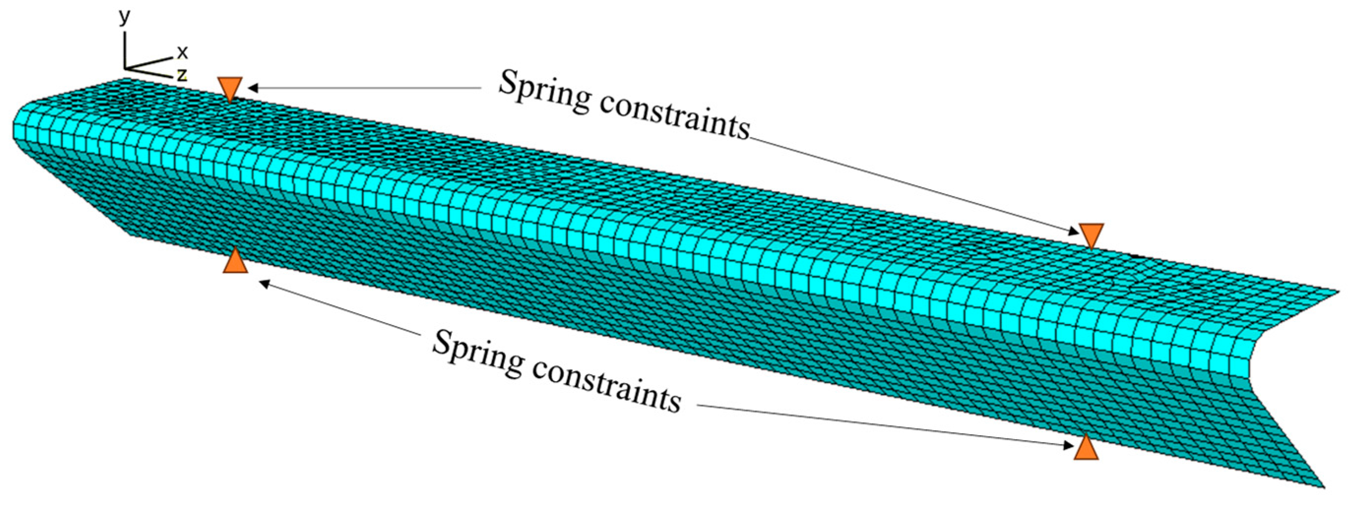
Before self-bending tests, a full-scale 3D numerical model of the decorative panel in the last concrete cantilever segment was developed using ABAQUS 2018, as shown in Figure 4. In this model, the panels were simulated using shell elements. Since the primary objective of this simulation was to identify the position with the highest stress response for subsequent crack resistance testing, the panel material in ABAQUS was assumed to be elastic. The modulus of elasticity and expansion factor of shell elements were set at 40 GPa (UHPC) and 1 × 10⁻⁵, respectively. The frictional energy-dissipating connections between the main girders and panels were simulated using non-linear spring elements. The vertical degrees of freedom of these connections were constrained. The deformation parameters of frictional energy-dissipating connections were determined via a full-scale push-out test. The load vs. relative displacement in the shear direction of the connection is shown in Figure 5. The maximum static frictional force and ultimate shear force are 7.475 kN and 84.900 kN, respectively.
Subsequently, the individual and combined load actions were applied to the panel model to obtain the stress responses. These loads included the forced deformation induced by the main girder, wind loads, self-weight, and temperature effects. The values and types of the loads as well as the stress responses are presented in Table 5. The wind load on the decorative panels was determined by referring to GB50009-2012 [25]. The forced deformation value was equal to the vertical deformation of the last concrete cantilever in Table 4. Other load values were determined by the same standards as before.
As shown in Table 5, the tensile stresses individually induced by the self-weight, wind load, and temperature were relatively smaller than those induced by the forced deformation because the deformation caused by the bridge was considerable and led to the greatest tensile stress in the panel. The stress patterns of the panel model in two directions are shown in Figure 6. It can be identified that the curved section and connection position saw the greatest tensile stress. However, the connection position was always thickened locally in practical engineering, resulting in smaller tensile stress. Thus, the stress of the curved section was investigated in this study.

3. Self-Balanced Bending Tests of Decorative Panels

3.1. Test Design

As shown in Table 5, the maximum tensile stresses of decorative panels always emerge at the curved section. Therefore, in this study, the crack resistance of curved sections of decorative panels was investigated experimentally. The thickness of the curved section was selected as the research parameter due to its great impact on the crack resistance of the decorative panel. To examine crack resistance disparities between GRC and UHPC decorative panels, a total of six UHPC and six GRC full-scale decorative panels were manufactured. The panel specimens have a length of 500 mm and a height of 510 mm, which are the same as those decorative panels at the last cantilever concrete segment, as shown in Figure 7. Their straight sections have a constant thickness of 25 mm, and curved sections have varying thicknesses. The specimen number and the experimental parameters of the specimens are listed in Table 6.

3.2. Mechanical Property Tests of Concrete

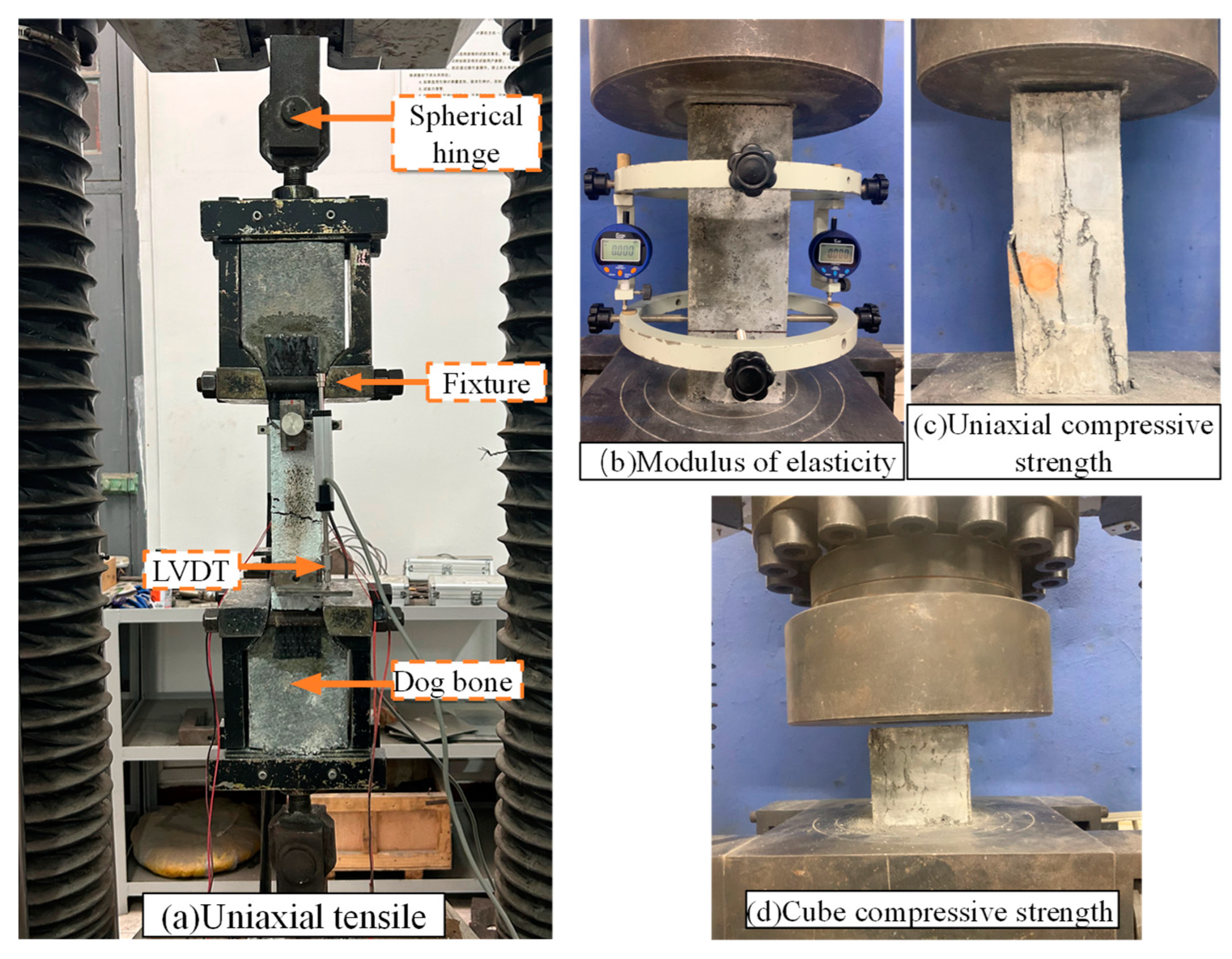
The GRC was supplied by Guangdong Xinshang Art Co., Ltd. (Guangzhou, China), which employed P.W-1 52.5 Portland cement and glass fibers with a length of 30 mm and a volume fraction of 5%. The UHPC was provided by Hunan Renjian Concrete Co., Ltd. (Changsha, China), of which the components included 42.5 R Portland cement and short straight steel fibers with a length of 9 mm and a fiber volume fraction of 1.6%. The UHPC decorative panels underwent high-temperature steam curing at 90 °C for 48 h after casting, while GRC decorative panels were naturally cured for 28 days. The specimens for mechanical property tests were cast simultaneously and cured under the same conditions as the panel specimens. The mechanical properties of GRC and UHPC, including cube compressive strength, uniaxial compressive and tensile strength, and modulus of elasticity, were tested according to GB/T 31387-2015 [26] and ASTM C1116/C1116M-23 [27]. The cube compressive strength test utilized cube specimens with a size of 100 × 100 × 100 mm3, while the tests for uniaxial compressive strength and modulus of elasticity both employed prism specimens with a size of 100 × 100 × 300 mm3. The loading rate for compression tests was set at 1.2 MPa/s. The uniaxial tensile strength of concrete was determined through uniaxial tensile tests conducted on dog-bone-shaped tension specimens. The tension specimens had a cross-sectional dimension of 100 × 50 mm2, with a gauge length of 200 mm. The MTS 60 t universal testing machine was used to load, with a loading rate of 10 N/s. The mechanical property tests of the concrete are shown in Figure 8. Each mechanical property test included three specimens, and the maximum relative error between specimens did not exceed 15% in one test. The mechanical properties of GRC and UHPC are presented in Table 7.

3.3. Test Setup and Apparatus of Self-Bending Tests

The external load was applied using a hydraulic jack with a capacity of 100 kN, and the load value was recorded by a load cell with a scale of 5 kN. The test loading procedure is illustrated in Figure 9a. The jack was positioned between the two straight sections of the panel specimen. With partial reference to the U.S. standard ASTM C1550-2020 [28], the curved section was designed to undergo a self-balancing bending test. This test aims to induce tensile cracking on the inner side, mimicking the crack pattern observed in similar decorative panels during service. Three dial gauges were set up at the top of the straight section of the decorative panel to measure the deflection of the panel. The loading block was cast simultaneously with the panel specimen, and it was used solely for loading without impact on the flexural behavior of the curved section.

4. Test Results and Discussion

4.1. Failure Mode

At the beginning of loading, all panel specimens performed elastically, with no concrete cracking. After the concrete cracked, the panel specimens entered a nonlinear deformation stage, with the continuous development of multiple cracks at the inner side of the curved section, as shown in the red marks in Figure 10a. Upon reaching the ultimate bearing capacity, a principal crack penetrated the cross-section of the curved section, as depicted by the red marks in Figure 10b, signaling the failure stage. Subsequently, fibers began to pull out from the concrete (UHPC) or rupture (GRC), causing a consecutive decrease in bearing capacity.
Figure 10c–f, respectively, show the failure modes of UHPC and GRC panel specimens, as well as the tension specimens. It is evident that steel fibers or glass fibers were interlaced within the cracks, constraining the concrete cracks. The failure mode of UHPC panel specimens was consistent with that of UHPC tension specimens (Figure 10c,e), namely, both were steel fibers pulling out from the concrete. As shown in Figure 10f, in the cracks of GRC tension specimens, glass fibers were densely distributed and ruptured when the ultimate load was reached. However, the failure mode of GRC panels primarily involved the detachment of the glass fibers from the concrete, with only a small portion of glass fibers rupturing, as shown in Figure 10d. Furthermore, due to the larger volume fraction and greater length of glass fibers, quite a few glass fibers were distributed in the thickness direction of the panel, making it easier to detach at the curved section.

4.2. Load vs. Displacement

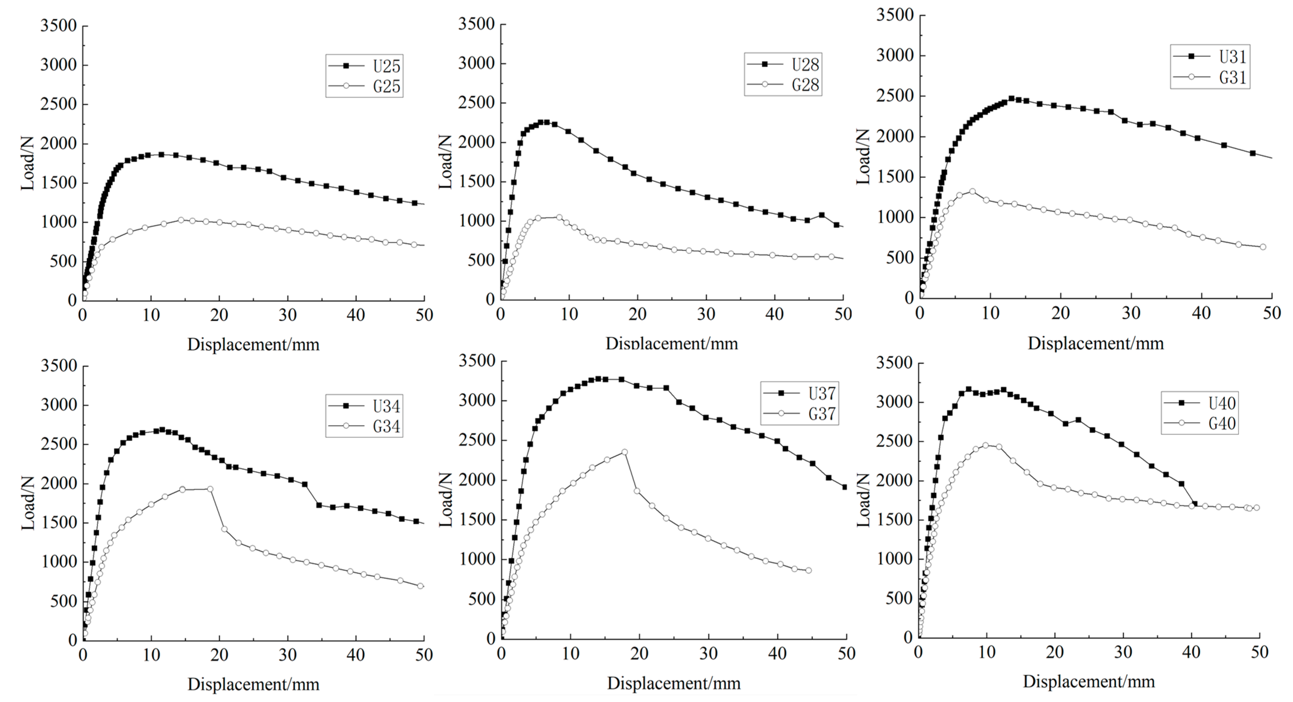
Figure 11 displays the load-displacement curves of the UHPC and GRC panel specimens with varying curved section thicknesses.
As shown in Figure 11, the six sets of curves exhibited a similar overall trend. At the beginning, the displacement grew proportionally to the test load. After concrete cracking, the curves transitioned from the linear stage to the nonlinear stage. The load-displacement curves deviated from a straight line, and the stiffness of panel specimens decreased. After reaching the ultimate load, the test load decreased with the consecutive increase in displacement. The bearing capacity of all UHPC panel specimens decreased gradually after the peak point, indicating their superior ductility. In contrast, when the curved section thicknesses exceeded 34 mm, the GRC panels saw a brittle failure with a rapid decrease in load after the peak point. This is because the delamination effect of glass fibers became more evident as the curved section thickness increased, leading to the detachment of a thin GRC laminate in the panel specimen. At the same curved section thicknesses, the UHPC panel specimens exhibited longer linear stages and greater slopes in their load-displacement curves than the GRC panel specimens. Furthermore, the ultimate loads of the UHPC panels were always greater than those of the GRC panels. This can be attributed to the higher matrix strength, greater modulus of elasticity, and better distribution of short steel fibers.

4.3. Characteristic Loads

4.3.1. Cracking Stress

In the test, the characteristic loads were recorded, and the equivalent cracking stress was calculated using Equation (1). The characteristic loads and cracking stress of the panel specimens are presented in Table 8.
σ c r = M W + P A
where M is the bending moment at the center of the curved section, M = P · L  P is the cracking load of the specimen, L is the length of the moment arm equal to the distance from the center of the loading cell to the center of the cracked section. L is measured during the test. W is the section modulus, W = b h 2 / 6 , b and h are the length and thickness of the curved section, respectively; A is the sectional area of the curved section; and P is the test load.
As shown in Table 8, the mean cracking stress of UHPC panel specimens was 8.12 MPa, slightly greater than that of UHPC tension specimens (7.8 MPa). It indicates that the UHPC can maintain its crack resistance well in this kind of thin panel. In contrast, the mean cracking stress of GRC panel specimens was 4.51 MPa, 33.7% lower than that of GRC tension specimens (6.8 MPa) because the reinforcement effect of glass fibers on the cement matrix was not effective in thin elements, resulting in a lower cracking stress. It can be concluded that UHPC is more suitable for producing ultra-thin and irregular components than GRC. The cracking stress and ultimate load of UHPC panels were higher than those of GRC panels by 64.3% to 123.0% and 29.2% to 115.0% at the same curved section thicknesses, respectively. It indicates that the replacement of GRC with UHPC is capable of improving both the crack resistance and bearing capacity of decorative panels.

4.3.2. Impact of Curved Section Thickness

Figure 12 illustrates the cracking stresses of all panel specimens. As shown in Figure 12, the cracking stresses of UHPC panel specimens decreased from 9.35 MPa to 7.42 MPa as the curved section thickness increased from 25 mm to 40 mm. This phenomenon is attributed to the wall effect of steel fiber distribution in UHPC; namely, the fibers near the concrete surface were basically distributed two-dimensionally, while they were distributed three-dimensionally within the thicker cross-section [29]. The parallel orientation of fibers with the tensile stress can significantly improve the tensile resistance of UHPC, increasing the utilization efficiency of steel fiber’s tensile strength. Additionally, the reinforcing effect of the fibers on concrete strongly depends on the orientation and distribution of fibers [30]. Therefore, as the curved section thickness decreases, more steel fibers are aligned with the direction of tensile stress in the curved section, leading to an increase in the cracking stresses of the UHPC panel specimens. However, the glass fiber had a length of 30 mm, which was like the thickness of the curved section. It resulted in no reorientation of glass fibers and, thus, consistent cracking stress in GRC panel specimens.
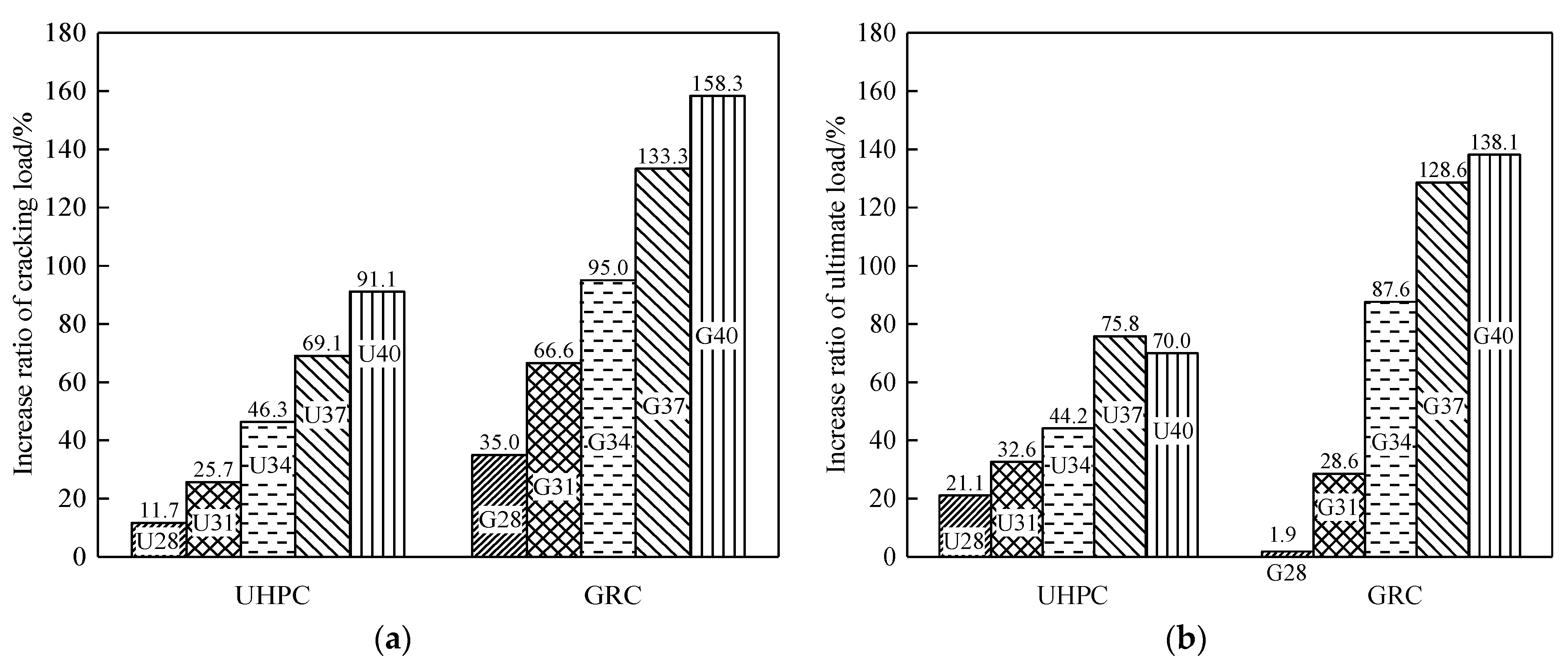
Figure 13 shows the increased ratio of panel specimens with varying curved section thicknesses. As shown in Figure 13a, the cracking loads of UHPC and GRC panel specimens significantly increased as the curved section thickness increased. Every 3 mm increase in the curved section thickness resulted in approximately 18.2% and 31.7% increases in cracking loads of UHPC and GRC panel specimens, respectively. The increases in cracking loads of UHPC and GRC panel specimens were stable due to the crack stress.
As illustrated by Figure 13b, before the curved section thickness reached 40 mm, the ultimate load of UHPC and GRC panel specimens, respectively, increased by 14.0% and 27.6% with every 3 mm increase in the curved section thickness. For the UHPC panel specimens, there was a small decrease in ultimate load after the thickness reached 40 mm. It might be attributed to the fact that more steel fibers were aligned in the non-parallel direction of the panel surface, leading to insufficient utilization of the tensile strength of the steel fibers and, therefore, the lower ultimate load of U40. Moreover, the most efficient curved section thickness for both UHPC and GRC panel specimens was 37 mm in this study, as U37 had the greatest ultimate load among UHPC panels, and the ultimate load of G37 was slightly smaller than that of G40 by 7%. Therefore, it can be concluded that there was an upper limit in the thickness of the curved section, and the influence of fiber distribution and wall effects need to be carefully considered in the design.

5. Conclusions

This study proposes a scheme for the UHPC decorative panel for bridges. Based on practical engineering, full-scale numerical analyses were carried out on the entire bridge and a single decorative panel. To reveal the difference in the crack resistance between UHPC and GRC decorative panels, twelve full-scale panel specimens were manufactured and subjected to bending tests. Some principal conclusions were drawn.
(1)
The numerical results show that the deformation of the main girder of the bridge was the primary cause of stress in the decorative panels. The curved section of the decorative panel had the greatest tensile stress, which should be paid particular attention in the design.
(2)
The failure modes of UHPC decorative panels and UHPC tension specimens were the pull-out of steel fibers from the UHPC matrix. The GRC tension specimens exhibited a failure mode of glass fiber rupture, while in the case of GRC decorative panels, the delamination of glass fibers tended to be the failure mode.
(3)
Compared to GRC decorative panels, UHPC decorative panels had greater stiffness and superior ductility. GRC decorative panels showed a brittle fracture after the curved section thickness reached 34 mm, while all the UHPC decorative panels saw ductile failure.
(4)
The cracking stresses of the UHPC decorative panels were like those of the UHPC tension specimens, while the GRC decorative panels exhibited a smaller cracking stress than the GRC tension specimens. The cracking load and ultimate load of the UHPC decorative panels exceeded those of the GRC decorative panels by 64.3% to 123.0% and 29.2% to 115.0%, respectively. Compared to 30 mm-long glass fibers, 9 mm-long steel fibers exhibit a more significant improvement in the crack resistance of the decorative panels.
(5)
The distribution of steel fibers in the panel shows a considerable size effect. In UHPC decorative panels, the cracking stress decreased slightly as the panel thickness increased. Due to fiber distribution, when the curved section thickness reached a threshold value (37 mm in this study), the value and increment of the ultimate load of UHPC decorative panels began to decrease.

Author Contributions

Conceptualization, Y.Z.; Methodology, Y.Z.; Validation, Y.Q.; Formal analysis, J.Z.; Investigation, J.Z.; Data curation, J.Z. and Y.Q.; Writing—original draft, J.Z.; Writing—review & editing, Y.Q.; Supervision, Y.Z.; Funding acquisition, Y.Z. All authors have read and agreed to the published version of the manuscript.

Funding

This study was financially supported by the Hunan Zhonglu Huacheng Bridge Technology Corporation with project number of H202291370751.

Institutional Review Board Statement

Not applicable.

Informed Consent Statement

Not applicable.

Data Availability Statement

The data presented in this study are available on request from the corresponding author. The data are not publicly available due to the authors’ future research work is strongly based on this.

Acknowledgments

We express our gratitude to Man Yu from Hunan Zhonglu Huacheng Bridge Technology Corporation (Xiangtan, China) and Lei Li from Lin International Engineering Consulting Corporation (Chongqing, China) for their help in designing and conducting the experiments.

Conflicts of Interest

The authors declare that this study received funding from Hunan Zhonglu Huacheng Bridge Technology Corporation. The funder had the following involvement with the study: material collection and specimen manufacturing.

References

  1. Liu, L. Study on the Selection of Bridge Form Based on Environment and Function. Master’s Thesis, Chongqing Jiaotong University, Chongqing, China, 2019. (In Chinese). [Google Scholar] [CrossRef]
  2. Branco, F.; Ferreira, J.; Brito, J.D.; Santos, J.R. Building structures with GRC. In Proceedings of the CIB World Building Congress, Wellington, New Zealand, 23–25 April 2003. [Google Scholar]
  3. Li, J.; Wu, Z.; Shi, C.; Yuan, Q.; Zhang, Z. Durability of ultra-high performance concrete—A review. Constr. Build. Mater. 2020, 255, 119296. [Google Scholar] [CrossRef]
  4. Xue, J.; Briseghella, B.; Huang, F.; Nuti, C.; Tabatabai, H.; Chen, B. Review of ultra-high performance concrete and its application in bridge engineering. Constr. Build. Mater. 2020, 260, 119844. [Google Scholar] [CrossRef]
  5. Abbas, S.; Nehdi, M.L.; Saleem, M.A. Ultra-High Performance Concrete: Mechanical Performance, Durability, Sustainability and Implementation Challenges. Int. J. Concr. Struct. Mater. 2016, 10, 271–295. [Google Scholar] [CrossRef]
  6. Graybeal, B.A. Material Property Characterization of Ultrahigh Performance Concrete. Mclean: Federal Highway Administration. 2006. Available online: https://rosap.ntl.bts.gov/view/dot/38714/dot_38714_DS1.pdf (accessed on 17 December 2023).
  7. Shafieifar, M.; Farzad, M.; Azizinamini, A. Experimental and numerical study on mechanical properties of Ultra High Performance Concrete (UHPC). Constr. Build. Mater. 2017, 156, 402–411. [Google Scholar] [CrossRef]
  8. Park, S.H.; Kim, D.J.; Ryu, G.S.; Koh, K.T. Tensile behavior of Ultra High Performance Hybrid Fiber Reinforced Concrete. Cem. Concr. Compos. 2012, 34, 172–184. [Google Scholar] [CrossRef]
  9. Xie, L.B. The Effect of Strengthening and Toughening of Hybrid Fiber on Ultra High Performance Concrete Plate. Master’s Thesis, Hunan University, Changsha, China, 2017. (In Chinese). [Google Scholar]
  10. Guo, J.Y.; Wang, J.Y.; Wu, K. Effects of self-healing on tensile behavior and air permeability of high strain hardening UHPC. Constr. Build. Mater. 2019, 204, 342–356. [Google Scholar] [CrossRef]
  11. Rajczakowska, M.; Nilsson, L.; Habermehl-Cwirzen, K.; Hedlund, H.; Cwirzen, A. Does a high amount of unhydrated Portland cement ensure an effective autogenous self-healing of mortar? Materials 2019, 12, 3298. [Google Scholar] [CrossRef] [PubMed]
  12. Liu, J.; Shi, C.; Wu, Z. Hardening, microstructure, and shrinkage development of UHPC: A review. J. Asian Concr. Fed. 2019, 5, 1–19. [Google Scholar] [CrossRef]
  13. Shen, P.; Lu, L.; He, Y.; Rao, M.; Fu, Z.; Wang, F.; Hu, S. Experimental investigation on the autogenous shrinkage of steam cured ultra-high performance concrete. Constr. Build. Mater. 2018, 162, 512–522. [Google Scholar] [CrossRef]
  14. Fan, J.; Yu, L. Analysis of application of ultra-high performance concrete in prefabricated building and its quality control index. China Concr. Cem. Prod. 2020, 9, 1–4. (In Chinese) [Google Scholar] [CrossRef]
  15. Kim, S.; Kang, T.H.K.; Hong, S.G. Impact performance of thin prefabricated ultra-high performance concrete facade. ACI Struct. J. 2021, 118, 167–177. [Google Scholar] [CrossRef]
  16. Harsono, K.; Shih, S.G.; Chen, Y.J. The Integration of Design and Fabrication for Prefabricated UHPC Panels of Building Facades. In Proceedings of the 5th International Conference on Civil and Building Engineering Informatics, Bangkok, Thailand, 19–21 July 2023; pp. 444–451. [Google Scholar]
  17. Mueller, U.; Portal, N.W.; Chozas, V.; Flansbjer, M.; Larazza, I.; da Silva, N.; Malaga, K. Reactive powder concrete for façade elements – A sustainable approach. J. Facade Des. Eng. 2016, 4, 53–66. [Google Scholar] [CrossRef]
  18. Maier, A.; Gilka-Bötzow, A.; Schneider, J. An energy-active facade element from mineralized foam (MF) and micro-reinforced, ultra-high-performance concrete (mrUHPC). J. Facade Des. Eng. 2016, 3, 289–301. [Google Scholar] [CrossRef]
  19. Qi, Y.; Huang, K.; Li, J.; Zeng, Y.; Huang, K. Hysteretic Performance of Ring-shaped Energy-dissipating Devices for Assembly of Steel Frame Structure with External Wall Panel. J. Smart Build. Constr. Technol. 2023, 5, 17–25. [Google Scholar] [CrossRef]
  20. Yang, Y.; Shi, X. Design study of energy-dissipating connections of exterior wall panels. Low Temp. Archit. Technol. 2013, 35, 73–75. (In Chinese) [Google Scholar]
  21. JTG 3362–2018; Specifications for Design of Highway Reinforced Concrete and Pre-Stressed Concrete Bridges and Culverts. China Communications Press: Beijing, China, 2018. (In Chinese)
  22. JTG D60-2015; General Specifications for Design of Highway Bridges and Culverts. China Communications Press: Beijing, China, 2015. (In Chinese)
  23. GB 55001-2021; General Code for Engineering Structures. China Industrial Architecture Press: Beijing, China, 2021. (In Chinese)
  24. CJJ11-2011; Code for Design of the Municipal Bridge. China Industrial Architecture Press: Beijing, China, 2011. (In Chinese)
  25. GB 50009-2012; Load Code for the Design of Building Structures. China Industrial Architecture Press: Beijing, China, 2012. (In Chinese)
  26. GB/T 31387-2015; Reactive Powder Concrete. Standards Press of China: Beijing, China, 2015. (In Chinese)
  27. ASTM C1116/C1116M-23; Standard Specification for Fiber-Reinforced Concrete. American Society for Testing and Materials: West Conshohocken, PA, USA, 2023.
  28. ASTM C1550-20; Method for Flexural Toughness of Fiber Reinforced Concrete. American Society for Testing and Materials: West Conshohocken, PA, USA, 2020.
  29. Chen, Y. Study on Mechanical Properties of Basalt Fiber Shotcrete in High Geothermal Environment. Master’s Thesis, Xi’an University of Architecture and Technology, Xi’an, China, 2022. (In Chinese). [Google Scholar] [CrossRef]
  30. Dong, S.; Zhou, D.; Ashour, A.; Han, B.; Ou, J. Flexural toughness and calculation model of super-fine stainless wire reinforced reactive powder concrete. Cem. Concr. Compos. 2019, 104, 103367. [Google Scholar] [CrossRef]
Figure 1. Bridge decorative lines of Guanyangwan Bridge.
Applsci 14 00636 g001
Figure 2. Dimension and configuration of UHPC decorative panel (Unit: mm).
Applsci 14 00636 g002
Figure 3. Numerical model of the entire bridge.
Applsci 14 00636 g003
Figure 4. Numerical model of the decorative panel at the last concrete cantilever segment.
Applsci 14 00636 g004
Figure 5. Load-displacement curve of the frictional energy-dissipating connection.
Applsci 14 00636 g005
Figure 6. Stress pattern of decorative panel at the last concrete cantilever segment: (a) X-direction; (b) Z-direction. (Unit: MPa).
Applsci 14 00636 g006
Figure 7. Dimensions of panel specimen (Unit: mm).
Applsci 14 00636 g007
Figure 8. Mechanical property tests.
Applsci 14 00636 g008
Figure 9. Test setup and apparatus: (a) Schematic diagram (side); (b) Test setup (front).
Applsci 14 00636 g009
Figure 10. Failure details of panels: (a) Crack pattern at initial loading stage (inside view of curve section); (b) crack penetration at failure stage; (c) failure mode of UHPC decorative panels; (d) failure mode of GRC decorative panels; (e) failure mode of UHPC tension specimens; and (f) failure mode of GRC tension specimens.
Applsci 14 00636 g010
Figure 11. Load-displacement curves of panels.
Applsci 14 00636 g011
Figure 12. Cracking stress of UHPC and GRC panel specimens.
Applsci 14 00636 g012
Figure 13. Increased ratio of characteristic loads under varying curved section thicknesses: (a) cracking loads; (b) ultimate loads.
Applsci 14 00636 g013
Table 1. Mechanical properties of the concrete and steel.
MaterialCompressive Strength (MPa)Tensile Strength (MPa)Modulus of Elasticity (GPa)
C60 concrete26.51.9636
HRB400 steel bar-330200
HPB300 steel bar-250200
Steel strand-1260195
Q345 steel plate-310200
Table 2. Load details of bridge.
Load TypeLoad ValueCombination Coefficient
Dead loadSelf-weight26 kN/m31.0
Secondary dead62 kN/m
Vehicle loadLane10.5 kN/m0.4
Vehicle concentrated360 kN
TemperatureTemperature lifting±20 °C0.5
Temperature gradientTable 3
Support settlement10 mm1.0
Shrinkage and creepJTG 3362-20181.0
Table 3. Temperature gradient in the bridge cross-section.
Height (m)Positive (°C)Negative (°C)
T1T2T3T4
0–0.1256.7−12.5−3.35
0.1–0.26.74.47−3.35−2.235
0.2–0.44.470−2.2350
0.4–0.70000
Table 4. Deflections of key segments of the bridge.
SegmentTransverse (mm/m)Vertical (mm/m)Longitudinal (mm/m)
Last concrete cantilever0.0214.80.78
Pier top0.040.970.15
Steel girder midspan0.020.40.44
Table 5. Types and values of loads and stress responses.
Load TypeLoad ValueMaximum Tensile Stress (MPa)Adverse Position
Forced deformation4.8 mm4.7Curved section
Wind load0.4 kN/m20.5Straight section
Self-weight9.80 m/s21.5Curved section
Temperature±20 °C0.7Connection position
Combination-5.1Curved section
Table 6. Experimental parameters of specimens.
Specimen NumberMaterialCurved Section Thickness (mm)Straight Section Thickness (mm)
U25UHPC2525
U2828
U3131
U3434
U3737
U4040
G25GRC25
G2828
G3131
G3434
G3737
G4040
Table 7. Mechanical properties of concrete.
MaterialCube Compressive Strength
(MPa)
Uniaxial Compressive Strength
(MPa)
Modulus of Elasticity
(GPa)
Uniaxial Tensile Cracking Strength (MPa)
GRC62.257.132.36.8
UHPC111.9104.739.77.8
Table 8. Characteristic loads and stress on the panel specimens.
Cracking Load (N)Ultimate Load (N)L (mm)Cracking Stress (MPa)Mean (MPa)μcr/%μu/%
U251334.11863.93619.358.12126.881.0
U281491.12256.33718.5787.7115.0
U311677.52472.13808.0771.286.7
U341952.12687.93747.6970.439.1
U372256.33276.53787.6064.339.2
U402550.63168.33817.4268.129.2
G25588.61030.03674.194.51--
G28794.61049.63804.68--
G31981.01324.33684.57--
G341147.71932.53744.52--
G371373.32354.43784.62--
G401520.52452.53854.47--
Note: μcr and μu are the increased ratios of the cracking stress and ultimate load of UHPC panels to those of GRC panels with the same curved section thicknesses.
Disclaimer/Publisher’s Note: The statements, opinions and data contained in all publications are solely those of the individual author(s) and contributor(s) and not of MDPI and/or the editor(s). MDPI and/or the editor(s) disclaim responsibility for any injury to people or property resulting from any ideas, methods, instructions or products referred to in the content.