

A Study on the Fabrication of Pressure Measurement Sensors and Intention Verification in a Personalized Socket of Intelligent Above-Knee Prostheses: A Guideline for Fabricating Flexible Sensors Using Velostat Film


Abstract
1. Introduction
2. Materials and Methods
2.1. Velostat-Film-Based Pressure Sensor with Individual Application of Lower Limb Pressure Ranges
2.2. Individual Application Method according to User Attachment of the Fabricated Sensor
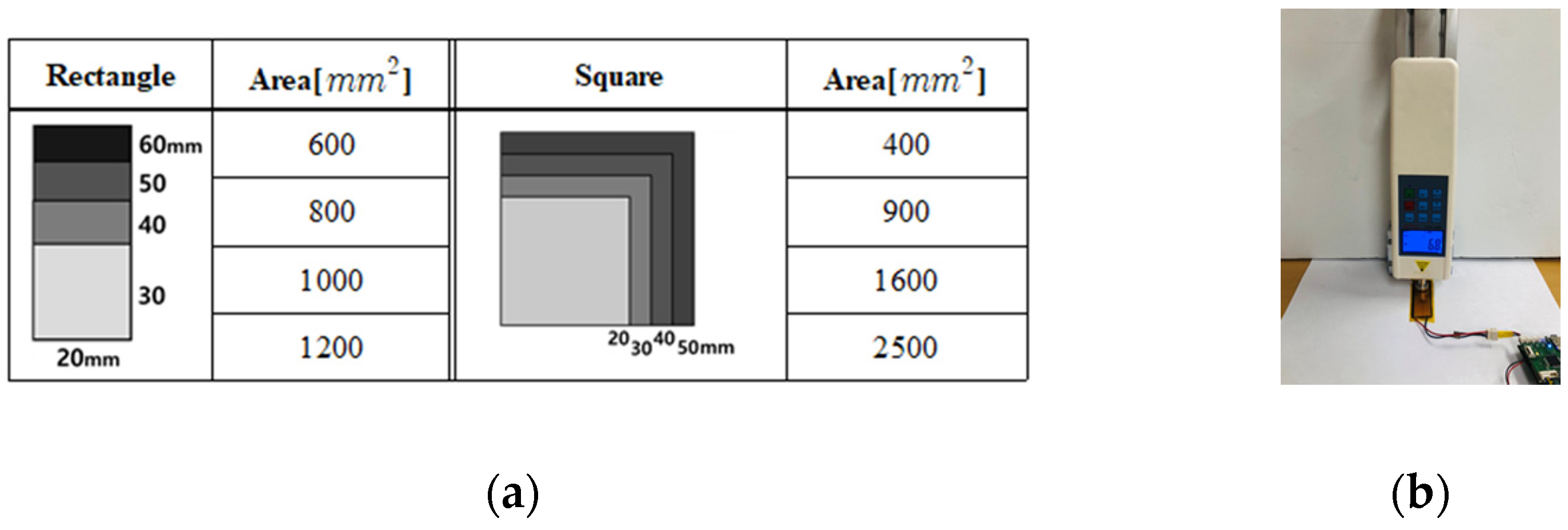
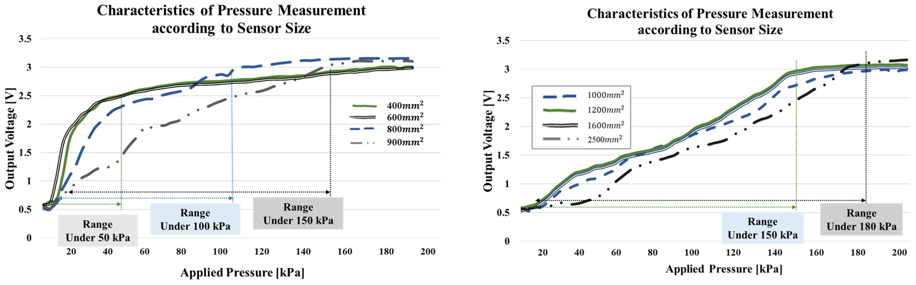
2.2.1. Check the Individual Pressure Range inside the Socket and Select the Fabrication Size of the Sensor
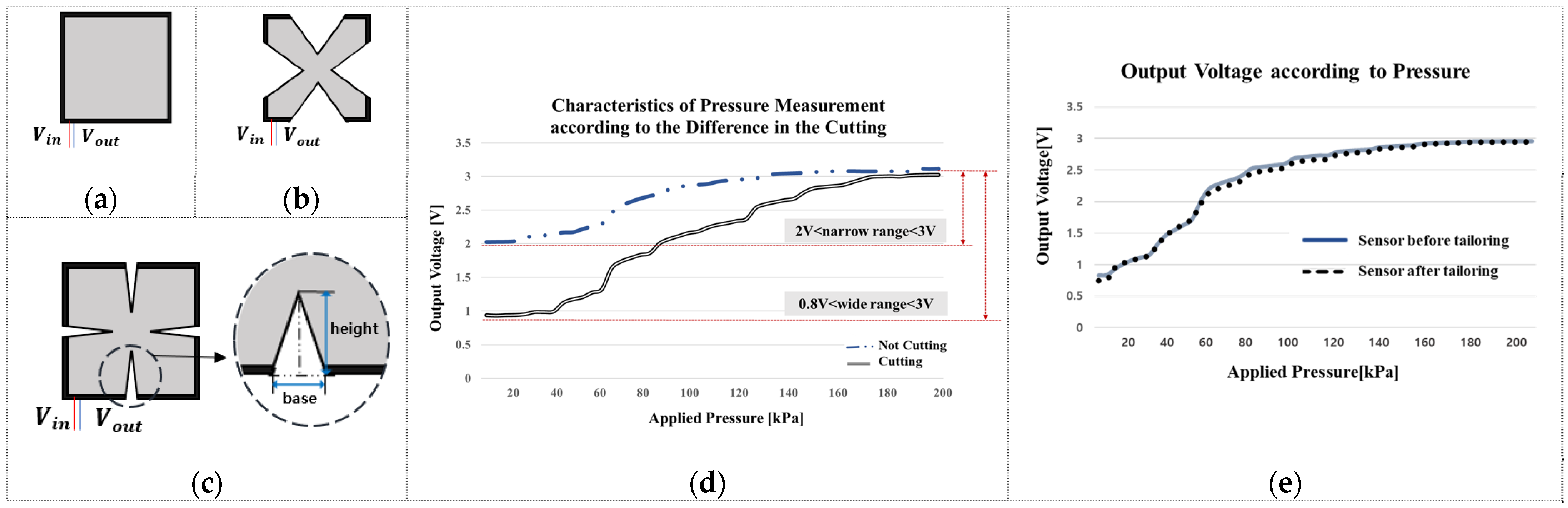
2.2.2. Cutting the Outer Part of the Sensor according to the Flexion of Attachment Areas
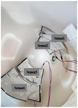
2.2.3. Attaching Sensors and Wearing the Prosthetic Leg
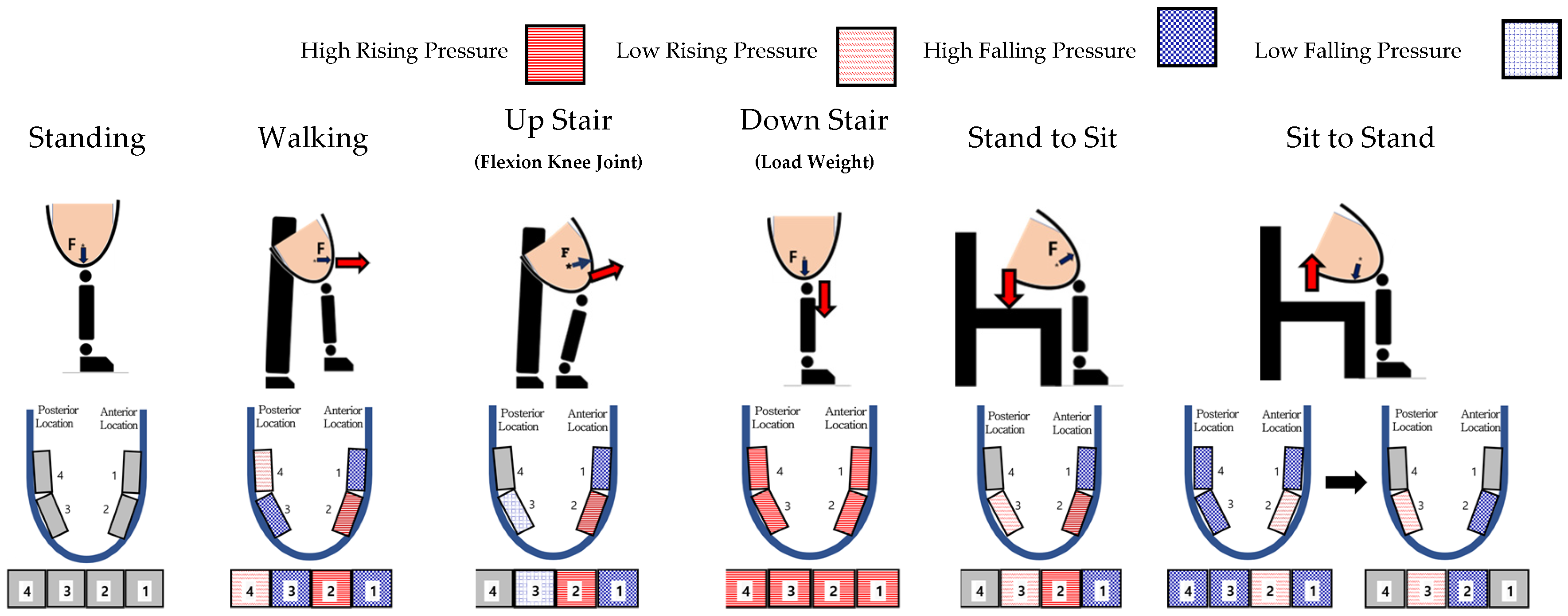
2.2.4. Detection of the User’s Intention according to Movements of the Lower Limb
3. Experiments and Results
3.1. Guideline for Fabricating Pressure Sensors for Individual Applications
3.2. Experiment and Performance Verification according to the Application Process of the Lower Limb Movement Intention Detection System
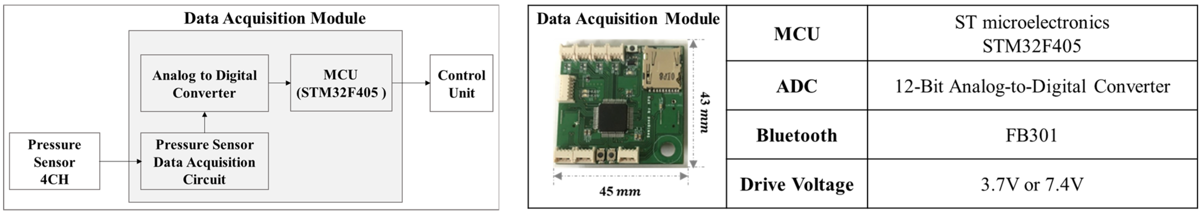
3.2.1. Configuration of the Velostat-Film-Based Pressure Sensor System
3.2.2. Experimental Participant Information
3.2.3. Experiments according to the Application Process of the Lower Limb Movement Intention Detection System: Initial Sensor Application Step
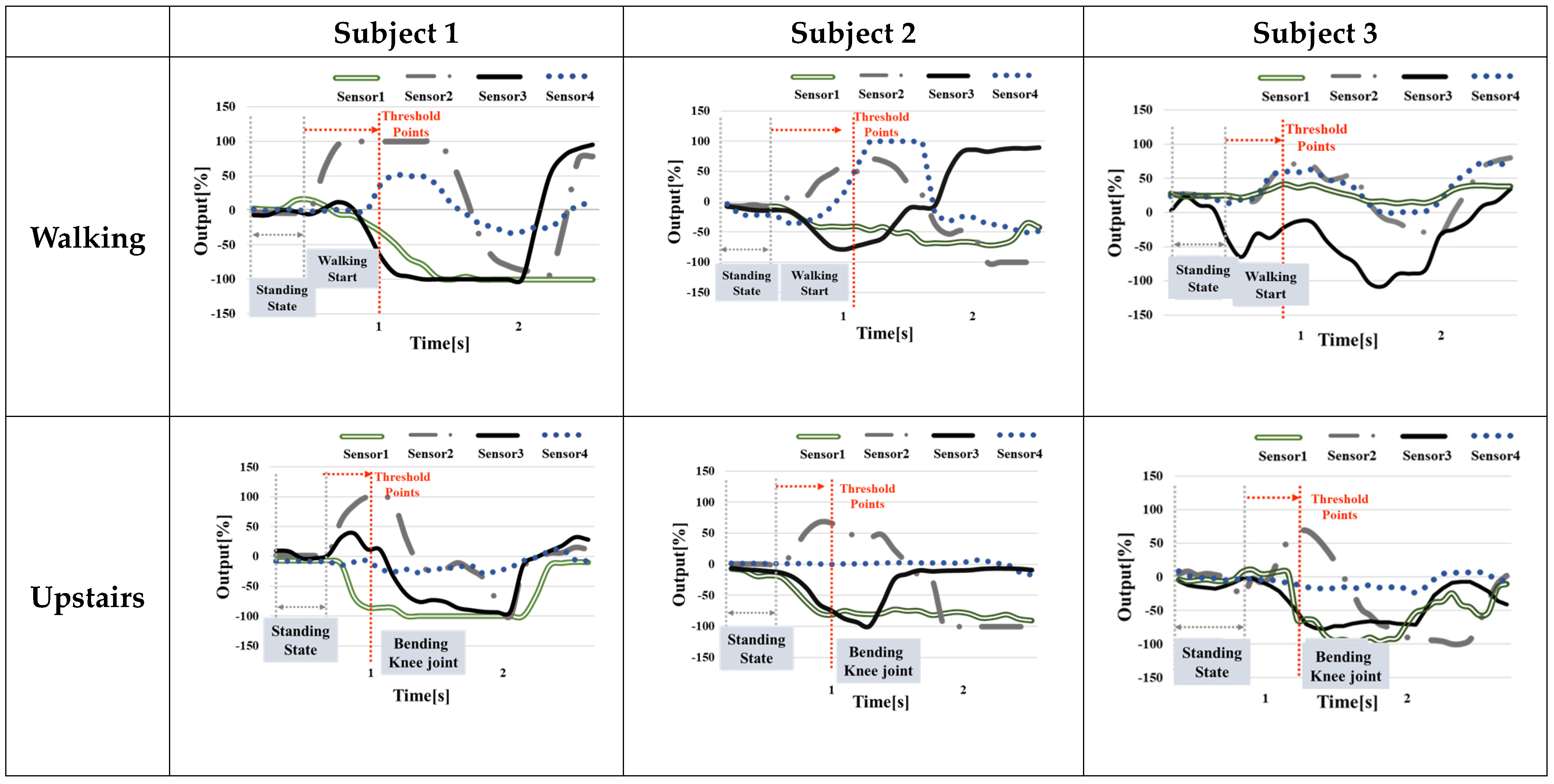
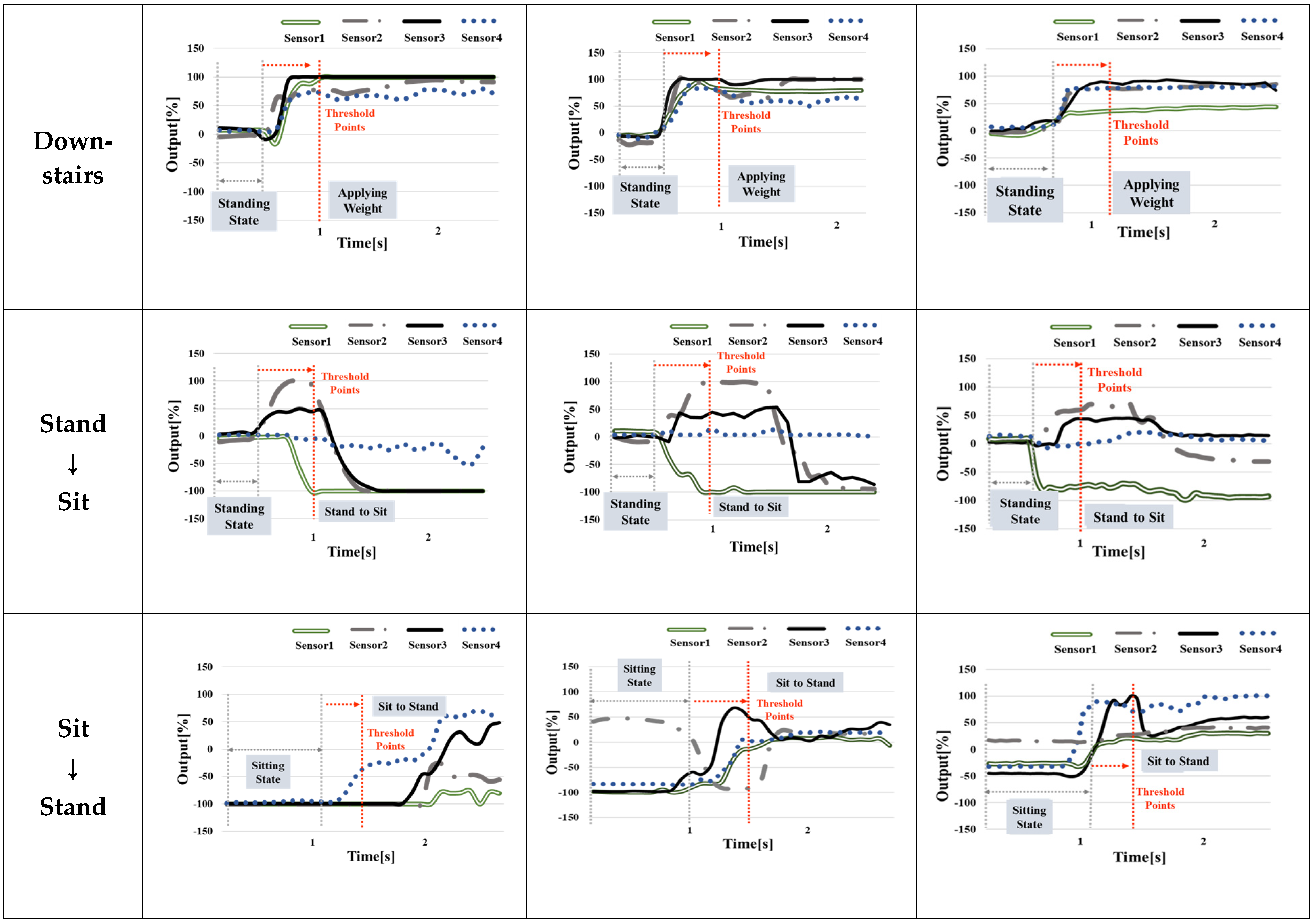
3.2.4. Experiments according to the Application Process of the Lower Limb Movement Intention Detection System: Performing Six Locomotion Movements
4. Discussion
5. Conclusions
Author Contributions
Funding
Institutional Review Board Statement
Informed Consent Statement
Data Availability Statement
Conflicts of Interest
References
- Paternò, L.; Ibrahimi, M.; Gruppioni, E.; Menciassi, A.; Ricotti, L. Sockets for Limb Prostheses: A Review of Existing Technologies and Open Challenges. IEEE Trans. Biomed. Eng. 2018, 65, 1996–2010. [Google Scholar] [CrossRef] [PubMed]
- Fluit, R.; Prinsen, E.C.; Wang, S.; Kooij, H. A Comparison of Control Strategies in Commercial and Research Knee Prostheses. IEEE Trans. Biomed. Eng. 2020, 67, 277–290. [Google Scholar] [CrossRef] [PubMed]
- Eom, S.H.; Na, S.J.; Lee, S.H.; Park, S.H.; Lee, E.H. A Preliminary Study of Ankle Variable Hybrid Above-knee Prostheses. In Proceedings of the 16th International Conference on Informatics in Control, Automation and Robotics, Prague, Czech Republic, 29–31 July 2019; Volume 1, pp. 789–794. [Google Scholar]
- Grimmer, M.; Seyfarth, A. Mimicking human-like leg function in prosthetic limbs. In Neuro-Robotics; Springer: Berlin/Heidelberg, Germany, 2014; pp. 105–155. [Google Scholar]
- Windrich, M.; Grimmer, M.; Christ, O.; Rinderknecht, S.; Beckerle, P. Active lower limb prosthetics: A systematic review of design issues and solutions. In Robotics: Science and Systems 2013; Springer: Berlin/Heidelberg, Germany, 2014. [Google Scholar]
- Quintero, D.; Villarreal, D.J.; Gregg, R.D. Preliminary experiments with a unified controller for a powered knee-ankle prosthetic leg across walking speeds. In Proceedings of the IEEE International Conference on Intelligent Robots and Systems, Daejeon, Republic of Korea, 9–14 October 2016; pp. 5427–5433. [Google Scholar]
- Lawson, B.E.; Varol, H.A.; Huff, A.; Erdemir, E.; Goldfarb, M. Control of stair ascent and descent with a powered transfemoral prosthesis. IEEE Trans. Neural Syst. Rehabil. Eng. 2013, 21, 466–473. [Google Scholar] [CrossRef] [PubMed]
- Johansson, J.L.; Sherrill, D.M.; Riley, P.O.; Bonato, P.; Herr, H. A Clinical Comparison of Variable-Damping and Mechanically Passive Prosthetic Knee Devices. Am. J. Phys. Med. Rehabil. 2005, 84, 563–575. [Google Scholar] [CrossRef] [PubMed]
- Ottobock Homepage (C-Leg 4). Available online: https://www.ottobock.com/ko-kr/product/3C88-3~23C98-3 (accessed on 9 January 2024).
- Ottobock Homepage (Genium). Available online: https://www.ottobock.com/en-gb/product/3B1-3 (accessed on 9 January 2024).
- Ossur Homepage (Rheo Knee). Available online: www.ossur.com/en-us/prosthetics/knees/rheo-knee (accessed on 9 January 2024).
- Zhang, F.; Liu, M.; Huang, H. Effects of Locomotion Mode Recognition Errors on Volitional Control of Powered Above-Knee Prostheses. IEEE Trans. Neural Syst. Rehabil. Eng. 2015, 23, 64–72. [Google Scholar] [CrossRef]
- Simon, A.M.; Ingraham, K.A.; Spanias, J.; Young, A.J.; Finucane, S.B.; Halsne, E.G.; Hargrove, L.J. Delaying ambulation mode transition decisions improves accuracy of a flexible control system for powered knee-ankle prosthesis. IEEE Trans. Neural Syst. Rehabil. Eng. 2016, 25, 1164–1171. [Google Scholar] [CrossRef] [PubMed]
- Young, A.J.; Simon, A.M.; Hargrove, L.J. A Training Method for Locomotion Mode Prediction Using Powered Lower Limb Prostheses. IEEE Trans. Neural Syst. Rehabil. Eng. 2014, 22, 671–677. [Google Scholar] [CrossRef]
- Hu, B.; Simon, A.M.; Hagrove, L. Deep Generative Models with Data Augmentation to Learn Robust Representations of Movement Intention for Powered Leg Prostheses. IEEE Trans. Med Robot. Bionics 2019, 1, 267–278. [Google Scholar] [CrossRef]
- Liu, Z.; Lin, W.; Geng, Y.; Yang, P. Intent Pattern Recognition of Lower-limb Motion Based on Mechanical Sensors. IEEE/CAA J. Autom. Sin. 2017, 4, 651–660. [Google Scholar] [CrossRef]
- Hunt, G.R.; Hood, S.; Lenzi, T. Stand-Up, Squat, Lunge, and Walk with a Robotic Knee and Ankle Prosthesis under Shared Neural Control. IEEE Open J. Eng. Med. Biol. 2021, 2, 267–277. [Google Scholar] [CrossRef]
- Zhao, H.; Reher, J.; Horn, J.; Paredes, V. Realization of Stair Ascent and Motion Transitions on Prostheses utilizing Optimization-Based Control and Intent Recognition. In Proceedings of the IEEE International Conference on Rehabilitation Robotics, Singapore, 11–14 August 2015; pp. 265–270. [Google Scholar]
- Woodward, R.B.; Simon, A.M.; Seyforth, E.A.; Hargrove, L.J. Real-Time Adaptation of an Artificial Neural Network for Transfemoral Amputees Using a Powered Prosthesis. IEEE Trans. Biomed. Eng. 2022, 69, 1202–1211. [Google Scholar] [CrossRef] [PubMed]
- Jasni, F.; Hamzaid, N.A.; Muthalif, A.G.A.; Zakaria, Z.; Shasmin, H.N.; Ng, S.C. In-Socket Sensory System for Transfemoral Amputees Using Piezoelectric Sensors: An Efficacy Study. IEEE/ASME Trans. Mechatron. 2016, 21, 2466–2476. [Google Scholar] [CrossRef]
- Zheng, E.; Wang, L.; Wei, K.; Wang, Q. A Noncontact Capacitive Sensing System for Recognizing Locomotion Modes of Transtibial Amputees. IEEE Trans. Biomed. Eng. 2014, 61, 2911–2920. [Google Scholar] [CrossRef]
- Noll, V.; Weber, P.; Scortecci, S.; Beckerle, P.; Rinderknecht, S. A Sensor to Acquire the Relative Movement between Residual Limb and Prosthetic Socke. In Proceedings of the IEEE International Conference on Systems, Man, and Cybernetics, Budapest, Hungary, 9–12 October 2016. [Google Scholar]
- Lara-Barrios, C.M.; Blanco, A.; Guzman, C.H.; Bustamante Valles, K.D. Literature review and current trends on transfemoral powered prosthetics. J. Saf. Res. 2017, 63, 29–41. [Google Scholar] [CrossRef]
- Tabor, J.; Agcayazi, T.; Fleming, A.; Thompson, B.; Kapoor, A.; Bozkurt, A.; Ghosh, T.K. Textile-Based Pressure Sensors for Monitoring Prosthetic-Socket Interfaces. IEEE Sens. J. 2021, 21, 9413–9422. [Google Scholar] [CrossRef]
- Shin, J.W.; Eom, S.H.; Lee, C.U.; Lee, E.H. Techniques for Improving the Reliability of Prosthesis Wearer Muscle Signals Using Pressure and EMG Sensors. In Proceedings of the International Conference of the IEEE Engineering in Medicine and Biology Society, Berlin, Germany, 23–27 July 2019. [Google Scholar]
- Na, S.J.; Shin, J.W.; Eom, S.H.; Lee, E.H. A Study on the Activation of Transfemoral Prostheses Focused on the Development of a Decision Tree based Gait Phase Identification Algorithm. In Proceedings of the International Conference on Informatics in Control, Prague, Czech Republic, 29–31 July 2019. [Google Scholar]
- Mahmud, S.; Khandakar, A.; Chowdhury, M.E.H.; Reaz, M.B.I.; Kiranyaz, S.; Mahbub, J.B.; Ali, S.H.M.; Bakar, A.A.; Alhatou, M.; Moniem, M.A. Design and Implementation of a Complete Wearable Smart Insole Solution to Measure Plantar Pressure and Temperature. arXiv 2022, arXiv:2206.07779. [Google Scholar]
- El-Sayed, A.M.; Hamzaid, N.A.; Tan, K.Y.S.; Osman, N.A.A. Detection of Prosthetic Knee Movement Phases via In-Socket Sensors: A Feasibility Study. Sci. World J. 2015, 2015, 923286. [Google Scholar] [CrossRef]
- Yoo, S.B.; Lim, Y.K.; Eom, S.H.; Lee, E.H. Method of Walking Surface Identification Technique for Automatic Change of Walking Mode of Intelligent Bionic Leg. J. Rehabil. Welf. Eng. Assist. Technol. 2017, 11, 81–89. [Google Scholar]
- Fatema, A.; Poondla, S.; Mishra, R.B.; Hussain, A.M. A Low-Cost Pressure Sensor Matrix for Activity Monitoring in Stroke Patients Using Artificial Intelligence. IEEE Sensors J. 2021, 21, 9546–9552. [Google Scholar] [CrossRef]
- Yuan, L.; Qu, H.; Li, J. Velostat Sensor Array for Object Recognition. IEEE Sensors J. 2022, 22, 1692–1704. [Google Scholar] [CrossRef]
- Dzedzickis, A.; Sutinys, E.; Bucinskas, V.; Samukaite-Bubniene, U.; Jakstys, B.; Ramanavicius, A.; Morkvenaite-Vilkonciene, I. Polyethylene-Carbon Composite (Velostat®) Based Tactile Sensor. Polymers 2020, 12, 2905. [Google Scholar] [CrossRef] [PubMed]
- Park, N.Y.; Eom, S.H.; Lee, E.H. A Study on the Development of In-Socket Pressure Change Measurement Sensor for Estimation Locomotion Intention of Intelligent Prosthetic leg User. J. IKEEE 2022, 26, 249–256. [Google Scholar]
- Ferreira, A.; Lanceros-Mendez, S. Piezoresistive Polymer-Based Materials for Real-Time Assessment of the Stump/Socket Interface Pressure in Lower Limb Amputees. IEEE Sens. J. 2017, 17, 2182–2190. [Google Scholar] [CrossRef]
- Herr, H.; Wilkenfeld, A. User-adaptive control of a magnetorheological prosthetic knee. Ind. Robot. Int. J. Robot. Res. Appl. 2003, 30, 42–55. [Google Scholar] [CrossRef]
- Dumbleton, T.; Buis, A.W.P.; McFadyen, A.; McHugh, B.F.; McKay, G.; Murray, K.D.; Sexton, S. Dynamic interface pressure distributions of two transtibial prosthetic socket concepts. J. Rehabil. Res. Dev. 2009, 46, 405–415. [Google Scholar] [CrossRef]
- Dou, P.; Jia, X.; Suo, S.; Wang, R.; Zhang, M. Pressure distribution at the stump/socket interface in transtibial amputees during walking on stairs, slope and non-flat road. Clin. Biomech. 2006, 21, 1067–1073. [Google Scholar] [CrossRef]
- Beil, T.L.; Street, G.M.; Covey, S.J. Interface pressures during ambulation using suction and vacuum assisted prosthetic sockets. J. Rehabil. Res. Dev. 2007, 39, 693–700. [Google Scholar]


| 1. Check the individual pressure range inside the socket and select the fabrication size of the sensor |
| 2. Cut the outer part of the sensor in accordance with the flexion of the attachment area |
| 3. Attach the sensor and wear the prosthetic leg |
| 4. Detect the user intention according to the movement of the lower limb |
| Range [kPa] | Sensor Size [mm2] | Considerations for Application |
|---|---|---|
| Under 50 | 400, 600 | Narrow area and pressure range allow for large changes in small pressure. Suitable for use in areas with small muscle mass or for children and low-weight users. |
| Under 100 | 800 | Suitable for applications to areas with pressure generation of 100 kPa or less to users. |
| Under 150 | 900, 1000, 1200, 1600 | Suitable for applications to areas with pressure generation of 150 kPa or less to users. |
| Under 180 | 2500 | Large area and pressure range: Suitable for use in areas that require a detailed check of muscle movement or in users with high weight and high activity. |
| R0 | R60 | R80 | R100 | R120 | |
|---|---|---|---|---|---|
| Pictures |  |  |  |  |  |
| Image |  | 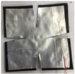 | 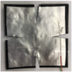 | 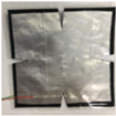 | 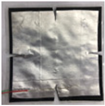 |
| Cutting amount [mm] | Base 0 (0%) Height 0 (0%) | Base 7 (14%) Height 14 (28%) | Base 6 (12%) Height 12 (24%) | Base 5 (10%) Height 10 (20%) | Base 4 (8%) Height 8 (16%) |
| Cutting rate [%] (Loss Rate) | 0 | 7.84 | 5.76 | 4 | 2.56 |
| Subject 1 | Subject 2 | Subject 3 | |
|---|---|---|---|
| Physical Conditions | Height 171 cm, Weight 82 kg, Male Rectus Amputee | Height 155 cm, Weight 50 kg, Female Non-Amputated | Height 174 cm, Weight 75 kg, Male Non-Amputated |
| Selected Sensor [mm2] | Sensor 1 1600 (about 150 kPa) | Sensor 1 800 (about 100 kPa) | Sensor 1 1600 (about 150 kPa) |
| Sensor 2 1600 (about 150 kPa) | Sensor 2 800 (about 100 kPa) | Sensor 2 800 (about 100 kPa) | |
| Sensor 3 2400 (over 180 kPa) | Sensor 3 2500 (over 180 kPa) | Sensor 3 2500 (over 180 kPa) | |
| Sensor 4 2400 (over 180 kPa) | Sensor 4 2500 (over 180 kPa) | Sensor 4 2500 (over 180 kPa) | |
| Cutting | Sensor 1 Base 8%, Height 16% | Sensor 1 Base 8%, Height 16% | |
| (flexion radius about 120) | (flexion radius about 120) | ||
| Sensor 2 Base 10%, Height 20% | Sensor 2 Base 10%, Height 20% | ||
| (flexion radius about 100) | (flexion radius about 100) | ||
| Sensor 3 Base 10%, Height 20% | Sensor 3 Base 14%, Height 28% | ||
| (flexion radius under 60) | (flexion radius under 60) | ||
| Sensor 4 Base 8%, Height 16% | Sensor 4 Base 8%, Height 16% | ||
| (flexion radius about 120) | (flexion radius about 120) | ||
| Image |  |  | 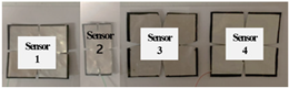 |
 |  |  | |
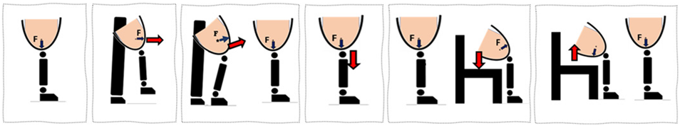 |
| (1) Standing |
| (2) Level locomotion in a standing posture |
| (3) Performing knee joint flexion in a standing posture (predefined posture for moving upstairs) |
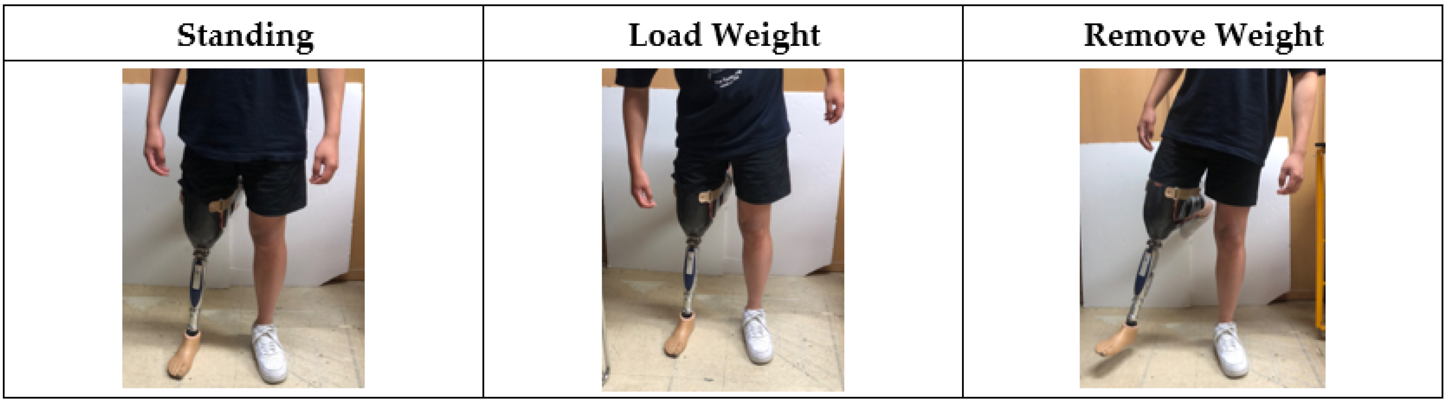
| (4) Load application in a standing posture (predefined posture for moving downstairs) |
| (5) Sitting in a standing posture |
| (6) Standing in a sitting posture |
| Pressure Change of Sensor 4 [%] (Upper of Biceps Femoris) | Pressure Change of Sensor 3 [%] (Lower of Biceps Femoris) | Pressure Change of Sensor 2 [%] (Lower of Rectus Femoris) | Pressure Change of Sensor 1 [%] (Upper of Rectus Femoris) | ||
|---|---|---|---|---|---|
| Standing | 0 | 0 | 0 | 0 |  |
| Walking | Rising 0→50 | - | Rising 0→50 | Decreasing 0→50 |  |
| Up Stair | 0 | - | Rising 0→50 | Decreasing 0→0 |  |
| Down Stair | Rising 0→100 | Rising 0→100 | Rising 0→100 | Rising 0→50 |  |
| Stand to Sit | 0 | Rising 0→50 | Rising 0→50 | Decreasing 0→0 |  |
| Sit to Stand | Rising 0 or less→0 | Rising 0 or less→0 | - | Rising 0 or less→0 | 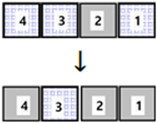 |
Disclaimer/Publisher’s Note: The statements, opinions and data contained in all publications are solely those of the individual author(s) and contributor(s) and not of MDPI and/or the editor(s). MDPI and/or the editor(s) disclaim responsibility for any injury to people or property resulting from any ideas, methods, instructions or products referred to in the content. |
© 2024 by the authors. Licensee MDPI, Basel, Switzerland. This article is an open access article distributed under the terms and conditions of the Creative Commons Attribution (CC BY) license (https://creativecommons.org/licenses/by/4.0/).
Share and Cite
Park, N.-Y.; Eom, S.-H.; Lee, E.-H. A Study on the Fabrication of Pressure Measurement Sensors and Intention Verification in a Personalized Socket of Intelligent Above-Knee Prostheses: A Guideline for Fabricating Flexible Sensors Using Velostat Film. Appl. Sci. 2024, 14, 734. https://doi.org/10.3390/app14020734
Park N-Y, Eom S-H, Lee E-H. A Study on the Fabrication of Pressure Measurement Sensors and Intention Verification in a Personalized Socket of Intelligent Above-Knee Prostheses: A Guideline for Fabricating Flexible Sensors Using Velostat Film. Applied Sciences. 2024; 14(2):734. https://doi.org/10.3390/app14020734
Chicago/Turabian StylePark, Na-Yeon, Su-Hong Eom, and Eung-Hyuk Lee. 2024. "A Study on the Fabrication of Pressure Measurement Sensors and Intention Verification in a Personalized Socket of Intelligent Above-Knee Prostheses: A Guideline for Fabricating Flexible Sensors Using Velostat Film" Applied Sciences 14, no. 2: 734. https://doi.org/10.3390/app14020734
APA StylePark, N.-Y., Eom, S.-H., & Lee, E.-H. (2024). A Study on the Fabrication of Pressure Measurement Sensors and Intention Verification in a Personalized Socket of Intelligent Above-Knee Prostheses: A Guideline for Fabricating Flexible Sensors Using Velostat Film. Applied Sciences, 14(2), 734. https://doi.org/10.3390/app14020734