Abstract
Off-shore wind power plants can be connected to the on-shore grid using diode rectifier HVdc links. As diode rectifiers are passive converters, off-shore WPPs require grid-forming capability. This paper shows how to improve the WTG dynamic response and the voltage and current harmonic rejection by using -based controllers. The paper explains how to synthesise three different voltage controllers: the first is a single-loop controller, the second is a cascaded controller and the third is a proportional–resonant controller that is optimised using synthesis. The three -based controllers improve the performance and the robustness obtained with a benchmark case PR controller tuned using the root locus technique. All the controllers are designed in continuous time and implemented in discrete time, applying bilinear discretisation with a sampling rate of 0.25 ms. Detailed PSCAD simulations validate the improvement of the performance and robustness, as well as an improvement in the harmonic rejection. The single controller shows the best combined characteristics of all tried controllers, at the expense of losing the separation between voltage and current control loops.
1. Introduction
Advanced control design and accurate modelling and simulation of wind power plants (WPP) are key to increasing the efficiency and robustness of this class of systems. Controllers based on synthesis have been used in Voltage Source Converter (VSC) control [,]. Nevertheless, earlier studies overlooked the use of controllers for grid-forming converters. Therefore, they did not consider the voltage control design nor the cascaded voltage and current control design.
The use of HVdc diode rectifier (DR) stations reduces the investment cost of the off-shore WPP and increases the systems’ resilience and efficiency []. Siemens asserts that using HVdc DR stations can potentially decrease the connection cost of WPP by as much as 30% [,].
Grid-forming capability is a requirement for DR-based HVdc links. Several control alternatives have been proposed for this purpose []. The authors in [] proposed a cascade control loop using synthesis for a micro-source inverter, but just considered uncertainty in the PWM LC filter parameters. In [], the authors considered a sliding-mode control for the current loop, while the voltage outer loop controller was based on mixed . Still, the controller was not designed considering the operating modes with which the WTG was going to operate. In [], the authors proposed a grid-forming controller that can synchronise with the ac grid for DR-based off-shore WPPs, but the operating modes of the WTGs were not considered during the controller design procedure. In [], an -based grid-forming controller was proposed but for grid-following converters. In [], the authors used passivity theory to design a grid-forming controller, but it was not considered for DR-based WPPs nor did they consider the operating modes of the converter. The authors in [] proposed validating grid-forming converters using a co-simulation approach between the mosaic framework and a power system. In [], the authors used -synthesis with the purpose of optimising a grid-forming controller by considering the operating modes of the WPP, but just a single-loop voltage control was considered. In [], the influence in the stability of the parameters of the voltage control for a grid-forming WTG was analysed, but just for one of the operating modes of the grid-forming converter. The authors in [] implemented the typical P/ Q/V droops in the WTGs, proposing a transmission active power control for the off-shore WPP, where the on-shore MMC modifies the HVdc voltage to maintain the off-shore ac grid frequency. The problem is that the power transmission requires fast communication for its operation. In [], the authors proposed a grid-following control for the WTGs of a DR-based WPP. The main problems were the islanded operation and the black-start operation of the WPP.
Such grid-forming wind turbine converters need to show adequate performance during islanding operation at no-load (ISL no-load), during power transmission through the DR–HVdc link (DR-connected) and also during islanding operation at rated-load if the WPP is used for black-start or to supply local loads (ISL rated-load). Any control strategy for such grid-forming converters should consider these three different modes of operation.
This paper evaluates current control alternatives that use -based design [,] to improve the grid-forming WTG dynamic performance. Three designs based on synthesis are calculated. The first consists of a cascaded control based on . Therefore, two controllers are calculated (voltage controller as outer loop and current controller as inner loop). The second design uses the cascaded control based on proportional–resonant regulators, with the controller parameters tuned using synthesis for fixed-structure controllers. The last controller calculates a voltage control based on synthesis that uses the same information as the other controllers. Each controller’s robustness is tested with the WTGs working in different scenarios (islanded no-load, islanded rated-load and DR-connected). A harmonic distortion analysis is carried out to validate the improvement of harmonic rejection and stability margins achieved using -based grid-forming controllers.
This paper’s main contribution is a methodology to design three different controllers, applying the technique for the WTG control of DR-based WPPs. The controller design mainly aims to operate the WTGs in different grid structures. This means that the system impedance changes due to the number of connected cables, WTGs or the DR.
The structure of this paper includes the following sections. The system description used to validate the controllers is described in the second section, while the third section includes the controllers’ design procedure. The fourth section shows an analysis of the designed controllers regarding performance, robustness and harmonic rejection. The conclusions are included in the last section.
2. System Description and Problem Statement
This section includes the off-shore WPP under study in this paper to analyse and design grid-forming controllers.
Figure 1 illustrates the comprehensive system diagram, featuring a 1.2 GW off-shore WPP distributed across three clusters, each with a 400 MW capacity. The WPP establishes a connection to an on-shore Modular Multi-level Converter (MMC) through a DR–HVdc link. Each WPP cluster consists of 50 8 MW type-4 WTGs, connected to a 66 kV collector. The use of aggregated WTGs allows WPP complexity reduction. For that, an aggregated WTG models each string of WTG, as shown in Figure 1. The used WTG aggregation technique is proposed in []. Aggregating each string allows a reasonable computational cost reduction in simulations while keeping the complete dynamics of the DR–HVdc stages. The realistic model considers saturation for all transformer models (WTG and DR).
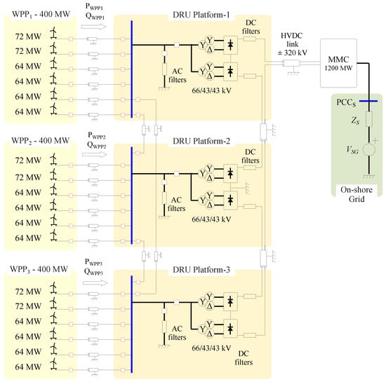
Figure 1.
DR-based off-shore WPP [].
The DR–HVdc system is composed of three DR platforms []. Each platform includes two 12-pulse DR of 200 MW, with a parallel connection on the ac side and a series connection on the dc side.
As Figure 1 shows, the clusters WPP-i () are connected to the DR platforms using the off-shore ac collector grid. Each DR platform includes ac and dc filters. Lumped pi-parameter cable models are used for the off-shore array cable.
DR stations are connected to the on-shore MMC converter using an export HVdc cable, modelled using a distributed frequency-dependent parameters model. The on-shore MMC operates by controlling the HVdc grid voltage and giving support with reactive power to a high-SCR on-shore grid. The electrical system parameters are listed in Table A1.
2.1. Wind Turbine Model
Figure 2 shows the WTG grid-side converter model and its control strategy. WTG’s grid-side converter consists of a three-phase h-bridge converter, an LC filter and a transformer.
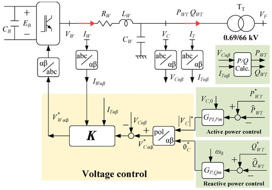
Figure 2.
Control strategies for the grid-side converter of each grid-forming WTG [].
The LC filter and the WTG transformer dynamics of the WTG in Figure 2 are described in Equations (1) and (2):
where and are the resistance and the inductance values of the inductor LC filter, is the Capacitor LC filter and and are the resistance and the inductance value of the WTG transformer. and are the h-bridge converter output voltage and current, is the capacitor voltage and and are the high-side transformer voltage and the low-side transformer current.
Note that the current output should be multiplied by to obtain the high-voltage-side transformer current. The machine-side converter of each WTG is modelled as a DC voltage source for simplification.
The grid-forming converter control loop should perform adequately in islanded operation (no-load and rated-load) and deliver full power to the DR–HVdc station. These three operational modes can be considered by changing and values:
- Islanded no-load: This mode considers a WTG before connecting to the off-shore AC grid. The WTG operates in an open circuit, and the resistance transformer value can be considered . The inductance transformer value remains the same;
- Islanded rated-load: This mode considers a WTG before connecting to the off-shore AC grid with an equivalent resistive load equal to the rated capacity. In this mode, the equivalent value of the resistance transformer in pu is . The inductance transformer value remains the same;
- DR-connected: This mode considers the WTG, while the power transmission is via the DR–HVdc link. In this mode, the equivalent values of the resistance and inductance transformer in pu are , .
Figure 3 shows the frequency response of each considered operating mode. As Figure 3 shows, both the resonant peak amplitude and frequency depend on the case being considered. Moreover, an anti-resonant peak (at 640 Hz) in the current’s amplitude diagram appears when the system is DR-connected. On the other hand, both resonant and anti-resonant peaks are much smaller when considering islanded operation at rated-load, as the considered resistive load would introduce additional damping.
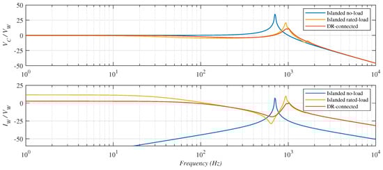
Figure 3.
Frequency response of each operating mode seen from a WTG.
2.2. Active and Reactive Power Control
As described in Figure 2, the voltage control system whose design is the goal of this work is a “slave”, one in a hierarchical scheme, where voltage references come from active and reactive power control blocks, based on P/V Q/ droops (DR-based WPP requires P/V Q/ droop instead of P/ Q/V droop to avoid a centralised control to change the off-shore ac voltage for power transmission by the DR []). The active power transmission depends on the DR voltage, which can be calculated as follows:
where , B is the rectifier bridges number, N and are the DR transformer ratio and leakage reactance and is the off-shore ac voltage in dq frame.
The power control design is proposed in []. The power controllers are the following:
The power control tuning does not consider the inner voltage control loop. Nevertheless, as examples later show, there are interactions because time constants are similar in some cases; we would recommend checking possible design alternatives, using a combined voltage/power multivariable control that, however, is intentionally out of the scope of this contribution.
2.3. Voltage Control Tuning
The grid-side converter control shown in Figure 2 is
where the notation indicates that it will be implemented in discrete time, with a sampling period of s.
This paper has included a standard control procedure as a benchmark for the proposed controllers. Figure 4 shows the considered control scheme. Incorporating a cascaded control structure with voltage and current control in the outer and inner loops; the design of both controllers aligns with the principles outlined in []. The voltage and current controllers are designed as PI controllers within a rotating frame of reference, accounting for specified settling time and overshoot criteria. Subsequently, a frequency shift to a PR structure is applied using (7), as detailed in [,]:
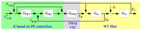
Figure 4.
Benchmarck PR-based voltage control of the grid-side converter.
Figure 4 shows the PR control structure with the considered plant. The effects of the PWM and the measurement delay are considered in . and models the inductor and capacitor filter dynamics. , and are
The tuning of the inner current controller is performed to attain a settling time of 7.5 ms and ensure an overshoot below 10%, considering PWM converter delays ( used as discretisation artifact []).
The outer voltage controller’s design considers the current loop’s closed-loop transfer function, targeting a settling time lower than 25 ms and an overshoot lower than 10%.
The equivalent PR controller is obtained by applying a frequency shift to the voltage and current controllers (7). The current and voltage PR controller parameters are listed below.
Therefore, the PR based voltage controller is, in transfer matrix form,
where and are
A discretisation of the obtained controller is carried out using the bilinear approximation with a sample time of 0.25 ms and prewarping at 50 Hz.
The controller parameters are shown in Table 1.

Table 1.
Proportional–resonant control parameters of the PR benchmark controller.
2.4. Problem Statement
The main objective of this paper is to propose a methodology to design -based controllers for grid-forming WTGs. The paper shows the design of three controllers that consider the modes of operation of a DR-based WPP. The design includes defining the weights to consider unstructured uncertainty and the desired performance. The paper shows the results that can be obtained using the same number of sensors and how the performance is improved compared to a benchmark controller based on a cascade PR control.
Moreover, the paper includes an analysis of the robustness achieved with all the controllers and the harmonic rejection that can be achieved by each controller on the grid system.
3. -Based Control Strategies
The main objective of this paper is to define a procedure for the synthesis of the controller in (6) that improves the robustness of the system. Four controller designs are considered:
- Proportional–Resonant Voltage Control tuned using Root Locus: This standard control procedure has been included as a benchmark for the other techniques (this design is included above as the benchmark controller);
- Cascaded Voltage and Current Control based on synthesis: The outer voltage loop and the inner current loop are individual controllers based on synthesis;
- Proportional–Resonant Voltage Control tuned using synthesis: The parameters of the regulators have been tuned using synthesis;
- Voltage Control based on synthesis: A single voltage controller, i.e., without internal current loop.
The design alternatives 1 and 2 follow a cascade control structure as the benchmark controller. One uses synthesis for the PR-based control parameter tuning, while the third calculates state-space voltage and current controllers based on synthesis. The last design alternative calculates a single-loop voltage controller based on synthesis.
3.1. Design Alternative 1: Cascaded Voltage and Current Control Based on Synthesis
To improve the robustness of the controller with a cascaded structure, a voltage control and a current control have been obtained using synthesis to replace each of the two root-locus PR controllers designed above. Considering the plants described in (9) and (10), the first step is the zero-order hold (ZOH) discretisation of both plants, using a sampling rate of ms. Additionally, the PWM delay is considered by adding a sample-time delay (i.e., ). Then, the generalised plant shown in Figure 5 is obtained.
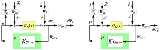
Figure 5.
Generalised plant for voltage and current control based on synthesis: Current (left); Voltage (right).
Be aware that optimal design does not explicitly include uncertainty. Instead, this uncertainty needs to be introduced through the assignment of weights. For example, a widely acknowledged practice involves assigning weight to the output of the generalised plant associated with control action, thereby ensuring robustness against unstructured additive uncertainty. However, the favourable computational aspects of synthesis (convex optimisation) compared to the non-convex iterative procedures for structured uncertainty in, say, -synthesis [,] made the choice in this work.
3.1.1. Design of Current Control Loop
The generalised current plant (Figure 5, left) has and as input weights, and and as outputs weights. The generalised weighted current plant can be expressed as
Each weight is designed with the following considerations:
- is the reference weight and includes the added uncertainty to the inductor filter and , considering the system in per-unit values. It is fixed to 1 for the output weights to be interpreted in standard position/tracking errors at given frequencies, as customary in the widely used mixed-sensitivity design [];
- is an input weight at the control action (i.e., at the input of ). Additionally, the robust control methodologies can reduce the steady-state error at the synchronous frequency, placing poles close to the imaginary axis (theory forbids unobservable output weights in the imaginary axis). Additionally, input disturbances at the control action are included to avoid the cancellation issues produced by the cancellation of complex poles close to the imaginary axis. This weight is also constant and is fixed to 0.1;
- is the control action weight. This weight is constant and fixed to 0.5 to allow the controller to apply two voltage units per each required ampere to fulfil transient saturation constraints. Also, it has an interpretation of robustness to additive uncertainty: limiting the high-frequency gain to 2 tolerates 0.5 units of plant uncertainty;
- is the current error weight. Three considerations have been taken into account. It is desired to obtain a controller with a resonant behaviour to achieve a small error at frequencies lower than 50 Hz and to reduce the controller’s effort at frequencies higher than 50 Hz. With these considerations, a weight in the form (15) has been tuned to achieve a closed-loop norm less than 1:where the variables are as follows:
- –
- in (15) is a constant value that represents the desired weight gain at low frequencies, which, given that the reference weight is unity, can be interpreted as the low-frequency (DC) position error in conventional control;
- –
- is a weight in the form (16)that has been tuned to accept errors lower than 0.02, setting a low-frequency gain inversely proportional to the accepted error. The gain at high frequencies is adjusted to be 200 times lower. The bandwidth of is selected so the H inf design shows a comparable settling time to the root locus PR design (7.5 ms). Therefore, the gain K in (16) is fixed to obtain a gain of 0 dB at 133.3 Hz (1/7.5 ms). Finally, a transformation to a resonant form at 50 Hz is applied to the weight using (7);
- –
- has the same structure as Equation (16), with a gain of 1 at low frequencies, a gain of 1/3 at high frequencies, and a bandwidth of 20 Hz;
- –
- is a gain tuned in order to achieve a norm less than 1.
Table 2.
Weight parameters for the current control.
Using the previously described weighting filters, a current control has been obtained by applying Matlab’s R2022b hinfsyn function.
3.1.2. Design of Outer Voltage Control Loop
Regarding voltage control, the generalised voltage plant (Figure 5, right) has and as input weights and and as outputs weights. The generalised weighted voltage plant in the discrete-time domain is
Each weight is designed according to the following criteria:
- is the reference weight, considering that the system is scaled to pu. The weight is a constant, fixed to 1 to ensure reference to output error sensitivity shaping, as in the current loop and standard mixed-sensitivity designs;
- is the weight of a perturbation at the control action, which, in this cascade structure, is the current command, assumed to be reasonably followed by the inner current loop previously designed. Considering that there is an inner current control loop that is not modelled in this design, this weight is fixed to 0.9;
- is the control action weight. This weight is fixed to 0.4 to allow the controller to apply 2.5 amperes per each required voltage unit;
Table 3.
Weight parameters for the Voltage Control.
The cascaded controller is
where and have been obtained independently by means of optimisation, with the weighting functions described previously (see Figure 6).
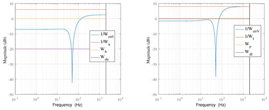
Figure 6.
Weights for cascaded design: Current (left); Voltage (right).
3.2. Design Alternative 2: Proportional–Resonant Voltage Control Tuned Using Synthesis
To obtain a more robust PR controller, the parameters of the cascaded PR controller have been tuned using synthesis for fixed-structure controllers. Note that the fixed-structure synthesis is a non-convex optimisation problem, which may become trapped at spurious local minima solutions in a generic case; nevertheless, it has been pursued here for the sake of comparison with the other alternatives.
Hence, the current and voltage generalised plants described in Section 3.1 with the same input and outputs weights (also described in (14) and (17)) have been used. However, and controllers now correspond to the fixed-structure controllers, as described in (12) and (13). The new PR controller parameters (, , , ) have been tuned using Matlab’s hinfstruct function. This Matlab function only accepts continuous models; thus, the design has been carried out in continuous time. Then, a delay of one sample time has been introduced to the control action []. Finally, the discrete model has been converted to continuous time using the bilinear approximation and a frequency prewarp of 50 Hz. The resulting controllers have been discretised with a sample time of 250 ms by employing the bilinear approximation with a frequency prewarp set at 50 Hz. The continuous-time controller ensures consistent performance post-discretisation through the application of the bilinear transformation. The obtained controller is
where the constant parameters are shown in Table 4.
Table 4.
Proportional–resonant control parameters.
3.3. Design Alternative 3: Voltage Control Based on Synthesis
The main purpose of this design is to obtain a voltage controller based on synthesis using the same sensors (voltage and current ) as the calculated controllers in the previous subsections. Considering that the controller is digitally implemented with a ms sampling rate, the plant described in (1) and (2) has been discretised by assuming a zero-order hold (ZOH) input. Then, a time delay of one period has been introduced, to include the PWM effect and the computational delay [].
The following step consists of obtaining the generalised plant. Figure 7 shows the input weights , and and the output weights , and in the generalised plant.
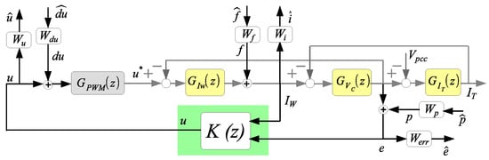
Figure 7.
Generalised plant of the single-loop voltage control for the grid-side converter of a grid-forming WTG.
As commented before, the uncertainty must be “plugged in” the weights to obtain the optimal controller:
- is the reference weight, considering that the system is scaled to pu values. The weight is a constant, and it is fixed to 1 to ensure reference shaping, as in the prior designs;
- is the weight of a perturbation at the control action. This weight is fixed to 0.01, considering a 1% perturbation at the input. In this design, is lower than the previous designs because now the complete model (LC filter plus WTG transformer) has been considered, not just the L transfer function ;
- is a weight of perturbation at the current . This weight is fixed to 0.02, considering a 2% perturbation at the current;
- is the control action weight. This weight is fixed to 0.2 to allow the controller to apply an increment of 5 at the control action (this means 1.1 volts per each required volt, in absolute value);
- is the current weight. This weight is unnecessary but is introduced to limit the current dynamics. This weight is fixed to 0.02;
- is the voltage error weight. This weight assumes the same consideration as the weights and for the previous controllers. Hence, this weight is also tuned to achieve a closed-loop norm less than 1. The resulting values of , and from for this weight are listed in Table 5.
Table 5.
Weight parameters of the single-loop voltage control.
The selected weights used for the controller synthesis are shown in Figure 8.
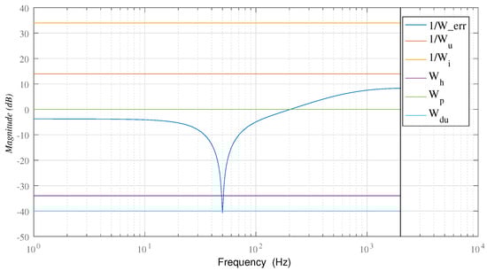
Figure 8.
Weights for design of the single-loop voltage control.
Equation (20) shows the obtained controller. Table 5 shows the used weights in the generalised plant that allow the controller synthesis using Matlab’s hinfsyn function. The selected weights achieve closed-loop norm less than 1. This implies that the frequency responses of all outputs from the generalised plant remain below the inverse of their corresponding weights for a disturbance input spectrum below the specified weights in the generalised plant.
The obtained cascade controller is composed of a voltage and a current controller:
4. Results
This section compares the four controllers in terms of performance and robustness. The section compares the selected controllers in a realistic scenario, with the system model described in Section 2. This comparison has been carried out using a detailed electromagnetic transient (EMT) simulation of the system described in Section 2. The results are analysed regarding dynamic response and relevant voltage and current harmonics present in the system with each considered controller.
4.1. Design Results
Figure 9 illustrates the frequency response of the three designed controllers and the benchmark controller. The single voltage controller has a bigger gain for low frequencies, lower resonant peak and lower frequency gain than the other controllers. The current frequency response of a single voltage controller is lower for all frequencies without any resonant peak.
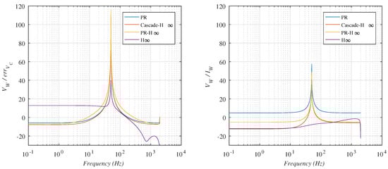
Figure 9.
Frequency response of the designed controllers (left: ; right: ).
To analyse the response of the controllers and their robustness, the designed controllers have been tested in three different scenarios, namely open-circuit islanded WTG, islanded WTG with rated-load and WTG connected to an ideal grid (DR-connected).
Figure 10 shows the response of the designed controllers to a unit sinusoidal reference in the three considered scenarios (ISL no-load, ISL with rated-load and DR-connected).
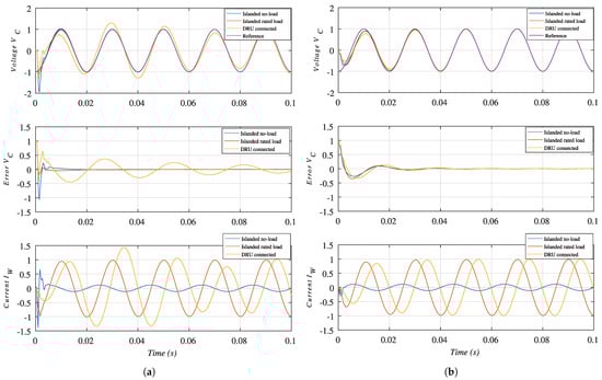
Figure 10.
Voltage and current result in the model used for design. The current is scaled with a 0.3 factor in the case of DR-connected. (a) Cascaded controller. (b) voltage controller.
It has been found that the time response of the three cascaded controllers is very similar. Therefore, only the response of the controller is shown for clarity. The cascaded controllers have a faster response in the islanded scenarios. Still, when the WTG is connected to the DR (similar to connecting to a grid with a low impedance), the cascaded controller achieves a settling time of 200 ms.
In the case of the voltage controller, the response in the three scenarios is very similar.
An a posteriori analysis, using the normalised coprime factor uncertainty margin [], shows the robustness level of the designs to the considered parametric uncertainties.
Table 6 shows the achieved margins for the designed controllers. The voltage controller can be considered the most robust, as it achieves better margins for islanded no-load and grid-connected operation, and almost the same margin for islanded rated-load operation, than the cascaded controller.
Table 6.
Normalised coprime factor uncertainty margin.
4.2. EMT Simulation Results
The performance of the obtained controllers is validated in the described system in Section 2 using a detailed EMT simulation. Figure 11 shows the simulation results considering the -tuned cascaded PR controller and the full controller. Note that the -tuned PR is the only cascaded controller shown, as the results for the other two cascaded controllers (root locus PR and cascaded ) are very similar to the results shown in Figure 11a).
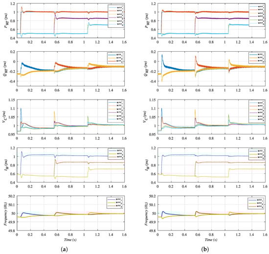
Figure 11.
Detailed EMT simulation of the DR-based off-shore WPP. (a) PR cascaded controller. (b) controller.
To compare both current controller designs, changes in active power references are applied to each off-shore WPP. The changes in active power reference are ramped up, considering a ramp of 12.5 ms. Such a large slope is not realistic in practice, but it illustrates the behaviour of the different current controllers.
From top to bottom, the first graph in Figure 11 shows the active power delivered by each WPP cluster, together with its reference. The second graph shows the reactive power being delivered by each WPP cluster. The third graph shows the WTG capacitor voltage () and its reference. The fourth graph shows the current magnitude of (), and the frequency of each WPP cluster is shown in the fifth graph.
Both controllers obtain a similar dynamic response because the outer droop control (see Figure 2) dominates the system dynamics. However, the cascaded voltage converter causes a higher overshoot in active power response. Moreover, the controller tracks the reference capacitor voltage much better.
Additionally, the active power response coupling between each WPP cluster is more negligible when using the full controller.
It is worth pointing out that the current is higher than 1 pu for part of the transient. This is caused by the fact that is required to supply 1 pu active power while contributing to the reactive power requirements of the overall off-shore grid. Therefore, the overall current magnitude is slightly higher than 1 pu.
Voltage, current and reactive power ripple are the same for both cascaded controllers and full controllers. A comparative analysis shows the harmonic rejection capabilities of the designed controllers through a quantitative examination of voltage and current harmonic contents.
Table 7 shows the 11th and 13th voltage and harmonic contents for each one of the considered controllers. The analysis has been carried out using Fourier analysis of the detailed EMT simulation results, considering the output power of each WPP cluster being pu, pu and pu, as at the end of the first graph of Figure 2.
Table 7.
Main voltage and current harmonic of the DR-based WPP.
The 11th and 13th harmonics have been selected, as they are the characteristic harmonics of the 12-pulse HVdc diode rectifier converter.
The root locus-based PR controller offers the worst 11th and 13th voltage and current harmonic components of the four considered controllers. The other two cascaded controllers (PR and cascaded ) somehow show improved voltage and harmonic contents, both with very similar figures for 11th and 13th voltage and current harmonic components.
On the other hand, the full controller shows substantially reduced voltage and harmonic components.
All the shown results show that voltage and current performances improve using controllers based on synthesis. Moreover, active and reactive power performance also improve, especially when using the single-voltage controller, as shown in the DR-based WPP results.
To summarise, controllers optimised using design techniques show better performance than their root locus counterparts, not only for controllers with different orders but also for controllers with the same order (-tuned PR). Not surprisingly, the full control performs better than the other three controllers.
5. Discussion and Conclusions
This paper presents a methodology to design three different voltage controllers, using techniques with a resonant behaviour for grid-forming converters.
The techniques use both cascaded controller design and a voltage controller without an inner current loop. Additionally, techniques are used to improve the performance and robustness of the cascaded control based on PR regulators via a structured PR design, which allows for a fair comparison between structured PR controllers, cascaded controllers and direct controllers.
The controllers have been designed by considering the islanded no-load plant, which produces adequate results in islanded rated-load and DR-connected modes of operation.
The paper provides directives for the input and output weights’ selection to synthetise the controllers, considering the system’s unstructured uncertainty and the controllers’ desired performance. The obtained controllers using synthesis improve the performance, robustness and harmonic rejection in comparison with the controller achieved using classical control design techniques (root locus).
The dynamic response of all controllers has been tested for the three considered operating modes (islanded no-load, islanded rated-load and DR-connected): first of all, considering a sinusoidal reference, and, secondly, as part of a detailed simulation of the complete WPP and the HVdc diode rectifier link.
The dynamic response to a sinusoidal reference of all the controllers is reasonable for the islanded no-load condition (this is the plant used for all controller designs). However, the cascaded controllers’ performance shows worse dynamics than the single controller when changing the mode of operation, particularly for the DR-connected case.
Concerning robustness, coprime factor uncertainty margins are better using controllers than using PR based on root locus design, as expected. Within the controllers, the best coprime factor uncertainty margin is shown by the single design. The single optimisation has no structural constraints in its design, at the expense of requiring more complicated current-limiting techniques than cascaded designs.
Finally, the detailed EMT simulations of the complete system show that, even though all considered controllers’ responses are reasonable, the controller shows the best dynamic performance of all controllers, with the lowest voltage and current harmonic distortion.
It has been shown that all -based controllers offer better performance than the standard root locus-designed PR controller, with the best performance being obtained by the single controller. Therefore, even when considering a fixed PR structure, design offers clear advantages for the design of the voltage control of grid-forming converters.
This work paves the way for further optimisation considering different grid configurations, which is particularly relevant for grid-forming converters used in DR-based off-shore WPPs, including the black-start operation of these WPPs. In this kind of WPP, the uncertainty is limited and can be easily bounded. This is important because large uncertainty can produce controllers with poor performance that are too conservative.
Author Contributions
Conceptualisation, J.M.-T. and R.B.-G.; methodology, R.B.-G. and A.S.; software, J.M.-T. and A.S.; validation, J.M.-T., A.S. and C.B.; formal analysis, J.M.-T. and A.S.; investigation, J.M.-T. and A.S.; resources, J.M.-T. and C.B.; data curation, J.M.-T. and C.B.; writing—original draft preparation, J.M.-T. and A.S.; writing—review and editing, R.B.-G. and A.S.; visualisation, J.M.-T. and A.S.; supervision, J.M.-T. and R.B.-G.; project administration, R.B.-G.; funding acquisition, R.B.-G. All authors have read and agreed to the published version of the manuscript.
Funding
Authors would like to acknowledge the support of the Spanish Research Agency through grant PID2020-112943RB-I00 funded by MCIN/AEI/10.13039/501100011033 and grant PDC2021-121077-I00 funded by MCIN/AEI/10.13039/501100011033 and by the European Union NextGenerationEU/PRTR.
Institutional Review Board Statement
Not applicable.
Informed Consent Statement
Not applicable.
Data Availability Statement
Data is contained within the article.
Conflicts of Interest
The authors declare no conflicts of interest.
Abbreviations
The following abbreviations are used in this manuscript:
| HVdc | High-Voltage Direct Current |
| DR | Diode Rectifier |
| WPP | Wind Power Plant |
| VSC | Voltage Source Converter |
| WTG | Wind Turbine Generator |
| PWM | Pulse Width Modulation |
| MMC | Modular Multilevel Converter |
| SCR | Short Circuit Ratio |
| PI | Proportional Integral |
| ZOH | Zero-Order Hold |
| ISL | Islanded |
| PCC | Point of Common Coupling |
Appendix A
Table A1 shows the parameter values of the system components.
Table A1.
System Parameters.
Table A1.
System Parameters.
| Wind Turbines | |
|---|---|
| Grid-side converter: | 8 MW; 1.2 kVcc; 690 Vac; 50 Hz |
| Grid-side filter: | ; H; F |
| Transformer: | 9.2 MVA; 0.69/66 kV; pu; pu; Saturable |
| Off-Shore ac Grid | |
| WTG to WTG distance: | 2 km |
| WTG to ring-bus distance: | 4 km |
| Distance between platforms: | 10 km |
| String cable sections: | C = 150 mm; B = 185 mm; A = 400 mm |
| String with 8 WTGs: | C-C-B-B-B-B-B-A |
| String with 9 WTGs: | C-C-B-B-B-B-B-A-A |
| DR Platform | |
| DR filter: | Filter and compensation filter bank according to [] |
| Transformer: | 215 MVA; 66/43/43 kV; pu; pu |
| dc-smoothing reactor: | 66.67 mH |
References
- Aten, M.; Werner, H. Robust multivariable control design for HVDC back to back schemes. IEE Proc.-Gener. Transm. Distrib. 2003, 150, 761–767. [Google Scholar] [CrossRef]
- Rigatos, G.; Siano, P.; Cecati, C. A new non-linear H-infinity feedback control approach for three-phase voltage source converters. Electr. Power Compon. Syst. 2016, 44, 302–312. [Google Scholar] [CrossRef]
- Blasco-Gimenez, R.; Añó-Villalba, S.; Rodríguez-D’Derlée, J.; Morant, F.; Bernal-Perez, S. Distributed Voltage and Frequency Control of Offshore Wind Farms Connected with a Diode-Based HVdc Link. IEEE Trans. Power Electron. 2010, 25, 3095–3105. [Google Scholar] [CrossRef]
- Menke, P. New grid access solutions for offshore wind farms. EWEA Off-Shore 2015. [Google Scholar]
- Seman, S.; Zurowski, R.; Christ, T. Investigation of DC Converter Nonlinear Interaction with Offshore Wind Power Park System. EWEA Off-Shore 2015. [Google Scholar]
- Christ, T.; Seman, S.; Zurowski, R. Power Generation Facility and Method for the Operation Thereof. U.S. Patent App. 15/741,777, 2018. [Google Scholar]
- Bouzid, A.; Chériti, A.; Sicard, P. H-∞ loopshaping controller design of micro-source inverters to improve the power quality. In Proceedings of the 2014 IEEE 23rd International Symposium on Industrial Electronics (ISIE), Istanbul, Turkey, 1–4 June 2014; pp. 2371–2378. [Google Scholar] [CrossRef]
- Li, Z.; Zang, C.; Zeng, P.; Yu, H.; Li, S.; Bian, J. Control of a Grid-Forming Inverter Based on Sliding-Mode and Mixed H_2/H_ınfty Control. IEEE Trans. Ind. Electron. 2017, 64, 3862–3872. [Google Scholar] [CrossRef]
- Yu, L.; Li, R.; Xu, L. Distributed PLL-Based Control of Offshore Wind Turbines Connected with Diode-Rectifier-Based HVDC Systems. IEEE Trans. Power Deliv. 2018, 33, 1328–1336. [Google Scholar] [CrossRef]
- Huang, L.; Xin, H.; Dörfler, F. H∞-Control of Grid-Connected Converters: Design, Objectives and Decentralized Stability Certificates. IEEE Trans. Smart Grid 2019, 11, 3805–3816. [Google Scholar] [CrossRef]
- Watson, J.D.; Ojo, Y.; Laib, K.; Lestas, I. A Scalable Control Design for Grid-Forming Inverters in Microgrids. IEEE Trans. Smart Grid 2021, 12, 4726–4739. [Google Scholar] [CrossRef]
- Farrokhseresht, N.; van der Meer, A.A.; Rueda Torres, J.; van der Meijden, M.A.M.M. MOSAIK and FMI-Based Co-Simulation Applied to Transient Stability Analysis of Grid-Forming Converter Modulated Wind Power Plants. Appl. Sci. 2021, 11, 2410. [Google Scholar] [CrossRef]
- Martínez-Turégano, J.; Sala, A.; Blasco-Gimenez, R. Grid forming H∞ control for HVDC diode rectifier-connected wind power plants. CSEE J. Power Energy Syst. 2023, 1–13. [Google Scholar]
- Almutairi, S.Z. Dynamic Interactions between Parallel Grid-Forming Inverters in a Microgrid. Appl. Sci. 2023, 13, 6989. [Google Scholar] [CrossRef]
- Wang, K.; Song, Q.; Zhao, B.; Yu, Z.; Zeng, R. Grid-Forming Control of Offshore Wind Farms Connected with Diode-Based HVdc Links based on Remote Active Power Regulation. IEEE Trans. Sustain. Energy 2023, 1–13. [Google Scholar] [CrossRef]
- Yu, L.; Miao, S.; Zhu, J.; Fu, Z.; Li, R.; Zhao, C. Self-synchronization control of offshore wind turbines connected with DRU-HVDC. CSEE J. Power Energy Syst. 2023, 1–11. [Google Scholar]
- Zhou, K.; Doyle, J.C. Essentials of Robust Control; Prentice Hall: Upper Saddle River, NJ, USA, 1998; Volume 104. [Google Scholar]
- Skogestad, S.; Postlethwaite, I. Multivariable Feedback Control: Analysis and Design; Wiley: New York, NY, USA, 2007; Volume 2, p. 07543. [Google Scholar]
- Martínez-Turégano, J.; Añó-Villalba, S.; Bernal-Perez, S.; Blasco-Gimenez, R. Aggregation of Type-4 Large Wind Farms Based on Admittance Model Order Reduction. Energies 2019, 12, 1730. [Google Scholar] [CrossRef]
- Martínez-Turégano, J.; Añó-Villalba, S.; Bernal-Perez, S.; Peña, R.; Blasco-Gimenez, R. Small-signal stability and fault performance of mixed grid forming and grid following offshore wind power plants connected to a HVDC-diode rectifier. IET Renew. Power Gener. 2019, 14, 2166–2175. [Google Scholar] [CrossRef]
- Guerrero, J.M.; Vicuna, L.G.d.; Matas, J.; Castilla, M.; Miret, J. Output impedance design of parallel-connected UPS inverters with wireless load-sharing control. IEEE Trans. Ind. Electron. 2005, 52, 1126–1135. [Google Scholar] [CrossRef]
- Vasquez, J.C.; Guerrero, J.M.; Savaghebi, M.; Eloy-Garcia, J.; Teodorescu, R. Modeling, Analysis, and Design of Stationary-Reference-Frame Droop-Controlled Parallel Three-Phase Voltage Source Inverters. IEEE Trans. Ind. Electron. 2012, 60, 1271–1280. [Google Scholar] [CrossRef]
- Teodorescu, R.; Blaabjerg, F.; Liserre, M.; Loh, P.C. Proportional-resonant controllers and filters for grid-connected voltage-source converters. IEE Proc.-Electr. Power Appl. 2006, 153, 750–762. [Google Scholar] [CrossRef]
- Teodorescu, R.; Liserre, M.; Rodriguez, P. Grid Converters for Photovoltaic and Wind Power Systems; John Wiley & Sons: Hoboken, NJ, USA, 2011. [Google Scholar]
- Cóbreces, S.; Wang, X.; Pérez, J.; Griñó, R.; Blaabjerg, F. Robust Admittance Shaping Approach to Grid Current Harmonic Attenuation and Resonance Damping. IEEE Trans. Ind. Appl. 2018, 54, 5039–5053. [Google Scholar] [CrossRef]
- Szechtman, M.; Wess, T.; Thio, C.V. First benchmark model for HVDC control studies. Electra 1991, 135, 54–73. [Google Scholar]
Disclaimer/Publisher’s Note: The statements, opinions and data contained in all publications are solely those of the individual author(s) and contributor(s) and not of MDPI and/or the editor(s). MDPI and/or the editor(s) disclaim responsibility for any injury to people or property resulting from any ideas, methods, instructions or products referred to in the content. |
© 2024 by the authors. Licensee MDPI, Basel, Switzerland. This article is an open access article distributed under the terms and conditions of the Creative Commons Attribution (CC BY) license (https://creativecommons.org/licenses/by/4.0/).