Communication

A Multiple-Cantilever Piezoelectric Vibration Energy Harvester for Self-Powered CO2 Monitoring in Transformer Substations

1
State Key Laboratory of Technology and Equipment for Defense Against Power System Operational Risks, Nanjing 211106, China
2
Jiangsu Key Lab of Remote Measurement and Control, School of Instrument Science and Engineering, Southeast University, Nanjing 210096, China
3
Institute of Biomedical Devices, Southeast University, Suzhou 215163, China
*
Author to whom correspondence should be addressed.
Appl. Sci. 2024, 14(23), 10805; https://doi.org/10.3390/app142310805
Submission received: 3 October 2024 / Revised: 17 November 2024 / Accepted: 20 November 2024 / Published: 22 November 2024

Abstract

:
The long-term CO2 emissions of transformer substations require constant monitoring. In this study, we propose a piezoelectric vibration energy harvester designed for self-powered CO2 monitoring of transformer substations. The proposed harvester comprises multiple slender piezoelectric cantilevers arranged in parallel, which results in a higher operational frequency and a significantly enhanced power output capability. Experimental investigations were conducted to assess the energy harvesting performance. The results show that the harvester can effectively capture the vibration energy, yielding an RMS power output of 2.99 mW, corresponding to the operational frequency of the transformer substation. Additionally, a wireless CO2 sensor node was developed, demonstrating an operational mechanism for CO2 monitoring. The capacitor takes approximately 1220 s to charge for the initial data measurement and transmission. The findings confirm that the energy harvester is capable of providing sufficient power to operate the sensor node for CO2 monitoring in transformer substations.

1. Introduction

Building construction and electricity transportation contribute the majority of carbon emissions. With the aim of carbon neutrality and carbon compliance, it becomes critical to monitor distributed carbon emissions of the key nodes of electricity transportation, i.e., monitoring the carbon emissions of transformer substations. With the growth of the Internet of Things (IoT) and environmental energy harvesting, self-powered wireless sensors have received significant attention [1,2,3,4,5,6,7,8,9,10,11,12,13]. Mechanical vibrations are continuously available at transformer substations with constant operational frequencies of 100 Hz [14,15,16], thus providing a large amount of reliable renewable energy to power sensor nodes without additional carbon emissions. Piezoelectric energy harvesting has the advantages of a simple structure and high efficiency for harvesting electrical energy from vibrations [5,6,7,8,9,10,11,12]. Typically, cantilever-based piezoelectric energy harvesters (PEHs) are employed to harvest the environmental vibration energy [17,18,19,20,21,22,23,24] and to be connected to power wireless sensor nodes [5,14,18,19].
In the early stages of research in this area, Roundy observed that a piezoelectric transducer experiences an uneven strain distribution along its longitudinal axis. To address this, he proposed that a trapezoidal beam would exhibit a more uniform strain distribution, potentially doubling the energy output compared to conventional designs, with the goal of optimizing the shape of the energy harvester [25]. This concept of strain smoothing subsequently garnered significant attention in the literature [26,27,28,29]. In addition, adopting advanced materials would also enhance the efficiency of vibration energy harvesting [30]. A non-resonance piezoelectric energy harvester was also proposed to achieve a robust performance at different frequency points [31]. In subsequent years, significant efforts were directed towards broadening the bandwidth of energy harvesters. Several innovative mechanisms were proposed, including Duffing oscillator-based nonlinearities [32,33], segmental stiffness [34], internal resonance [35,36,37,38], multimodal configurations [39], and frequency up-conversion mechanisms [40,41]. Notably, Duffing-type piezoelectric energy harvesters (PEHs) incorporating permanent magnets have demonstrated large amplitude voltage outputs over a wide frequency range when subjected to large amplitude excitations [42,43,44,45,46,47]. More recently, Duffing-type PEHs with multiple small, stable, and flexible potential barriers have been designed to optimize their performance under low-amplitude excitations [48,49,50,51,52].
The aforementioned PEHs were designed and optimized for general applications. In contrast, the mechanical vibrations in a transformer substation exhibit a constant operational frequency of 100 Hz in China and Europe, or 120 Hz in the US [14,15,16]. Slender piezoelectric cantilevers are typically used in these applications, because they can generate significant strain on their surface, effectively converting mechanical energy into electrical energy through the 1–3 electromechanical coupling effect. In contrast, thick beams and thick piezoelectric materials tend to experience large shear strains in the epoxy resin bonding layer, which significantly reduces the efficiency of the PEH. However, typical slender piezoelectric cantilevers exhibit low resonant frequencies [21,22,23,24,25,26,27,28,29], which limits their applicability in harvesting mechanical energy from transformer substations. Moreover, it is important to note that a single piezoelectric transducer has a limited power output due to the inherent strain and voltage constraints of its design. Increasing the number of piezoelectric transducers, particularly by employing multiple slender cantilevers, offers a promising solution to these limitations.
In this research, we introduce a novel multiple-cantilever piezoelectric vibration energy harvester designed for self-powered CO2 monitoring in transformer substations. The system features slender piezoelectric cantilevers arranged in parallel, with connectors at both the fixed and free ends, facilitating an S-shaped bending mode of vibration. This innovative design offers several advantages. The assembly of multiple cantilevers and the S-shaped bending mode significantly boost the resonant frequency of the PEH system, aligning it with the operational frequency of transformer substations. Furthermore, the integration of multiple piezoelectric transducers substantially enhances the system’s power output capacity. To validate the proposed PEH, a self-powered wireless sensor node has been developed for assessing its performance in CO2 monitoring within the context of transformer substations.
The remainder of this paper is organized as follows: the system configuration is presented in Section 2. Experimental studies and discussions of the system for self-powered CO2 monitoring are presented in Section 3. Finally, the conclusions are provided in Section 4.

2. System Design

The self-powered sensor node for CO2 monitoring within transformer substations, along with the prototype of the proposed piezoelectric energy harvester, is depicted in Figure 1. The self-powered sensor node comprises a multiple-cantilever PEH, a microcontroller-based sensor node equipped with a CO2 sensor module, and a wireless module, as illustrated in Figure 2. Additionally, the multi-layer piezoelectric cantilever system is composed of three identical piezoelectric beams that are stacked vertically. A proof mass is affixed to the free end of the multi-layer PEH to fine-tune its resonant frequency. This PEH is subjected to excitation in the vertical direction.
The key advantage of the proposed PEH comes from the multiple-layer configuration of the cantilever. Multiple piezoelectric cantilevers are assembled to enhance the resonant frequency of the PEH. In addition, the S-shape vibration mode is also shown in Figure 1b. The vibration mode was obtained using a Finite Element Method (FEM) simulation using COMSOL Multiphysics 6.1. In the FEM analysis using COMSOL, hexahedron element and linear element orders were used. The COMSOL model consisted of three 75.18 × 20 × 0.16 mm3 stainless steel cantilevers. Six PZT-5H piezoelectric transducers with identical dimensions of 15 × 20 × 0.2 mm3 were glued at the root and free end of the cantilevers. A magnetite-based proof mass was introduced to provide additional constraints for the bending of the three beams. A fixed constraint was added on the base of the fixed end of the cantilever beam as the boundary condition. The modal shape of the beam was evaluated through Eigenfrequency analysis.
It can be seen that each section of the cantilever is undergoing an S-shaped bending motion, as shown in Figure 2. The proof mass introduced additional constraints, ensuring that the free ends of the cantilevers experienced no rotation, which would result in significant bending moments. Hence, the torques in the longitudinal direction of the piezoelectric cantilever were decreased to zero and then increased from the free end to the fixed end of the beam. In other words, both the fixed and free ends of the beam undergo strain concentrations. As a result, piezoelectric transducers were mounted at the tip of the beam. This would further increase the system-level stiffness of the cantilever, thereby raising the resonant frequency to match that of the transformer substation. Piezoelectric transducers can be attached at both the fixed and free end of the beam to increase the power output.

3. Experimental Studies and Discussions

3.1. Experimental Setup

The experimental setup of the proposed multiple-layer PEH is shown in Figure 3. In this research, we mainly focused on illustrating the features of the proposed harvester experimentally. Ghodsi developed a detailed analytical electromechanical coupling model in Ref. [31]. The PEH contained three piezoelectric cantilevers with connections at both the fixed and free ends. The spring steel substrate of the piezoelectric cantilever had dimensions of 75.18 × 20 × 0.16 mm3. Six piezoelectric transducers (15 × 20 × 0.2 mm3) were glued to the root and free end of the cantilevers using epoxy resin DP460 (3M, St. Paul, MN, USA). The lead zirconate titanate-5 piezoelectric transducers were purchased from Jiayeda, Co., Ltd., Changde, China, with Young’s Modulus of 106 GPa and piezoelectric coefficient d31 = −171 pC/N. The proof mass was attached at the free end of the PEH. The proof mass was made of permanent magnet blocks. Permanent magnets were glued onto the cantilever as the primary proof mass. Additional permanent magnets were attached to the primary one to tune the natural frequency of the harvester to the operational frequency of 100 Hz. As the permanent magnets would provide attractive force to each other, the additional permanent magnets were added to the fixed location at the free end of the cantilever. The number and sizes of the magnets were carefully selected to adjust the resonant frequency of the model to 100 Hz. A 200 N shaker was adopted to provide the base-movement excitations. The root mean square (RMS) output voltages of the piezoelectric transducers were measured by a NI-DAQ device (PCIe6343) (National Instruments, Austin, TX, USA) with a sampling frequency of 20 kHz. In addition, the amplitude of the base-movement was measured by an accelerometer.
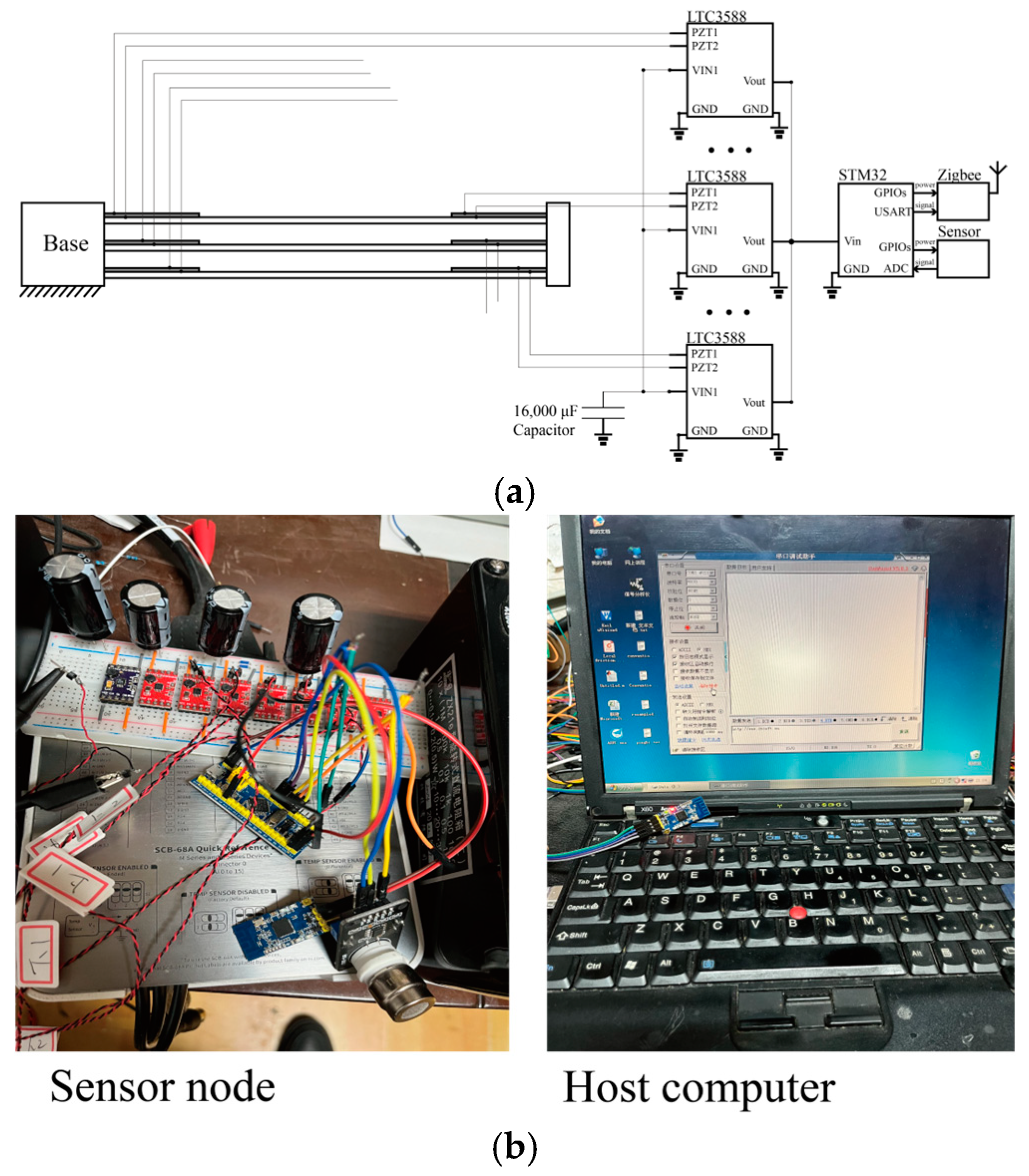
In order to validate the performance of the self-powered CO2 monitoring, a self-powered wireless sensor node was designed consisting of an STM32F103C6 microcontroller (STMicroelectronics, Geneva, Switzerland), an analog CO2 sensor, a Zigbee wireless module CC2530 (Texas Instruments, Dallas, TX, USA), six LTC-3588 voltage rectifications/regulators (Sparkfun, Boulder, CO, USA), and energy storage capacitors, as shown in Figure 3. The LTC-3588 was proven to have good performance for rectifying and regulating the output voltages from piezoelectric transducers [31]. It outputs 3.3 V to power the microcontroller, sensor, and Zigbee wireless modules. In Figure 3, three LTC3588s are drawn in the sketch due to the space limitation of the figure. The other ones are represented by ellipses. To guarantee a sufficient and stable power supply for the wireless sensing node during operation, this study employed 16,000 μF capacitors for energy storage. A microcontroller was used to manage the sensor and Zigbee module, with its clock frequency set to 16 MHz to minimize the overall power consumption. Opting for a low-power microcontroller, such as the STM32L or Attiny85 (Microchip Technology, Chandler, AZ, USA), could further decrease the power usage of the sensor node. An ADC port was selected to retrieve the analog signal from the CO2 sensor. Acknowledging that the wireless module and the sensor are the primary consumers of electrical energy in the circuit, we designed the power supply to these modules through multiple GPIO ports, which have the capability to be shut down instantaneously to conserve energy. The receiver, a secondary CC2530 Zigbee module, and a laptop were included in the host computer, as shown in Figure 4b. Typically, the Zigbee wireless data transmission module can have a theoretical communication distance of up to 250 m outdoors. In the experiment, the receiver was placed in the vicinity of the wireless sensor node for the conceptual illustration. The proposed system, excluding an antenna of the wireless transmission module, would be enclosed in a shielding box to prevent the electromagnetic disturbance of a transformer substation.

3.2. Voltage and Power Output Performance

In this section, we evaluate the frequency responses of the voltage and power output of the proposed multiple-cantilever PEH. Noting that a power transformer substation has a primary operational frequency of 100 Hz [8,9,10,11], the performances of the PEH were evaluated close to this frequency value. Base-movement excitations with a constant amplitude of acceleration were provided by an electromagnet shaker and controlled by an acceleration meter, as previously illustrated in Figure 3. It was illustrated experimentally that a Three-Phase Three-Leg Core with a 142 mm ribbon, which was 142 mm wide and had a 60 mm lamination thickness of its core, would yield vibration with amplitudes up to 1.5~4 g [53]. Therefore, the acceleration values of excitations were chosen as 0.373~2.98 g, which are common values in real applications [53].
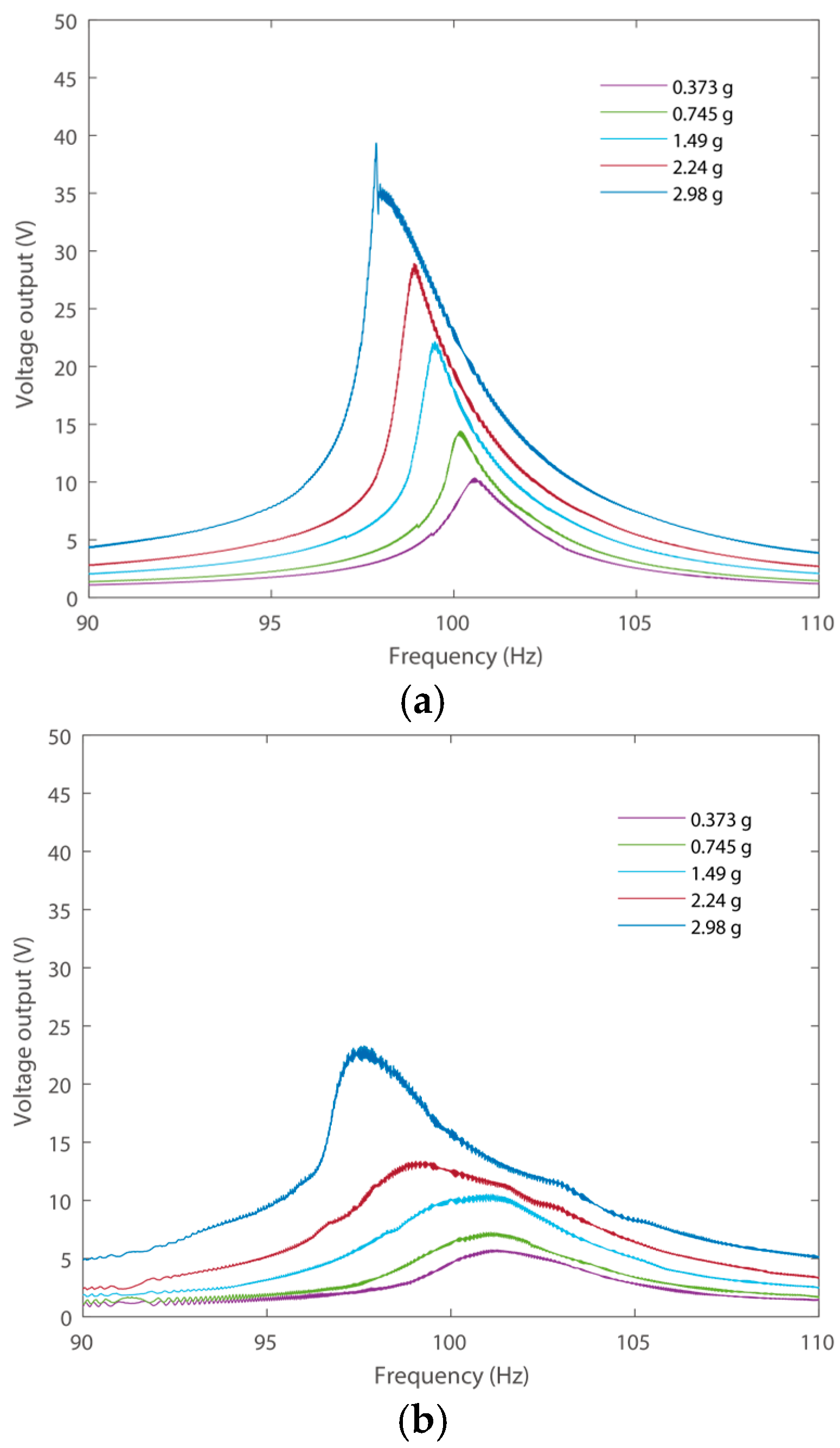
Figure 5 shows the open circuit voltage output under forward and backward frequency sweeping. The voltage outputs of the piezoelectric transducer on the first layer at the fixed end (PZT1) under excitations with different amplitudes are presented for illustration. The forward frequency responses are shown in Figure 5a, where the frequencies of excitations sweep from low to high. It can be seen that the harvester reached its RMS open circuit voltage output of 14.28 V under 0.745 g amplitude excitation in the forward frequency responses, as shown in Figure 5a. An increase in the amplitudes of excitation can effectively enhance the voltage outputs. For instance, the peak output of the PEH is 29.17 V under an excitation of 2.98 g. Additionally, the proposed PEH exhibits a softening effect under a large amplitude excitation of 2.98 g, i.e., the voltage outputs lean towards the left under a large amplitude excitation with a sudden decrease at 98.88 Hz in the forward frequency sweeping. This phenomenon can be attributed to the nonlinearity of the additional constraints, which led to uneven stress in the three beams, since the three cantilevers are assembled in parallel. In addition, the backward frequency responses are shown in Figure 5b, where the frequencies of excitations sweep from high to low. The frequency responses under forward and backward responses show difference with each other due to the exitances of nonlinearity. The voltage outputs in this scenario are smaller than those under forward frequency sweeping. The high voltage output can be achieved by properly selecting the frequency sweeping direction in a real application. Additionally, an increase in the amplitudes of excitation can effectively enhance the voltage outputs. Nevertheless, the PEH has large amplitude voltage outputs around 100 Hz that could power the wireless sensor node.
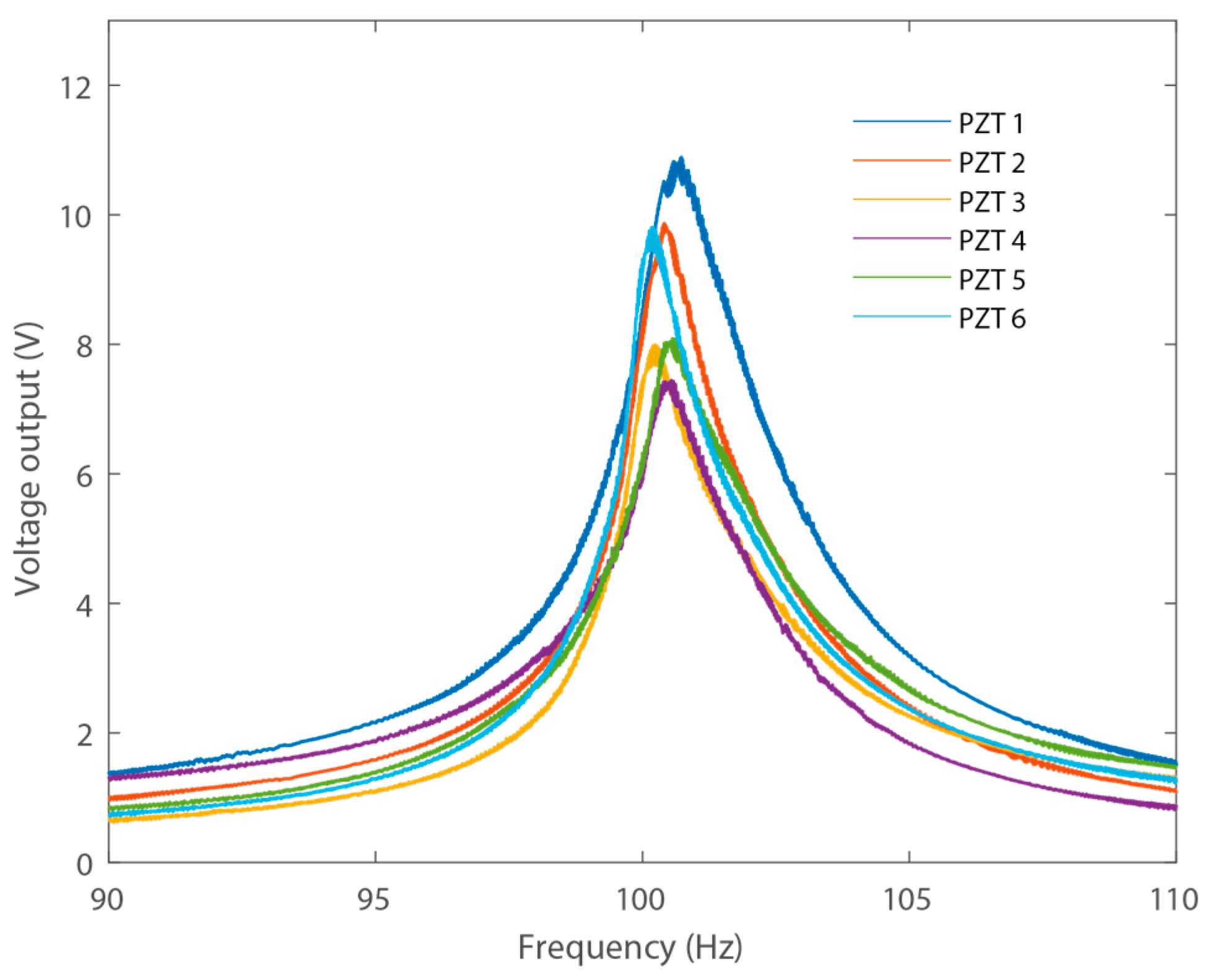
As the proposed PEH contains six piezoelectric transducers, the open circuit RMS voltages of all the transducers were measured and compared, as shown in Figure 6. The voltage outputs were measured under excitations of 0.745 g. In addition, the voltage outputs of different piezoelectric transducers exhibited minor differences with each other. These stem from the various material properties of the transducers, as well as manual assembly errors. In addition, it can be observed that the transducers attached to the same cantilever have similar voltage outputs. In practice, these outputs are influenced by material properties and the adhesive bonding process. Specifically, the piezoelectric transducers sourced from Jiayeda exhibit slight variations in their piezoelectric and dielectric constants, leading to differences in their voltage outputs in this experiment. Nevertheless, all the piezoelectric transducers can effectively output electrical energy.
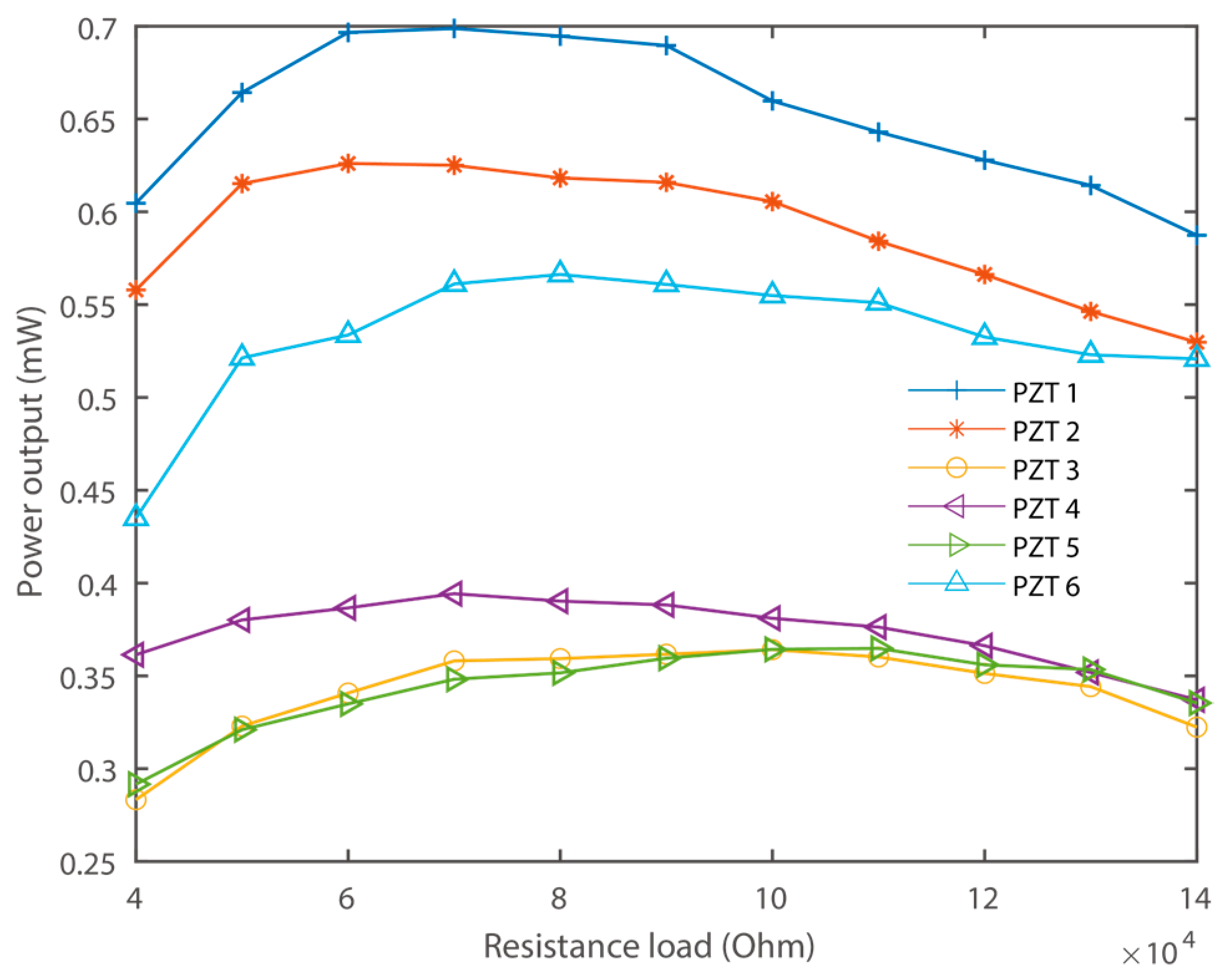
To evaluate the power output capability of the proposed PEH, each of the piezoelectric transducers were connected to individual resistance loads [32,33,34,35]. The power output responses were measured under a constant excitation of 0.745 g, with different resistance loads around 100 Hz. The resulting voltage across the load resistance was measured and recorded, as shown in Figure 7.
Figure 7 illustrates the relationship between the RMS output power and load resistance for the piezoelectric transducers, demonstrating that the optimal output power is contingent upon the specific resistance load. The transducers achieve their peak performance under their respective best-matching resistance loads, which are 70 kΩ, 60 kΩ, 100 kΩ, 70 kΩ, 100 kΩ, and 80 kΩ for each transducer. Correspondingly, the peak RMS power outputs are 0.69 mW, 0.63 mW, 0.36 mW, 0.39 mW, 0.36 mW, and 0.56 mW, respectively. Collectively, the piezoelectric transducers can deliver a total power output of 2.99 mW under these conditions. It is important to note that increasing the amplitude of the excitations can significantly boost the power output. It should be highlighted that the resistance loads were utilized to assess the power output capability. Although connecting the piezoelectric sheets to voltage-rectifying bridges and capacitors might diminish the output power, the proposed PEH still demonstrates significant potential to supply power to a wireless sensor node.

3.3. Self-Powered CO2 Monitoring

To validate the performance of the proposed PEH for self-powered CO2 monitoring, the designed wireless sensor node was connected to the output of one of the LTC-3588 power converters. A CO2 sensor and a Zigbee wireless transmission module were integrated. The data were transmitted wirelessly to a host computer. The host computer was powered on continuously to receive data at a random time point. Due to the limited energy output of the PEH, a control algorithm of the sensor node was designed, as shown in Figure 8.
The control algorithm of the self-powered wireless sensor node is shown in Figure 8. Note that the PEH provides limited electrical energy, and the STM32 microcontroller will be in stop mode most of the time. The microcontroller will wake up when the LTC-3588 outputs sufficient energy. Here, the wireless sensor node requires a 3.3 V power supply. Additionally, the LTC-3588 will output 3.3 V when the voltage in the energy storage capacitor is around 4.73~5.37 V according to the datasheet. Serial ports of the microcontroller were used to connect the wireless transmission module to the register. When there is sufficient energy in the capacitor, the procedures of CO2 measurement and wireless data transmission will be triggered. Firstly, the CO2 sensor will be powered on, and the data will be recorded. Then, the sensor will be shut down for power saving, and the wireless module will be powered on for the wireless data transmission. Note that the sensor and wireless data transmission modules will still consume energy when connecting to power sources, even if they are not in working conditions. Four GPIO ports were connected in parallel to power the sensor and wireless modules. The modulus will be completely shut down when sensing and data transmission tasks are not required. It is worth mentioning that multiple time delay functions were tested and integrated for the initialization and operation of the sensing and wireless transmission modules during the program debugging.
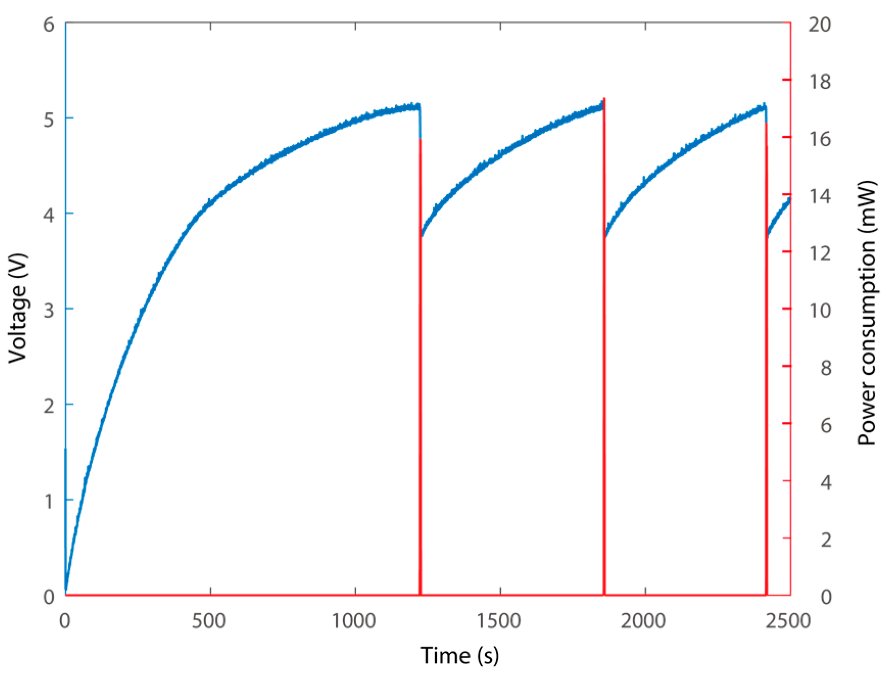
The self-powered wireless sensor node was connected to the capacitor of the vibration energy harvesting module under an excitation of 2.98 g. The electrical energy charging in the energy storage capacitor and the energy consumption of the wireless sensor node during discharge are described by measuring the voltage in the capacitor and the time of recharging, as shown in Figure 9. A typical excitation of a transformer substation is sinusoidal due to the constant operational frequency of the AC power line [53]. We can easily simulate the working conditions in the laboratory. Therefore, sinusoidal excitation was provided in this research to validate the proposed system conceptually under 2.98 g excitation.
Figure 9 shows the voltage of the capacitor, representing the process of charging, as well as the power consumption of the wireless sensor node. The charging process starts from a state of zero electrical energy storage in the capacitor. It can be deduced that it takes about 1220 s to charge the capacitor for the first data measurement and data transmission. It is worth noting that in a previous study, it took 8000 s to charge the capacitor and power a similar wireless sensor node with a single piezoelectric transducer PEH [40]. In other words, the advantages of multiple piezoelectric cantilevers with enhanced power output capabilities could be confirmed. In addition, a one-time recharging takes about 630 s in the following cycles. The voltage drop from 5.14 V to 3.76 V, which represents the power consumption of the processes of powering up, sensor data reading, and wireless data transmission. In this research, 16000 μF large capacitors were adopted, and thus, the wireless sensor node will consume 0.0983 J per sensing cycle, with a power consumption of 16~18mW. In addition, choosing a larger capacitor would provide more energy for each cycle of sensing and data transmission. And the energy storage capacitor starts charging again to enter the next cycle. Notably, the recharging time is sufficiently short for regular CO2 monitoring in a transformer substation. Notably, the time for recharging would be further shortened by reducing the power composition of the node.
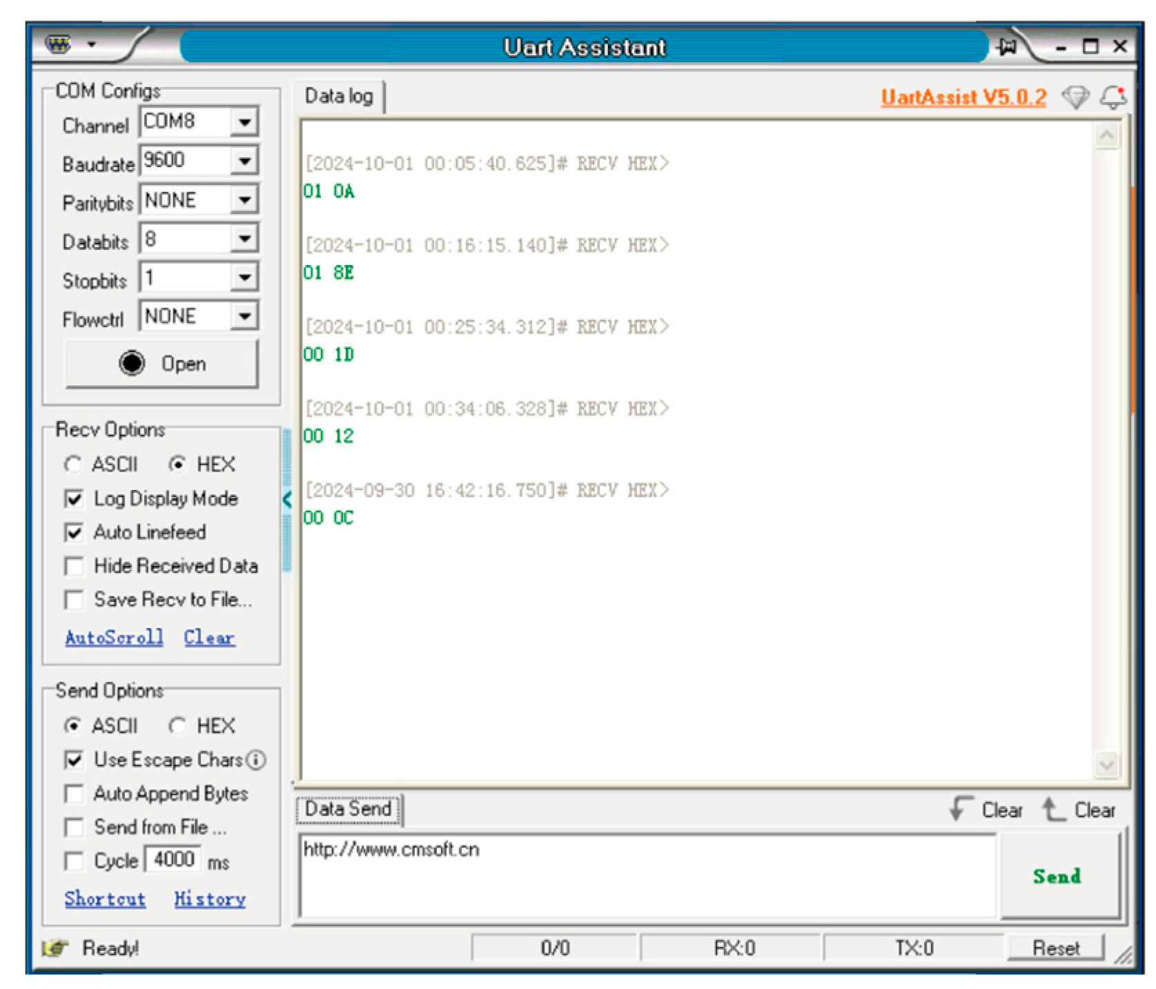
Figure 10 presents the interface on the host computer with the date of acquisition from the wireless sensor node. The transmitted data are the original hexadecimal read from the ADC port of the STM32 microcontroller. They indicate that the system can properly acquire and send data wirelessly. In the self-powered wireless sensor node, the powering up and CO2 measurement consume a much smaller amount of energy than that of data transmission, and the control algorithm can be optimized by increasing the number of data measurement processes while reducing the number of wireless data transmission procedures. It is worth mentioning that the designed wireless sensing node is a unit that is capable of edge computing and wireless communication, i.e., it consumes much more energy than a temperature–humidity meter or LED in previous studies. A more advanced power management algorithm can be further designed for optimal operation of the system for CO2 monitoring in transformer substations.

4. Conclusions

In this research, we proposed a multiple-cantilever piezoelectric vibration energy harvester and a wireless sensor node for CO2 monitoring in transformer substations. The harvester was assembled using multiple piezoelectric cantilevers working in S-shape vibration mode with enhanced power output capability. We demonstrated experimentally that the proposed PEH could harvest vibration energy at 100 Hz with a power output of 2.99 mW in total under 0.745 g excitation. In addition, voltage rectification and regulation modules were built, and a wireless sensor node was designed. The electrical energy generated by the harvester was injected into a capacitor, and the performances of power dissipation were demonstrated. It was shown that the system can effectively monitor CO2 with a power supply of the PEH with 1220 s required for the first charge and 630 s for recharging. The proposed energy harvesting and low-power wireless sensing node can be applied in remote CO2 monitoring in transformer substations.

Author Contributions

Conceptualization, L.C. and J.X.; methodology, L.C., M.Z., Z.X. and J.X.; validation, M.Z., Z.X., H.C. and J.X.; investigation, L.C., M.Z., Z.X. and J.X.; data curation, L.C., M.Z. and Z.X.; writing—original draft preparation, H.C.; writing—review and editing, J.X.; funding acquisition, L.C. and H.C. All authors have read and agreed to the published version of the manuscript.

Funding

This work was supported by the Open Foundation of State Key Laboratory of Technology and Equipment for Defense against Power System Operational Risks No. SGNR0000KJJS2302150, by the Jiangsu Frontier Leading Technology Fundamental Research Project under Grant No. BK20192004D.

Institutional Review Board Statement

Not applicable.

Informed Consent Statement

Not applicable.

Data Availability Statement

The raw data supporting the conclusions of this article will be made available by the authors on request.

Conflicts of Interest

The authors declare that they have no known competing financial interests or personal relationships that could have appeared to influence the work reported in this paper.

References

  1. Kim, H.S.; Kim, J.H.; Kim, J. A Review of piezoelectric energy harvesting based on vibration. Int. J. Precis. Eng. Manuf. 2011, 12, 1129–1141. [Google Scholar] [CrossRef]
  2. Mitcheson, P.D.; Yeatman, E.M.; Rao, G.K.; Holmes, A.S.; Green, T.C. Energy harvesting from human and machine motion for wireless electronic devices. Proc. IEEE 2018, 96, 1457–1486. [Google Scholar] [CrossRef]
  3. Paradiso, J.A.; Starner, T. Energy scavenging for mobile and wireless electronics. IEEE Pervasive Comput. 2005, 4, 18–27. [Google Scholar] [CrossRef]
  4. Priya, S. Advances in energy harvesting using low profile piezoelectric transducers. J. Electroceram. 2007, 19, 165–182. [Google Scholar] [CrossRef]
  5. Li, T.; Lee, P.S. Piezoelectric Energy Harvesting Technology: From Materials, Structures, to Applications. Small Struct. 2022, 3, 2100128. [Google Scholar] [CrossRef]
  6. Brusa, E.; Carrera, A.; Delprete, C. A Review of Piezoelectric Energy Harvesting: Materials, Design, and Readout Circuits. Actuators 2023, 12, 457. [Google Scholar] [CrossRef]
  7. Covaci, C.; Gontean, A. Piezoelectric Energy Harvesting Solutions: A Review. Sensors 2020, 20, 3512. [Google Scholar] [CrossRef]
  8. Sezer, N.; Koç, M. A comprehensive review on the state-of-the-art of piezoelectric energy harvesting. Nano Energy 2021, 80, 105567. [Google Scholar] [CrossRef]
  9. Nandish, M.B.; Hosamani, B. A Review of Energy Harvesting from Vibration using Piezoelectric Material. Int. J. Eng. Res. Technol. 2014, 3, 1607. [Google Scholar]
  10. Ballo, A.; Bottaro, M.; Grasso, A.D. A Review of Power Management Integrated Circuits for Ultrasound-Based Energy Harvesting in Implantable Medical Devices. Appl. Sci. 2021, 11, 2487. [Google Scholar] [CrossRef]
  11. Manbachi, A.; Cobbold, R.S.C. Development and Application of Piezoelectric Materials for Ultrasound Generation and Detection. Ultrasound 2011, 19, 187–196. [Google Scholar] [CrossRef]
  12. Clementi, G.; Cottone, F.; Di Michele, A.; Gammaitoni, L.; Mattarelli, M.; Perna, G.; López-Suárez, M.; Baglio, S.; Trigona, C.; Neri, I. Review on innovative piezoelectric materials for mechanical energy harvesting. Energies 2022, 15, 6227. [Google Scholar] [CrossRef]
  13. Wang, X.; Chen, Z.; Sun, W.; Shao, N.; You, Z.; Xu, J.; Yan, R. A Small Sample Piezoelectric Impedance-based Structural Damage Identification using Signal Reshaping-based Enhance Attention Transformer. Mech. Syst. Signal Process. 2024, 208, 111067. [Google Scholar] [CrossRef]
  14. Wang, F.; Zhou, M.; Wu, P.; Gao, L.; Chen, X.; Mu, X. Self-powered transformer intelligent wireless temperature monitoring system based on an ultra-low acceleration piezoelectric vibration energy harvester. Nano Energy 2023, 114, 108662. [Google Scholar] [CrossRef]
  15. Daniel, J.; Shaun, K.; Richardt, H. Energy Harvesting for a Condition Monitoring Mote. In Proceedings of the 2008 34th Annual Conference of IEEE Industrial Electronics, Orlando, FL, USA, 10–13 November 2008. [Google Scholar]
  16. Li, P.; Wen, Y.; Zhang, Z.; Pan, S. A High-Efficiency Management Circuit using Multiwinding up conversion Current Transformer for Power-Line Energy Harvesting. IEEE Trans. Ind. Electron. 2015, 62, 6327–6335. [Google Scholar] [CrossRef]
  17. Zhang, Z.; Xiang, H.; Tang, L.; Yang, W. A comprehensive analysis of piezoelectric energy harvesting from bridge vibrations. J. Phys. D Appl. Phys. 2023, 56, 014001. [Google Scholar] [CrossRef]
  18. Wang, Z.; Wang, W.; Tang, L.; Tian, R.; Wang, C.; Zhang, Q.; Liu, C.; Gu, F.; Ball, A.D. A piezoelectric energy harvester for freight train condition monitoring system with the hybrid nonlinear mechanism. Mech. Syst. Signal Process. 2022, 180, 109403. [Google Scholar] [CrossRef]
  19. Wang, L.; Zhao, L.; Luo, G.; Zhao, Y.; Yang, P.; Jiang, Z.; Maeda, R. System level design of wireless sensor node powered by piezoelectric vibration energy harvesting. Sens. Actuators A Phys. 2020, 310, 112039. [Google Scholar] [CrossRef]
  20. Lee, S.; Youn, B.D. A New Piezoelectric Energy Harvesting Design Concept: Multimodal Energy Harvesting Skin. IEEE Trans. Ultrason. Ferroelectr. Freq. Control. 2011, 58, 629–645. [Google Scholar] [CrossRef]
  21. Erturk, A.; Inman, D.J. An experimentally validated bimorph cantilever model for piezoelectric energy harvesting from base excitations. Smart Mater. Struct. 2009, 18, 025009. [Google Scholar] [CrossRef]
  22. Torah, R.; Glynne-Jones, P.; Tudor, M.; O’Donnell, T.; Roy, S.; Beeby, S. Self-powered autonomous wireless sensor node using vibration energy harvesting. Meas. Sci. Technol. 2008, 19, 125202. [Google Scholar] [CrossRef]
  23. Jiang, S.N.; Hu, Y.T. Analysis of a piezoelectric bimorph plate with a central-attached mass as an energy harvester. IEEE Trans. Ultrason. Ferroelectr. Freq. Control. 2007, 54, 1463–1469. [Google Scholar] [CrossRef]
  24. Shahruz, S.M. Design of mechanical band-pass filters for energy scavenging. J. Sound Vib. 2006, 292, 987–998. [Google Scholar] [CrossRef]
  25. Baker, J.; Roundy, S.; Wright, P. 2005 Alternatives geometries for increasing power density in vibration energy scavenging for wireless sensor networks. In Proceedings of the 3rd International Energy Conversion Engineering Conference, San Francisco, CA, USA, 15–18 August 2005; pp. 959–970. [Google Scholar]
  26. Xu, J.W.; Shao, W.W.; Kong, F.R.; Feng, Z.H. Right-angle piezoelectric cantilever with improved energy harvesting efficiency. Appl. Phys. Lett. 2010, 96, 152904. [Google Scholar] [CrossRef]
  27. Friswell, M.I.; Adhikari, S. Sensor shape design for piezoelectric cantilever beams to harvest vibration energy. J. Appl. Phys. 2010, 108, 014901. [Google Scholar] [CrossRef]
  28. Zhang, Y.; Ren, Q.; Zhao, Y.P. Modeling analysis of surface stress on a rectangular cantilever beam. J. Phys. D Appl. Phys. 2004, 37, 2140–2145. [Google Scholar] [CrossRef]
  29. Goldschmidtboeing, F.; Woias, P. Characterization of different beam shapes for piezoelectric energy harvesting. J. Micromech. Microeng. 2008, 18, 104013. [Google Scholar] [CrossRef]
  30. Barrientos, G.; Clementi, G.; Trigona, C.; Ouhabaz, M.; Gauthier-Manuel, L.; Belharet, D.; Margueron, S.; Bartasyte, A.; Malandrino, G.; Baglio, S. Lead-free linbo3 thick film mems kinetic cantilever beam sensor/energy harvester. Sensors 2022, 22, 559. [Google Scholar] [CrossRef]
  31. Ghodsi, M.; Mohammadzaheri, M.; Soltani, P. Analysis of Cantilever Triple-Layer Piezoelectric Harvester (CTLPH): Non-Resonance Applications. Energies 2023, 16, 3129. [Google Scholar] [CrossRef]
  32. Challa, V.R.; Prasad, M.G.; Shi, Y.; Fisher, F.T. A vibration energy harvesting device with bidirectional resonance frequency tunability. Smart Mater. Struct. 2008, 17, 015035. [Google Scholar] [CrossRef]
  33. Al-Ashtari, W.; Hunstig, M.; Hemsel, T.; Sextro, W. Frequency tuning of piezoelectric energy harvesters by magnetic force. Smart Mater. Struct. 2012, 21, 035019. [Google Scholar] [CrossRef]
  34. Liu, H.; Lee, C.K.; Kobayashi, T.; Tay, C.J.; Quan, C.G. Investigation of a MEMS piezoelectric energy harvester system with a frequency-widened-bandwidth mechanism introduced by mechanical stoppers. Smart Mater. Struct. 2012, 21, 035005. [Google Scholar] [CrossRef]
  35. Xu, J.; Tang, J. Multi-directional vibration energy harvesting by internal resonance. Appl. Phys. Lett. 2015, 107, 21. [Google Scholar] [CrossRef]
  36. Xu, J.; Tang, J. Modeling and analysis of piezoelectric cantilever-pendulum system for multi-directional energy harvesting. J. Intell. Mater. Syst. Struct. 2017, 28, 323–338. [Google Scholar] [CrossRef]
  37. Chen, L.; Jiang, W. Internal resonance energy harvesting. J. Appl. Mech. 2015, 28, 031004. [Google Scholar] [CrossRef]
  38. Xu, C.; Zhao, L. Investigation on the characteristics of a novel internal resonance galloping oscillator for concurrent aeroelastic and base vibratory energy harvesting. Mech. Syst. Signal Process. 2022, 173, 109022. [Google Scholar] [CrossRef]
  39. Tang, L.; Yang, Y. A nonlinear piezoelectric energy harvester with magnetic oscillator. Appl. Phys. Lett. 2012, 101, 094102. [Google Scholar] [CrossRef]
  40. Xu, J.; Liu, Z.; Dai, W.; Zhang, R.; Ge, J. Modeling and experimental study of vibration energy harvester with triple frequency-up voltage output by vibration modes switching. Micromachines 2024, 15, 1013. [Google Scholar] [CrossRef]
  41. Xu, J.; Xia, D.; Lai, Z.; Chen, G.; Dai, W.; Wang, J.; Yang, H. Experimental Study of Vibration Modes Switching based Triple Frequency-up Converting Energy Harvesting with Pre-biased Displacement. Smart Mater. Struct. 2024, 33, 045035. [Google Scholar] [CrossRef]
  42. Lan, C.; Qin, W. Enhancing ability of harvesting energy from random vibration by decreasing the potential barrier of bistable harvester. Mech. Syst. Signal Process. 2017, 85, 71–81. [Google Scholar] [CrossRef]
  43. Cottone, F.; Vocca, H.; Gammaitoni, L. Nonlinear energy harvesting. Phys. Rev. Lett. 2009, 102, 080601. [Google Scholar] [CrossRef]
  44. Zhang, H.; Qin, W.; Zhou, Z.; Zhu, P.; Du, Q. Piezomagnetoelastic energy harvesting from bridge vibrations using bi-stable characteristics. Energy 2023, 263, 125859. [Google Scholar] [CrossRef]
  45. Stanton, S.C.; McGehee, C.C.; Mann, B.P. Nonlinear dynamics for broadband energy harvesting: Investigation of a bistable piezoelectric inertial generator. Phys. D Nonlinear Phenom. 2010, 239, 640–653. [Google Scholar] [CrossRef]
  46. Erturk, A.; Hoffmann, J.; Inman, D.J. A piezomagnetoelastic structure for broadband vibration energy harvesting. Appl. Phys. Lett. 2009, 94, 254102. [Google Scholar] [CrossRef]
  47. Erturk, A.; Inman, D.J. Broadband piezoelectric power generation on high-energy orbits of the bistable Duffing oscillator with electromechanical coupling. J. Sound Vib. 2011, 330, 2339–2353. [Google Scholar] [CrossRef]
  48. Shao, N.; Chen, Z.; Wang, X.; Zhang, C.; Xu, J.; Xu, X.; Yan, R. Modeling and analysis of magnetically coupled piezoelectric dual-beam with an annular potential energy function for broadband vibration energy harvesting. Nonlinear Dyn. 2023, 111, 11911–11937. [Google Scholar] [CrossRef]
  49. Shao, N.; Yang, H.; Huang, Z.; Xu, J.; Xu, X.; Yan, R. Improving energy harvesting by nonlinear dualbeam energy harvester with an annular potential energy function. Smart Mater. Struct. 2023, 32, 015018. [Google Scholar] [CrossRef]
  50. Zhou, S.; Cao, J.; Inman, D.; Liu, S.; Wang, W.; Lin, J. Impact-induced high-energy orbits of nonlinear energy harvesters. Appl. Phys. Lett. 2015, 106, 093901. [Google Scholar] [CrossRef]
  51. Zhou, Z.; Qin, W.; Du, W.; Zhu, P.; Liu, Q. Improving energy harvesting from random excitation by nonlinear flexible bi-stable energy harvester with a variable potential energy function. Mech. Syst. Signal Process. 2019, 115, 162–172. [Google Scholar] [CrossRef]
  52. Ballo, A.; Grasso, A.D.; Privitera, M. A High Efficiency and High Power Density Active AC/DC Converter for Battery-Less US-Powered IMDs in a 28-nm CMOS Technology. IEEE Access 2024, 12, 7063–7070. [Google Scholar] [CrossRef]
  53. Chang, Y.-H.; Hsu, C.-H.; Chu, H.-L.; Tseng, C.-P. Magnetomechanical Vibrations of Three-Phase Three-Leg Transformer with Different Amorphous-cored Structures. IEEE Trans. Magn. 2011, 47, 2780–2783. [Google Scholar] [CrossRef]
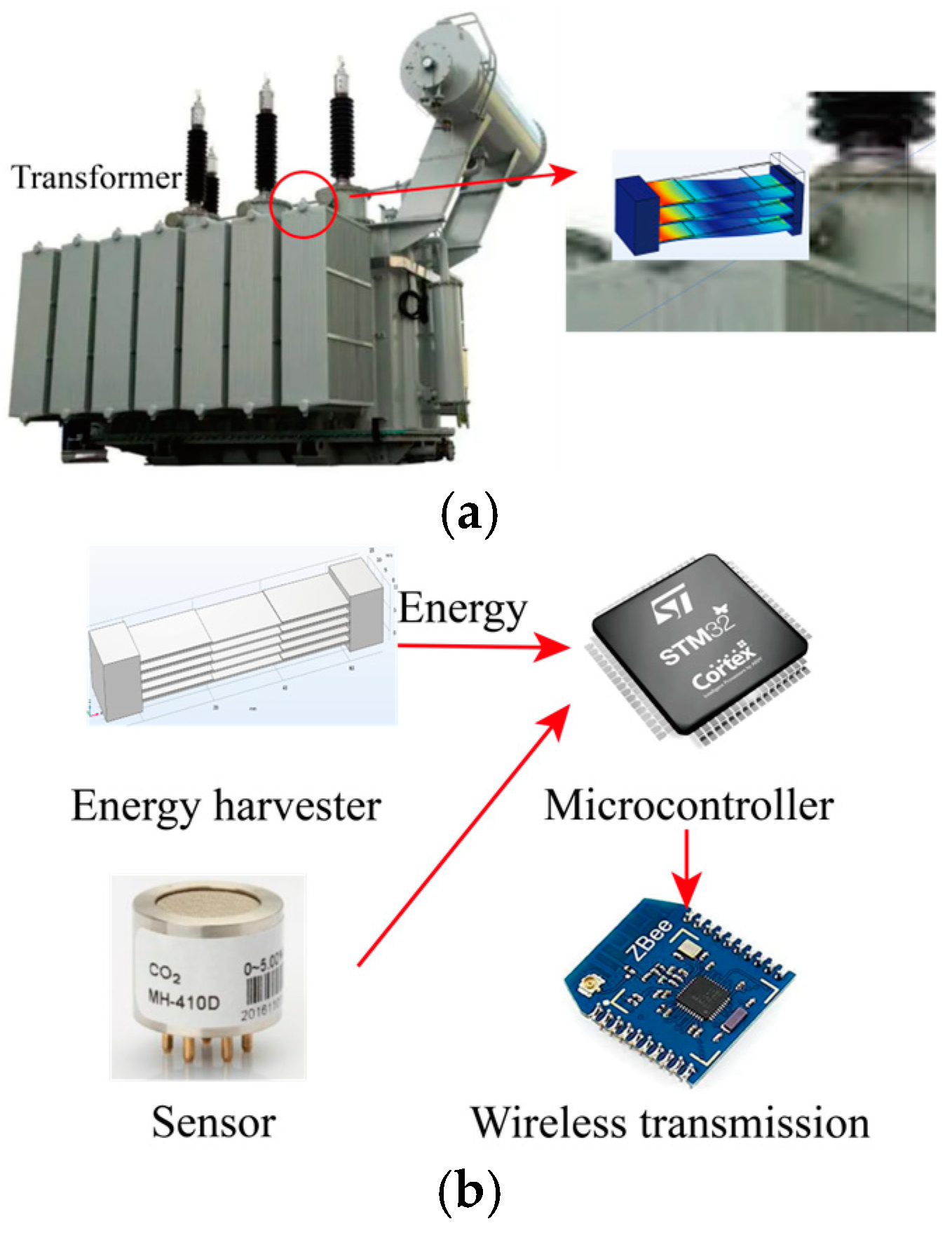
Figure 1. (a) PEH for transformer monitoring; (b) self-powered sensor node.
Applsci 14 10805 g001
Figure 2. (a) Prototype of the proposed multiple-cantilever PEH; (b) s-shape vibration mode.
Applsci 14 10805 g002
Figure 3. Experimental setup of the proposed PEH.
Applsci 14 10805 g003
Figure 4. (a) Diagram and (b) experimental platform of the wireless sensing node and host computer.
Applsci 14 10805 g004
Figure 5. (a) Forward and (b) backward open circuit voltage output of PZT1.
Applsci 14 10805 g005
Figure 6. Open circuit RMS voltage output of all the piezoelectric transducers.
Applsci 14 10805 g006
Figure 7. RMS power output performance of all the piezoelectric transducers.
Applsci 14 10805 g007
Figure 8. Control algorithm of the wireless sensor node.
Applsci 14 10805 g008
Figure 9. Operation of the wireless sensor node under 2.98 g excitation.
Applsci 14 10805 g009
Figure 10. Date acquisition on the host computer.
Applsci 14 10805 g010
Disclaimer/Publisher’s Note: The statements, opinions and data contained in all publications are solely those of the individual author(s) and contributor(s) and not of MDPI and/or the editor(s). MDPI and/or the editor(s) disclaim responsibility for any injury to people or property resulting from any ideas, methods, instructions or products referred to in the content.