Article

Adaptive Control Parameter Optimization of Permanent Magnet Synchronous Motors Based on Super-Helical Sliding Mode Control

by
Lingtao Kong
1,
Hongxin Zhang
1,*,
Tiezhu Zhang
1,
Junyi Wang
1,
Chaohui Yang
1,2 and
Zhen Zhang
1
1
College of Mechanical and Electrical Engineering, Qingdao University, Qingdao 266071, China
2
Qingte Group Limited, Qingdao 266041, China
*
Author to whom correspondence should be addressed.
Appl. Sci. 2024, 14(23), 10967; https://doi.org/10.3390/app142310967
Submission received: 11 August 2024 / Revised: 18 November 2024 / Accepted: 22 November 2024 / Published: 26 November 2024
(This article belongs to the Section Electrical, Electronics and Communications Engineering)

Abstract

:
Optimizing control rate parameters is one of the key technologies in motor control systems. To address the issues of weak robustness and slow response speed in traditional adaptive control strategies, an adaptive control system based on sliding mode control is proposed to enhance the overall performance of permanent magnet synchronous motors. The Non-dominated Sorting Genetic Algorithm II and Multi-objective Particle Swarm Optimization are employed to effectively optimize control parameters, thereby mitigating motor torque and speed overshoot. A Partial Sample Shannon Entropy Evaluation method, leveraging entropy theory in conjunction with the Z-score method, is introduced to facilitate the feedback regulation of the optimization process by assessing motor output torque. Simulation results confirm that the proposed control strategy, in combination with the optimized control rate parameters, leads to substantial improvements in motor performance. Compared to traditional adaptive control strategies, the proposed approach improves the motor’s steady-state response speed by 42% and reduces rotor error during system fluctuations by 23%, significantly enhancing the motor’s response speed and robustness. Following parameter optimization, speed and torque overshoot are reduced by 38% and 10%, respectively, resulting in a significant improvement in the stability and precision of the motor control system.

1. Introduction

1.1. Research Background

In recent years, issues such as climate change, energy crises, and other related concerns have gained increasing prominence globally, becoming an unavoidable reality. Consequently, governments worldwide have placed significant emphasis on environmental protection, energy conservation, emission reductions, and sustainable development. This heightened attention has led to a surge in investments in the field of new energy [1,2,3]. Permanent magnet synchronous motors (PMSM) find extensive use in electric vehicles, rail transportation, ship propulsion, and various other domains due to their remarkable attributes, including high efficiency, elevated power density, robust overload capacity, and superior performance [4,5]. Notably, PMSMs exhibit more stable performances compared to DC motors [6]. Moreover, when contrasted with asynchronous motors, PMSMs are distinguished by their high power factor, rendering them the preferred choice for energy conservation in motor systems [7].

1.2. Literature Review

More sophisticated control methods are necessary to enhance the performance of PMSMs [3]. Currently, prominent PMSM control methods include constant voltage-to-frequency ratio control, magnetic field orientation control, and direct torque control [8]. Position sensorless control technology for PMSMs simplifies the control system by employing suitable control algorithms to estimate rotor speed and position [9]. Key position sensorless control techniques encompass the Sliding Mode Observer method, the Model Reference Adaptive System method, and the Extended Kalman Filter method. The model-referenced adaptive speed control was proposed, utilizing an ultra-twisted sliding mode observer to estimate and compensate for aggregate perturbations [10]. This approach updates the error compensation term online using adaptive rates, leading to improved dynamic performance and robustness in speed tracking control for PMSMs, as demonstrated through both experiments and simulations. Additionally, Zhang proposed a bi-level fuzzy exponential convergence rate fractional order sliding mode control, which enhances the control performance and robustness of motor drives, as evidenced by simulation results [11]. Wang designed a super-helical sliding mode observer that mitigates the chattering issue typically associated with sliding mode observers while enhancing system robustness. This approach effectively addresses the jitter problem of traditional sensor systems [12]. Zhao introduced a sliding mode control method for fast terminal sliding mode observers in permanent magnet synchronous motor drive systems, effectively reducing system dependence on accurate models and improving disturbance immunity [13]. A robust current control method with disturbance cross-coupling compensation was proposed by Gabbi, employing a discrete-time backstepping perturbation observer combined with a sliding mode controller to improve system robustness and stability, as indicated by simulation results [14]. Huang suggested a control strategy that combines a robust two-degree-of-freedom controller and an extended sliding mode parameter observer. This strategy utilizes iterative learning control and a series structure to suppress unmodeled perturbations and periodic components, with the ESMPO enhancing parameter identification to improve anti-interference capabilities [15]. Shweta proposed the Model Predictive Control method for driving the current loop, employing Higher Order Sliding Mode Control for the outer speed loop and a Super twisting Algorithm to suppress jitter, thereby effectively enhancing motor performance [16]. Xu proposed a comprehensive electromagnetic model to address elliptical and corrugated deviations. In their research, a three-pole active magnetic bearing with a simple structure was employed to dampen vibrations and was integrated into a permanent magnet synchronous motor system. By utilizing the iterative sliding mode control in the design of the control system, the motor’s vibration is effectively mitigated [17]. To mitigate pulsations, Zhang devised a robust insertion repetition controller with phase compensation within the outer speed loop of the cascade PI control system in a permanent magnet synchronous motor. Additionally, a third-order Butterworth filter with phase correction is proposed to enhance the system’s resilience against low-frequency periodic disturbances and ensure its high-frequency stability [18]. Applying a barrier function-based adaptive strategy to first-order disturbed systems significantly enhances system robustness while maintaining effective performance [19]. Cruz-Ancona proposed a uniform reaching phase strategy within adaptive sliding mode control, effectively ensuring uniform reaching of the sliding phase within a predetermined time while adapting to the perturbation norm [20]. In the presence of uncertainties and disturbances, the application of adaptive barrier function-based gain for unit control has effectively achieved an arbitrary a priori predefined uniform ultimate bound for solutions [21]. González proposes a bi-powered extension of the methodology, which can effectively adjust the size of the final set for any value of the upper bound of the perturbation [22]. Plestan proposed a novel adaptive sliding mode control design that effectively obtained a robust sliding mode adaptive-gain control law under the assumption of boundness system characteristics [23]. Utkin utilized a low-pass filter to evaluate the so-called equivalent control, effectively reducing the high-frequency oscillations associated with sliding mode control. This approach helps mitigate the chattering phenomenon, which is common in sliding mode control systems, enhancing both stability and performance in practical implementations [24]. In disturbed linear systems, the use of robust nonlinear model reference adaptive control strategies effectively improves the algorithm’s execution speed. This control approach enhances system response times by quickly adapting to disturbances and uncertainties, offering robust performance under dynamic conditions [25]. Adaptive high-order sliding mode control has become a hot topic in recent years, as it effectively addresses unknown bounds while mitigating chattering. This control strategy enhances system performance by improving robustness and stability under uncertainties, making it suitable for various applications [26].
The speed and torque overshoot of PMSMs are critical factors in evaluating control strategies for these motors. Optimizing control strategies using appropriate optimization algorithms is particularly significant in this regard [27,28]. MOPSO and NSGA II are popular multi-objective optimization algorithms that have successfully addressed various multi-objective optimization problems across numerous fields. Their effectiveness in providing optimal solutions has made them widely adopted in applications such as engineering design, logistics, and resource management [29,30]. Yuan proposed a three-stage, seven-step optimization method assisted by neural networks. This method employs neural network techniques to provide dedicated correction factors for analyzing PMSM quality and loss estimates across the design space, resulting in faster and more accurate auxiliary analysis models [31]. Srivastava applied Khalil’s H∞ Observer-Kalman Filter Optimization algorithm for parameter estimation in PMSMs, with simulation experiments demonstrating its superior convergence rate and error performance evaluation [32]. Yousri introduced the Chaotic Whale Optimization Variant optimization technique, with overall results indicating that the CwoA-Il variant, utilizing logistic chaotic mapping, exhibits the best performance among all variants. It shows smaller error values between estimation and original system performance, faster convergence, and shorter execution time, ensuring rapid motor control and protection against damage [33]. Sun presented a multi-objective optimization design for PMSMs based on the Multi-Objective Comprehensive Teaching and Learning Algorithm. This approach addresses the complexity of PMSM optimization problems and the presence of numerous variables. The algorithm, an improvement over teaching and learning-based optimization algorithms, demonstrates better adaptation to large-scale sample spaces and multivariate optimization [34]. Wang proposed a new voltage optimization algorithm to enhance the operating performance of PMSMs. This algorithm, based on the particle swarm algorithm, combines online and secondary optimization improvements. The results show a 16.22% reduction in current ripple and a 65.14% decrease in steady-state speed fluctuation compared to a similar speed response achieved with Dual Vector Modulated Predictive Current Control [35]. Liu combined an improved artificial potential field algorithm with an obstacle boundary model, effectively achieving smooth obstacle-avoidance path planning from the starting point to the destination [36].

1.3. Contributions of the Work

(a)
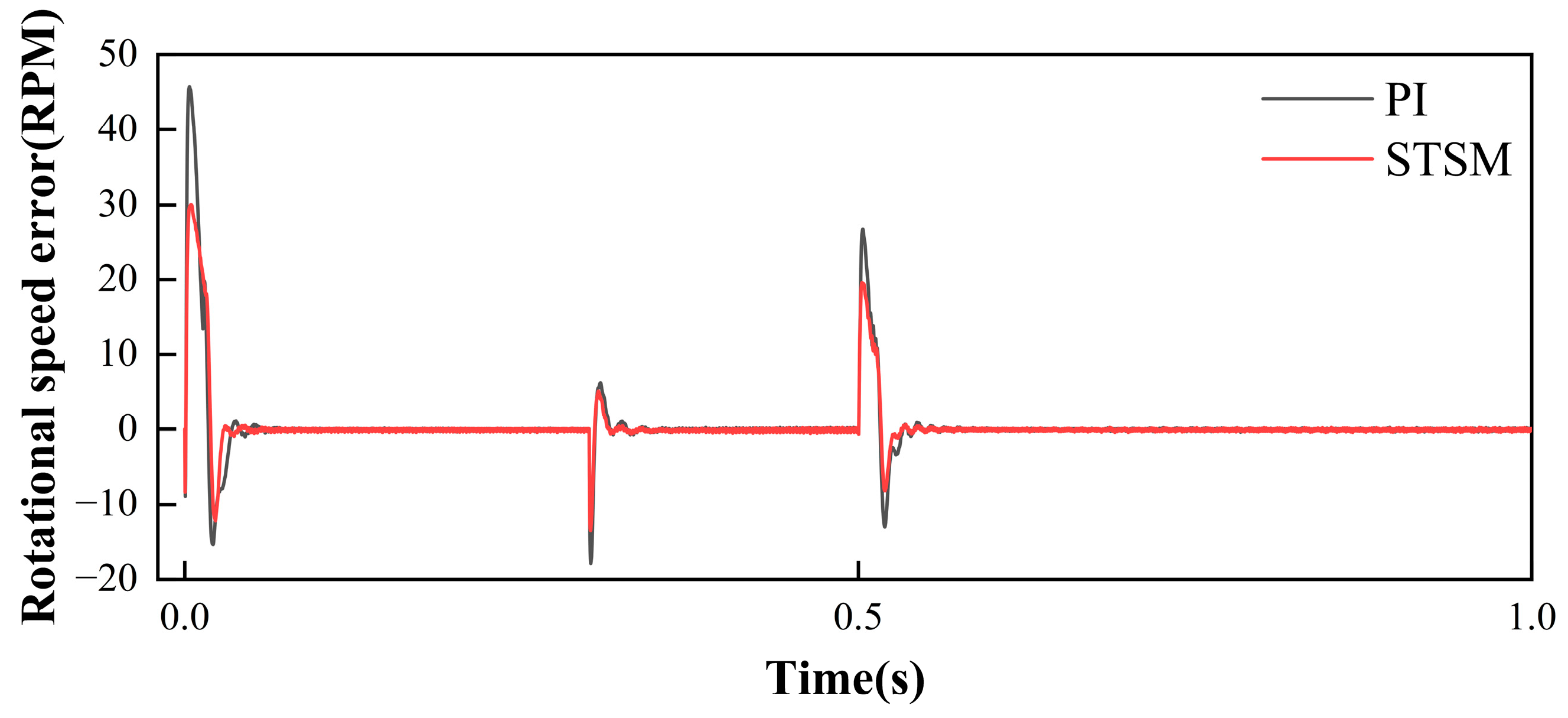
Adaptive control method for permanent magnet synchronous motors based on super-helical sliding mode control: A novel adaptive control system for permanent magnet synchronous motors, employing super-helical sliding mode control, is proposed. This system exhibits superior performance in terms of response speed, robustness, and steady-state behavior when compared to conventional control systems.
(b)
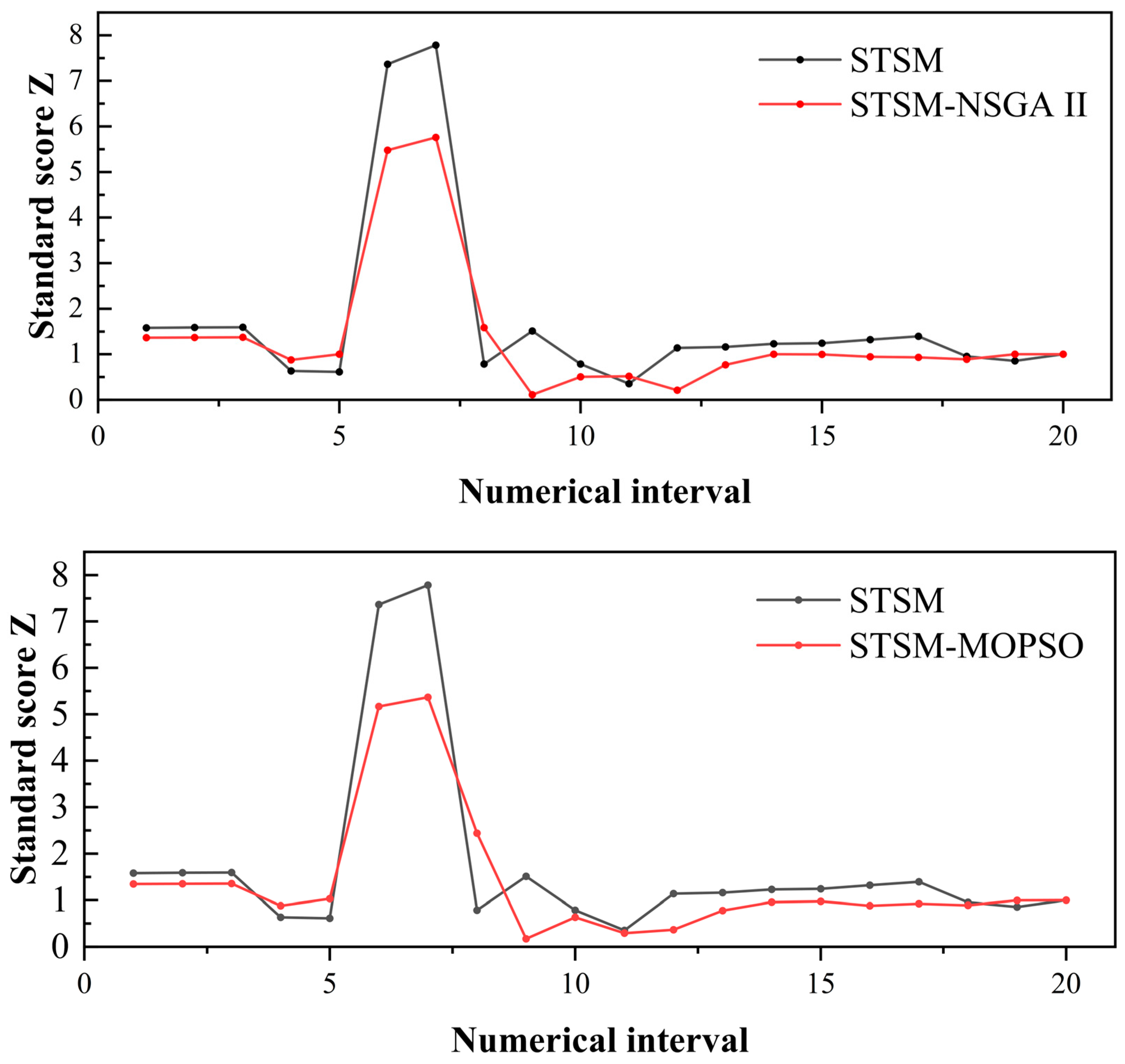
Optimization of adaptive control parameters for permanent magnet synchronous motors: Two optimization algorithms, NSGA II and MOPSO, are utilized to optimize the parameters of the established system. Simulation results indicate a notable decrease in rotational speed and torque overshooting of permanent magnet synchronous motors under both optimization algorithms, highlighting significant optimization outcomes.
(c)
Partial Sample Shannon Entropy Evaluation: To facilitate a comprehensive comparison of torque performance improvement under different optimization algorithms, this paper introduces the Shannon entropy-based torque evaluation strategy, PSSEE. This strategy effectively evaluates the motor’s output torque, revealing torque data accumulation through conversion into a standard fractional Z-curve. The optimization algorithm with the best performance is screened on the basis of torque analysis, which effectively improves the robustness of the motor.

1.4. Organization of the Paper

The subsequent sections of this paper are structured as follows: The second section delineates the mathematical model of the permanent magnet synchronous motor. The principle of the adaptive control strategy model based on the super-helical sliding mode is elaborated in the third section. In the fourth section, the optimization design is elucidated, along with the process of establishing the partial sample Shannon entropy assessment method. The fifth section conducts an analysis of the feasibility and efficacy of the proposed control rate optimization algorithm, affirming its considerable research value and prospective applications. Finally, the sixth section provides the conclusion and outlines future research directions.

2. Mathematical Model of Permanent Magnet Synchronous Motor

The voltage equation for a permanent magnet synchronous motor in the d-q coordinate system is expressed as follows:
V d = R s I d + L d d d t I d ω e L q I q V q = R s I q + L q d d t I q + ω e L d I d + ψ f
Here, Vd and Vq represent the d-q axis components of the stator voltage, Id and Iq denote the d-axis and q-axis current components, Ld and Lq represent the d-axis and q-axis inductance components, respectively, while ψf represents the permanent magnet flux linkage. For surface-mounted motors, Ld = Lq. ωe represents the angular velocity (rotational speed) of the motor.
Based on Equation (1), we can derive the equivalent voltage circuit in the synchronously rotating d-q reference frame, as depicted in Figure 1.
The electromagnetic torque equation for a permanent magnet synchronous motor in the d-q coordinate system is given below [37]:
T e = 3 2 p ψ f I q + L d L q I d I q
This equation describes the electromagnetic torque Te produced by the motor, where P represents the number of pole pairs.

3. Principles and Modeling of an Adaptive Control Method for PMSMs Based on Super-Helical SMC

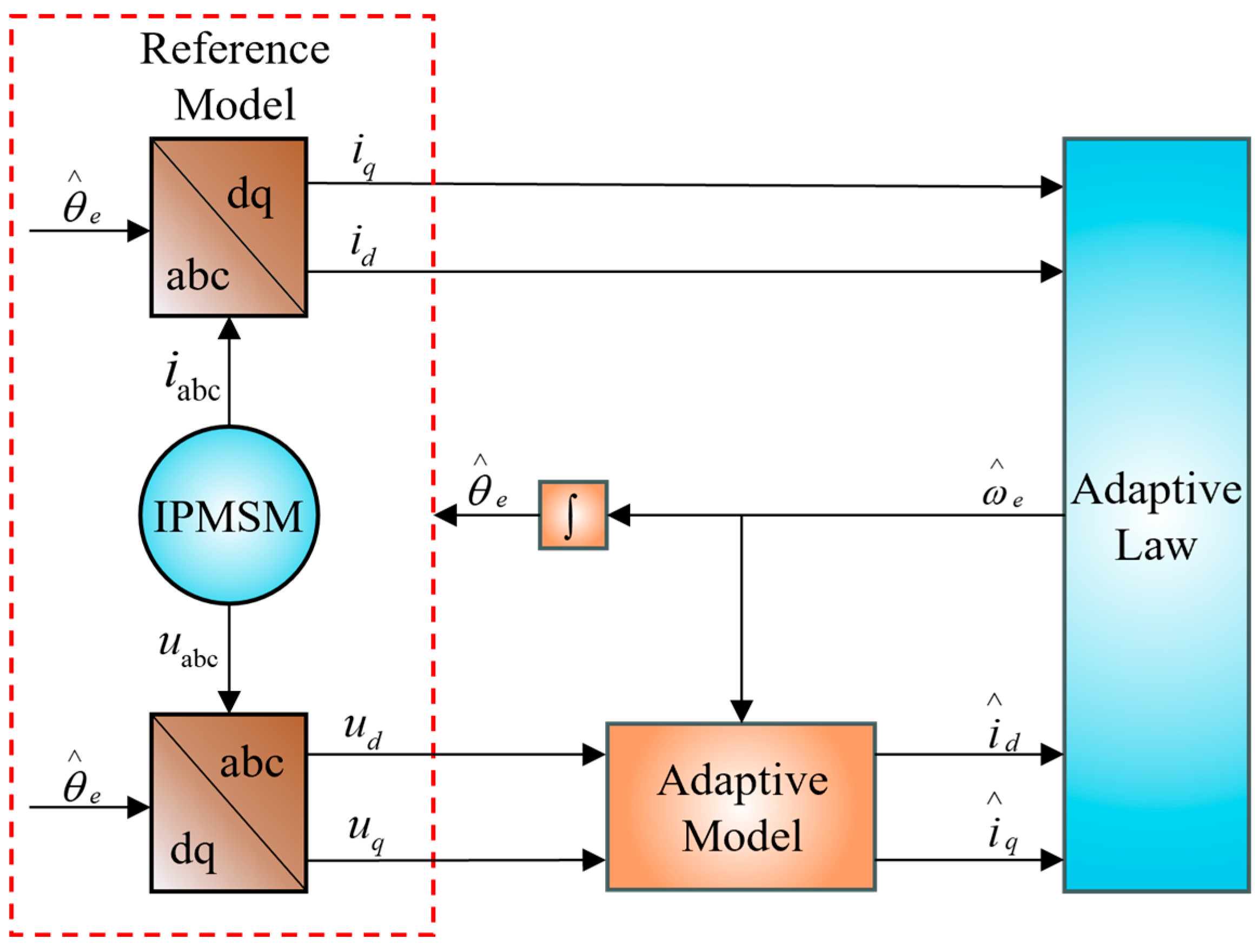
3.1. MRAS-Based PMSM Position Sensorless Control System

The principle behind Model Reference Adaptive Systems (MRAS) involves treating the parameters to be identified as adjustable parameters. Here, the expression containing these parameters serves as the adjustable model, while the expression devoid of unknown parameters acts as the reference model. Ensuring the physical significance of x and x ^ , the difference between them forms the generalized error e . Designing a suitable adaptive law facilitates the adjustment of the parameters in the adjustable model, thereby minimizing e and ensuring the asymptotic stability of the system output. Ultimately, this process enables accurate identification of the system parameters.
For the embedded PMSM, the voltage equation in the synchronous rotating coordinate system is represented by Equations (1) and (2). To facilitate analysis and design, it is rewritten as follows:
d d t I d = R s L d I d + ω e L q L d I q + 1 L d V d d d t I q = R s L q I q ω e L d L q I d ψ f L q ω e + 1 L q V q
To obtain an adjustable model, Equation (3) can be changed to the following:
d d t i = A i + B u
where i = I d I q , u = V d V q , A = R s L d ω L q L d ω L d L q R s L q and B = 1 L d 0 0 1 L q .
Expressing Equation (4) in terms of estimates can be abbreviated as follows:
d d t i ^ = A ^ i ^ + B u
Included among these, i ^ = i ^ i ^ q , A ^ = R L d ω ^ e L q L d ω ^ e L d L q R L q .
Since the matrices A and A ^ both have rotor information, it is possible to use Equation (5) as the adjustable model, Equation (3) as the reference model, and ω as the adjustable parameter. The generalized error is defined as e = i i ^ , which is obtained by subtracting Equations (4) and (5), shown in the following:
d d t e d e q = R s L d ω L q L d ω L d L q R s L q e d e q J ( ω ^ ω ) i ^ d i ^ q
It can be simplified as follows:
e ˙ = A e W V = C e
Figure 2 illustrates the standard feedback system derived from Equation (7). In the upper half of the dashed box, the forward channel represents a linear time-invariant system, with C denoting a linear compensator. Meanwhile, the lower half of the dashed box represents a nonlinear time-varying feedback channel.
In this research project, the Popov super stability theory is employed to demonstrate that the transfer function matrix G(s) of the linear time-invariant forward channel becomes a strictly positive real matrix when the linear compensator conforms to Equation (8). Additionally, it is established that the nonlinear time-invariant feedback channel satisfies the Popov integral inequality under the rotational speed estimation formula given by Equation (9).
C = L d L q 0 0 L q L d
ω ^ = ( K i s + K p ) I d I q I d i q ψ f L d ( i q i ^ q ) + ω ^ ( 0 )
The model-referenced adaptive rotor position and speed estimation system based on stator currents are shown in Figure 3.
The reference model initially receives the estimated electrical angle obtained from the adaptive rate and generates the three-phase current (iabc) and voltage (uabc) parameters using reference model equations. These parameters are then transformed from the natural coordinate system to the rotating coordinate system through coordinate transformation. Concurrently, the adjustable model receives the estimated rotational speed via the adaptive law. Utilizing Equation (6), the adjustable model computes the voltage values (ud and uq) passed by the reference model, producing an estimated alternating shaft current. Subsequently, this current is fed into the adaptive law. The adaptive law, in turn, receives both the actual alternating shaft currents (id and iq) from the reference model, as well as the estimated alternating shaft currents (id and iq) from the adaptive law’s rotational speed estimation, as defined by Equation (9). By integrating these inputs, the adaptive law computes the estimated rotational speed ω. This estimated speed is further processed by the adaptive law speed estimation Equation (9) to produce the estimated rotor position angle θ. This angle, representing the estimated rotor speed ω, is then fed back to the reference model, thereby enabling closed-loop control of the motor system without the need for a position sensor.

System Stability Proof

As per the Popov hyperstability theory, to ensure the asymptotic stability of the system, the following two conditions must be satisfied:
(1) As per the Positive Real Lemma, the transfer function matrix G ( s ) = C ( s I A ) 1 of the linear time-invariant forward path is a strictly positive real matrix. For the following state-space representation of the linear time-invariant system, the conditions of the lemma apply:
x ˙ ( t ) = A x ( t ) + B u ( t ) y ( t ) = C x ( t ) + D u ( t )
The necessary and sufficient condition for its transfer function matrix G ( s ) = D + C ( s I A ) 1 B to be a strictly positive real matrix is the existence of a symmetric positive definite matrix P and real matrices K and L, with positive real numbers, or a symmetric positive definite matrix Q satisfying:
P A + A T P = L L T 2 λ P = Q B T P + K T L T = C K T K = D + D T
For Equation (7), since B = I and D = 0, Equation (11) can be simplified to:
P A + A T P = Q P = C
Choose:
C = L d L q 0 0 L q L d
Then, according to Equation (12), P = C is also a symmetric positive definite matrix. By substituting matrix A and the new matrix P into Equation (12), we obtain:
Q = ( P A + A T P ) = 2 R L q 0 0 2 R L d
It is evident that Q is a symmetric positive definite matrix. Therefore, for permanent magnet synchronous motor, when the linear compensator matrix C is chosen as given in Equation (4), the transfer function matrix G(s) of the linear time-invariant forward channel is a strictly positive real matrix.
(2) The nonlinear time-varying feedback channel satisfies the Popov integral inequality:
η ( 0 , t 1 ) = 0 t 1 V T W d t γ 0 2 ( t 1 0 )
The design of the adaptive law in the nonlinear time-varying feedback channel must ensure that the nonlinear feedback channel satisfies Inequality (14). By substituting V = Ce and W into Equation (14), we obtain:
η ( 0 , t 1 ) = 0 t 1 e T C J ( ω ^ e ω e ) i ^ d t γ 0 2 , t 1 0
In the proportional-integral form of the model reference adaptive system, ω ^ e can be expressed as:
ω ^ e = 0 t F 1 ( v , t , τ ) d τ + F 2 ( v , t ) + ω ^ e ( 0 )
In the equation, ω ^ e ( 0 ) represents the estimated initial value of the speed.
Substituting Equation (16) into Equation (15) yields:
η ( 0 , t 1 ) = 0 t 1 0 t F 1 ( v , t , τ ) d τ + F 2 ( v , t ) + ω ^ e ( 0 ) ω e e T C J i ^ d t = η 1 ( 0 , t 1 ) + η 2 ( 0 , t 1 )
To ensure that η ( 0 , t 1 ) γ 0 2 , it is necessary to satisfy the following conditions individually:
η 1 ( 0 , t 1 ) = 0 t 1 0 t F 1 ( v , t , τ ) d τ + ω ^ e ( 0 ) ω e e T C J i ^ d t γ 1 2
η 2 ( 0 , t 1 ) = 0 t 1 F 2 ( v , t ) e T C J i ^ d t γ 2 2
In the equation, γ 1 2 and γ 2 2 are both finite positive numbers.
To construct a function f(t) that satisfies Inequality (18), we can define f(t) as follows:
K i f ( t ) = 0 t F 1 ( v , t , τ ) d τ + ω ^ e ( 0 ) ω e d f ( t ) d t = e T C J i ^
In the equation, Ki > 0.
Substituting Equation (20) into Equation (18) yields the following:
η 1 ( 0 , t 1 ) = 0 t 1 d f ( t ) d t K i f ( t ) d t = K i 2 f 2 ( t ) f 2 ( 0 ) 1 2 K i f 2 ( 0 ) γ 1 2
By differentiating the first equation in Equation (20) and using the second equality in Equation (20), we obtain the following:
F 1 ( v , t , τ ) = K i e T C J i ^ ( K i > 0 )
If the integrand in Equation (19) is positive, then the inequality is guaranteed to hold. Thus, we choose the following equation:
F 2 ( v , t ) = K p e T C J i ^ ( K p > 0 )
Substituting the above expression into Equation (19) yields the following:
η 2 ( 0 , t 1 ) = 0 t 1 K p ( e T C J i ^ ) 2 d t 0 γ 2 2
Thus, the proof is complete. Substituting F 1 ( v , t , τ ) and F 2 ( v , t ) into Equation (16), the speed estimation formula can be obtained as follows:
ω ^ e = 0 t K i e T C J i ^ d τ + K p e T C J i ^ + ω ^ e ( 0 )

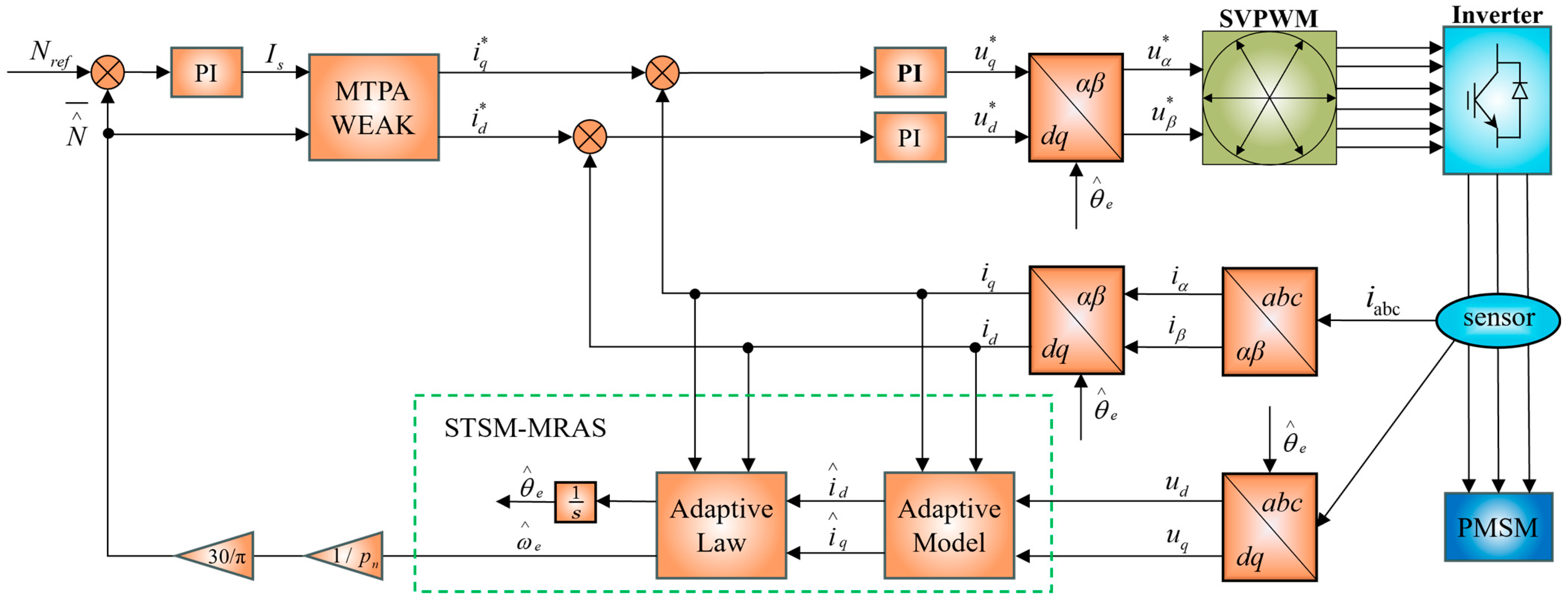
3.2. Model-Referenced Adaptive Control System Based on Super-Helical Sliding Mode Control

This research proposes a super-helical sliding mode control to replace the PI adaptive control parameters in Model Reference Adaptive Systems (MRASs), as discussed in the previous section. This approach aims to address the issue of weak robustness associated with traditional MRASs. The basic form of this super-helical sliding mode control is presented below:
x ˙ 1 = k 1 x 1 1 / 2 sgn ( x 1 ) + x 2 x ˙ 2 = k 2 sgn ( x 1 )
The sign function, sgn(), is a discontinuous function, and its presence leads to chattering issues in sliding mode control. However, as shown in Equation (26), super-twisting sliding mode control (STSMC) essentially acts as a second-order sliding mode controller. By introducing continuous terms before the sgn() function and placing sgn() in the higher-order derivative, the traditional chattering problem in sliding mode control is alleviated to a certain extent. Moreover, STSMC also exhibits robust performance under various disturbances and uncertainties.
Combined with Equation (26), the formulated slip film surface is as follows:
s = i d i ^ q i ^ d i q ψ f L d ( i q i ^ q )
The derivation of Equation (27) involves the application of the basic principle of sliding mode variable structure. Specifically, when the system enters the sliding mode surface, s = s = 0 , the equivalent velocity expression is as follows:
ω e q = ω e + ( R L d + R L q ) ( i ^ d i q i d i ^ q ) + u q L q ( i d i ^ d ) + ( R ψ f L d L q u d L d ) ( i q i ^ q ) L d L q i d i ^ d + L q L d i q i ^ q + ψ f L q ( i d + i ^ d ) + ψ f 2 L d L q
Based on the equivalent velocity and sliding mode surface, the velocity observer is designed in conjunction with the super-helical sliding mode control. Equation (29) presents the velocity prediction expression and the rotor position estimate is obtained by integrating Equation (29).
ω ^ e = k 1 s 1 / 2 sgn ( s ) + t 0 k 2 sgn ( s ) d t + ω ^ e ( 0 )

System Stability Proof

According to the Lyapunov stability theorem, the state vector is selected as follows:
Z = Z 1 Z 2 T = x 1 1 2 sgn ( x 1 ) x 2 T
In this case, Z1 and Z2 are selected as the state variables. From Equation (30), it is evident that if the state variables Z1 and Z2 can be shown to converge to zero in finite time, then x1 and x2 will also converge to zero in finite time. Combined with Equation (26), this confirms that the system states will reach the sliding mode surface and converge to zero in finite time.
Taking the time derivative of the state vector Z, combined with Equation (26), yields the following:
Z ˙ = 1 2 x 1 1 2 x ˙ 1 x ˙ 2 = 1 2 x 1 1 2 k 1 x 1 1 2 sgn ( x 1 ) + x 2 k 2 sgn ( x 1 ) = 1 x 1 1 2 k 1 2 1 2 k 2 0 x 1 1 2 sgn ( x 1 ) x 2 = 1 x 1 1 2 F Z
In this context, F = k 1 2 1 2 k 2 0 .
We construct the following Lyapunov function, where N = 1 2 k 1 2 + 4 k 2 k 1 k 1 2 .
V ( Z ) = Z T N Z
The time derivative of V(Z) is given by the equation below:
V ˙ ( Z ) = Z ˙ T N Z + Z T N Z ˙
Substituting Equation (31) into Equation (33) yields the following:
V ˙ ( Z ) = 1 x 1 1 2 Z T F T N Z + 1 x 1 1 2 Z T N F Z = 1 x 1 1 2 Z T ( F T N + N F ) Z = 1 x 1 1 2 Z T M Z
In this context, M = ( F T N + N F ) .
Substituting F = k 1 2 1 2 k 2 0 and N = 1 2 k 1 2 + 4 k 2 k 1 k 1 2 into the expression for matrix M results in the following:
M = k 1 2 k 1 2 + 2 k 2 k 1 k 1 1
To prove that matrices M and N are positive definite using Sylvester’s criterion, it is necessary to verify that all principal minors of the matrices are positive. For a 2 × 2 matrix, Sylvester’s criterion stipulates the following conditions: the first principal minor (i.e., the top-left element of the matrix) must be positive, and the determinant of the matrix must also be positive. For the matrix M, M11 and det(M) are given by Equation (36).
M 11 = k 1 2 k 1 2 + 2 k 2 det ( M ) = k 1 2 k 1 2 + 2 k 2 1 k 1 2 = k 1 k 2
Since k1 > 0 and k2 > 0, it can be concluded that M is a positive definite matrix. For the matrix N, N11 and det(N) are given by Equation (37).
N 11 = k 1 2 2 + 2 k 2 det ( N ) = 1 2 k 1 2 + 4 k 2 2 k 1 2 = k 1 2 2 + 4 k 2
From k1 > 0 and k2 > 0, it can be concluded that N is a positive definite matrix. Consequently, it follows that V ˙ ( Z ) < 0, indicating that V ˙ ( Z ) is a negative definite matrix.
When the sliding mode gains k1 and k2 in the expression of the super-spiral sliding mode control (Equation (26)) are greater than zero, both matrices N and M are symmetric positive definite. Under these conditions, the matrix V ˙ ( Z ) is negative definite, which implies that the system is asymptotically stable at the equilibrium point (the origin).

3.3. MRAS Control System Based on Super-Helical Sliding Mode

The super-helical sliding mode control replaces the PI adaptive control parameters in the MRAS control, which relies on stator current. The corresponding control system block diagram is depicted in Figure 4 and the variables marked with * denote reference or target values essential for motor control, predominantly determined by control algorithms or regulators.
The permanent magnet synchronous motor receives the estimated electrical angle transmitted from the adaptive rate. Subsequently, the electrical angle is used by the adaptive controller to generate the parameters for three-phase current and three-phase voltage. These parameters are then transformed into DC voltage and current parameters on the dq-axis through a coordinate system transformation. Meanwhile, the adjustable mode calculates the estimated current of the dq-axis using Equation (5) and forwards this signal to the adaptive rate. The adaptive rate operates based on the sliding mode (Equation (11)). The output of the adaptive rate is then passed to the speed observer, which estimates the rotor speed according to Equation (13). Finally, the estimated rotor speed is integrated to produce the estimated rotor position angle. This enables the closed-loop control of the permanent magnet synchronous motor without the need for a position sensor.

4. Optimization of Adaptive Control Parameters for Permanent Magnet Synchronous Motors

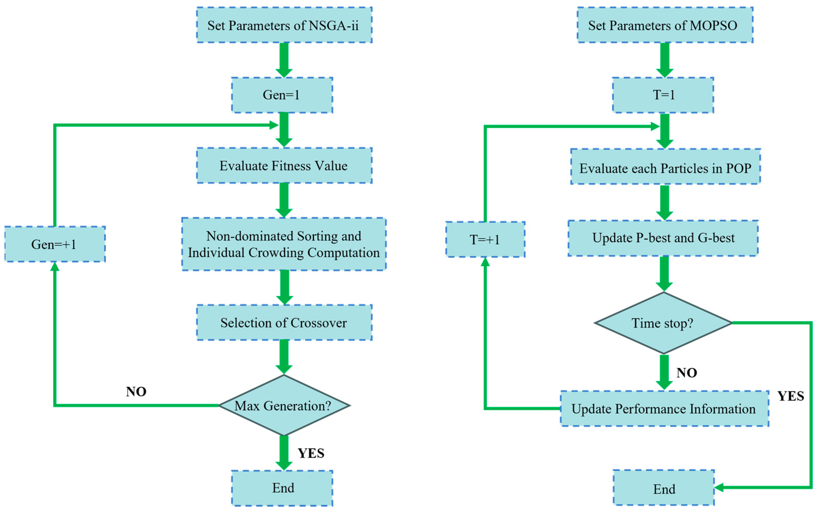
4.1. Parameter Optimization System

The improvement of motor performance requires continuous technical innovation and optimization of control parameters. In this paper, the adaptive control strategy of the permanent magnet synchronous motor is the main research object, and optimization research is carried out to improve the performance of the permanent magnet synchronous motor. In this paper, the Multi-objective Particle Swarm Optimization Algorithm and the Non-dominated Sorting Genetic Algorithm II are mainly used to enhance the robustness and stability of the permanent magnet synchronous motor. By integrating the Isight software (v.4.5) with Simulink (2023b), the optimization results of the desired objectives can be obtained easily and effectively. The main focus of this section is the establishment of the optimization system.
The Isight software is a professional engineering analysis software for parameter optimization, design exploration, and model calibration. With Isight, we can define design variables, objective functions, and constraints to automate the search for optimal designs, thus saving time and resources. Its main advantage is the automated optimization process, which allows efficient optimization without manually adjusting parameters, as well as the global search capability, which allows us to search for the optimal solution in a large parameter space. At the same time, the Isight software supports a variety of optimization algorithms, such as genetic algorithms, particle swarm optimization, etc., which can be used to select the appropriate algorithm for optimization according to the specific problem. Building on its previously highlighted strengths, the Isight software also offers parallel computation, flexibility, and scalability in parameter optimization, enabling fast and effective design optimization and improving the performance and quality of the product. In this paper, the Isight software is integrated with Simulink to achieve the desired optimization objectives.
There are many factors affecting the performance of the motor, and in the adaptive control strategy proposed in Section 3 of this paper, we conclude through theoretical analysis that the sliding mode control parameters and the PID control parameters in the weak magnetic control of the MTPA have the most significant influence on the performance of the motor. In order to improve the stability and robustness of the motor, we determined that the sliding mode control parameters (K1 and K2) in the STSM-MRAS and the PID control parameters (Kp and Ki), in the weak magnetic control of MTPA are the four design variables in this paper.
Response output refers to the final output parameter of the optimization system, and it is also the index for evaluating the optimization process and results. In this paper, we select the response output as the peak speed and peak torque of the motor, and the optimization objective is to obtain the minimum response output at reasonable control parameters.
In electric motor control systems, the reduction in torque overshoot significantly enhances system stability and facilitates smoother operational responses, thereby leading to improvements in overall performance and longevity. This aspect is especially crucial in new energy vehicles, wherein the torque generated by the motor directly influences the overall driving experience. Excessive torque overshoot may result in abrupt acceleration or deceleration, which adversely impacts driving comfort and safety. By minimizing torque overshoot, a more seamless and linear acceleration experience can be attained. Furthermore, the reduction in torque overshoot mitigates mechanical shocks, thereby prolonging the lifespan of critical components and reducing maintenance costs. Moreover, it aids in preventing unnecessary energy waste, particularly during frequent starts, stops, and speed transitions, which is essential for enhancing vehicle range.
The reduction in motor speed overshoot presents substantial advantages in terms of technical performance. In the context of robotic arm motors, the minimization of speed overshoot allows the robot to achieve designated positions with enhanced accuracy, consequently diminishing deviations resulting from overshoot. Such precision is especially critical during tasks that involve intricate assemblies or complex operations. Furthermore, a smoother speed response facilitates the robot’s more sensitive reaction to variations in the external environment, thereby enhancing its responsiveness to commands, particularly during rapid movements and complex tasks.
In this paper, the chosen form of constraint is based on the original control parameters, adjusted up and down by twenty percent to adjust the control according to the rules of the permanent magnet synchronous motor control. Using the original parameter settings, we set the parameter ranges as follows: Ki ranges from 0.04–0.06, Kp ranges from 4–6, K1 ranges from 40–60, and K2 ranges from 8–12.
The peak rotational speed and peak torque of an electric motor are two key indicators reflecting the motor’s performance. Their expressions are shown as follows:
T e = max 3 2 P ψ f I q + L d L q I d I q
ω n = max V q R s I q ψ f L q I q
where P is the number of pole pairs of the motor, ψ f represents the magnetic flux, Id and Iq denote the d-axis and q-axis current components, Ld and Lq represent the d-axis and q-axis inductance components, Vq is the q-axis voltage, and Rs is the stator resistance.
The value function for the peak torque is as follows:
T e max = min T e i i = 1 , 2 I t e r
Here, i is the iteration count, Iter represents the maximum number of iterations, and Tei denotes the peak torque obtained at each iteration.
The value function for the peak rotational speed is as follows:
ω n max = min ω n i , i = 1 , 2 l t e r
Here, ωnmax represents the peak rotational speed obtained at each iteration.
The total cost function is shown below:
C = α T e max + β ω n max
where α and β are weighting factors.
This study employs the Non-dominated Sorting Genetic Algorithm II (NSGA-II) and the Multi-objective Particle Swarm Optimization (MOPSO) to optimize the control parameters of the permanent magnet synchronous motor (PMSM) in line with its specific control requirements. Adaptive control parameters are independently derived from both algorithms, and their performance is evaluated to determine the most effective control parameters.
NSGA-II is an improved version of the non-dominated genetic algorithm, which aims to find a set of solutions that can optimize multiple objective functions at the same time. The principle of NSGA-II is shown in Figure 5. Compared with traditional optimization algorithms, NSGA-II introduces the concepts of non-dominated ordering and congestion distance, which maintains a more homogeneous distribution of Pareto fronts. Therefore, we chose NSGA-II as the first optimization algorithm to minimize peak torque Te and peak speed ωn of the PMSM.
The initial parameters of NSGA-II are defined as fixed values within the optimization algorithm, with their settings being judiciously adjusted to align with the complexity of specific problems. In this study, once the algorithm’s initial parameters are established, they remain constant throughout the optimization process. This consistency guarantees stable performance during the search for the requisite particles, ultimately yielding optimal solutions for the adaptive control rate parameters (K1, K2, Kp, and Ki). The specific initial parameter settings are thoroughly delineated in Table 1.
The Multi-objective Particle Swarm Optimization (MOPSO) algorithm is a multi-objective optimization algorithm that is an extension of the Particle Swarm Optimization algorithm and is specifically designed for solving multi-objective optimization problems. MOPSO aims to find the set of non-dominated solutions to a problem, i.e., a set of solutions in which none is dominated by any other solution across all objective functions. MOPSO uses a non-dominated sorting method to efficiently partition the solution into different levels on the Pareto frontier. This helps to provide multiple feasible solutions to the problem, forming a balanced set of Pareto-optimal solutions. MOPSO introduces the concept of congestion distance into the algorithm by adjusting the positions of the particles in order to maintain the diversity of solutions. This helps to maintain an even distribution of solutions on the Pareto front, thus providing a more comprehensive solution set. MOPSO can also improve search efficiency near the local Pareto front by introducing a local search mechanism. Due to the advantages of MOPSO in multi-objective optimization, it is used as the second optimization algorithm in this paper, and its principle is shown in Figure 5.
The initial parameter settings for MOPSO are analogous to those employed in comparable optimization algorithms. Appropriately chosen fixed parameter settings within the algorithm ensure consistent operational behavior, thus averting instability in results induced by parameter fluctuations, ultimately resulting in optimal solutions for the adaptive control rate parameters (K1, K2, Kp, and Ki) through the optimization process. To attain favorable optimization outcomes, the initial parameter settings employed in this study are delineated in Table 2.
Figure 6 depicts the evolution of the optimized control rates in this study. As observed, the motor control parameters K1, K2, Kp, and Ki exhibit gradual convergence under both optimization algorithms. Specifically, the NSGA-II algorithm yields optimal parameters of 48.53, 10.38, 0.041, and 4.07, respectively, whereas the MOPSO algorithm results in optimal parameters of 46.92, 11.71, 0.042, and 4.72, respectively.

4.2. Partial Sample Shannon Entropy Evaluation

In assessing the performance of a permanent magnet synchronous motor, a pivotal metric is the motor output torque. However, as research in this field progresses, it becomes apparent that effectively evaluating motor output torque is very intricate. To address this challenge, we introduce the concept of the Shannon quotient in this section, proposing a novel evaluation approach termed Partial Sample Shannon Entropy Evaluation (PSSEE). This method enables a more intuitive and effective assessment of motor torque, both pre- and post-optimization. Through PSSEE, we can discern the strengths and limitations of torque performance, facilitating a comparative analysis between the optimization effects of Undominated Genetic Algorithm II and the Multi-objective Particle Swarm Optimization algorithm. Such comparisons aid in the development of an enhanced optimization algorithm for control strategy and a more rational control parameter. This section will delve into the Shannon quotient and the PSSEE evaluation method.
The concept of entropy was initially introduced and elucidated by the German physicist Rudolf Clausius within the framework of the second law of thermodynamics. Initially, its application primarily pertained to the thermodynamic domain, where it served to characterize irreversibility in energy transformations and thermal processes. However, as the understanding of entropy deepened, its scope began to broaden. In the mid-20th century, American mathematician Claude Shannon extended the concept of entropy into information theory, paving the way for its utilization in cryptography, data compression, and various other domains. With the maturation of Shannon’s theory, entropy found applications in diverse fields such as ecology, environmental science, and machine learning. Classical Shannon entropy is mathematically expressed as follows:
H X = i = 1 n p ( x i ) log p ( x i )
where H(X) denotes the Shannon entropy value, p(xi) represents the probability of occurrence of data aggregation xi, and n signifies the number of segmented regions.
Shannon entropy has been subject to varied definitions across multiple disciplines, evolving to meet the specific demands of different studies. In the context of this paper, which focuses on minimizing the speed and torque overshoot of a permanent magnet synchronous motor, traditional methods of torque evaluation prove insufficient, particularly when observing torque dynamics solely through output curves. Thus, this paper proposes the Partial Sample Shannon Entropy Evaluation method, rooted in classical Shannon entropy principles, to assess motor output torque. This novel evaluation approach facilitates an intuitive assessment of control parameters derived from the two optimization algorithms discussed in Section 4.2 of the motor system. By considering the local torque aggregation degree and the cumulative torque value, the advantages and limitations of these optimization algorithms can be comprehensively evaluated. The procedural framework of the PSSEE assessment methodology is delineated below.
Initially, the torque output results from the PMSM are input into the PSSEE control algorithm, thus generating a dataset as illustrated in Equation (44). In this dataset, x1, x2, x3, …, xn denote the instantaneous torque of the motor at various time instances throughout the simulation. To ensure the validity of the results, this study extracts 50,000 time points from the entire simulation duration at uniform intervals for analysis. Let M represent the comprehensive dataset. The acquired torque data from the motor will subsequently undergo additional analysis within M.
M = { x 1 , x 2 , x 3 , , x n } , n = 1 , 2 , 3
We process the data ensemble by arranging x1, x2, x3, …, xn in ascending order to obtain the corresponding data ensemble Mi as depicted in Equation (45), where x(1) and x(n) represent the minimum and maximum values in the sample data.
M i = { x ( 1 ) , x ( 2 ) , x ( 3 ) , , x ( n ) } x ( 1 ) x ( 2 ) x ( 3 ) x ( n )
In Equation (46), Si represents the range intervals created using the maximum value x(1) and the minimum value x(n), where l denotes the number of range intervals and i indicates the number of intervals. To avoid excessive data accumulation and dispersion, this study uses l = 20. Consequently, 20 numerical intervals (S0, S1, …, S19) are calculated, from which Si can be generated.
S i = [ x ( 1 ) + i x ( n ) x ( i ) l , x ( 1 ) + ( i + 1 ) x ( n ) x ( i ) l ] l = 20 , i = 0 , 1 , 2 , , 19
As depicted in Equation (47), we determine the number of data points falling within different intervals Si by compiling the program, denoting this number as Ki, and defining Pi as the ratio of Ki to the total number of intervals. Utilizing these values, we derive the entropy value of the data in this experiment, denoted as Hi.
P i = K i n H i = P i log P i
In this paper, relying on the computed entropy value, the PSSEE evaluation algorithm is introduced as depicted in Equation (48), where Zi represents the standardized score of each Hi, Hmea denotes the mean value of all Hi, and δ signifies the standard deviation of Hi.
H m e a = i = 0 i = 19 H i 20 Z i = H i H m e a σ H
The PSSEE torque evaluation method introduced in this study offers a more comprehensive analysis of motor torque by transforming irregular torque outputs into a smoother, more interpretable curve. Conventional torque graphs primarily allow for a visual estimation of peak torque values. In contrast, the PSSEE method enables precise quantification of cumulative torque output across sampling intervals. A reduction in entropy reflects a lower concentration of torque in a given interval, suggesting a more even torque distribution and a reduction in peak torque. The optimization goals of this research focus on minimizing motor peak speed and peak torque. When the peak torque and speed outputs of two optimization algorithms are similar, the PSSEE method can be utilized to analyze torque accumulation and identify the superior algorithm. At this stage, the primary focus of optimization is to reduce torque output entropy while simultaneously considering peak speed to determine the most effective algorithm.
The conventional Shannon entropy method typically denotes the uncertainty within a dataset, wherein the entropy value escalates with increasing system uncertainty. However, it fails to delineate the level of data aggregation within a specific interval. Hence, this paper introduces the PSSEE evaluation method. Additionally, the PSSEE assessment method offers several advantages. Firstly, PSSEE exhibits enhanced resilience against interference compared to the classical Shannon entropy method, thereby preserving the intuitive and valid nature of output results, particularly when handling extensive datasets. Secondly, the PSSEE evaluation method boasts simplicity in compilation and demands lower hardware requirements in contrast to the traditional Shannon entropy method. By leveraging the PSSEE evaluation method, this paper provides feedback on optimization effects to ascertain a more rational optimization algorithm.

5. Results and Discussions

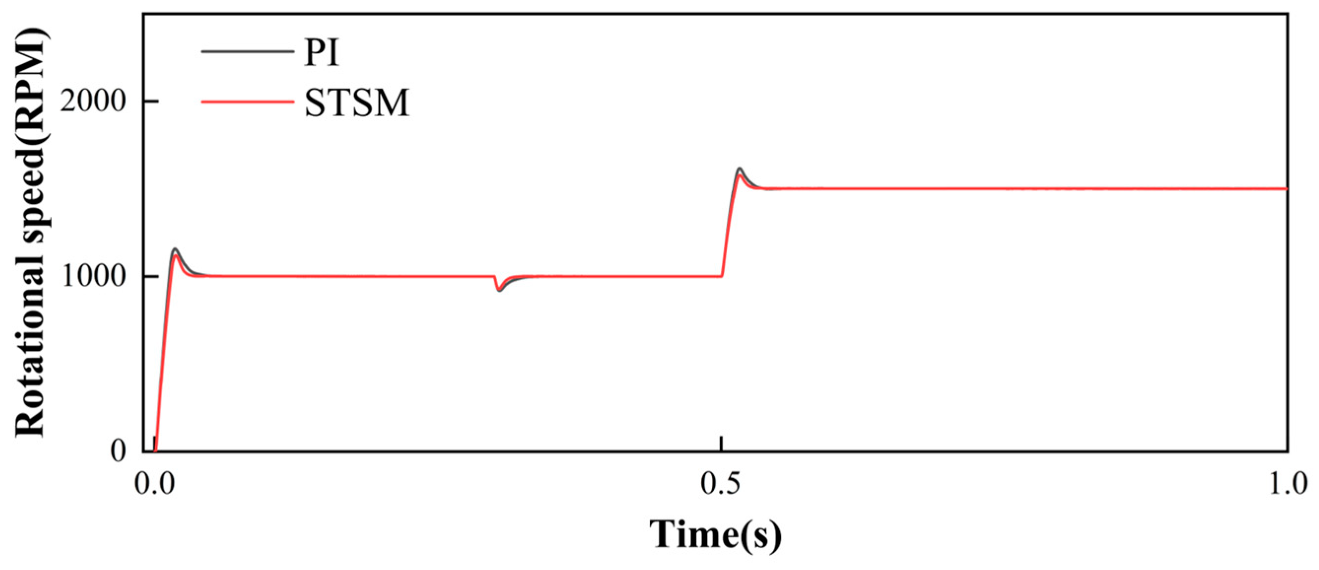
5.1. Feasibility Analysis

This section conducts feasibility simulation experiments to validate the performance of the super-helical sliding mode model reference adaptive control system proposed in this paper. The initial operating speed of the motor is set at 1000 r/min, while the initial load torque is 10 N∙m. At 0.3 s into the simulation, the load torque abruptly transitions to 20 N∙m. Similarly, at 0.5 s, another abrupt change occurs where the load torque shifts to 20 N∙m. Additionally, at the 0.5 s mark, the motor speed undergoes an abrupt change to 1500 r/min.
To validate the effectiveness and robustness of the proposed control strategy, a pulse disturbance module was introduced at the torque input, generating a pulse signal with an amplitude of 5 at 0.1 s intervals. Furthermore, the motor stator resistance was treated as an uncertain parameter, with a 10% increment at 0.5 s to emulate the effects of internal aging. These configurations were designed to rigorously assess the strategy’s resilience under external disturbances and model uncertainties.
Figure 6 presents the motor speed simulation waveforms corresponding to both the STSM-MRAS and traditional PI control systems when abrupt changes in motor speed and load occur. Figure 7 illustrates the speed error simulation waveforms corresponding to the STSM-MRAS and traditional PI control systems under similar conditions. Figure 8 exhibits the simulated waveforms of rotor position error for the STSM-MRAS and conventional PI control systems during abrupt changes in motor speed and load. Figure 9 illustrates the simulated motor speed error waveforms for the STSM-MARS and conventional PI-MARS control systems when subjected to external disturbances and model uncertainties.
Motor speed overshoot refers to the maximum extent by which the actual speed exceeds its steady-state value when the motor responds to an input signal (such as a step signal or load change). In control system design, managing the overshoot is critical. Excessive overshoot can result in system instability or damage to equipment, while a moderate amount of overshoot can improve the system’s response speed. The calculation method is shown in Equation (49), where MN represents the speed overshoot, Nmax is the maximum speed, and Nss is the steady-state speed.
M N = N max N s s
As depicted in Figure 7, upon motor initialization, the STSM-MARS control system proposed in this paper exhibits an overshoot of 119 r/min, reaching a steady state in 0.036 s. Conversely, the conventional PI-MARS control system experiences an overshoot of 157 r/min, requiring 0.062 s to reach a steady state. The motor startup behavior aligns similarly with that of the conventional PI-MARS control system, attaining a steady state in 0.062 s. At 0.3 s, during the load surge of 20 N, the speed of the STSM-MARS control system decreases by 70 r/min, whereas the conventional PI-MARS control system registers a decrease of 82 r/min. Subsequently, at 0.5 s, during the speed surge, the overshoot of the STSM-MARS control system amounts to 77 r/min, while the conventional PI-MARS control system exhibits an overshoot of 116 r/min. This formulation provides a comparative analysis of the performance of the STSM-MARS and conventional PI-MARS control systems during motor startup, load surge, and speed surge scenarios.
As illustrated in Figure 8, during motor startup, the speed error of the STSM-MARS control system proposed in this paper is 31 r/min, whereas the speed error of the conventional PI-MARS control system is 45 r/min. At 0.3 s, during the load surge of 20 N, the speed error of the STSM-MARS control system is −0.002 rad, while that of the conventional PI-MARS control system is −0.006 rad. Subsequently, at 0.5 s, during the speed surge, the speed error of the STSM-MARS control system amounts to 20 r/min, reaching a steady state at 26 r/min, whereas the conventional PI-MARS control system takes additional time to achieve a steady state, with a speed error of 26 r/min. This comparison elucidates the speed error performance of both the STSM-MARS and conventional PI-MARS control systems during motor startup, load surge, and speed surge events, as depicted in Figure 6.
As depicted in Figure 9, upon motor initialization, the rotor position error of the STSM-MARS control system proposed in this paper is 0.012 rad, whereas the rotor position error of the conventional PI-MARS control system is 0.036 rad. At 0.3 s, when the load abruptly increases to 20 N, and there is a sudden increase in speed, the rotor position error of the STSM-MARS control system is −13 r/min, while the rotor position error of the conventional PI-MARS control system is −17 r/min. Similarly, at 0.5 s, the rotor position error of the STSM-MARS control system is 0.009 rad, while the rotor position error of the conventional PI-MARS control system is 0.019 rad. This comparison elucidates the rotor position error performance of both the STSM-MARS and conventional PI-MARS control systems during motor startup, load surge, and speed surge events.
As illustrated in Figure 10, under external disturbances and model uncertainties, the proposed STSM-MARS control system outperforms the conventional PI-MARS control system by achieving significantly smaller rotor speed error and faster convergence to steady-state conditions.
Compared to the conventional PI-MARS algorithm, the STSM-MRAS algorithm demonstrates a capacity for diminishing rotor speed fluctuation and position estimation errors while achieving quicker convergence toward zero. This observation suggests that the STSM-MRAS algorithm exhibits superior steady-state performance and robustness compared to the traditional PI-MARS algorithm.

5.2. Optimization Results

To evaluate the performance of the two sets of proposed super-helical sliding mode model reference adaptive systems (STSM-MRAS) in optimizing design, simulations were conducted with the motor’s initial operating speed set at 1000 r/min and subjected to an initial load torque of 10 N∙m. At 0.5 s into the simulation, an abrupt change occurred, causing the motor speed to transition to 3500 r/min.
Figure 11 displays the simulated waveforms of motor speed corresponding to the two optimization algorithms when a sudden change in motor speed occurs. Likewise, Figure 9 illustrates the simulated waveforms of motor torque corresponding to the two optimization algorithms under the same conditions. Furthermore, Figure 10 exhibits the Z-curve plots of the standard evaluation of PSSEE complementary to the two optimization algorithms during a sudden change in motor speed.
As depicted in Figure 11, the motor’s speed overshoot is notably reduced under both optimization algorithms. Specifically, in Figure 11a, employing the NSGA-II optimization algorithm, the initial rotational speed overshoot decreases from 138 r/min with the initial STSM algorithm to 124 r/min. Similarly, at 0.5 s, the rotational speed overshoot decreases from 118 r/min to 85 r/min. In Figure 11b, utilizing the MOPSO optimization algorithm, the initial rotational speed overshoot decreases from 138 r/min to 112 r/min with the initial STSM algorithm. Correspondingly, at 0.5 s, the rotational speed overshoot diminishes from 118 r/min to 73 r/min. Notably, the time taken to reach a steady state remains consistent across all scenarios. Calculations demonstrate that under the NSGA-II and MOPSO optimization algorithms, the speed overshoot of the permanent magnet synchronous motor decreases by 27.97% and 38.13% during sudden speed changes and by 10.15% and 18.84% during startup, respectively.
The torque overshoot measures the degree to which the output torque of the motor surpasses its steady-state value in response to dynamic stimuli. The calculation methodology is delineated in Equation (50), where MT represents the torque overshoot, Tmax denotes the peak torque, and Tss signifies the steady-state torque.
M T = T max T s s
As depicted in Figure 12, the overshooting of the motor torque has significantly decreased through the optimization of both algorithms. In Figure 12a, under the NSGA-II optimization algorithm, the motor torque overshoot decreases from 40.42 N to 37.25 N during motor startup and from 38 N to 33.98 N during the 0.5 s speed mutation. In Figure 12b, employing the MOPSO optimization algorithm, the torque overshoot during motor startup decreases from 40.42 N to 37.15 N, and the motor torque overshoot diminishes from 38 N to 33.95 N at 0.5 s of sudden speed change. Calculations reveal that the torque overshoot of the permanent magnet synchronous motor decreases by 7.8% and 8.1% during sudden speed changes and by 10.57% and 10.66% during startup under the NSGA-II and MOPSO optimization algorithms, respectively.
Based on the simulation data and calculations, it is evident that the MOPSO optimization algorithm proves more effective in reducing both speed and torque overshoot compared to the NSGA-II algorithm. However, the performance of the two algorithms remains comparable. Therefore, the Shannon entropy-based PSSEE introduced in this paper can be further utilized to analyze the effect of torque overshoot reduction under both optimization algorithms. This formulation underscores the potential of the PSSEE methodology in providing deeper insights into the performance nuances between different optimization strategies. This statement emphasizes the significance of utilizing the PSSEE methodology for a comprehensive assessment of the torque overshoot reduction effects under various optimization algorithms.
Figure 13 illustrates the motor’s performance based on PSSEE evaluation criteria through a Z-score plot. It is evident from the figure that the maximum value of the Z-score plot has decreased for both optimization algorithms. Specifically, the Zmax value for the NSGA-II optimization algorithm, initially falling in the C7 interval, reduces to 5.75, while for the MOPSO optimization algorithm, also in the C7 interval, decreases to 5.36. These results demonstrate that both novel optimization algorithms, compared with STSM, effectively reduce torque aggregation.
Moreover, MOPSO exhibits a lower Z-score and a more reasonable torque aggregation distribution, which is conducive to prolonging the motor’s life and enhancing its performance. Utilizing the Z-score of PSSEE allows for a more reasonable and efficient evaluation of the motor’s torque, ultimately leading to the judgment of MOPSO as a more effective optimization algorithm. This analysis underscores the advantages of employing the PSSEE methodology for evaluating motor performance and highlights MOPSO’s superiority in optimizing torque aggregation and overall motor performance.

6. Conclusions

Adaptive control strategies have been widely applied in the field of motor control. However, traditional adaptive control methods often suffer from poor robustness and slow response speed. To address these issues, the Hyper-Sliding Mode Control was introduced into the traditional adaptive control strategy, constructing an adaptive motor control system. To comprehensively evaluate the motor’s output torque, the PSSEE was proposed, which effectively reflects the distribution of output torque across different ranges, helping to identify superior optimization algorithms. Furthermore, the NSGA-II and the MOPSO were employed to optimize the control parameters of the system and joint simulations were conducted using the Isight software and Simulink to verify the motor’s performance. Simulation results show that, compared to traditional adaptive control strategies, the proposed control strategy improves the motor’s steady-state response speed by 42% and reduces rotor error during system fluctuations by 23%, significantly enhancing the motor’s response speed and robustness. After parameter optimization, the system’s speed and torque overshoot decreased by 38% and 10%, respectively, further improving the stability and accuracy of the motor control system. The introduction of super-helical sliding mode control and optimization algorithms into adaptive control systems offers an efficient approach to enhancing the robustness, stability, and accuracy of motor control systems. Additionally, the PSSEE provides a more intuitive representation of output torque and is equally valuable equal value in the domain of new energy vehicles. Future research will concentrate on the following aspects:
(1)
The consideration of additional aspects of motor performance as constraints within the optimization algorithms, such as vibration levels and response speeds.
(2)
Incorporating hardware experiments based on theoretical analysis to strengthen the persuasiveness of the control strategy and optimization design.
(3)
Exploring the integration of the novel sliding mode control strategy with other control approaches.

Author Contributions

Conceptualization, L.K.; Methodology, L.K.; Software, L.K.; Formal analysis, L.K.; Data curation, L.K., H.Z., T.Z., J.W. and C.Y.; Writing—original draft, L.K.; Writing—review & editing, H.Z., T.Z., J.W., C.Y. and Z.Z.; Visualization, L.K. and H.Z.; Supervision, H.Z., T.Z., J.W., C.Y. and Z.Z.; Project administration, H.Z., T.Z. and C.Y.; Funding acquisition, H.Z., T.Z. and C.Y. All authors have read and agreed to the published version of the manuscript.

Funding

The project is supported partly by the National Natural Science Foundation of China (No. 52075278).

Data Availability Statement

The original contributions presented in the study are included in the article, further inquiries can be directed to the corresponding author.

Conflicts of Interest

Author Chaohui Yang was employed by the company Qingte Group Limited. The remaining authors declare that the re-search was conducted in the absence of any commercial or financial relationships that could be construed as a potential conflict of interest.

References

  1. Zhang, Z.; Zhang, T.; Hong, J.; Zhang, H.; Yang, J. Energy Management Strategy of a Novel Parallel Electric-Hydraulic Hybrid Electric Vehicle Based on Deep Reinforcement Learning and Entropy Evaluation. J. Clean. Prod. 2023, 403, 136800. [Google Scholar] [CrossRef]
  2. Yang, J.; Zhang, T.; Hong, J.; Zhang, H.; Zhao, Q.; Meng, Z. Research on Driving Control Strategy and Fuzzy Logic Optimization of a Novel Mechatronics-Electro-Hydraulic Power Coupling Electric Vehicle. Energy 2021, 233, 121221. [Google Scholar] [CrossRef]
  3. Sun, Z.; Deng, Y.; Wang, J.; Li, H.; Cao, H. Improved Cascaded Model-Free Predictive Speed Control for PMSM Speed Ripple Minimization Based on Ultra-Local Model. ISA Trans. 2023, 143, 666–677. [Google Scholar] [CrossRef] [PubMed]
  4. Wang, M.; Liu, Y.; Wang, Q.; Liao, Y.; Wheeler, P. Speed-Current Single-Loop Control of PMSM Based on Model-Assisted Cascaded Extended State Observer and Sliding Mode Control. Int. J. Circuit Theory Appl. 2024, 52, 3558–3583. [Google Scholar] [CrossRef]
  5. Kumar, K.B.; Praveen Kumar, K.V. An Enhanced Predictive Current Control Technique for Interior Permanent Magnet Synchronous Motor Drives with Extended Voltage Space Vectors for Electric Vehicles. Int. J. Circuit Theory Appl. 2024, 52, 4234–4253. [Google Scholar] [CrossRef]
  6. Guo, Q.; Pan, T.; Liu, J.; Chen, S. Explicit Model Predictive Control of Permanent Magnet Synchronous Motors Based on Multi-Point Linearization. Trans. Inst. Meas. Control 2021, 43, 2872–2881. [Google Scholar] [CrossRef]
  7. Hezzi, A.; Bensalem, Y.; Ben Elghali, S.; Naceur Abdelkrim, M. Sliding Mode Observer Based Sensorless Control of Five Phase PMSM in Electric Vehicle. In Proceedings of the 2019 19th International Conference on Sciences and Techniques of Automatic Control and Computer Engineering (STA), Sousse, Tunisia, 24–26 March 2019; pp. 530–535. [Google Scholar]
  8. Houari, A.; Bouabdallah, A.; Djerioui, A.; Machmoum, M.; Auger, F.; Darkawi, A.; Olivier, J.-C.; Benkhoris, M.F. An Effective Compensation Technique for Speed Smoothness at Low-Speed Operation of PMSM Drives. IEEE Trans. Ind. Appl. 2018, 54, 647–655. [Google Scholar] [CrossRef]
  9. Zhao, K.; Dai, W.; Wu, S.; Qiu, P.; Liu, W.; Huang, G. Improved Super-Twisting-Observer-Based Finite-Control-Set Model-Predictive Fault-Tolerant Current Control of PMSM Considering Demagnetization Fault. Int. J. Electr. Power Energy Syst. 2022, 142, 108325. [Google Scholar] [CrossRef]
  10. Liu, Y.-C.; Laghrouche, S.; Depernet, D.; Djerdir, A.; Cirrincione, M. Disturbance-Observer-Based Complementary Sliding-Mode Speed Control for PMSM Drives: A Super-Twisting Sliding-Mode Observer-Based Approach. IEEE J. Emerg. Sel. Top. Power Electron. 2021, 9, 5416–5428. [Google Scholar] [CrossRef]
  11. Zhang, L.; Li, H.; Shan, L.; Zhang, L.; Zhang, L. Double-Hierarchical Fuzzy Exponential Convergence Law Fractional-Order Sliding Mode Control for PMSM Drive Control in EV. Eng. Sci. Technol. Int. J. 2023, 47, 101536. [Google Scholar] [CrossRef]
  12. Xiuping, W.; Juxin, Z.; Chunyu, Q. Based on the Super-Helical Sliding Mode Algorithm PMLSM Sensorless Control. In Proceedings of the 2024 IEEE 3rd International Conference on Electrical Engineering, Big Data and Algorithms (EEBDA), Changchun, China, 27–29 February 2024; pp. 96–99. [Google Scholar]
  13. Zhao, K.; Liu, W.; Zhou, R.; Dai, W.; Wu, S.; Qiu, P.; Yin, Y.; Jia, N.; Yi, J.; Huang, G. Model-Free Fast Integral Terminal Sliding-Mode Control Method Based on Improved Fast Terminal Sliding-Mode Observer for PMSM with Unknown Disturbances. ISA Trans. 2023, 143, 572–581. [Google Scholar] [CrossRef]
  14. Gabbi, T.S.; de Araujo, M.B.; Rocha, L.R.; Scalcon, F.P.; Gründling, H.A.; Vieira, R.P. Discrete-Time Sliding Mode Controller Based on Backstepping Disturbance Compensation for Robust Current Control of PMSM Drives. ISA Trans. 2022, 128, 581–592. [Google Scholar] [CrossRef] [PubMed]
  15. Huang, M.; Deng, Y.; Li, H.; Wang, J. Torque Ripple Attenuation of PMSM Using Improved Robust Two-Degree-of-Freedom Controller via Extended Sliding Mode Parameter Observer. ISA Trans. 2022, 129, 558–571. [Google Scholar] [CrossRef] [PubMed]
  16. Shweta, B.; Sadhana, V. Model Predictive Control and Higher Order Sliding Mode Control for Optimized and Robust Control of PMSM. IFAC-PapersOnLine 2022, 55, 195–200. [Google Scholar] [CrossRef]
  17. Xu, X.; Han, Q. A General Electromagnetic Model and Vibration Control for Shape Deviations in PMSM Supported by Three-Pole Active Magnetic Bearings. Mech. Syst. Signal Process. 2021, 158, 107710. [Google Scholar] [CrossRef]
  18. Zhang, Q.; Guo, H.; Liu, Y.; Guo, C.; Lu, K.; Wang, D.; Zhang, Z.; Sun, J. Robust Plug-in Repetitive Control for Speed Smoothness of Cascaded-PI PMSM Drive. Mech. Syst. Signal Process. 2022, 163, 108090. [Google Scholar] [CrossRef]
  19. Obeid, H.; Fridman, L.M.; Laghrouche, S.; Harmouche, M. Barrier Function-Based Adaptive Sliding Mode Control. Automatica 2018, 93, 540–544. [Google Scholar] [CrossRef]
  20. Cruz-Ancona, C.D.; Fridman, L.; Obeid, H.; Laghrouche, S.; Pérez-Pinacho, C.A. A Uniform Reaching Phase Strategy in Adaptive Sliding Mode Control. Automatica 2023, 150, 110854. [Google Scholar] [CrossRef]
  21. Cruz-Ancona, C.D.; Estrada, M.A.; Fridman, L. Barrier Function-Based Adaptive Lyapunov Redesign for Systems Without A Priori Bounded Perturbations. IEEE Trans. Autom. Control 2022, 67, 3851–3862. [Google Scholar] [CrossRef]
  22. González, A.; Ovalle, L.; Fridman, L. Final Set Adjustment in Barrier Function Adaptation Exploiting Properties of Signed Power-Based Controllers. IEEE Trans. Autom. Control 2024, 69, 5486–5491. [Google Scholar] [CrossRef]
  23. Plestan, F.; Shtessel, Y.; Brégeault, V.; Poznyak, A. New Methodologies for Adaptive Sliding Mode Control. Int. J. Control 2010, 83, 1907–1919. [Google Scholar] [CrossRef]
  24. Utkin, V.I.; Poznyak, A.S. Adaptive Sliding Mode Control with Application to Super-Twist Algorithm: Equivalent Control Method. Automatica 2013, 49, 39–47. [Google Scholar] [CrossRef]
  25. Franco, R.; Ríos, H.; de Loza, A.F.; Efimov, D. A Robust Nonlinear Model Reference Adaptive Control for Disturbed Linear Systems: An LMI Approach. IEEE Trans. Autom. Control 2022, 67, 1937–1943. [Google Scholar] [CrossRef]
  26. Shtessel, Y.; Plestan, F.; Edwards, C.; Levant, A. Adaptive Sliding Mode and Higher Order Sliding-Mode Control Techniques with Applications: A Survey. In Sliding-Mode Control and Variable-Structure Systems: The State of the Art; Oliveira, T.R., Fridman, L., Hsu, L., Eds.; Springer International Publishing: Cham, Switzerland, 2023; pp. 267–305. [Google Scholar]
  27. Khanh, P.Q.; Anh, H.P.H. Advanced PMSM Speed Control Using Fuzzy PI Method for Hybrid Power Control Technique. Ain Shams Eng. J. 2023, 14, 102222. [Google Scholar] [CrossRef]
  28. Zhang, C.; Zhang, L.; Wang, D.; Lu, K. A Smith-Predictor-Assisted Adaptive Load Disturbance Rejection Controller for Speed Variation Suppression of PMSM Drive. Int. J. Electr. Power Energy Syst. 2024, 155, 109666. [Google Scholar] [CrossRef]
  29. Xu, G.; Luo, K.; Jing, G.; Yu, X.; Ruan, X.; Song, J. On Convergence Analysis of Multi-Objective Particle Swarm Optimization Algorithm. Eur. J. Oper. Res. 2020, 286, 32–38. [Google Scholar] [CrossRef]
  30. Verma, S.; Pant, M.; Snasel, V. A Comprehensive Review on NSGA-II for Multi-Objective Combinatorial Optimization Problems. IEEE Access 2021, 9, 57757–57791. [Google Scholar] [CrossRef]
  31. Gao, Y.; Yang, T.; Bozhko, S.; Wheeler, P.; Dragicevic, T.; Gerada, C. Neural Network Aided PMSM Multi-Objective Design and Optimization for More-Electric Aircraft Applications. Chin. J. Aeronaut. 2022, 35, 233–246. [Google Scholar] [CrossRef]
  32. Srivastava, A. An Application of Kho-Kho Optimization Algorithm to Estimation Parameter of Permanent Magnet Synchronous Machine. E-Prime-Adv. Electr. Eng. Electron. Energy 2023, 6, 100309. [Google Scholar] [CrossRef]
  33. Yousri, D.; Allam, D.; Eteiba, M.B. Chaotic Whale Optimizer Variants for Parameters Estimation of the Chaotic Behavior in Permanent Magnet Synchronous Motor. Appl. Soft Comput. 2019, 74, 479–503. [Google Scholar] [CrossRef]
  34. Sun, C.; Wen, F.; Xiong, W.; Wang, H.; Shang, H. Multi-Objective Comprehensive Teaching Algorithm for Multi-Objective Optimisation Design of Permanent Magnet Synchronous Motor. IET Electr. Power Appl. 2020, 14, 2564–2576. [Google Scholar] [CrossRef]
  35. Wang, B.; Zhu, J.; Li, Z.; Li, Y. An Optimization Algorithm Used in PMSM Model Predictive Control. IEICE Electron. Express 2024, 21, 20230444. [Google Scholar] [CrossRef]
  36. Liu, M.; Zhang, H.; Yang, J.; Zhang, T.; Zhang, C.; Bo, L. A Path Planning Algorithm for Three-Dimensional Collision Avoidance Based on Potential Field and B-Spline Boundary Curve. Aerosp. Sci. Technol. 2024, 144, 108763. [Google Scholar] [CrossRef]
  37. Elsherbiny, H.; Szamel, L.; Ahmed, M.K.; Elwany, M.A. High Accuracy Modeling of Permanent Magnet Synchronous Motors Using Finite Element Analysis. Mathematics 2022, 10, 3880. [Google Scholar] [CrossRef]
Figure 1. Equivalent circuit diagram in d-q coordinates.
Applsci 14 10967 g001
Figure 2. Standardized feedback systems.
Applsci 14 10967 g002
Figure 3. Planetary gear and working modes.
Applsci 14 10967 g003
Figure 4. Block diagram of permanent magnet synchronous motor control using the STSM control method.
Applsci 14 10967 g004
Figure 5. Block diagram of the two optimization algorithms NSGA-II and MOPSO.
Applsci 14 10967 g005
Figure 6. The convergence curve of the parameter.
Applsci 14 10967 g006
Figure 7. Motor speed results.
Applsci 14 10967 g007
Figure 8. Motor speed error results.
Applsci 14 10967 g008
Figure 9. Rotor position error results.
Applsci 14 10967 g009
Figure 10. Motor speed error results.
Applsci 14 10967 g010
Figure 11. Motor speed results in sudden speed changes.
Applsci 14 10967 g011
Figure 12. Motor speed results during sudden speed changes.
Applsci 14 10967 g012
Figure 13. The Z-curve plot of standardized evaluation of PSSEE.
Applsci 14 10967 g013
Table 1. Parameterization.
Parameter NameValue
Population size10
Generational scale20
Crossover probability0.9
Cross-distribution index 10
Variation distribution index 20
Table 2. Parameterization.
Parameter NameValue
Maximum Iterations20
Number of Particles10
Inertia0.9
Global Increment 0.9
Particle Increment0.9
Maximum Velocity0.1
Disclaimer/Publisher’s Note: The statements, opinions and data contained in all publications are solely those of the individual author(s) and contributor(s) and not of MDPI and/or the editor(s). MDPI and/or the editor(s) disclaim responsibility for any injury to people or property resulting from any ideas, methods, instructions or products referred to in the content.

