Abstract
The vortex-induced vibration of a circular cylinder and two inline circular cylinders near a plane wall at a Reynolds number of 150 is numerically investigated by using a self-developed immersed boundary method called the local domain-free discretization (DFD) method. The cylinders are elastically mounted with a mass ratio of and a 0 damping ratio and can only vibrate in the transverse direction. The reduced velocity varies from 2 to 9, with an interval of 1. Three gaps, , , and ( is the cylinder diameter), are investigated for the case of an isolated cylinder and two inline cylinders while the center-to-center spacing () is for the two-inline-cylinders case. A model for the collision of the cylinders with the wall is adopted in which the bouncing back is forced when the gap between the cylinder and the plane wall is smaller than 0.02. It is observed that the existence of the plane wall significantly affects the cylinder response both in the one-isolated-cylinder and two-inline-cylinders cases. The features, including vibration amplitudes, frequencies, fluid forces, the maximal or minimal gap between the cylinder bottom and the plane wall, and the vortex shedding patterns, are explored in detail. Interactions between the front and rear cylinders and differences between the one-isolated-cylinder and two-inline-cylinders cases are discussed. The research has immense significance for the design of near-wall cylindrical structures, such as the deep-water pipeline system on the seafloor.
1. Introduction
The vortex-induced vibration (VIV) of cylindrical structures has been regarded as a significant cause of structure damage in many engineering fields [1,2], such as offshore structures, civil engineering, heat exchange devices, etc. The VIV phenomenon involves complicated physical mechanisms and extensive studies and reviews have emerged over the past several decades, considering various aspects of VIV [3,4,5,6].
Most previous research is focused on the paradigm of an elastically mounted, wall-free (i.e., wall-proximity effects are ignored) cylinder. It has been shown that the VIV characteristics depend on several variables, including the mass ratio (the ratio of cylinder mass to the displaced fluid mass), the damping ratio (the ratio of the damping coefficient to critical damping coefficient), and the reduced velocity (, where is the freestream velocity, is the damped natural frequency of the structure, and is the cylinder diameter) [3]. Khalak and Williamson [7] categorized the cylinder response into two types based on the magnitude of . For a low , the response curve has three branches when plotted versus , named the ‘initial’, ‘upper’, and ‘lower’ branches. However, for a high , the ‘upper’ one does not exist anymore. There are many vortex shedding flow patterns in the cylinder wake region, such as ‘2S’ (two single vortices formed per cycle), ‘2P’ (two pairs of vortices formed per cycle), and ‘2T’ (two triplets of vortices per cycle). Various response branches may be associated with vortex shedding mode characteristics. Earlier research revealed that the initial branch corresponds to the ‘2S’ mode while a ‘2P’ mode appears in the upper and lower branches [8,9].
In engineering practices, near-wall cylindrical structures are commonly encountered. For example, the deep-water pipeline system traversing over the seafloor (Figure 1a,b) or the flat-bottomed ground-supported silos used for storing granular-like material (Figure 1c). These cylindrical structures may suffer from fluid dynamics and can develop different buckling modes [10], including elephant foot buckling [11], top-of-wall damage buckling [12], and elastic buckling [13]. These can all be regarded as near-wall cylinders. In this paper, the VIV of the rigid cylindrical structures near a plane wall is considered, which is often seen in the deep-water pipeline system (Figure 1a,b). Compared to the case of a wall-free cylinder, the flow behind the near-wall cylinder will become much more complex due to the interactions between the wall boundary layer and the shear layer over the cylinder. In the VIV of the near-wall cylinder, the gap ratio ( the gap between the bottom of the cylinder and the wall) is a crucial parameter. A few recent studies have been focused on the VIV of a circular cylinder close to a plane boundary. Tham et al. [14] conducted a numerical study on the wall effects at for and they found that the lock-in region became larger for a lower . Chen and Wu [15] performed the numerical simulations of a near-wall cylinder with small gap ratios () at and they found that the largest amplitude and the natural frequency of the cylinder and the vortex shedding from the cylinder are significantly affected by the wall. De and Sarker [16] identified C (chaotic), P (periodic), and QP (quasi-periodic) vortex shedding modes at two and mass ratios for a circular cylinder undergoing VIV near a solid wall. These studies of the VIV of a circular cylinder near a stationary wall can serve as a foundation to improve pipeline design guidelines [17].
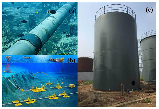
Figure 1.
Examples of near-wall cylindrical structures in engineering practices. (a,b): deep-water pipeline system; (c): flat-bottomed ground-supported silos.
In addition, many engineering structures are in arrays, such as bridge piers, groups of chimney stacks, bridge pier offshore platforms, etc. Unlike the single freely vibrated cylinder, the vibration of a cylinder in a tandem-arrangement system is affected not only by its own vortex shedding but also by the vortex generated by the adjacent cylinder [18]. Zdravkovich [19] classified the flows around two tandem free-wall cylinders into three regimes, i.e., the extended-body regime (, with being the center to center space of two cylinders), reattachment regime (), and co-shedding regime (). In an extended-body regime, the free shear layers separated from the upstream cylinder overshoot the downstream ones. In the reattachment regime, the upstream separated shear layers reattach to the downstream cylinder. In the co-shedding regime, the shear layers roll up alternatively and form a vortex street in the gap between as well as behind the cylinders. The reattachment regime is further divided by Alam et al. [20] into two regimes based on the lift force coefficients on the cylinders: the alternating reattachment regime () and steady reattachment regime ().
To the best of the authors’ knowledge, few studies have investigated the VIV of two cylinders in a tandem arrangement close to a stationary wall, although it is highly relevant to many engineering practices, such as the free-spanning vibration of two parallel pipelines close to the sea bed. Chen et al. [21] investigated the VIV of two inline circular cylinders near a stationary wall at and . In their work, the features of vibration amplitudes, frequencies, wake patterns, fluid forces, position shifts, and vibration trajectories are explored for two gap ratios. This paper aims to investigate the differences between the VIV of a cylinder and two inline cylinders near a plane wall. In particular, the collision of the cylinder and the plane wall is considered and the cylinders can only oscillate in the transverse direction. This work can be regarded as a supplement and validation for the previous studies.
The VIV of a circular cylinder is a typical fluid-structure interaction (FSI) problem and the numerical methods can be divided into a body-fitted grid and a non-body-fitted grid. In body-fitted-grid methods, the mesh quality and computational efficiency cannot be guaranteed when the gap ratio is small. The immersed boundary (IB) method is one of the non-body-fitted-grid methods that is commonly used for solving moving-boundary problems to avoid the application of a remeshing technique. Zhou et al. [22] proposed an IB method, called the local domain-free discretization (DFD) method, in which the discrete forces that represent the wall effects are implicitly applied to the discretized Navier–Stokes (N–S) equations. In the local DFD method, some exterior nodes may be involved in the discrete form of the governing equations at a near-wall interior node. The functional solutions at these exterior dependent nodes are reconstructed by a proper local extrapolation with boundary conditions imposed. The local DFD method has been successfully applied to simulate various flows with moving boundaries [23,24]. Compared to the classical IB method pioneered by Peskin [25], the governing equations are solved only at the fluid-phase nodes in the DFD method, which will be more effective, especially for simulations of the high-Reynolds-number turbulent flows.
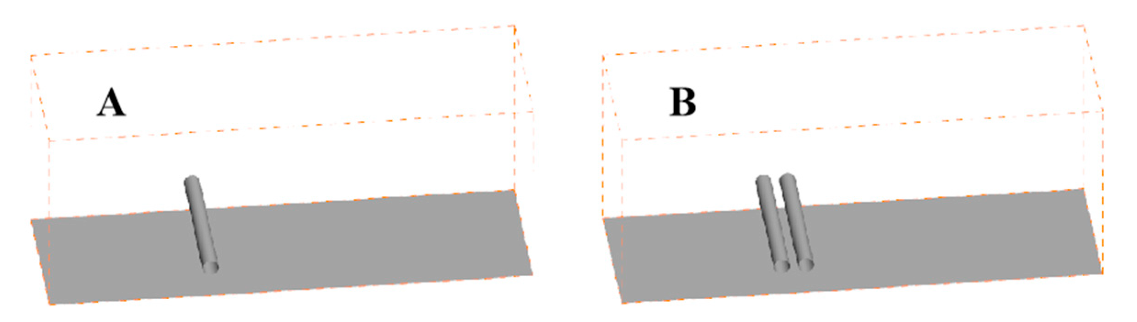
Numerical simulations of an elastically mounted circular cylinder or two in a tandem arrangement near a plane wall at a low Reynolds number are carried out in this paper. The three-dimensional schematic diagram of the investigated model is illustrated in Figure 2A,B. Due to the low Reynolds number of the flows, the three-dimensional numerical results are almost identical to the two-dimensional ones. So, only the two-dimensional VIV of cylinders is investigated in this paper. The self-developed local DFD method is employed to solve the wall boundary to allow these simulations to be conducted on a stationary mesh. The outline of the rest of this paper is arranged as follows. In Section 2, the fluid governing equations, the cylinder movement equations, and their approximations, as well as the treatment of the immersed boundary, are briefly presented. In Section 3, the validity and feasibility of the local DFD method for solving VIV problems are verified, together with a mesh convergence study. Section 4 discusses the effects of the gap ratio and the streamwise spacing ratio on the vibration amplitude, vibration frequencies, and wake patterns. Finally, the main conclusions are presented in Section 5.
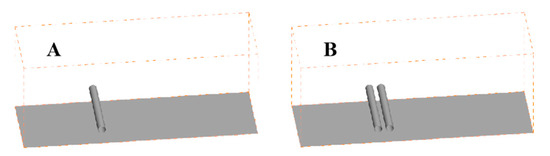
Figure 2.
Three-dimensional schematic diagram of the investigated model. (A): an isolated cylinder; (B): two inline cylinders.
2. Mathematical Model and Numerical Method
2.1. Governing Equations and Numerical Methods for Fluid
The governing equations for the two-dimensional incompressible flows with constant density and viscosity can be written as the following non-dimensional form:
where represents the gradient operator, the velocity vector, the pressure, the physical time, the Reynolds number with being the kinematic viscosity of the fluid, and the reference velocity, which is set to be the freestream velocity .
The governing equations are discretized by the Galerkin finite element approach [26] on an unstructured collocated mesh. All variables are defined at the cell vortex. A dual-time-stepping scheme [27] is employed for temporal discretization. The method of artificial compressibility is employed to reduce the disparity in sound and convective waves. In the Galerkin finite element approach, the approximation of the convective term is equivalent to the central difference and an artificial dissipation operator [27] is adopted to prevent odd–even decoupling. For more details, one can refer to [23].
2.2. The Local DFD Method
A self-developed immersed boundary method, called the local DFD method [22], is employed to deal with the moving cylinder boundaries. In this method, all the used unstructured triangular meshes are obtained by dividing the rectangular cells of the Cartesian meshes (see Figure 3) and Equations (1) and (2) are discretized at all the nodes in the fluid phase. However, the discrete form at an interior node near the wall may involve some exterior nodes. The key point of the local DFD method is how to calculate the flow variables at an exterior-dependent node, which will be described briefly here.
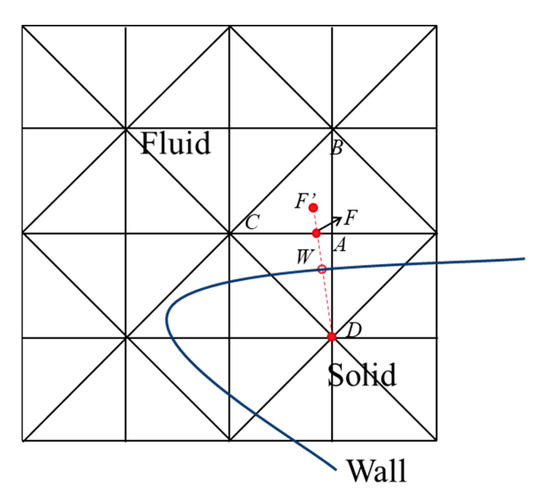
Figure 3.
Sketch map of the IB model.
A reference point in the fluid phase is first defined for the calculation of the flow variables at a given exterior-dependent node. As depicted in Figure 3, the reference point F for the exterior-dependent node D is defined to be the intersection between the wall-normal line and the interior cell edge nearest to the wall. The two vertices of the interior cell edge are interior nodes. For easy programming, the point located on the wall-normal line and with a constant distance away from the wall is set to be the corresponding reference point in the codes. The user-defined constant distance is about one local mesh interval, which makes the vertices of the host triangle the reference point located in all interior nodes, like F’ depicted in Figure 3.
In the hybrid-Cartesian immersed boundary (HCIB) method proposed by Sotiropoulos and his coworkers [28,29], a reference point is also needed to reconstruct solutions at the interior nodes in the immediate vicinity of the solid boundary. The distance of this defined reference point away from the solid wall is about twice the local mesh interval. The reference points defined both in the local DFD method and in the HCIB method are regarded as the first-layer mesh nodes. Therefore, for the same computational case, the near-wall spacing of the mesh used by the HCIB should be twice smaller than that of the mesh used by the local DFD.
The flow variables at the reference point F’ are calculated via linear interpolation over its host triangle, i.e., ABC in Figure 3. Then, the Cartesian velocity components at node D are obtained by linear extrapolation along the wall-normal direction with the no-slip boundary condition enforced:
where () represents the velocity components of the surface at W and and are the velocity components at D and F’, respectively. Solving a simplified momentum equation in the wall-normal direction and using the non-penetration at W, the pressure at D can be obtained:
where is the normal velocity of the body motion and is the pressure at F’.
2.3. Structure Motion Equations
Considering that the cylinders are elastically mounted and free to oscillate in the transverse condition only, the corresponding motion of a single cylinder is governed by the following non-dimensional equation:
where , , and are the cylinder displacement, velocity, and acceleration. in Equation (5) represents the transverse force coefficient, defined as:
with being the transverse force component, obtained from the solution of the N–S equations.
Equation (5) is solved by transforming into the following forms:
The above equations are discretized as follows:
Solving Equations (8a) and (8b), , , and can be found and they will be used as the boundary condition of the N–S equations.
The loose coupling (LC) algorithm of FSI requires low computational cost as it requires the solution of equations of fluid and structure only once at each physical time step. The FSI-LC algorithm is always applicable to high [30,31] and so the algorithm for FSI-LC presented by Borazjani et al. [32] is adopted in this paper.
2.4. Problem Setup
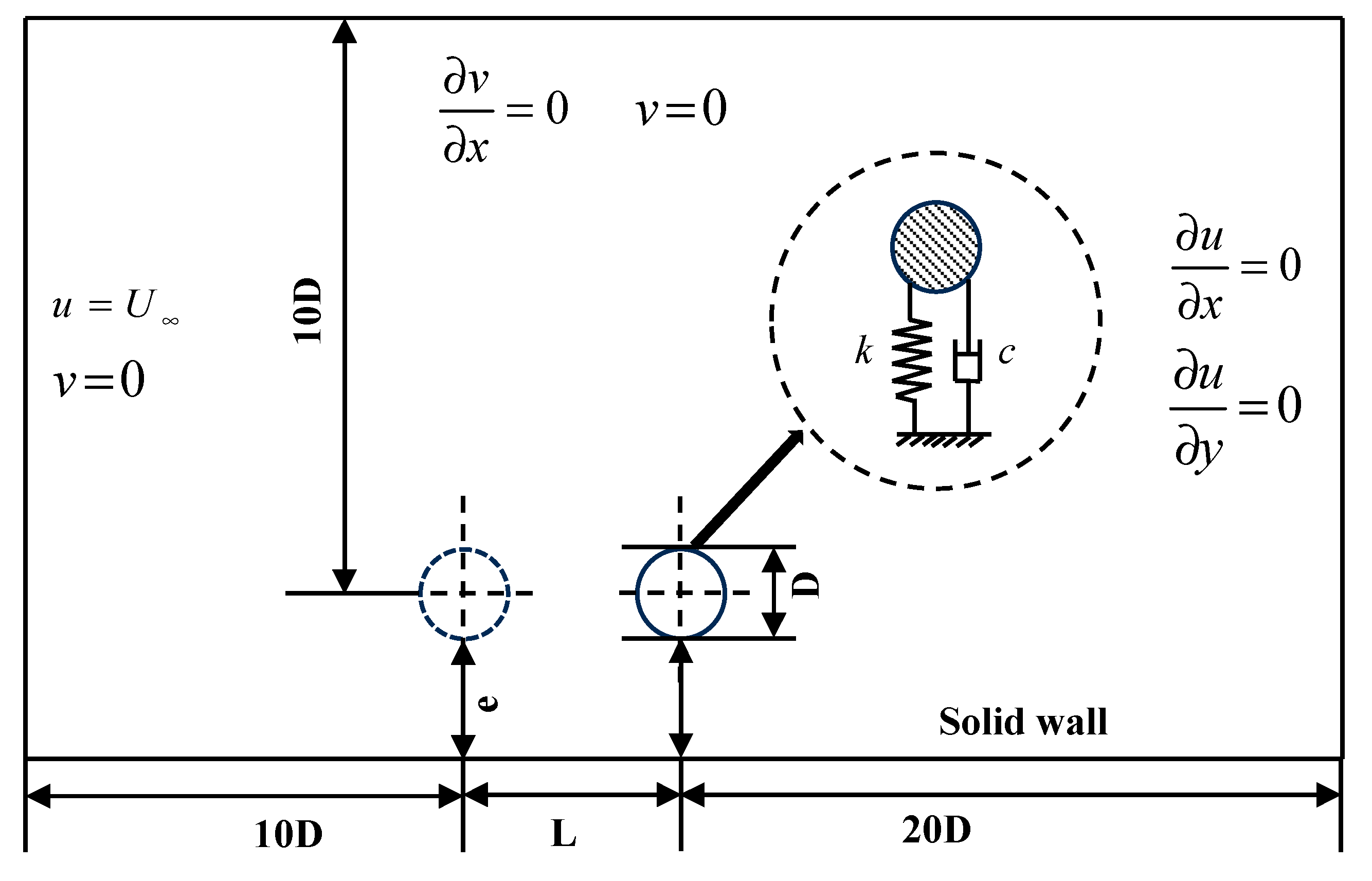
The calculation settings in this paper are simplified from the deep-water pipeline system on the seafloor. The schematic diagram of the computational model for VIV of two inline cylinders is illustrated in Figure 4. It can be seen in the figure that the whole domain is in the streamwise direction and in the transverse direction. The inflow boundary is upstream and the outflow boundary is downstream, which is consistent with the setup of a vibrating cylinder colliding with a rigid wall in Kumar and Sarkar’s work [16]. The top boundary is located at above the center of the cylinder.
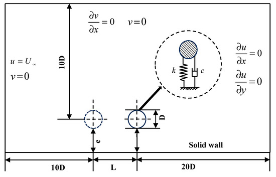
Figure 4.
Schematic diagram of the computational model.
The boundary conditions of the domain are also provided in Figure 4. The uniform flow under freestream velocity conditions is prescribed at the inflow boundary as and . Along the outlet, a Neumann-type boundary condition is employed: and . The top wall is treated as a free-slip boundary while the bottom wall is as a no-slip boundary. The cylinder surface is treated by the DFD method, with a no-slip boundary condition enforced.
The cylinder occasionally hits the plane wall, causing the cylinder to bounce back. It is assumed that the bouncing is fully elastic and changes only the vertical velocity of the cylinders. In addition, the bouncing back process is completed in one time step. That is:
where and are the vertical velocities of the cylinder before and after bouncing back and is the acceleration at that time step. With reference to the work of Chung [31] and Zhao and Cheng [33], the bouncing back is forced when the gap between the cylinder and the plane wall is smaller than 0.02.
3. Validation and Grid Dependency Study
3.1. Test of Grid Dependency
In this subsection, the grid dependency is tested by simulating a spring-mounted cylinder in an unbounded flow at the following conditions: , , , 5. The initial position of the cylinder center is set to be
to accelerate the alternative vortex shedding.
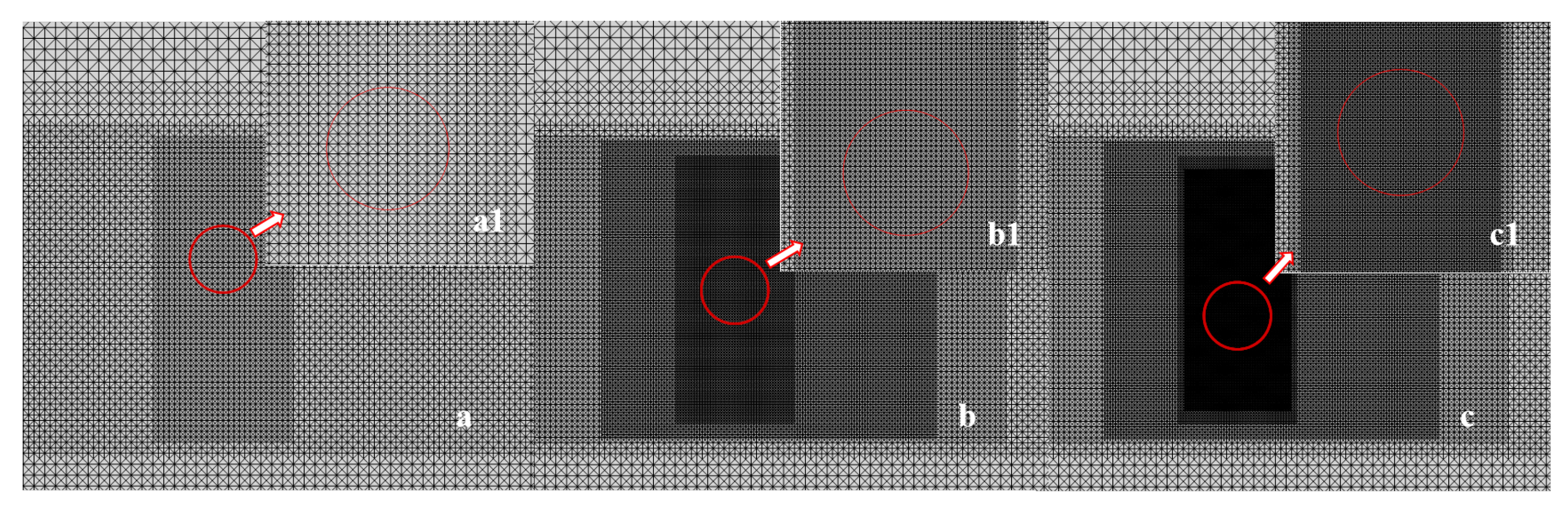
The width of the computational domain is . Approximate non-reflecting boundary conditions are constructed to improve the rate of convergence [27]. A uniform background mesh with 100 and 50 nodes in the streamwise and transverse direction is used and then it is recursively refined to obtain three different near-wall intervals, i.e., , , and . These three meshes contain 37,912, 47,761, and 90,223 nodes and are referred to as coarse, medium, and fine ones, respectively. In Figure 5, the local regions of the three different meshes are presented and it can be seen that the finest mesh cells are clustered in the region where the cylinder will pass. The simulations are carried out with dimensionless time step of .
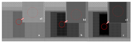
Figure 5.
Local regions of the coarse, medium, and fine mesh. (a,a1): coarse mesh and its local magnification; (b,b1): medium mesh and its local magnification; (c,c1): fine mesh and its local magnification. The circles in the figures represent the cylinder surface and the arrows mean that Figures (a1–c1) are the corresponding local magnification of Figures (a–c).
The time-averaged amplitudes , lift coefficients , and Strouhal number are listed in Table 1. The computational time per time step by using the service with Intel Xeon (R) Silver 4210R CPU @ 2.4 GHz (Intel, Santa Clara, CA, USA) is also listed in the table. It can be seen that the differences in the results diminish with mesh being refined from to . However, the computational time cost of the fine mesh is almost twice that of the medium one. Therefore, to balance the computational accuracy and efficiency, the medium grid resolution is used for all the simulations in the present work.

Table 1.
Grid independence test results at , , , and .
3.2. Validation
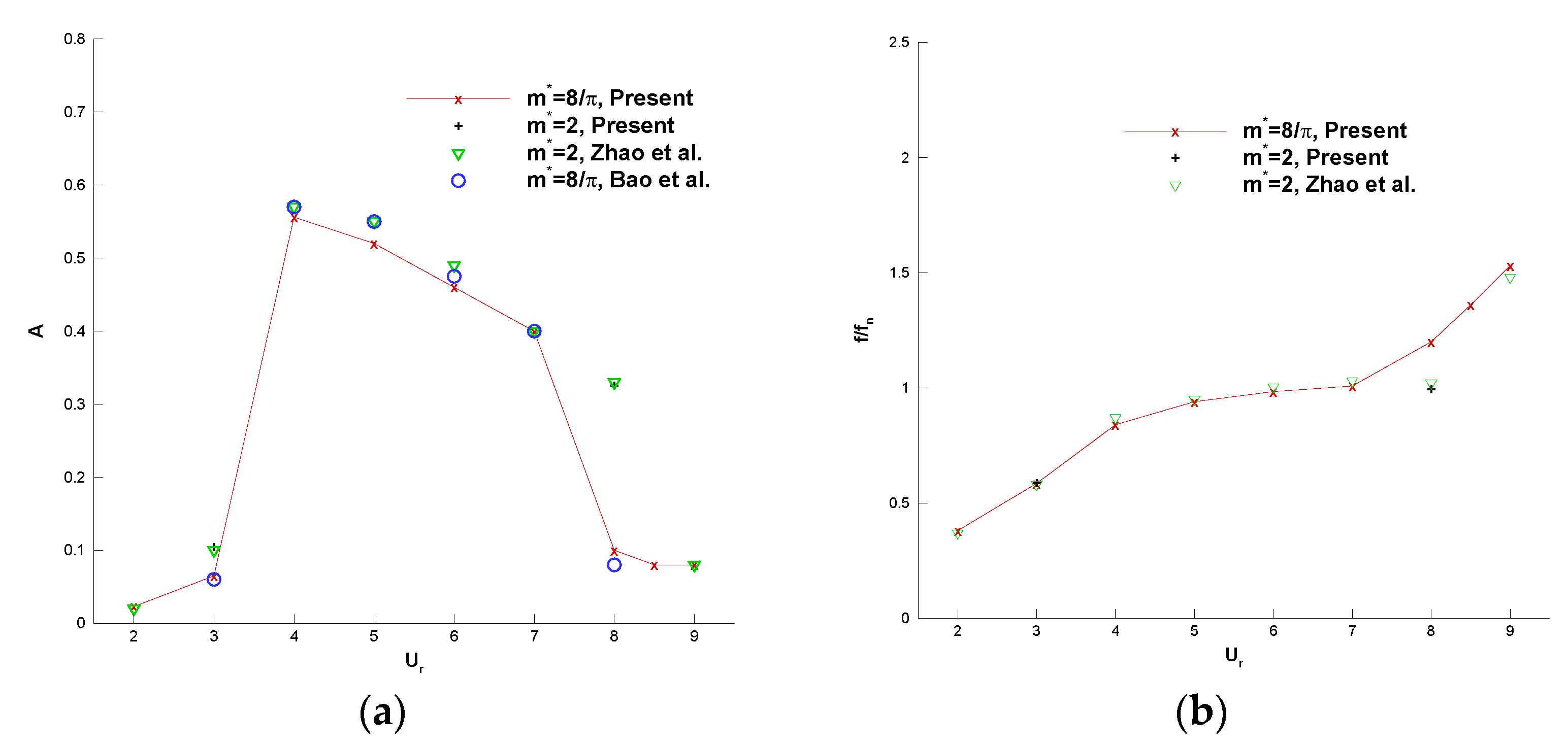
The cylinder boundaries are treated by the local DFD method and the numerical methodology is first validated by flow past a wall-free vibrating circular cylinder at , , or . The reduced velocities are varied from 2 to 9. The variation of is achieved by altering the damped natural frequency of the structure while the velocity of the freestream is maintained constant. As shown in Figure 6, the response amplitudes and their frequencies varied with are presented together with some other referenced numerical results of Bao et al. [34] or Zhao et al. [35]. The results of Bao et al. are from two-dimensional simulations while those of Zhao et al. are from three-dimensional ones.
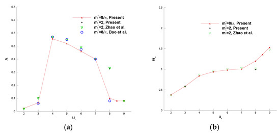
Figure 6.
Variations of the response amplitude and frequency with . (a) , (b) [34,35].
It can be seen from Figure 6 that the present results agree well with those of the referenced studies. At , the lock-in regime is between and 7; it is broadened to at . The response frequency is almost the same as the damped natural frequency inside the lock-in regime.
In addition, the current result of the maximum is compared with other numerical and experimental results in Table 2. The computational results of Ahn and Kallinderis [36] are from two-dimensional simulations and the results of Griffin [37] are from experiments. The present simulation shows good agreement in terms of the maximum with other numerical results. However, the maximum is below the experimental result, whose maximum is D. This discrepancy may be due to the different Reynolds numbers and the absence of turbulence from high-Reynolds-number flows.
Table 2.
Comparison of the current results with other numerical and experimental results.
4. Results and Discussions
4.1. VIV of a Cylinder Close to a Plane Wall
With , , and , the effects of the gap ratio on structural responses and vortex shading patterns, including their interactions, are investigated by setting , 1.0, and 2.0. To compare with the cases in unbounded flows, the reduced velocity is also varied between 2 and 9.
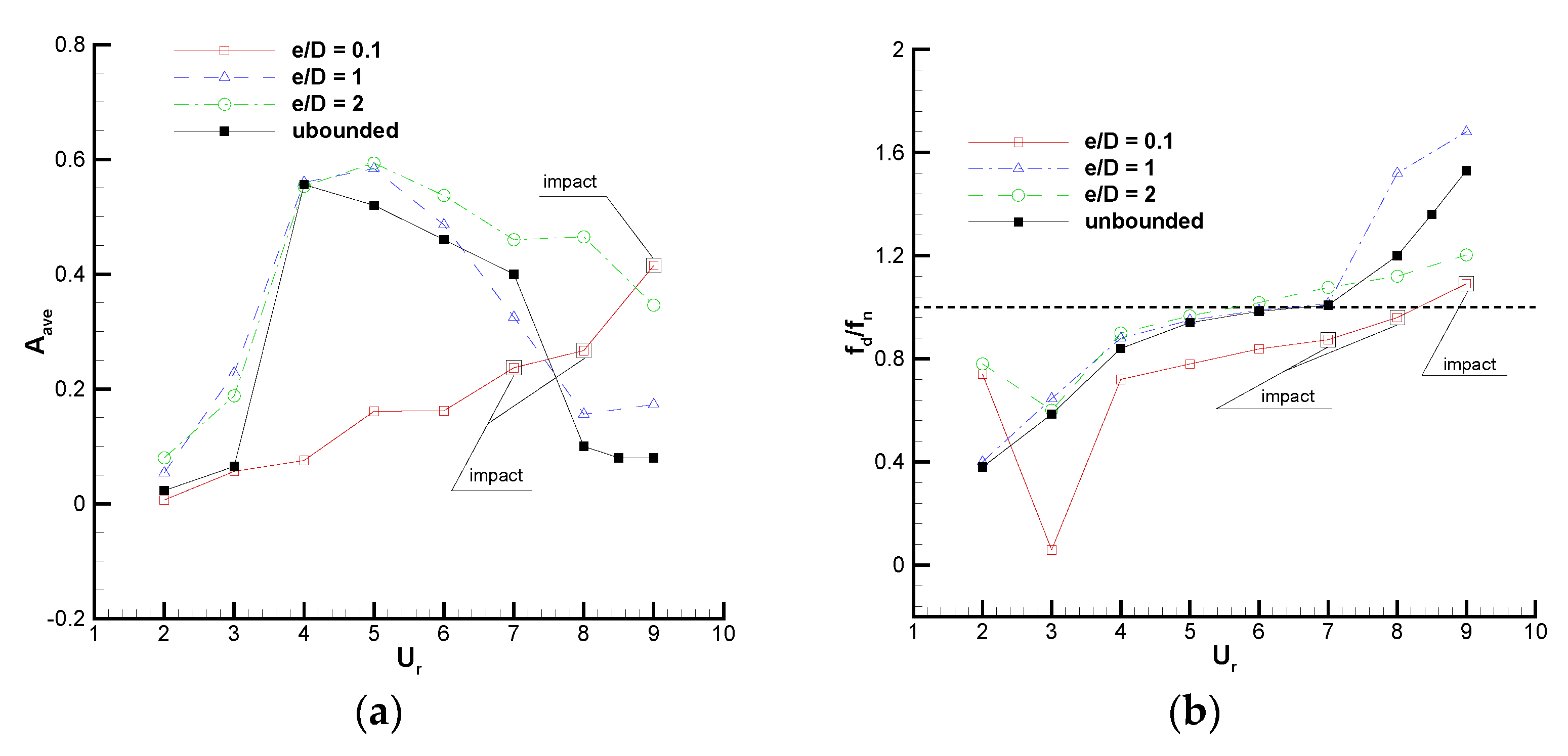
The variation of the non-dimensional amplitude and the predominant frequency of cylinder vibration with is presented in Figure 7, together with the results of the cylinder VIV in unbounded flows. In Figure 7a, it can be seen that the response amplitude in the case of is severely affected by the plane wall and it increases with . The cylinder-wall impact occurs at , which is marked in the figure. In the cases of and 2, the general trends of are similar to that in the unbounded flow and the response curves tend to have “initial”, “upper”, and “lower” branches. This is apparently due to the weaker effect of the wall. However, the maximum amplitudes of for and 2 are predicted at ; they are larger than that for the unbounded case predicted at . When , for and 2 are very close and the deviations become obvious when . It is interesting to find that when , the trend of for is much more similar to that in the unbounded case, even though the plane wall is farther away in the case of . A similar phenomenon is found for (Figure 7b) as the lock-in region for and the unbounded case is while that for is broadened, which results in a large amplitude at . Chung [38] reported that the size of the lock-in region increases with a decreasing gap ratio. This difference between the present study and the previous work of Chung would originate from the different Reynolds numbers or wall kinematics, which play important roles in determining the vibration amplitude [39].
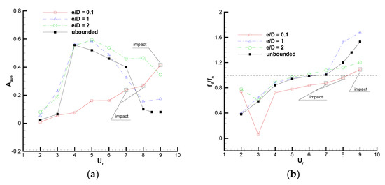
Figure 7.
Variation of and with for three gap ratios . (a) , (b) .
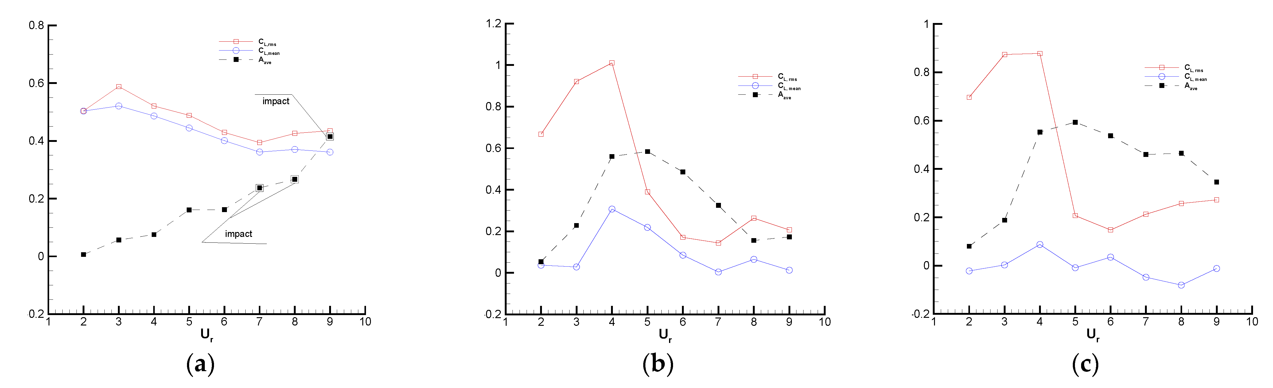
In order to understand how the hydrodynamic forcing causes the above amplitude response, Figure 8 presents two different statistics of the lift coefficients versus , including the root-mean-square value of the lift coefficient and the time-averaged value of the lift coefficient . To conveniently find the relationship between the amplitude response and the hydrodynamics, is also plotted in the figures. It can be seen that the peaks of for all three differ from the points where the maximal values of occur. Impact with the wall in the case of causes the trend of to be changed. So, it can be guessed that must approach the maximal value where the impact has the potential to occur. The curves for show that the small-gap-ratio case acquires a higher than the large-gap-ratio one in the entire range of computed . For , decreases with the increasing , almost in the entire computed range, except for the reduced velocities where impact occurs. The above regularities found for are consistent with those by Chung [38]. However, for a larger ( or 2), the overall trend of is that it increases in the range of and decreases beyond .
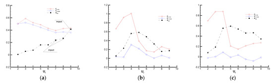
Figure 8.
Variation of and with for three gaps together with a variation of . (a) ; (b) ; (c) .
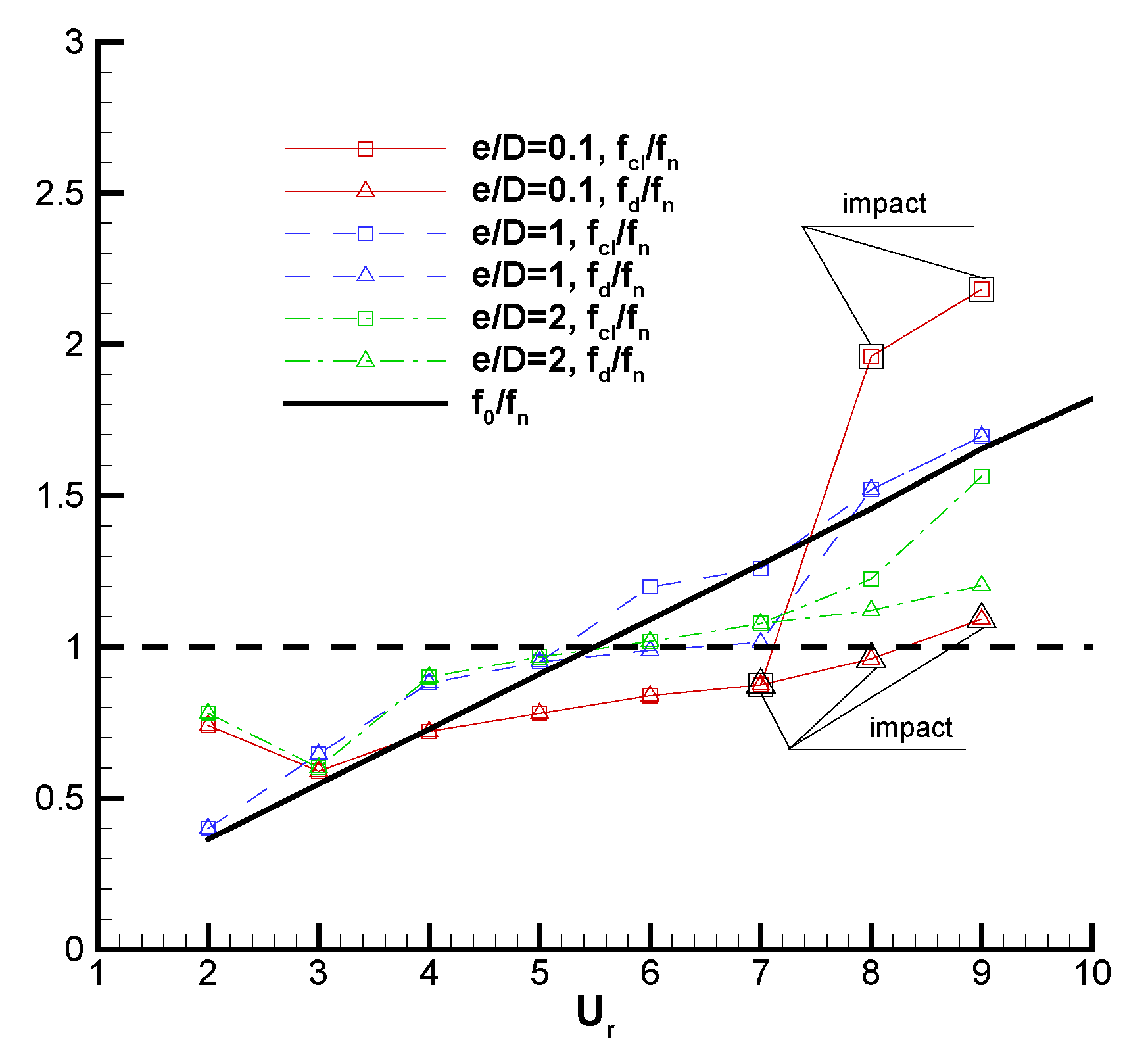
The vibration frequency is also a major concern with regard to structure fatigue and noise generation. So, it is worth it to explore the relation between the frequency of hydrodynamic force and cylinder vibration. Figure 9 shows the variation in the predominant frequency of cylinder vibration and hydrodynamic force with for three gap ratios, in comparison with the straight line representing the Strouhal frequency of an isolated stationary circular cylinder at , . For , in the range of . However, deviates from at and 9. A similar deviation can be seen in the work of Chung [38] for the large-gap-ratio case. In addition, it is predicted that in the low- part and in the high- part. For , exceeds in the whole range of and deviates from at and 7, i.e., the high- part in the lock-in region. For , and are the same as before while is considerably larger than and at and 9, where approaches . The case in [40] with and , which is analogous to the present case with and , also shows that is considerably larger than in the lock-in region. This may be due to the impact between the cylinder and the plane wall.
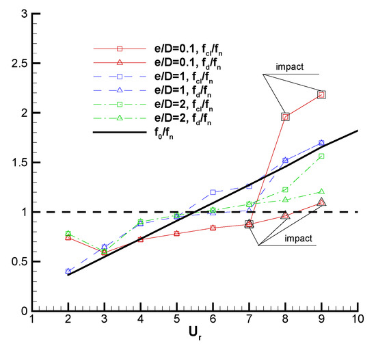
Figure 9.
Variation of and with for three gap ratios .
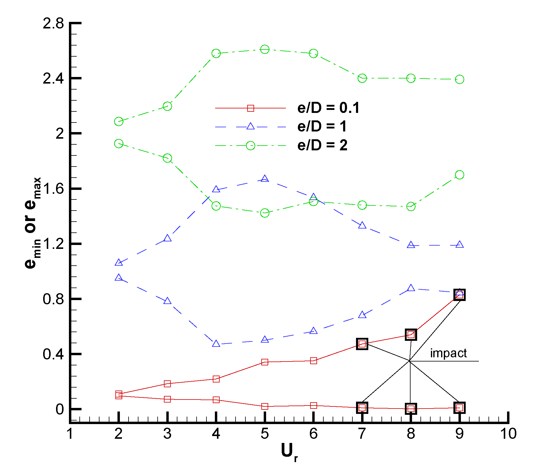
The minimal and maximal gaps, and , encountered through the course of cylinder vibration for three are presented in Figure 10. It is observed that the vibrating cylinder can move to positions very close to the plane wall in nearly the whole range of and increases with the increasing of the current considered range in the case of . Two conclusions can be obtained from the figure. One is that and increase with an increasing gap ratio. This is easy to explain as the effects of the wall on the cylinder are decreased with larger gap ratios. The second is that a larger always accompanies a smaller in the lock-in region for all the three cases with a different .
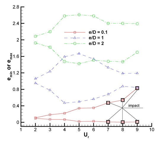
Figure 10.
Variation of the minimal and maximal gaps for three .
For quite a long time, the vortex structures in the wake behind a bluff body have attracted the attention of researchers. Deep insight into the physics involved would be very useful for engineering applications. So, the vortex shedding patterns of the near-wall cylinder at different gap ratios are presented to illustrate the influence of the wall proximity under various reduced velocities.
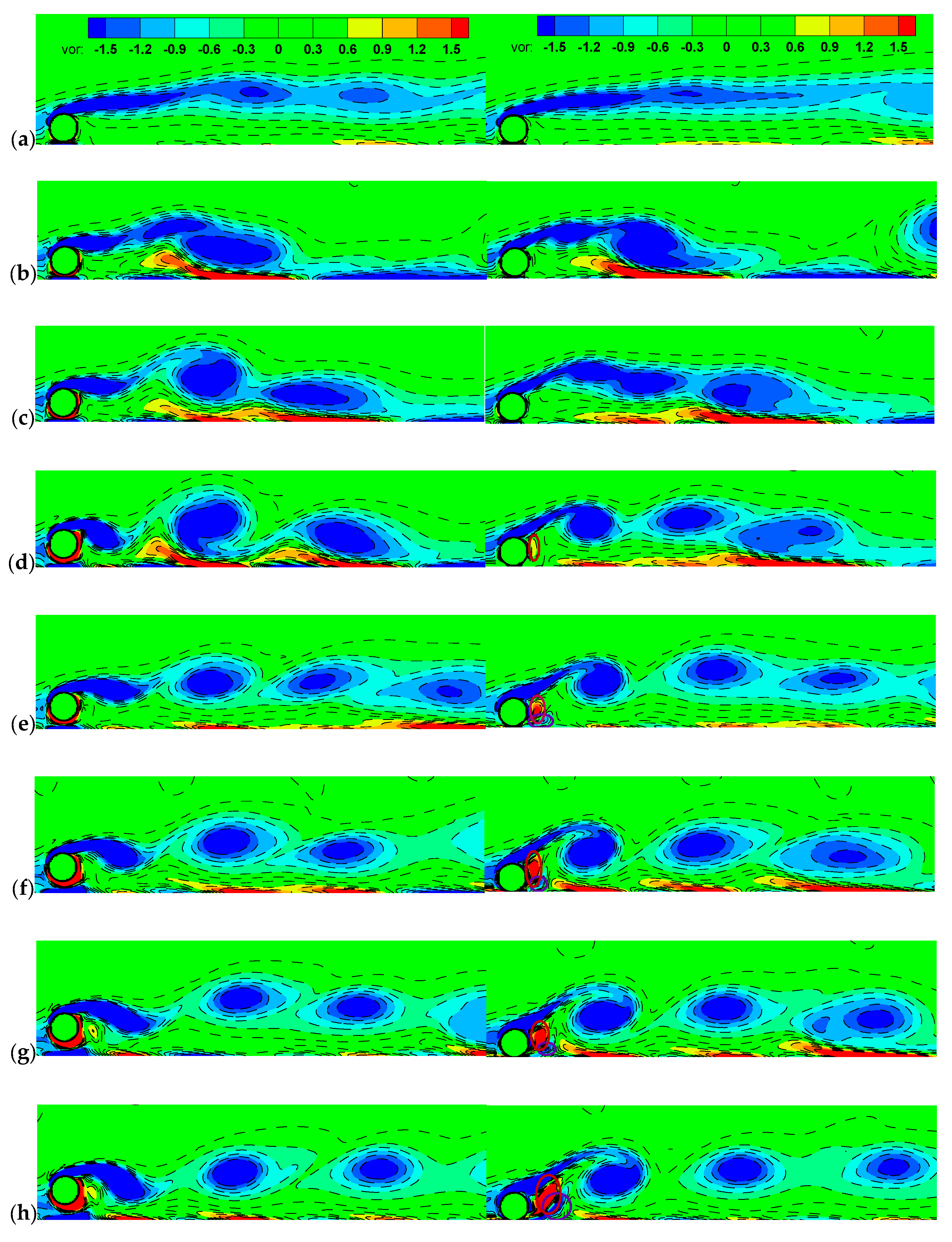
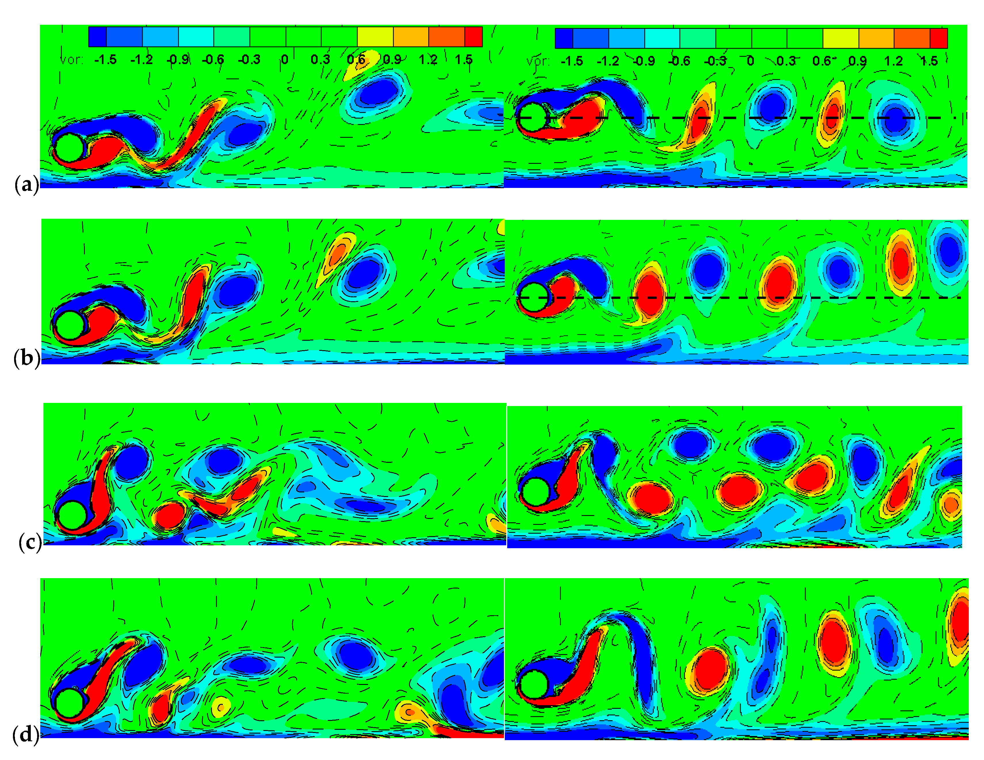
Figure 11 shows instantaneous vorticity contours for at when the cylinder is at the highest (left) and lowest (right) positions during the vibration cycle. Overall, the vortices shed from the gap-side surface of the cylinder are suppressed due to the interaction with negative vortices generated on the plane wall. With increasing , the induced separation zone of the plane boundary layer is getting larger. At , the vibration of the negative vortices shed from the freestream-side surface is not obvious due to the extremely small . Even though the minimum gap and the cylinder amplitude are very close at and 4, the vortex shedding patterns are different in that there exists periodic shedding of the positive vortices behind the cylinder at . An obviously periodic shedding of the negative vortices from the freestream-side surface of the cylinder is shown at , 7, 8, and 9. Furthermore, it can be seen clearly from the lowest-position contours (right column in Figure 11) that the strength of the positive vortex immediately behind the cylinder is stronger with increasing and even a negative vortex is induced to be shed from the plane wall at , 7, 8, and 9 (marked with circles in Figure 11 d–h). By comparing with the vorticity contours at the highest and lowest positions, one apparent finding is that the vortex formation length, which is defined as the streamwise distance from the cylinder center to the core of the fully formed vortex [41], at the highest position, is shorter than that at the lowest position.
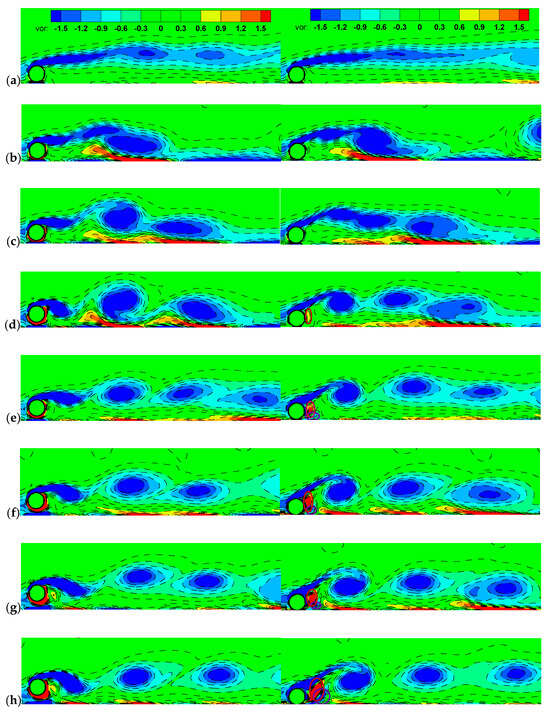
Figure 11.
Instantaneous vorticity contours for . (a–h): 2, 3, 4, 5, 6, 7, 8, 9. “vor” in the figure represents vorticity.
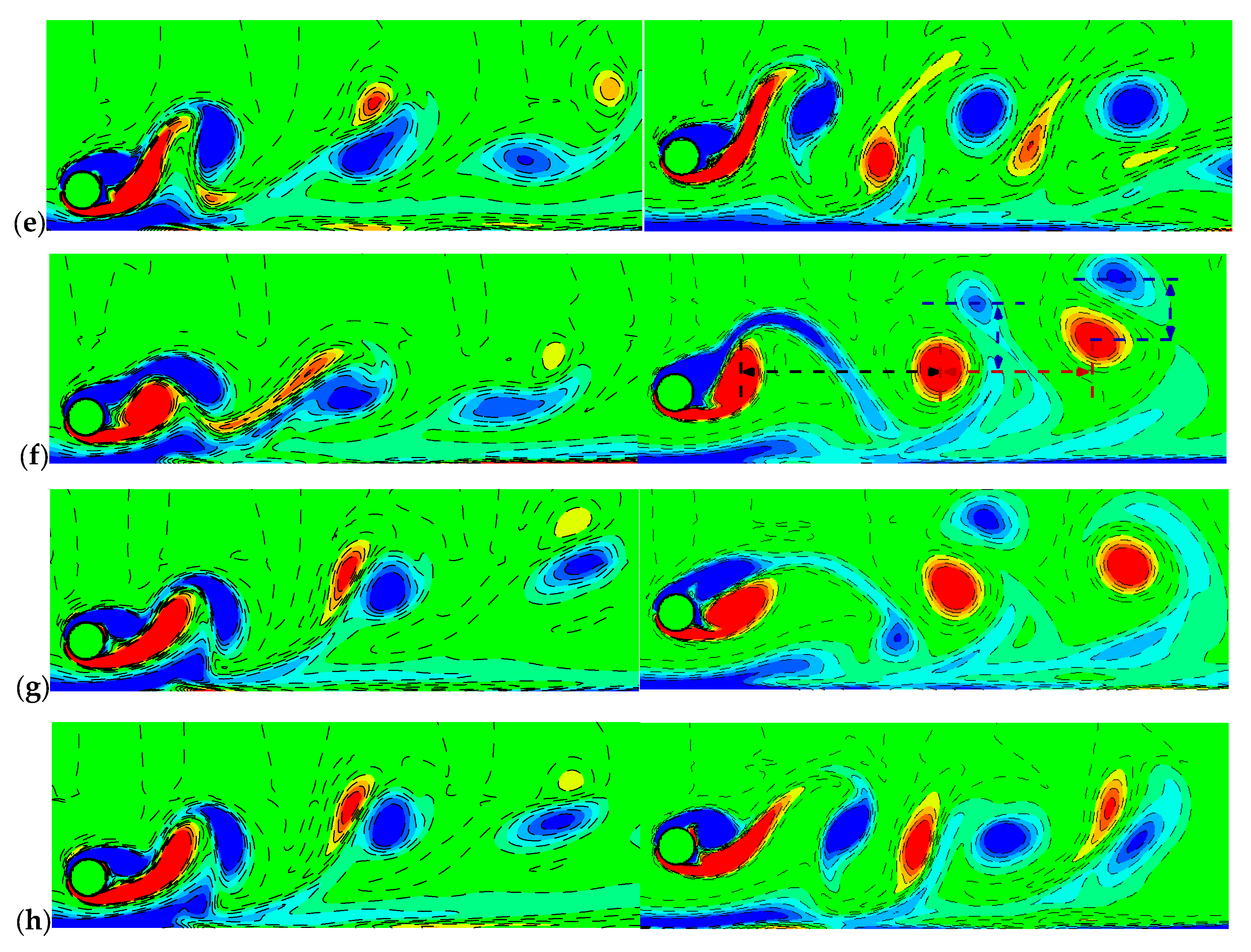
Figure 12 plots instantaneous vorticity contours for and when the cylinder is at the lowest position during the vibration cycle. The vortex shedding pattern for is very different from that for . For (left column in Figure 12), the negative vortex accompanied by a positive vortex can be seen at each , even though the strength of the positive one is much weaker. The strength of the interaction between the cylinder and the plane wall changes with the cylinder amplitude. An obvious separation of the plane boundary layer can be seen in the lock-in region when the amplitude value is relatively large. However, a slighter separation in the boundary layer is seen at the other reduced velocities.
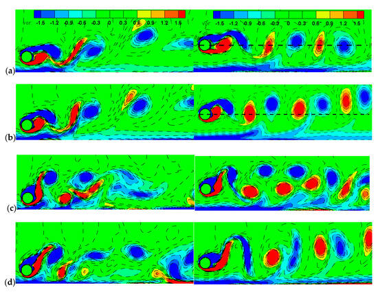
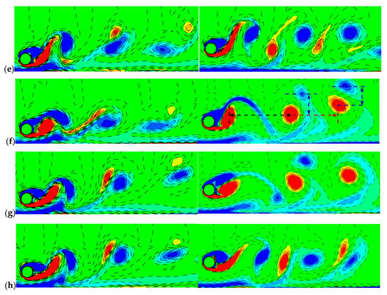
Figure 12.
Instantaneous vorticity contours for . (left) and . (right). (a–h): 2, 3, 4, 5, 6, 7, 8, 9. “vor” in the figure represents vorticity.
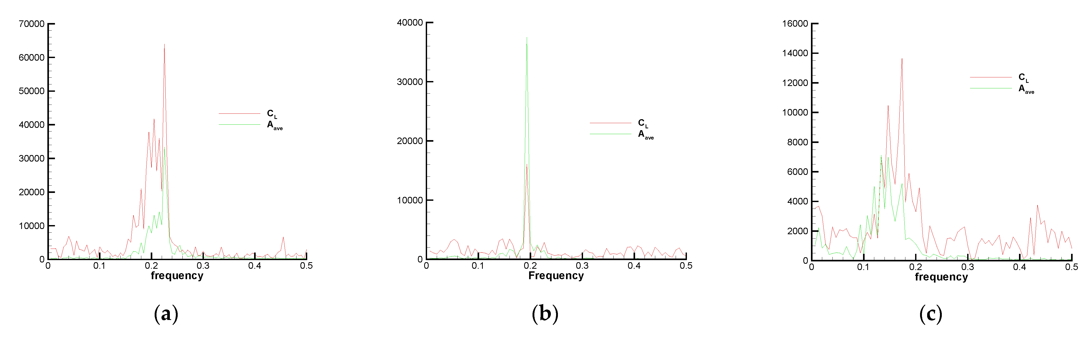
Govardhan and Williamson [8] showed that the initial and upper branches are associated with 2S and 2P vortex modes in the unbounded case. As shown in Figure 12 (right column), for the case of , the positive vortices become stronger and the vortex patterns are arranged in 2S at and , i.e., two opposite-sign vortices per shedding cycle. Due to the small and large , the shedding vortices are substantially symmetric to the cylinder centerline at while asymmetry is caused by the plane wall at . At , the transverse spacing between the opposite-signed and negative-signed vortices becomes obviously larger, causing the shedding vortices in the wake near the cylinder to be arranged in 2P mode. But it tends to be in 2S mode away from the cylinder. Despite the amplitude, the minimal and maximal gaps at are very close to that at , the vortex pattern seems to be in 2S at . At and , the negative-signed vortices are weaker than the positive ones and the vortex shedding mode is very different from the traditional vortex street in that the transverse spacing is larger and the streamwise spacing is smaller, as marked in Figure 12f. At , the mode tends to be in 2S near the cylinder. However, the transverse spacing is larger and the streamwise spacing is smaller away from the cylinder. In Figure 13, the Fast Fourier Transform (FFT) of the lift coefficient and displacement to the physical time at , , and is given. It can be concluded from the FFT of that the vortices shed in different modes near and away from the cylinder are always with different frequencies.
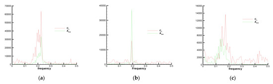
Figure 13.
FFT of lift coefficient and displacement to the physical time for . (a); (b) ; (c) .
4.2. VIV of Two Inline Cylinders Close to a Plane Wall
In this subsection, the VIV of two inline cylinders close to a plane wall is investigated. The parameters, like , , , , and , are all set to be the same as those in Section 4.1 for comparison. The center-to-center spacing of the two cylinders is , which is categorized into the reattachment region by Zdravkovich [19].
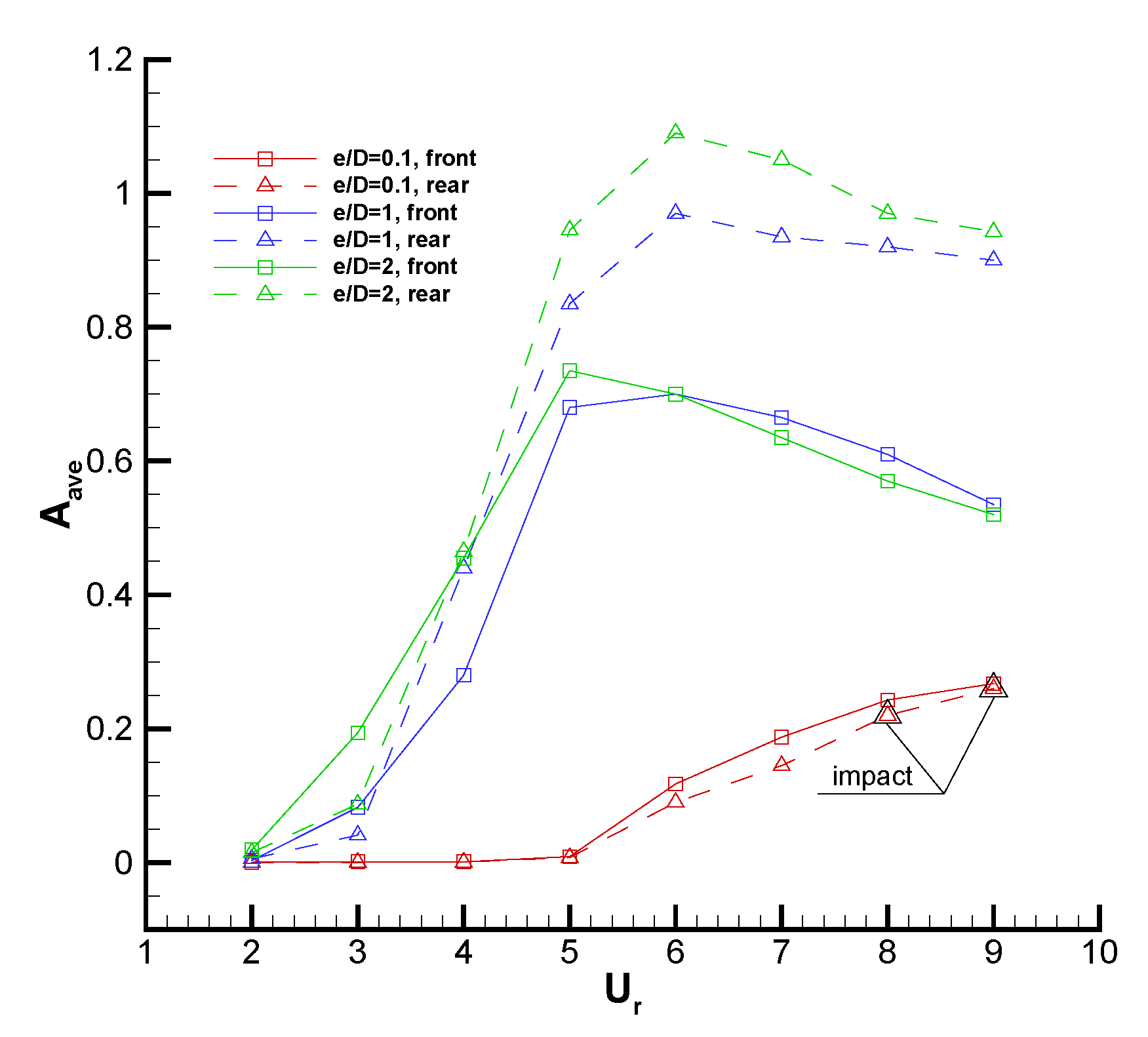
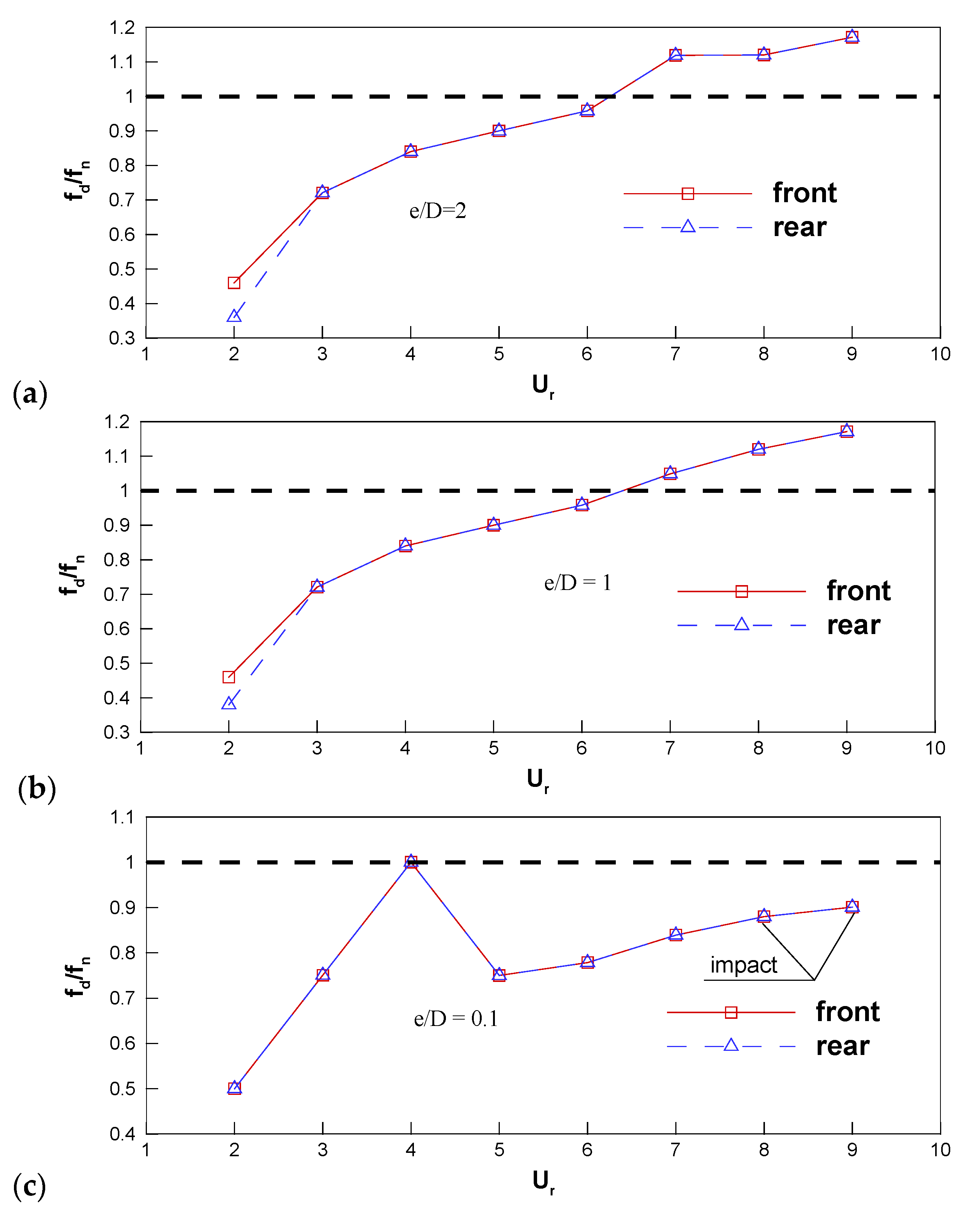
Figure 14 and Figure 15 show the variation of the non-dimensional amplitudes and the predominant frequency of the cylinder vibration with for different and the two inline cylinders are denoted by ‘front’ and ‘rear’, respectively. For , the for the two cylinders is almost zero and increases linearly when . For , the of the two cylinders increases with and the amplitude of the front cylinder is larger than that of the rear one. However, collision with the wall occurs only for the rear cylinder. Additionally, for the two cylinders is the same for all . The predicted trend of the cylinder amplitude in the present work is very close to that in the study of Chen et al. [21] for two inline cylinders with and . Due to the larger and weaker interaction between the boundary layer of the cylinder and the plane wall in the work of Chen et al., the amplitude of the rear cylinder is larger than that of the front one. Compared to the case of an isolated cylinder near a plane wall, the increasing trend of is suppressed and it can be seen from the variation of that the lock-in region is non- existent for . For and 2, significant vibrations of the two cylinders are excited, especially for the rear cylinder. The amplitude of the rear cylinder is larger than that of the front one when approaches unity, i.e., in the lock-in region. For the front cylinder, for is smaller than that for when while for becomes larger than that for when . For the rear cylinder, for is always smaller than that for . From current computations, it can be guessed that the amplitude for the rear cylinder increases with . Compared to the case of an isolated cylinder near a plane wall, the vibration amplitudes are larger and the lock-in region is obviously broadened.
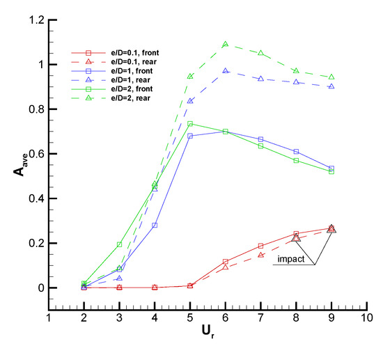
Figure 14.
Variation of with for three gap ratios .
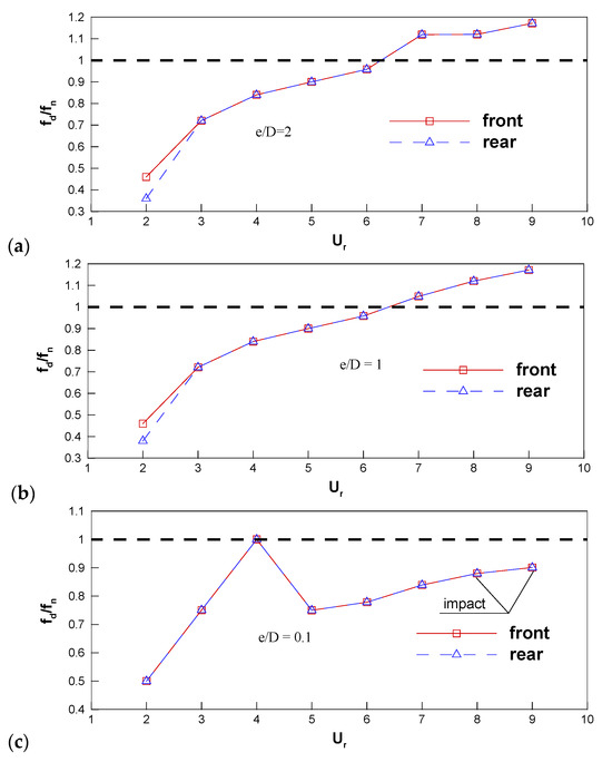
Figure 15.
Variation of with for three gap ratios . (a) = 2; (b) = 1; (c) = 0.1.
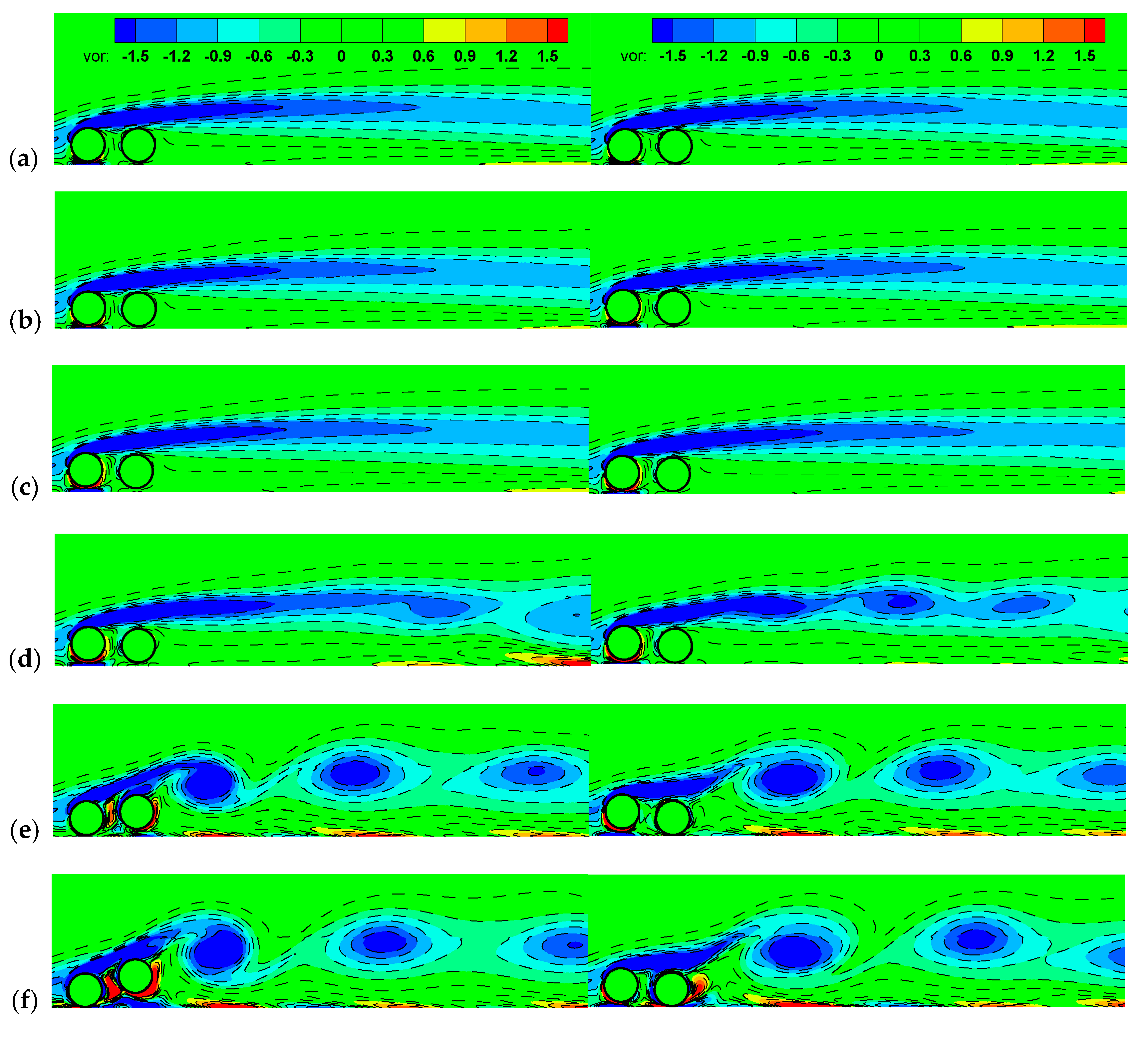
Figure 16 shows the vorticity contours in the wake at various values for when the displacement of the left cylinder center or right cylinder center nearly reaches a local minimum during the vibration cycle, corresponding to the left or right column in the figure, respectively. For when the amplitudes of the cylinders are almost zero, the shear layer of the front cylinder encloses the two cylinders and exhibits no fluctuations in the wake, leading to a stable state. The gap-side shear layer is suppressed by the near-wall effects, so only a single and elongated freestream-side vortex exists in the wake. At , the cylinders vibrate slightly and the elongated freestream-side shear layer is broken and the boundary layer of the plane wall is induced to be separated. As increases and the cylinders vibrate obviously, periodically shedding negative and positive vortices can be seen in the wake, even though the intensities of the positive ones are lower than the negative ones due to the suppression of the plane boundary layer (Figure 16e,f).
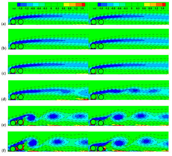
Figure 16.
Instantaneous vorticity contours for . (a–d): 2, 3, 4, 5; (e) 7; (f) 9. “vor” in the figure represents vorticity.
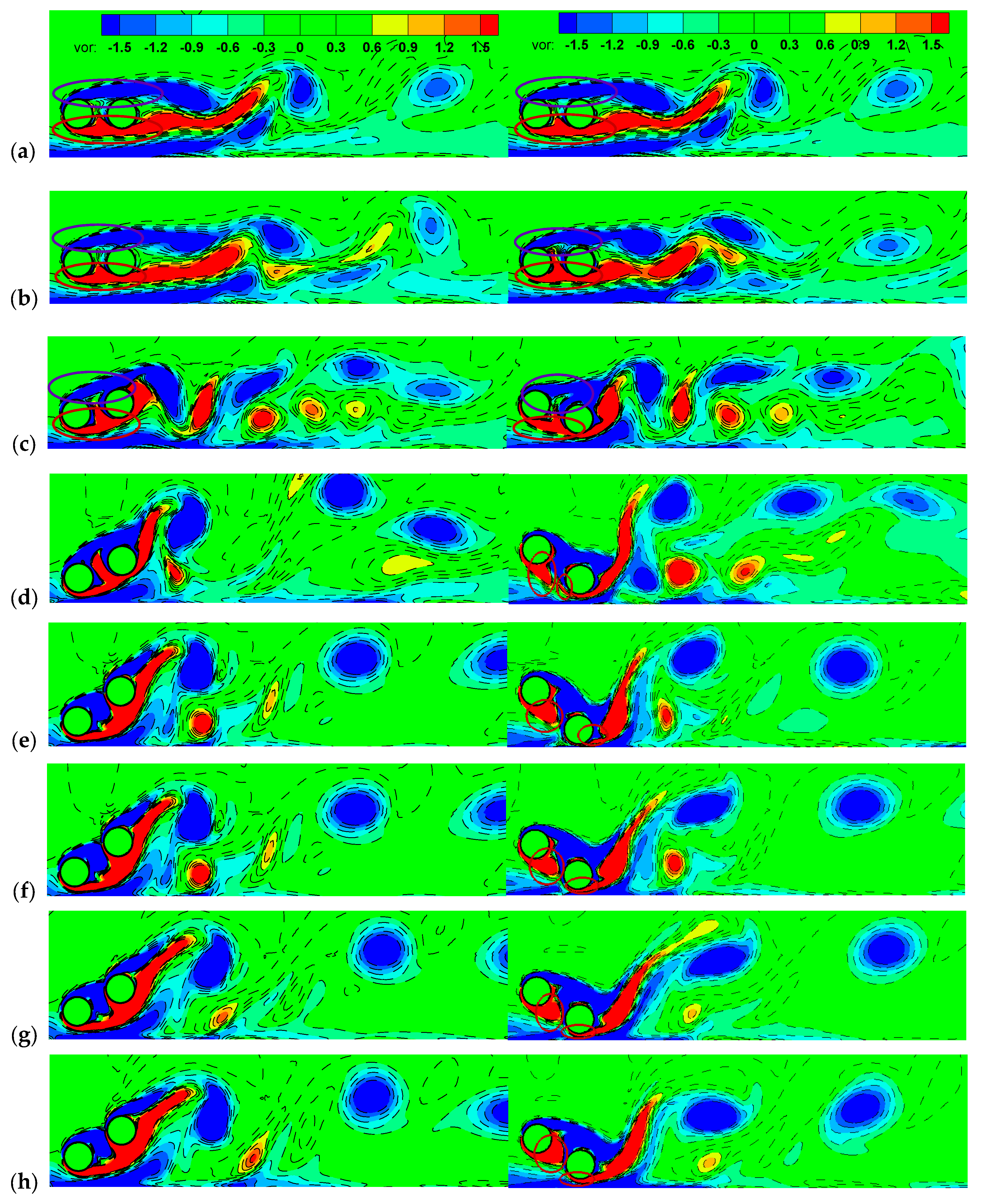
Figure 17 shows the vorticity contours for when the displacement of the left cylinder center or right cylinder center nearly reaches a local minimum during the vibration cycle, corresponding to the left or right column in the figure, respectively. It can be seen that the vortices freely shed from both sides of the rear cylinder. Due to the suppression of the plane boundary layer, the gap-side vortices quickly dampen out in the wake. When the amplitude of the rear cylinder becomes large, the vortex shedding pattern tends to be 2P (Figure 17c–h) near the rear cylinder. From the right column, the shear layer of the front cylinder encircles the rear cylinder at (marked by the circle in Figure 17a–c) while the gap-side shear layer impinges on the rear cylinder and splits into two parts at (marked by the circle in Figure 17d–h). This is due to the small gap between the rear cylinder and the plane wall in the lock-in region, which leads to strong interaction between the gap-side shear layer and the plane boundary layer.
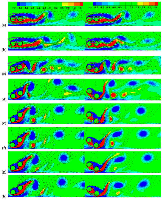
Figure 17.
Instantaneous vorticity contours for . (a–h): 2, 3, 4, 5, 6, 7, 8, 9. “vor” in the figure represents vorticity.
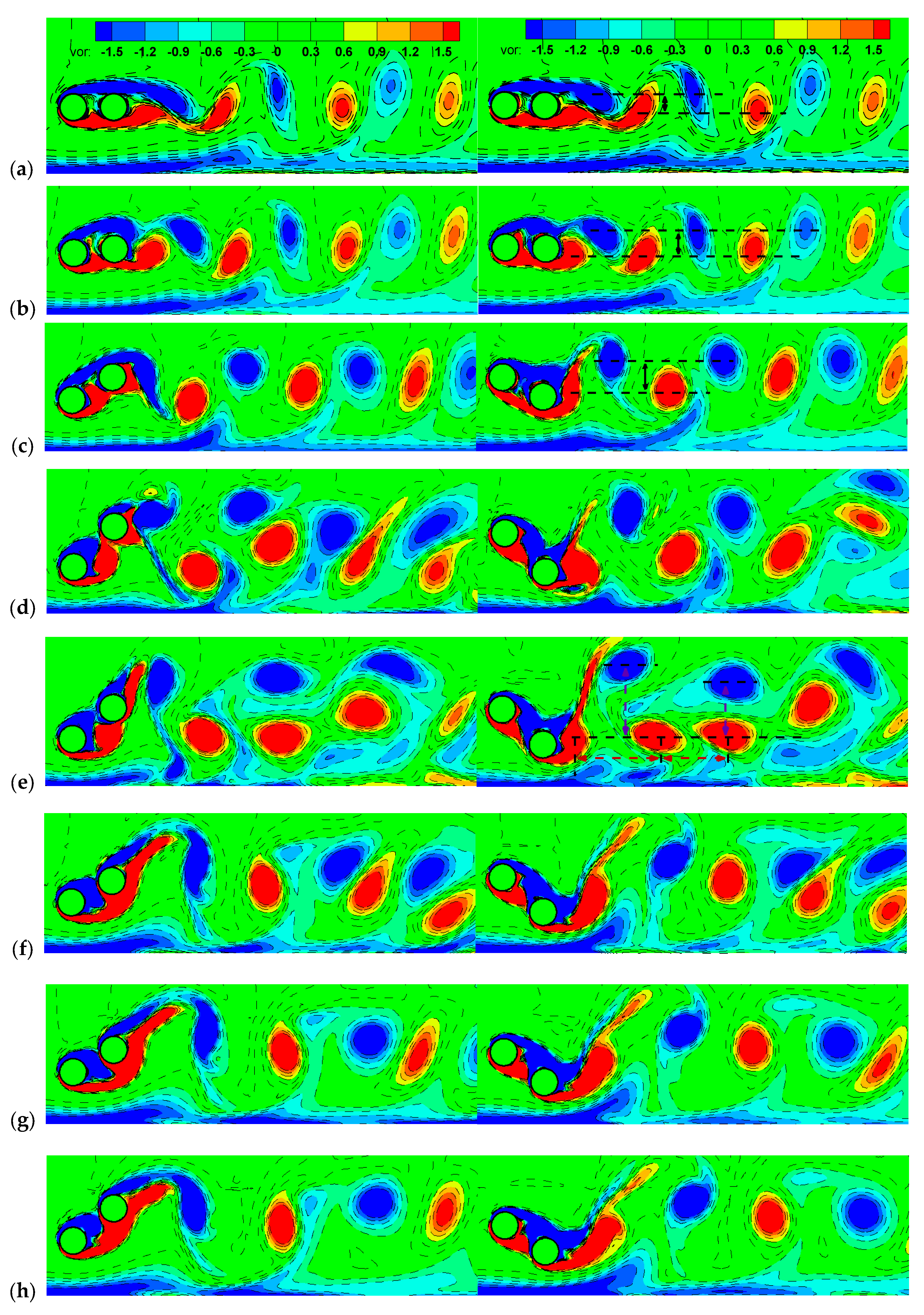
Figure 18 shows the vorticity contours for . Each snapshot is taken at the instant when the displacement of the front cylinder center (left column) or rear cylinder center (right column) nearly reaches a local minimum. Compared to the results for , the positive vortices shed from the gap-side shear layer become stronger. At and 6, the pattern seems to be 2P near the cylinder and the streamwise and transverse spacing gets smaller away from the cylinder, as illustrated in Figure 18e. This may be due to the shedding of negative vortices from the plane boundary layer. For , the shedding vortex is similar and is in 2S mode. The difference lies in that the transverse spacing between the positive and negative vortices becomes larger with increasing . For , the vortex shedding mode is also in 2S and we can see that the streamwise spacing between the positive and negative vortices is smaller away from the cylinder. Similar to the results for , the gap-side or freestream-side shear layer impinges on the rear cylinder and splits into two parts at .
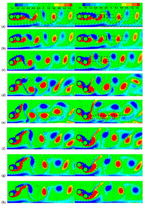
Figure 18.
Instantaneous vorticity contours for . (a–h): 2, 3, 4, 5, 6, 7, 8, 9. “vor” in the figure represents vorticity.
5. Conclusions and Summary
Numerical studies on vortex-induced transverse vibration of an isolated cylinder and two tandemly arranged cylinders near a plane wall with , , , , , and have been conducted. The self-developed DFD method is adopted to avoid the application of a remeshing technique when the gap between the cylinder and the wall is very small. In addition, a bounce-back model is adopted when the cylinder collides with the wall. The research has important significance for the design of near-wall cylindrical structures in engineering practices. The main conclusions of this study are summarized as follows:
(1) For the one-isolated-cylinder case, collision with the wall occurs at a larger reduced velocity and a higher time-averaged lift coefficient is acquired for a small . For each of the three , the predominant frequency of cylinder vibration coincides with that of the hydrodynamic force at the most and deviation occurs at large . The minimal and maximal gaps, and , increase with increasing and a larger always accompanies a smaller in the lock-in region. The positive vortices shed from the gap-side surface are suppressed and their intensity gradually becomes stronger as increases;
(2) For the two-inline-cylinders case, the response amplitude of the front cylinder is larger than that of the rear one when is small. As increases, significant vibrations are excited, especially for the rear cylinder, leading to the amplitude of the rear cylinder being larger than that of the front one when approach unity. The amplitude of the rear cylinder increases with . For a small , the vortices shed from the gap-side surface are also suppressed by the plane wall and only a single and elongated freestream-side vortex exists at small . However, 2P mode can be seen at the lock-in region when increases, even though the gap-side vortices damped out away from the cylinder;
(3) Compared to the one-isolated-cylinder case, the vibrations of the cylinders are suppressed and the collision with the wall only occurs for the rear cylinder when is small. In addition, the vibration amplitudes of the front and rear cylinders are both larger and the lock-in region is obviously broadened.
In this paper, the VIV of rigid cylinders near a plane wall is investigated and the above conclusions are obtained without considering the cylinders’ deformation, which will be considered in our future work. Additionally, the Reynolds number in all the computational cases is 150, which is in the 2D laminar flow region, and the future extension is towards three-dimensional high-Reynolds-number flow simulations.
Author Contributions
Conceptualization, H.Q.; methodology, T.P. and Y.Z.; software, T.P. and C.Z.; validation, Y.Z. and H.J.; formal analysis, T.P.; investigation, T.P. and H.J.; resources, T.P. and W.Z.; data curation, T.P. and Z.S.; writing—original draft preparation, H.Q. and T.P.; writing—review and editing, H.Q. and Z.S.; visualization, Z.S. and H.J.; supervision, H.Q.; project administration, H.Q.; funding acquisition, H.Q. and T.P. All authors have read and agreed to the published version of the manuscript.
Funding
This research was funded by the National Natural Science Foundation of China (No. 12102154), the Foundation of State Key Laboratory of Aerodynamics of China Aerodynamics Research and Development Center (No.RAL202302-1), and the Nature Science Foundation of Yangzhou (No. YZ2024164).
Institutional Review Board Statement
Not applicable.
Informed Consent Statement
Not applicable.
Data Availability Statement
Data is contained within the article.
Conflicts of Interest
The authors declare no conflicts of interest.
References
- Boersma, P.R.; Rothstein, J.P.; Modarres-Sadeghi, Y. Experimental investigation of vortex-induced vibrations of a flexibly mounted cylinder in a shear-thinning fluid. Phys. Rev. Fluids 2023, 8, 044703. [Google Scholar] [CrossRef]
- Zhu, H.; Xu, H.; Liu, B.; Zhong, J. Numerical investigation of the vortex-induced vibration of a circular cylinder in oscillatory flow. Ocean. Eng. 2024, 310, 118666. [Google Scholar] [CrossRef]
- Williamson, C.H.K.; Govardhan, R. Vortex-Induced Vibrations. Annu. Rev. Fluid Mech. 2004, 36, 413–455. [Google Scholar] [CrossRef]
- Kim, S.; Alam, M.M.; Sakamoto, H.; Zhou, Y. Flow-induced vibrations of two circular cylinders in tandem arrangement. Part 1: Characteristics of vibration. J. Wind. Eng. Ind. Aerodyn. 2009, 97, 304–311. [Google Scholar] [CrossRef]
- Bearman, P.W. Circular cylinder wakes and vortex-induced vibrations. J. Fluids Struct. 2011, 27, 648–658. [Google Scholar] [CrossRef]
- Yang, Z.-M.; Ding, L.; Ye, Q.-Y.; Yang, L.; Zhang, L. Effect of Gap Flow on the Characteristics of Flow-Around and Flow-Induced Vibration for Two Circular Cylinders with Roughness Strips. Appl. Sci. 2019, 9, 3587. [Google Scholar] [CrossRef]
- Khalak, A.; Williamson, C.H.K. Motions, forces and mode transitions in vortex-induced vibrations at low mass-damping. J. Fluids Struct. 1999, 13, 813–851. [Google Scholar] [CrossRef]
- Govardhan, R.; Williamson, C.H.K. Modes of vortex formation and frequency response of a freely vibrating cylinder. J. Fluid Mech. 2000, 420, 85–130. [Google Scholar] [CrossRef]
- Jauvtis, N.; Williamson, C.H.K. The effect of two degrees of freedom on vortex-induced vibration at low mass and damping. J. Fluid Mech. 2004, 509, 23–62. [Google Scholar] [CrossRef]
- Khalil, M.; Ruggieri, S.; Tateo, V.; Nascimbene, R.; Uva, G. A numerical procedure to estimate seismic fragility of cylindrical ground-supported steel silos containing granular-like material. Bull. Earthq. Eng. 2023, 21, 5915–5947. [Google Scholar] [CrossRef]
- Rotter, J.M. Elephant’s foot buckling in pressurised cylindrical shells. Stahlbau 2006, 75, 742–747. [Google Scholar] [CrossRef]
- Mehretehran, A.M.; Maleki, S. Seismic response and failure modes of steel silos with isotropic stepped walls: The effect of vertical component of ground motion and comparison of buckling resistances under seismic actions with those under wind or discharge loads. Eng. Fail. Anal. 2021, 120, 105100. [Google Scholar] [CrossRef]
- Virella, J.C.; Suárez, L.E.; Godoy, L.A. A Static Nonlinear Procedure for the Evaluation of the Elastic Buckling of Anchored Steel Tanks Due to Earthquakes. J. Earthq. Eng. 2008, 12, 999–1022. [Google Scholar] [CrossRef]
- Tham, D.M.Y.; Gurugubelli, P.S.; Li, Z.; Jaiman, R.K. Freely vibrating circular cylinder in the vicinity of a stationary wall. J. Fluids Struct. 2015, 59, 103–128. [Google Scholar] [CrossRef]
- Chen, L.F.; Wu, G.X. Flow-induced transverse vibration of a circular cylinder close to a plane wall at small gap ratios. Appl. Ocean. Res. 2020, 103, 102344. [Google Scholar] [CrossRef]
- De, A.K.; Sarkar, S. Vortex shedding modes of a vibrating cylinder colliding with a rigid wall. Phys. Fluids 2022, 34, 071702. [Google Scholar] [CrossRef]
- Gao, Y.; Liu, L.; Zou, L.; Zhang, Z.; Yang, B. Effect of surface roughness on vortex-induced vibrations of a freely vibrating cylinder near a stationary plane wall. Ocean. Eng. 2020, 198, 106837. [Google Scholar] [CrossRef]
- Wang, C.; Hua, X.; Huang, Z.; Wen, Q. Aerodynamic Characteristics of Coupled Twin Circular Bridge Hangers with Near Wake Interference. Appl. Sci. 2021, 11, 4189. [Google Scholar] [CrossRef]
- Zdravkovich, M.M. The effects of interference between circular cylinders in cross flow. J. Fluids Struct. 1987, 1, 239–261. [Google Scholar] [CrossRef]
- Mahbub Alam, M.; Moriya, M.; Sakamoto, H. Aerodynamic characteristics of two side-by-side circular cylinders and application of wavelet analysis on the switching phenomenon. J. Fluids Struct. 2003, 18, 325–346. [Google Scholar] [CrossRef]
- Chen, W.; Ji, C.; Xu, D.; Zhang, Z. Vortex-induced vibrations of two inline circular cylinders in proximity to a stationary wall. J. Fluids Struct. 2020, 94, 102958. [Google Scholar] [CrossRef]
- Zhou, C.; Shu, C.; Wu, Y. Extension of domain-free discretization method to simulate compressible flows over fixed and moving bodies. Int. J. Numer. Methods Fluids 2007, 53, 175–199. [Google Scholar] [CrossRef]
- Zhou, C.H.; Shu, C. A local domain-free discretization method for simulation of incompressible flows over moving bodies. Int. J. Numer. Methods Fluids 2011, 66, 162–182. [Google Scholar] [CrossRef]
- Pu, T.; Zhou, C.; Ai, J. Extension of the local domain-free discretization method to large eddy simulation of turbulent flows. Int. J. Numer. Methods Fluids 2019, 90, 456–478. [Google Scholar] [CrossRef]
- Peskin, C.S. Flow patterns around heart valves: A numerical method. J. Comput. Phys. 1972, 10, 252–271. [Google Scholar] [CrossRef]
- Mavriplis, D.J.; Jameson, A. Multigrid solution of the Navier-Stokes equations on triangular meshes. AIAA J. 1990, 28, 1415–1425. [Google Scholar] [CrossRef]
- Belov, A.; Martinelli, L.; Jameson, A.; Belov, A.; Martinelli, L.; Jameson, A. Three-dimensional unsteady incompressible flow computations using multigrid. In Proceedings of the 35th Aerospace Sciences Meeting and Exhibit, Reno, NV, USA, 6–9 January 1997. [Google Scholar]
- Gilmanov, A.; Sotiropoulos, F.; Balaras, E. A general reconstruction algorithm for simulating flows with complex 3D immersed boundaries on Cartesian grids. J. Comput. Phys. 2003, 191, 660–669. [Google Scholar] [CrossRef]
- Angelidis, D.; Chawdhary, S.; Sotiropoulos, F. Unstructured Cartesian refinement with sharp interface immersed boundary method for 3D unsteady incompressible flows. J. Comput. Phys. 2016, 325, 272–300. [Google Scholar] [CrossRef]
- Bose, S.T.; Moin, P.; You, D. Grid-independent large-eddy simulation using explicit filtering. Phys. Fluids 2010, 22, 85774. [Google Scholar] [CrossRef]
- Schulz, K.W.; Kallinderis, Y. Unsteady Flow Structure Interaction for Incompressible Flows Using Deformable Hybrid Grids. J. Comput. Phys. 1998, 143, 569–597. [Google Scholar] [CrossRef]
- Borazjani, I.; Ge, L.; Sotiropoulos, F. Curvilinear immersed boundary method for simulating fluid structure interaction with complex 3D rigid bodies. J. Comput. Phys. 2008, 227, 7587–7620. [Google Scholar] [CrossRef] [PubMed]
- Zhao, M.; Cheng, L. Numerical simulation of two-degree-of-freedom vortex-induced vibration of a circular cylinder close to a plane boundary. J. Fluids Struct. 2011, 27, 1097–1110. [Google Scholar] [CrossRef]
- Bao, Y.; Zhou, D.; Tu, J. Flow interference between a stationary cylinder and an elastically mounted cylinder arranged in proximity. J. Fluids Struct. 2011, 27, 1425–1446. [Google Scholar] [CrossRef]
- Zhao, M.; Cheng, L.; An, H.; Lu, L. Three-dimensional numerical simulation of vortex-induced vibration of an elastically mounted rigid circular cylinder in steady current. J. Fluids Struct. 2014, 50, 292–311. [Google Scholar] [CrossRef]
- Ahn, H.T.; Kallinderis, Y. Strongly coupled flow/structure interactions with a geometrically conservative ALE scheme on general hybrid meshes. J. Comput. Phys. 2006, 219, 671–696. [Google Scholar] [CrossRef]
- Griffin, O.M. Vortex-Induced Vibrations of Marine Structures in Uniform and Sheared Currents; University of Michigan: Washington, DC, USA, 1992. [Google Scholar]
- Chung, M.-H. Transverse vortex-induced vibration of spring-supported circular cylinder translating near a plane wall. Eur. J. Mech. B Fluids 2016, 55, 88–103. [Google Scholar] [CrossRef]
- Raghavan, K.; Bernitsas, M.M.; Maroulis, D.E. Effect of bottom boundary on VIV for energy harnessing at 8 × 10³ < Re < 1.5 × 10⁵. J. Offshore Mech. Arct. Eng. 2009, 131, 79798. [Google Scholar] [CrossRef]
- Fredsoe, J.; Sumer, B.M.; Andersen, J.; Hansen, E.A. Transverse vibrations of a cylinder very close to a plane wall. J. Offshore Mech. Arct. Eng. 1987, 109, 52–60. [Google Scholar] [CrossRef]
- Krishnamoorthy, S.; Price, S.J.; PaÏDoussis, M.P. Cross-flow past an oscillating circular cylinder: Synchronization phenomena in the near wake. J. Fluids Struct. 2001, 15, 955–980. [Google Scholar] [CrossRef]


Disclaimer/Publisher’s Note: The statements, opinions and data contained in all publications are solely those of the individual author(s) and contributor(s) and not of MDPI and/or the editor(s). MDPI and/or the editor(s) disclaim responsibility for any injury to people or property resulting from any ideas, methods, instructions or products referred to in the content. |
© 2024 by the authors. Licensee MDPI, Basel, Switzerland. This article is an open access article distributed under the terms and conditions of the Creative Commons Attribution (CC BY) license (https://creativecommons.org/licenses/by/4.0/).