Article

Study on Vibration Damping Characteristics of Mounting Structure Based on the High Damping Alloy Material

1
School of Mechanical Engineering & Automation, Northeastern University, Shenyang 110819, China
2
Shenyang Engine Research Institute, Shenyang 110015, China
3
Shenyang Academy of Instrumentation Science Co., Ltd., Shenyang 110043, China
*
Author to whom correspondence should be addressed.
Appl. Sci. 2024, 14(23), 11056; https://doi.org/10.3390/app142311056
Submission received: 30 October 2024 / Revised: 20 November 2024 / Accepted: 25 November 2024 / Published: 27 November 2024

Abstract

:
The high damping alloy materials, by virtue of the excellent mechanical properties and damping performance generated by the material’s properties and internal friction mechanism, can be employed directly in the reduction of structural vibrations. On the basis of summarising the current research progress and application status of existing damping alloy materials, the damping characteristics of Fe-12Cr-3Al ferromagnetic high damping alloy material were tested and applied to the vibration reduction of an aero-engine lubricating oil tank. Subsequent to this, vibration characteristics simulation analysis and tests were conducted. The results show that the amplitude reduction rate of mounting structures utilising the Fe-12Cr-3Al ferromagnetic high damping alloy is 30% in comparison to Q235 carbon steel. Additionally, the vibration transmission rate can be diminished by 40%. The utilisation of the Fe-12Cr-3Al ferromagnetic high damping alloy in the aero-engine mounting structure has been observed to result in a discernible reduction in vibration.

1. Introduction

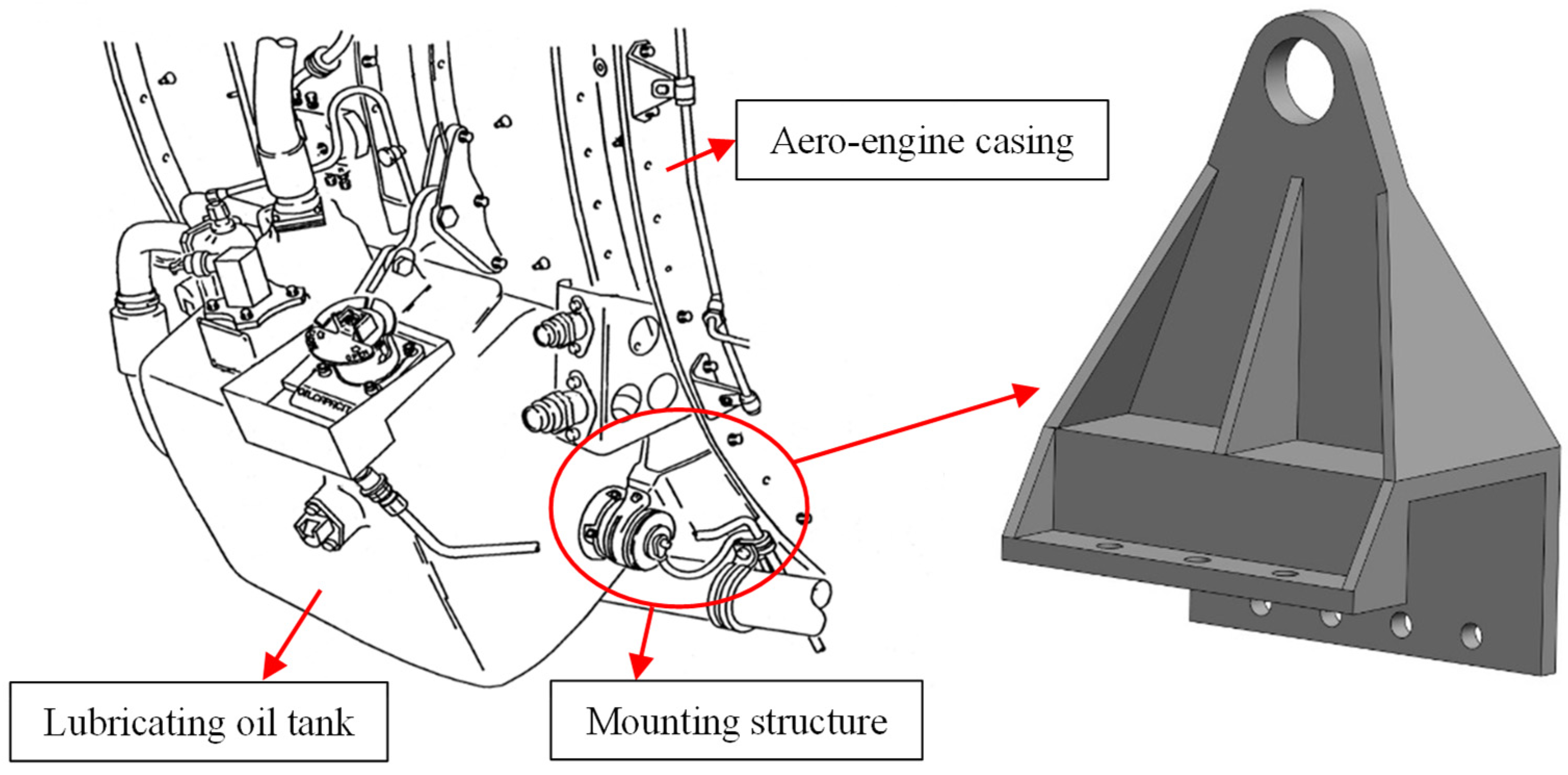
Lubrication systems in aero-engines are used to lubricate and cool bearings, gears, and splines to ensure a high level of safety and reliability for the aircraft even after long periods of operation [1]. One of the important components for storing the lubricating oil is the lubricating oil tank, which is fixed to the aero-engine casing by mounting structures. As shown in Figure 1, the installation arrangement of the lubricating oil tank on an AL-31FN aero-engine. Strong external vibrations of the aero-engine can cause vibration damage or faults in the lubricating oil tank and its mounting structure during services. Therefore, the reasonable vibration reduction of the lubricating oil tank is urgent. Traditional vibration reduction methods, such as adding damping devices, are often difficult to meet the requirements of equipment miniaturisation and lightweight [2]. On the contrary, the damping materials can be used to manufacture aero-engine components to reduce vibration at the source [3].
High damping alloys absorb external vibration energy through a variety of damping mechanisms within the material and convert it into thermal energy [4], thus generating internal dissipation to reduce the vibration and noise. High damping alloys are a novel class of functional structural materials that have been used in marine propellers, aircraft, machine tools, gears, fasteners, and other fields, and the application prospects are very promising [5,6]. High damping alloy materials can not only reduce the noise generated by machinery and its components but also absorb the damping energy [7], so that the vibration is extremely fast reduced, avoiding the fatigue damage caused by the intense vibration and prolonging the life of the machine parts. High damping alloy materials used for engineering applications should have as much as possible high damping, high strength, easy manufacturing, a large application range, low cost, and other comprehensive performance.
According to the generation mechanism of damping, high-damping alloys are mainly divided into several categories, such as multiphase damping alloys (grey cast iron, Zn-Al), dislocation damping alloys (Mg-system alloys), twinned damping alloys (Mn-Cu), and ferromagnetic damping alloys (Fe-Cr-Mo, Fe-Cr-Al) [8]. Among them, ferromagnetic damping alloys are ferrite-based high-damping alloy materials with alloying elements such as Cr, Al, Mo, Ni, and Co. For example, the composition of Silentalloy is Fe-12Cr-3Al; the composition of Gentalloy has Fe-W, Fe-Mo, and Fe-Mo-Cr; and Fe-Co, Fe-Co-Cr and other iron-based high damping alloy materials. The main damping mechanism of ferromagnetic damping alloy is associated with magneto-mechanical damping, that is, when the external stress is applied, the internal magnetic domain in the material will slip and rotate, which will consume energy and, therefore, exhibit a high damping effect [9]. If the alloy is subjected to cyclic external forces, the alloy exhibits internal depletion [10]. Ferromagnetic high damping alloy materials are the most widely used high damping alloy materials due to their excellent plastic manufacturing performance, easy surface hardening, damping coefficients that are independent of frequency, high service temperatures, good mechanical properties, and high damping performance [11], as well as cheaper prices.
There are fewer applied types of research on Fe-Al alloys; the research on ferromagnetic high damping alloys mainly focuses on Fe-Cr alloys and has obtained some results. For example, the U.S. Naval Institute [12] studies the Vacrosil-010 alloy, and results show that this type of alloy has superior vibration and noise reduction characteristics. The ship gear box base with this material can make a noise reduction of 10 dB compared to the conventional steel material base. Azcoitia [13] studied the damping capacity of ferromagnetic Fe-Cr alloys containing 0–8% Al and 0–4% Mo, and the results show that lower concentrations of Al and Mo can increase the damping of the alloys by several times. Mohamed [14] investigated the damping capacity of the Fe-18Cr alloy at different annealing temperatures and found that the annealing temperature significantly affects the damping capacity. Duan [15] investigated the effects of alloying elements Cu, Mo, and Ti on the damping capacity of the Fe-13CR-2Al-1Si alloy, and the results show that the alloy can maintain high damping performance over a wider range of strain amplitudes after replacing 1Si with 0.5 Cu + 0.5 Mo and 0.5 Ti + 0.5 Mo. Liu [16] investigated the effect of the element Gd on the damping properties of Fe-21Cr-4Al alloys and found that with the addition of Gd, ferromagnetic damping and dislocation damping would exist in the region of the appropriate strain amplitude, which increases the internal friction, thus improving the damping capacity of the alloy. The studies on high damping alloys have been focused on the effects of alloy elements and heat treatment on their damping capacity, but the research on applying the damping properties of materials to the mounting structure of aero-engine lubricating oil tanks for vibration reduction is relatively few, and the research on the reduction method and damping properties is also not comprehensive enough.
On this basis, this paper proposes the application of a high damping alloy in the mounting structure of an aero-engine lubricating oil tank for the vibration problem. Utilising the excellent damping performance of the high damping alloy to reduce the vibration transmission from the aero-engine casing to the lubricating oil tank, the vibration of the lubricating oil tank and the mounting structure responsible for its fixed connection is effectively suppressed, which improves the reliability, efficiency, and durability of the lubricating oil tank and the mounting structure. In this paper, the ferromagnetic high damping alloy material, Silentalloy, with the composition of Fe-12Cr-3Al, is selected. Based on the real parameters of the aero-engine lubricating oil tank mounting structure, the vibration reduction performance is comparatively analysed using the finite element simulation and damping test.

2. Measurement of Damping Parameters

2.1. Parameters Describing the Damping

Damping reflects the energy dissipation characteristics of vibration systems in the vibration process, where its essence is the conversion of the vibration system energy, namely from mechanical energy to thermal energy or other forms of energy conversion process [17]. There are many parameters used to describe damping, such as phase difference angle φ, logarithmic attenuation coefficient δ, quality factor Q, loss factor η, damping ratio ζ, etc. In the case of small damping, the relationship between the various coefficients is as [18] follows:
φ = δ π = Q 1 = η = 2 ζ
In dynamic analysis and vibration performance evaluation, the damping ratio ζ or loss factor η is usually used to describe the damping of structural systems. Because of its convenient application and clear mathematical concepts, this paper adopts the damping ratio ζ to describe the damping parameters of high damping alloy materials.

2.2. Half-Power Bandwidth Method

Common frequency-domain-based damping test methods include the half-power bandwidth method, the frequency refinement method, the peak method, and the conductivity circle method [19]. The half-power bandwidth method is by far the most commonly used damping test method, and the relative studies for structural system damping tests are very common. For example, the half-power bandwidth method is used in the American Society for Testing and Materials standard to identify the damping of coating materials [20].
We derive the principle of utilising the half-power bandwidth to identify the structural damping under the action of the base excitation in terms of a single-degree-of-freedom system. The frequency response function of the single degree of freedom system can be easily written as follows:
H ( ω ) = 1 + 4 ζ 2 λ 2 ( 1 λ 2 ) 2 + 4 ζ 2 λ 2
where ζ is the damping ratio; λ = f/f0, f is the excitation frequency, and f0 is the intrinsic frequency of the structure.
Taking two frequency points f1 and f2 around f0, and the corresponding frequency domain response amplitudes are equal, H(ω)1 = H(ω)2, and its ratio to H(ω)max is r, we have
r 2 ζ = 1 + ( 2 ζ λ ) 2 ( 1 λ 2 ) 2 + ( 2 ζ λ ) 2
When ζ ≪ 1, the ζ2 term can be ignored, which in turn simplifies Equation (3) to obtain the representation formula for the two frequency points.
f 2 2 = f 0 2 ( 2 r 2 + 4 r 2 ζ 1 / r 2 1 ) 2 r 2
f 1 2 = f 0 2 ( 2 r 2 4 r 2 ζ 1 / r 2 1 ) 2 r 2
Thinking, subtracting, and simplifying Equation (4) with Equation (5) yields.
2 ζ = 2 ( f 2 2 f 1 2 ) r 2 4 r 2 f 0 2 1 / r 2 1 = ( f 2 2 f 1 2 ) 2 f 0 2 1 / r 2 1
Approximating the sum of the two frequencies as f1 + f2 =2 f0, Equation (6) can be further simplified as follows:
2 ζ = ( f 2 + f 1 ) ( f 2 f 1 ) ( f 2 + f 1 ) f 0 1 / r 2 1 = f 2 f 1 f 0 1 / r 2 1
When r = 2/2, the equation becomes the following:
ζ = ( f 2 f 1 ) / 2 f 0 = Δ f w / 2 f 0
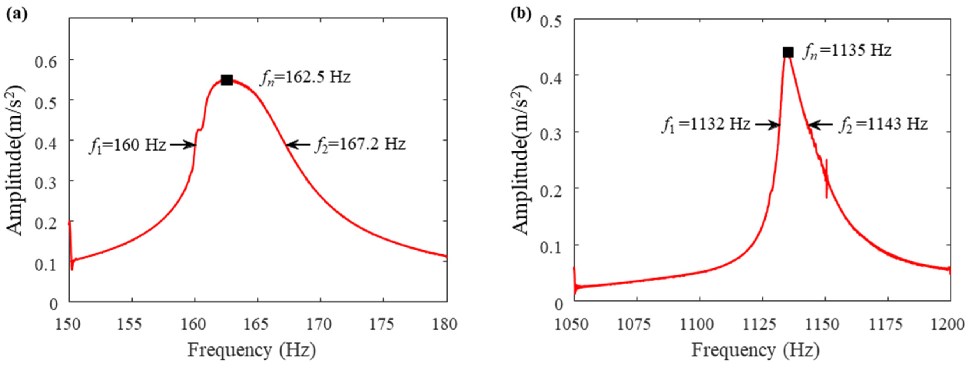
where ζ represents the damping ratio, f1 and f2 represent the frequencies corresponding to the half-power point, f0 represents the resonant frequency of the system, and Δfw represents the half-power bandwidth. When the amplification factor of the system drops to 1/ 2 of its peak value, the width of the corresponding frequency band is called the resonance region. The endpoints on either side of the resonance region have exactly half the maximum power, so the two endpoints are referred to as half-power points, as shown in Figure 2a. In the half-power bandwidth method, also called the 3 dB bandwidth method, the half-power point corresponds exactly to the point on the curve when the peak value drops by 3 dB, as shown in Figure 2b.

2.3. Damping Parameter Identification Test

In this section, the damping ratio of Fe-12Cr-3Al damping alloy materials is determined using the half-power bandwidth method with the sweep frequency testing on a shaker. The specific test process can be summarised as follows. First, the modal frequencies of the specimen are tested in a broad frequency band using the hammering method, and then the test specimen with Fe-12Cr-3Al damping alloy materials is excited with a shaker in the form of a base excitation with a constant amplitude sweep frequency excitation. The sweep frequency band can be selected as 75–125% of the modal frequency of the first order with a proper sweeping speed (usually less than 1 Hz/s).
The response signal is acquired with a lightweight acceleration sensor mounted on the specimen. The acquired time-domain raw data is processed with the short-time Fourier transform (STFT) to obtain the frequency response map under the sweep-frequency excitation. Finally, the half-power bandwidth method is used to identify the damping parameter. Exciting the specimen with sweep-frequency signals containing different orders of nature frequency, then the damping ratio of each order can be obtained.
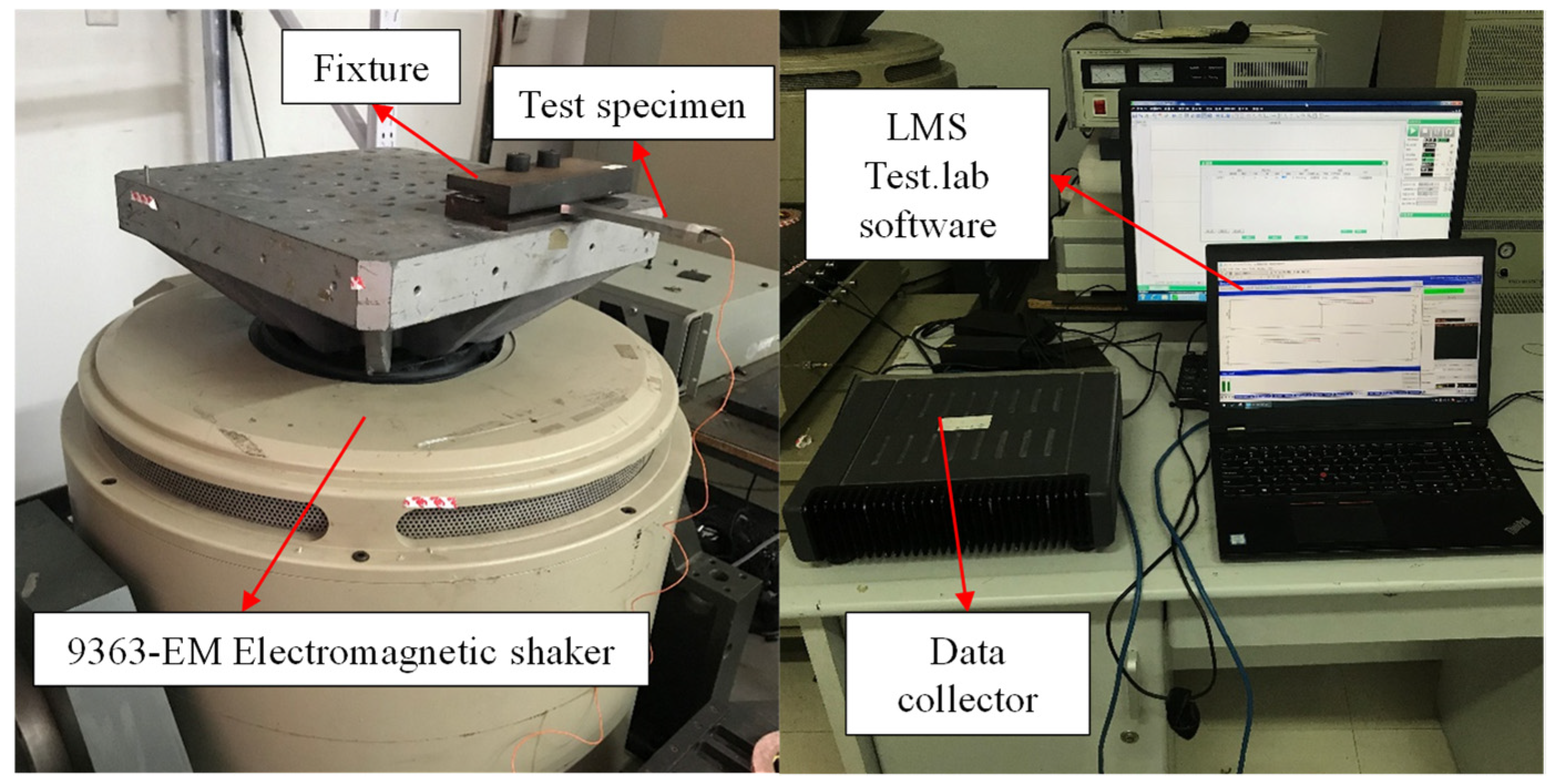
In addition, the PCB 086C01 modal force hammer was used for modal testing, high power amplifier 9363-EM type electromagnetic shaker was used for sweep frequency excitation, a BK-4517 acceleration sensor was used for data acquisition, and LMS Test. lab vibration analysis software (The version number of the software is: Simcenter Testlab 2021.1) was used for data analysis. The shaker and the test system are shown in Figure 3.
The specimens for this test are depicted in Figure 4a. The specimens are categorised into two groups, one group consisting of Fe-12Cr-3Al alloy material and the other consisting of Q235 carbon steel material, with each group comprising three specimens. The specimens are identical in appearance, and the specific geometric dimensions of the specimens are illustrated in Figure 4b, with the units being millimetres.
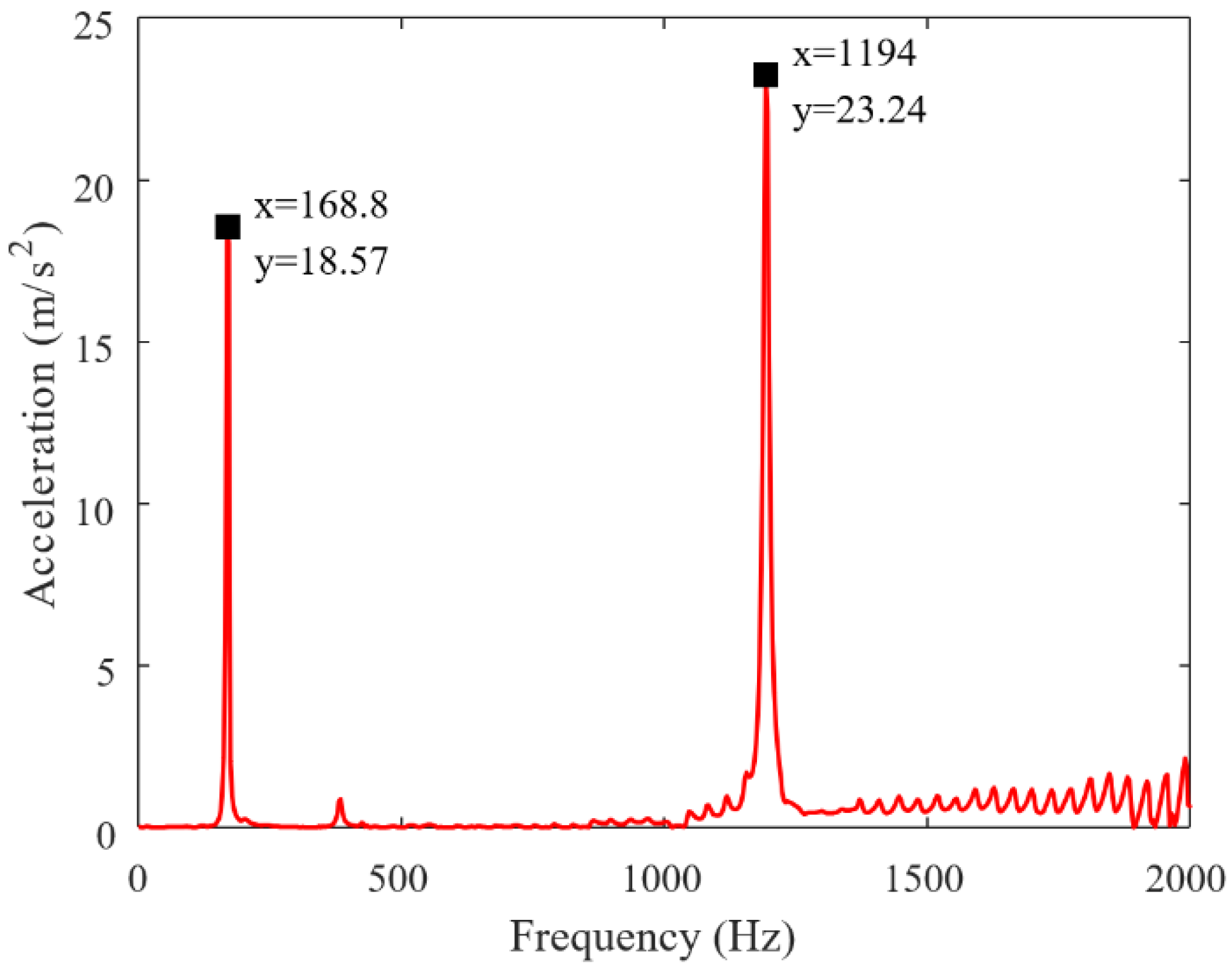
The modal test was conducted by the hammering method to obtain the modal frequency of Fe-12Cr-3Al alloy specimens in a wide frequency band from 0 to 2000 Hz. The specimen is fixed in the cantilevered position on the fixture with a clamping zone of 30 mm. The arrangement of the force hammer and accelerometer measurement points is shown in Figure 5. The spectrum obtained by the hammering method is shown in Figure 6.
The spectrum shows that the force hammer test yields two orders of nature frequency of the damping alloy specimen in the frequency range of 0–2000 Hz, namely 168.8 Hz and 1194 Hz, respectively. On the basis of the two orders of modal frequencies obtained from the hammering method, sweep frequency excitation tests were performed in the range of 75–125% of the two orders of modal frequencies. The damping ratio corresponding to each order of modal frequency of the Fe-12Cr-3Al specimen was determined using the half-power bandwidth method.
Two measurement points were set up in the shaker sweep excitation test, including cantilever beam outer measurement point 1 and cantilever beam root measurement point 2, and the arrangement of the test points is shown in Figure 7. In addition, cantilever beam outer measurement point 1 is located on one side of the free end of the specimen, with a distance of 5 mm from both end faces, while cantilever beam root measurement point 2 is situated on the central axis of the specimen, at a distance of 10 mm from the clamping end face.
The vibration response was obtained by the shaker sweep excitation method, and the half-power bandwidth method was used to identify the damping parameter. The frequency response test results of the Fe-12Cr-3Al damping alloy specimen 1 at measurement points 1 and 2 are shown in Figure 8 and Figure 9, respectively, where fn is the resonance frequency of the corresponding order of the system and f1 and f2 are the frequencies of the half-power points, respectively. Comparing the resonance frequencies derived from the modal test and the swept frequency test, as shown in Table 1, the relative error is about 5%, indicating the test results have good accuracy. The damping ratios corresponding to the two orders of the resonance frequency are obtained and averaged according to Equation (2).
The same test method was used to determine the damping ratios of specimen 2 and specimen 3 and the damping ratio of the Q235 carbon steel specimens, and the test results are summarised in Table 2. The comparison results of the test are shown in Figure 10. “The large deviation in the test results for the Fe-12Cr-3Al specimen 2 can be attributed to the homogeneity of the specimen material, the tightness of the specimen mounting, and the quality of the sensor mounting. It should be especially pointed out that the high damping characteristics of Fe-12Cr-3Al are realised by its own crystal structure, and a poor crystal structure will greatly affect its damping characteristics, which may lead to a large deviation of the damping ratio, so the homogeneity of the specimen material itself is the main influence on the test error. In this paper, the influence of other factors is reduced by testing several times and then taking the average value as the final reference value. According to the average value of the three specimens’ test results, the first-order and second-order damping ratios of Fe-12Cr-3Al alloy are 2.75 and 1.42 times higher than those of Q235 carbon steel, respectively. It can be determined that the overall damping characteristic of the Fe-12Cr-3Al alloy is significantly better than that of Q235 carbon steel.” When the excitation amplitude is fixed, the damping parameter of the Fe-12Cr-3Al alloy decreases with increasing frequency. The results obtained from the test provide a real and reliable database for the subsequent finite element calculation and vibration reduction analysis.

3. Dynamic Characterization of High Damping Alloy Mounted Structures Calculations

The vibration problem of the lubricating oil tank mounting structure is mainly investigated in this paper. As shown in Figure 11, the lubricating oil tank is connected to the aero-engine casing through the mounting structure. The mounting structure is mostly made of ordinary carbon steel with a low damping coefficient and high stiffness. The energy of vibration is often directly transferred from the aero-engine casing to the lubricating oil tank. The use of high damping alloys in the mounting structure can reduce the vibration of the tank system. Therefore, this section investigates the superiority of the vibration reduction performance of the mounting structure with Fe-12Cr-3Al high damping alloy. The real lubricating oil tank mounting structure was used to design the mounting structure fixture, as shown in Figure 12. Here, the surface details of the bolts of the mounting mass block are neglected, and the reason is that such a treatment has a limited impact on the vibration response results of the whole mounting structure. The results in Ref. [21] show that the local details of the threads have less influence on the overall structural vibration characteristics at the macroscale, especially when the relationship between the thread preload and the vibration response is more critical at the macroscale when considering the overall stiffness and damping characteristics of the structure.
The damping coefficient of the high damping alloy is taken as the average value of first-order damping 0.01787 obtained from the tests in Section 2.3, and other specific material parameters are shown in Table 3.
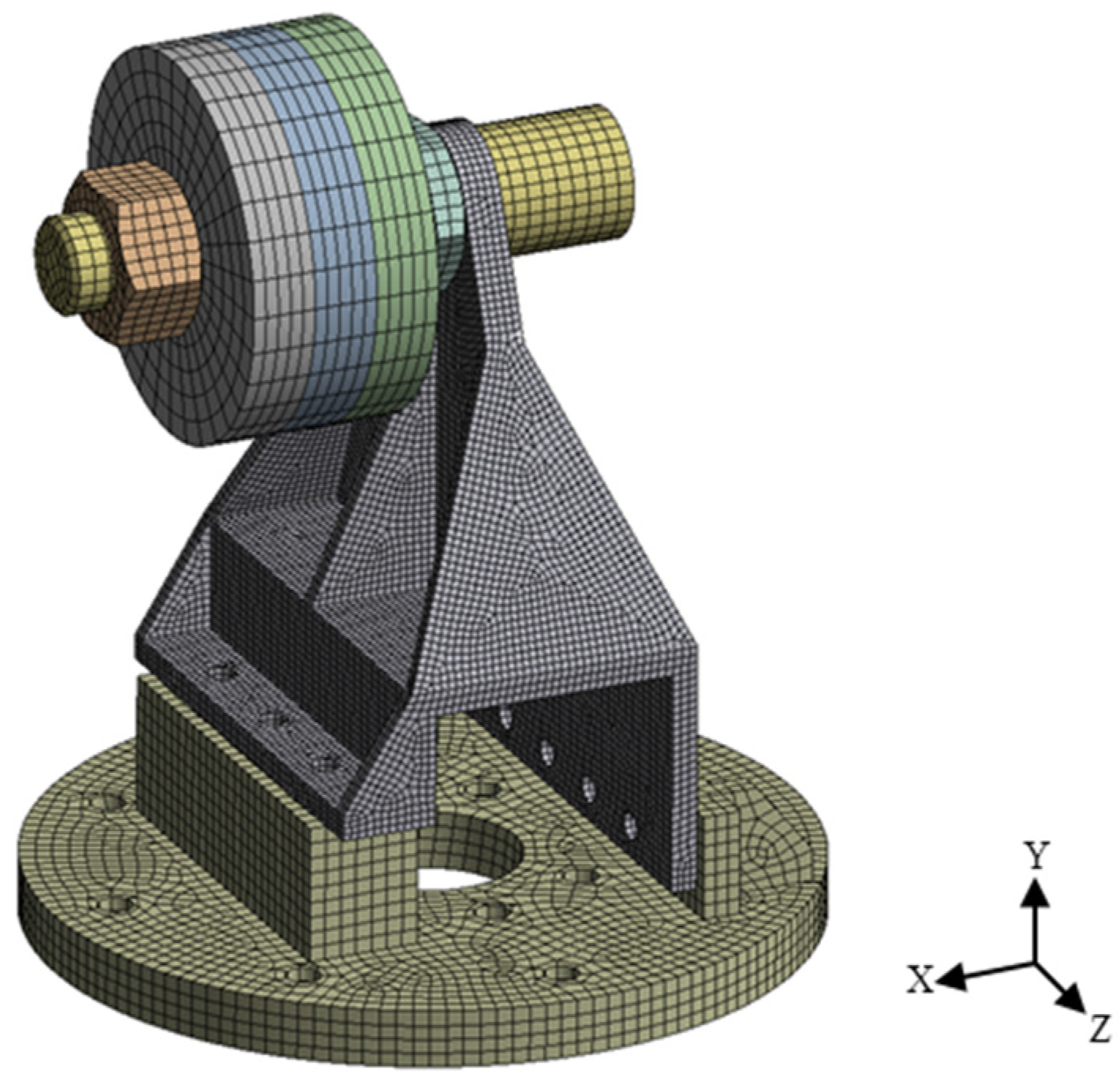
The ANSYS software (The version number of the software is: ANSYS 2023 R1) is utilised to mesh the model and set the boundary condition, and the mesh result is shown in Figure 13. Where the mass blocks use the sweep method, and the remaining parts use the hex dominant method. The mesh of the mounting structure was encrypted as it was the main study component. The body sizing value of the mounting structure is 2.5 mm, and the body sizing value of other parts is 5 mm. The model includes a total of 262,244 nodes and 63,465 elements, with good mesh quality. All contact regions are set as bonded type, and the bottom surface of the base is set as a fixed support surface. In addition, using the Adaptive Convergence function in ANSYS, we performed adaptive mesh refinement based on the solution results to check the convergence of the results [22]. This was done by setting different mesh densities and observing the changes in the solution results until the results stabilised, thus ensuring the convergence and reliability of the analysis results.

3.1. Modal Analysis

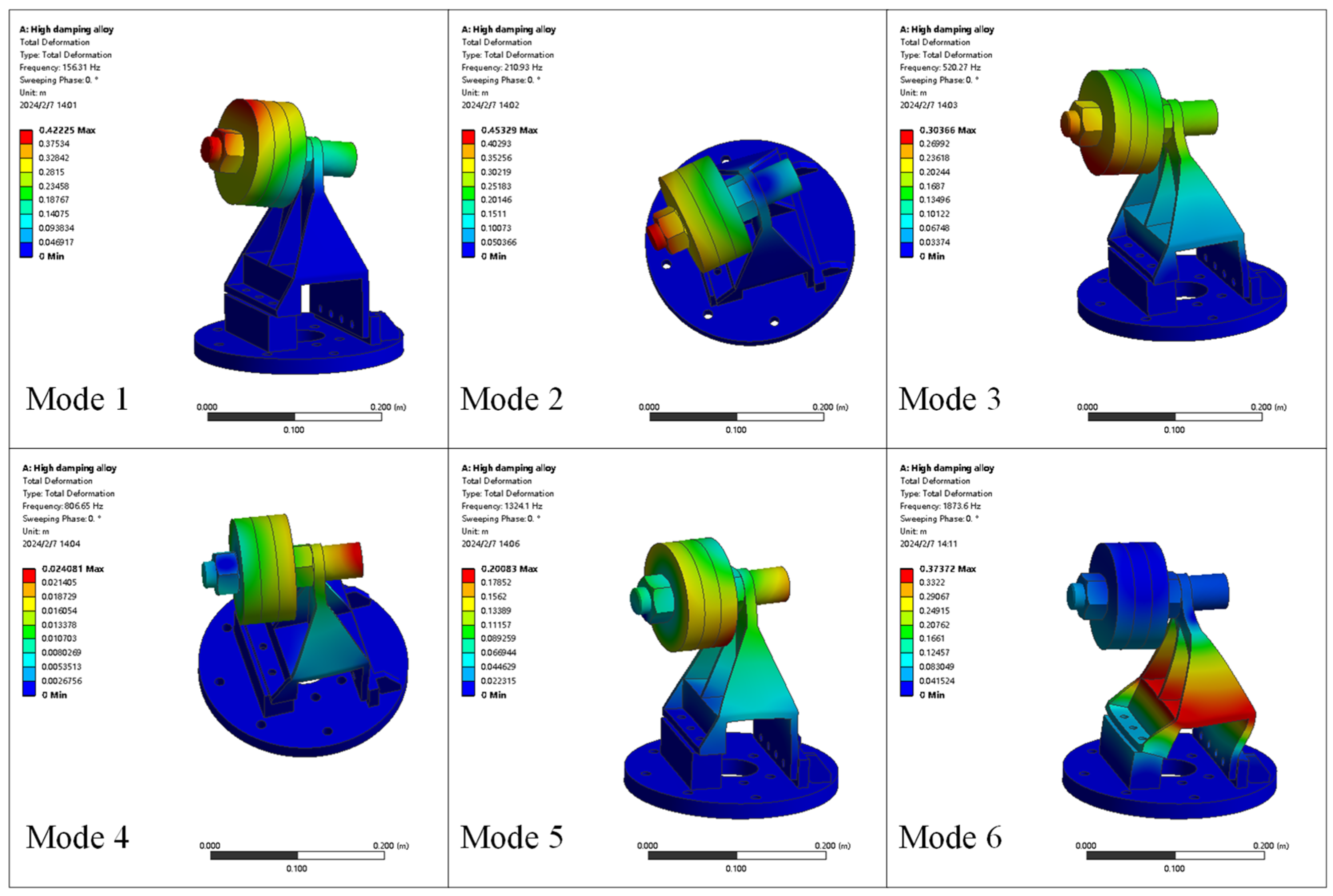
The dynamic characteristics of the high damping alloy material and the carbon steel material mounting structures are calculated using ANSYS software, and the modal frequency comparisons are shown in Table 4. The first 6 orders of vibration patterns of the high damping alloy material and the carbon steel mounting structure are shown in Figure 14 and Figure 15, respectively.
From Table 3, it can be seen that within 0–2100 Hz, the first 6 orders of the intrinsic frequency appeared in the high damping alloy and the carbon steel mounting structures; the modal frequency of the high damping alloy mounting structure is slightly smaller than the carbon steel mounting structure, and the modal damping ratio is about 2.5 times of that of the carbon steel mounting structure. A comparison of Figure 14 and Figure 15 shows that the modal shapes of the mounting structure with two materials are basically the same.

3.2. Harmonic Response Analysis

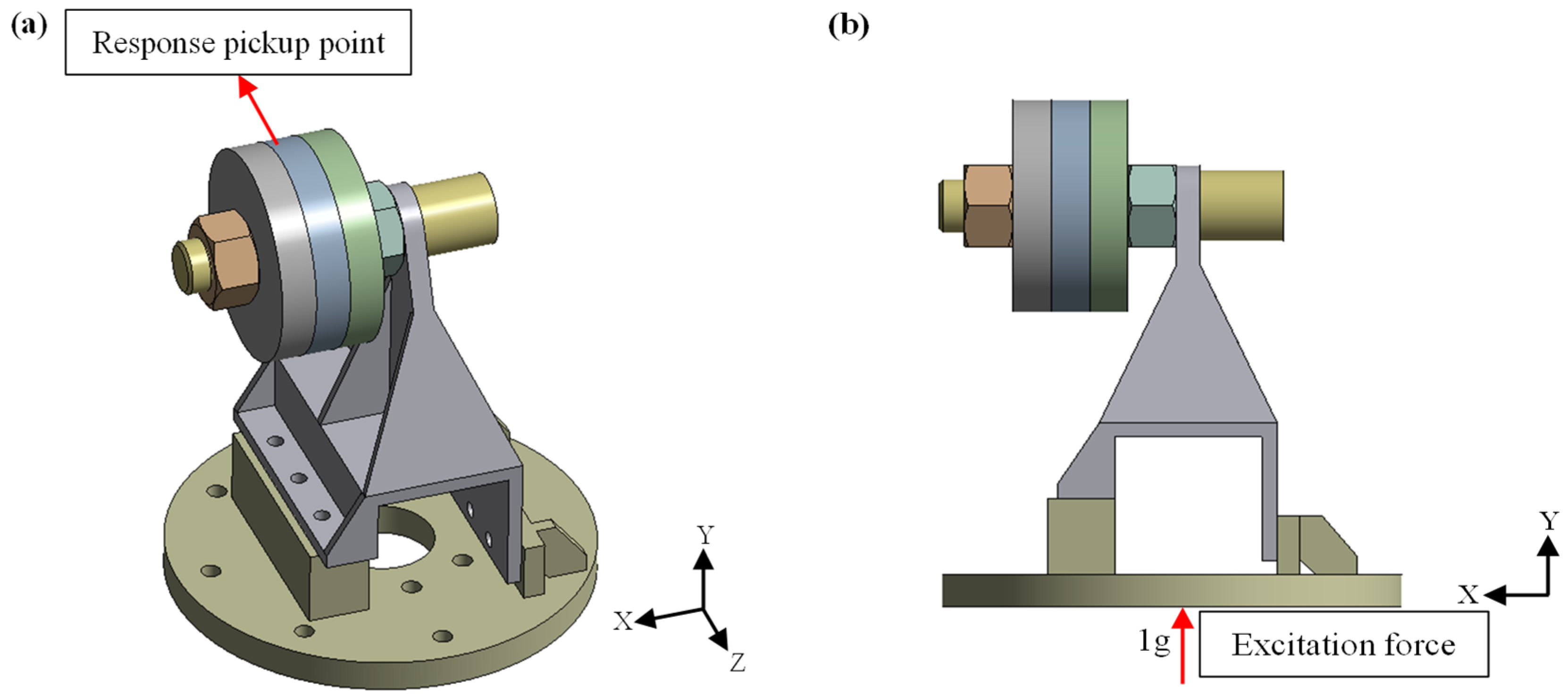
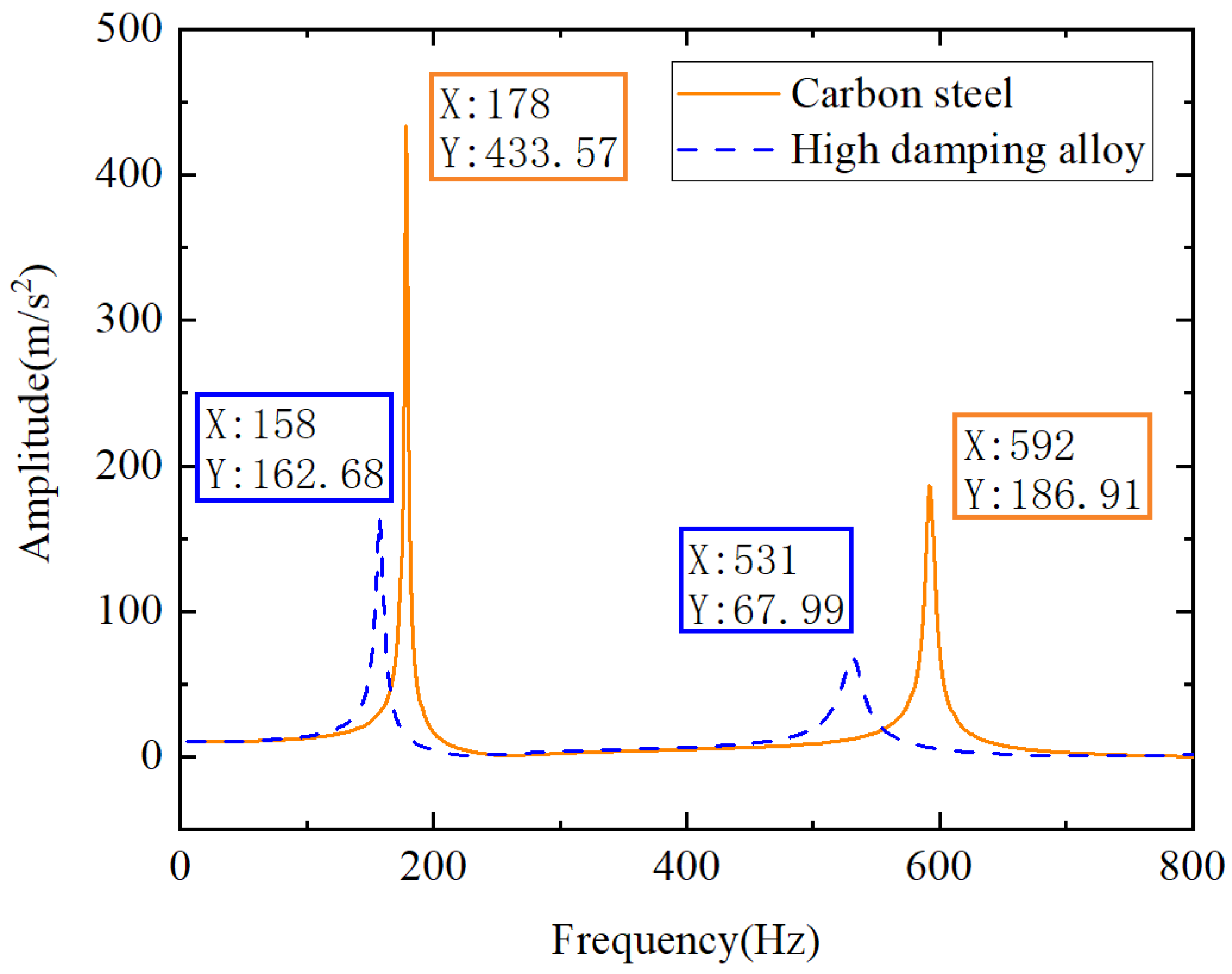
1 g excitation force is applied to the bottom of the mounting structure along the Y-axis direction (perpendicular to the casing direction), and the excitation force sweeps in the range of 0–1500 Hz to compare the acceleration responses of mounting structures made of different materials at the response pickup point. According to the relevant Ref. [23], 1 g is one of the common vibration excitation amplitudes of aerospace power equipment structures, and subsequently, our experimental results also show that this excitation amplitude can obtain the required modal responses. The position of the response pick-up point is shown in Figure 16a, and the position of the excitation force is shown in Figure 16b. Figure 16a shows that the mounting structure has two sets of threaded holes at the position of connection with the base; each set includes three threaded holes; one set of threaded holes at the position directly under the mass block is in the vertical direction, and the other set of threaded holes at the other side of the mounting structure is in the horizontal direction, and the mounting structure is fixed completely by these two sets of bolts in both vertical and horizontal directions. In the simulation, we simulate the axial connection force of the actual bolts by applying a certain pressure on the mapping surface between the bolt spacer and the two connecting surfaces, which greatly simplifies the simulation and saves computation time. Since the focus of this paper is on the overall vibration level of the mounting structure with the mounting mass block installed, it can be assumed that this simplification has a negligible effect on the results. A comparison of the swept response obtained from the finite element calculation is shown in Figure 17, and a comparison of the results is shown in Table 5.
From Table 5, it can be seen that in the range of 0–1500 Hz, the modal frequency of the high damping alloy material mounting structure is comparable to that of the carbon steel material mounting structure, but there is a significant reduction in the vibration response amplitude, and the reduction rate of the vibration amplitude of the corresponding order can reach 60%, respectively.

4. High Damping Alloy Mounting Structure Test

Design and machine a solid prototype based on the fixture model in Section 3. In the fixture system, the mass block is used to simulate the mass loading of the lubricating oil tank and is bolted to the mounting structure, and the mounting structure is bolted to the base simultaneously. The integral mounting structure is fixed on a vertical vibration test rig. Three measurement points were set up in the test, namely the mass block measurement point, the mounting structure measurement point, and the base measurement point, as shown in Figure 18.

4.1. Sweep Test

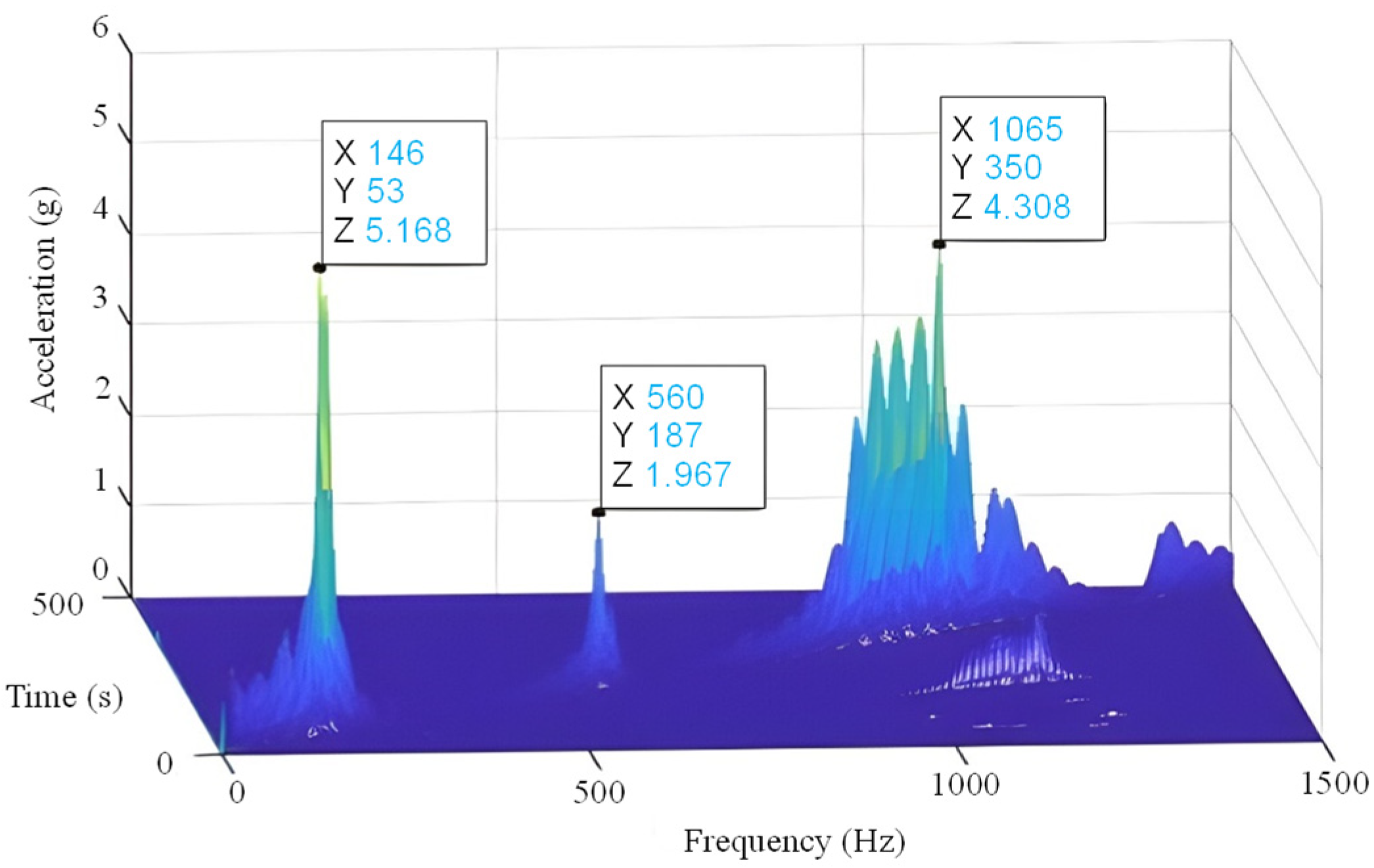
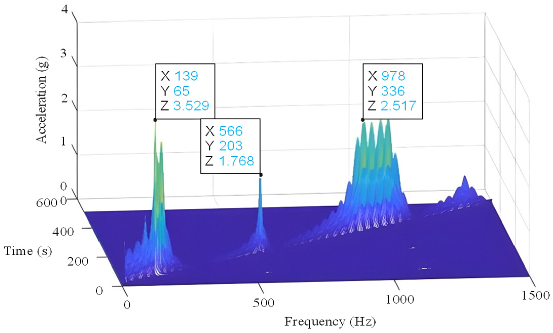
The swept test frequency range of the mounting structure is 0–1500 Hz with an excitation amplitude of 1 g. Extracting the mass block measurement point sweep response data. Comparing the carbon steel material and the high damping alloy material mounting structures sweep response data, the mass block measurement point results are shown in Figure 19 and Figure 20. The comparison results of the vibration response are shown in Table 6.
According to the sweep results of the mass block measurement points in Table 6, the first three natural frequencies of the carbon steel material mounting structure are 146 Hz, 560 Hz, and 1065 Hz, and those of the high damping alloy material mounting structure are 139 Hz, 566 Hz, and 978 Hz. The natural frequency of the high damping alloy material mounting structure is slightly lower than the carbon steel material mounting structure. The first three vibration response amplitudes of high damping alloy material are lower, especially the amplitudes of the first and third orders. The degree of vibration reduction is relatively large, greater than 30%. The test results verify the reasonableness of the finite element calculation results, and the vibration reduction effect of high damping alloy material is better.

4.2. Fixed Frequency Test

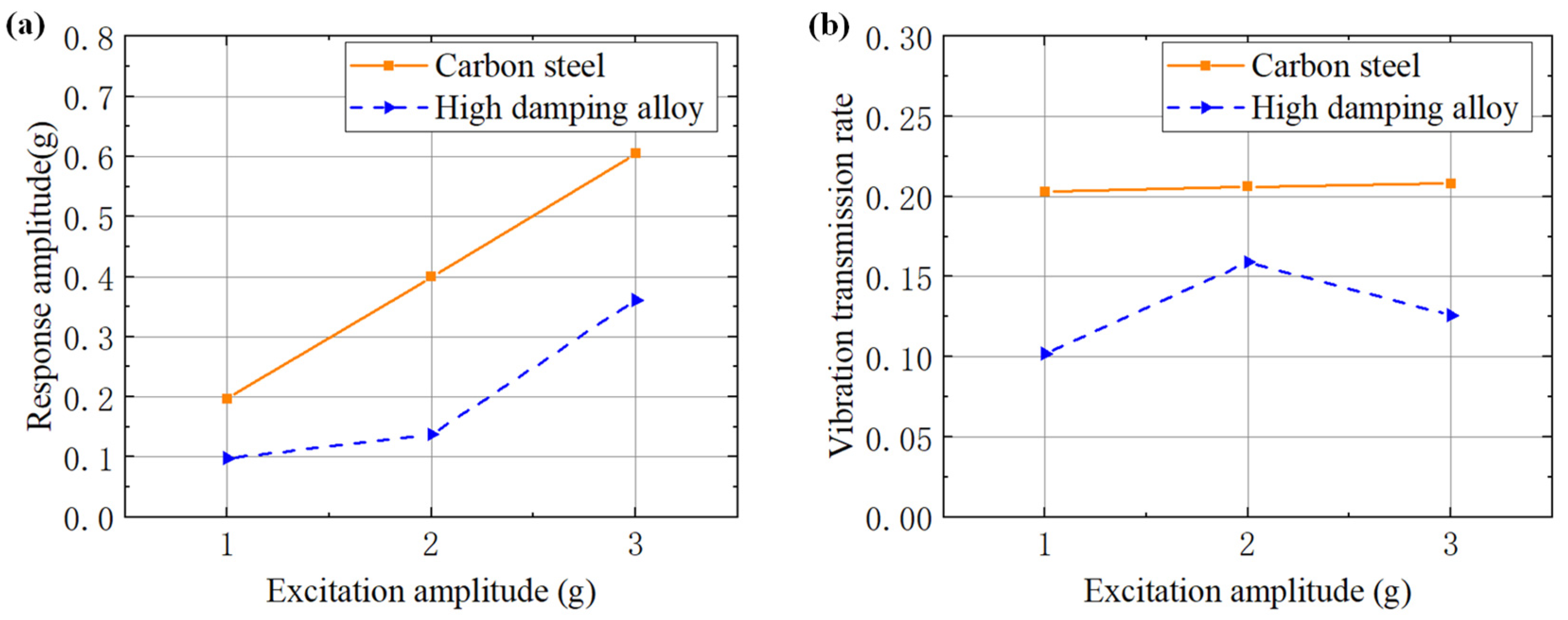
The maximum speed of a certain aero-engine is 18,800 rpm, which corresponds to the frequency of 315 Hz. The fixed-frequency vibration test under the simulated maximum speed is carried out. Under the excitation amplitude of 1 g, 2 g, and 3 g, respectively, the carbon steel material and high damping alloy material mounting structures of the vibration response and transmission rate of the different measurement points are compared, and the comparison results are shown in Figure 21 and Table 7.
According to the fixed-frequency test results of mounting structures and comparing the high damping alloy material mounting structure with the carbon steel material mounting structure, there is a reduction in the vibration response at the mass block, and the reduction rate is close to 50%. The transmission rates of the carbon steel material and the high damping alloy material mounting structures are maintained at about 0.2 and 0.12, respectively. The transmission rate at different excitation amplitudes can be reduced by up to 49.8%, 22.8%, and 39.4%, respectively. In addition, a comparative analysis of the vibration response of the base and the mounting structure shows that the best damping effect of the high damping alloy material mounting structure occurs at an excitation amplitude of 2 g, which may be attributed to the nonlinear performance of the high damping material.

5. Conclusions

In this paper, based on the identification of damping parameters of Fe-12Cr-3Al alloy materials, dynamic characteristic calculations and experimental tests have been carried out on the high damping alloy mounting structures and carbon steel mounting structures. Comprehensive finite element calculation results and swept frequency test results show that, in the frequency range of 0–1500 Hz, the modal frequency of the high damping alloy material mounting structure is slightly reduced compared to that of the carbon steel material mounting structure. The response amplitude corresponding to the different order is significantly reduced, and the amplitude reduction rate is about 30%. The fixed frequency test results show that the vibration transmission rate of the high damping alloy mounting structure can be reduced by 40% compared with the carbon steel mounting structure. At the same time, the experimental results verify the reasonableness of the finite element calculation, and the selected high damping alloy material applied to the mounting structure has a better vibration reduction effect, which can provide a reference for the application of high damping alloy material to the vibration reduction design of the mounting structure of aero-engines.

Author Contributions

Conceptualization, J.L. and W.L.; Methodology, H.Z. and Q.H.; Software, H.C.; Formal analysis, H.Z. and Q.H.; Resources, J.L. and W.L.; Data curation, H.C.; Writing—original draft, H.Z.; Writing—review & editing, J.L., H.C. and Y.Z.; Supervision, H.M. and Q.H.; Project administration, J.L. and H.M.; Funding acquisition, J.L., W.L. and Q.H. All authors have read and agreed to the published version of the manuscript.

Funding

This research was funded by National Key Research and Development Program of China grant number 2023YFC2907205, National Science and Technology Major Project of China grant number J2019-I-0008-0008 and J2019-IV-0002-0069, The Fundamental Research Funds for the Central Universities under Grant grant number N2303016, Science and Technology Plan Project of Liaoning Province Grant grant number 2022JH1/10800057.

Institutional Review Board Statement

Not applicable.

Informed Consent Statement

Not applicable.

Data Availability Statement

The original contributions presented in the study are included in the article, further inquiries can be directed to the corresponding author.

Conflicts of Interest

Author Hongxu Zhang was employed by the Shenyang Academy of Instrumentation Science Co., Ltd. The remaining authors declare that the research was conducted in the absence of any commercial or financial relationships that could be construed as a potential conflict of interest.

References

  1. Hussain, T.; Sarangi, N.; Sivaramakrishna, M.; Kumar, M.U. A Simulation Study of Lubricating Oil Pump for an Aero Engine. J. Mech. Eng. (JMechE) 2021, 18, 113–129. [Google Scholar] [CrossRef]
  2. Schaller, R. Metal matrix composites, a smart choice for high damping materials. J. Alloys Compd. 2003, 355, 131–135. [Google Scholar] [CrossRef]
  3. Huang, W.; Wang, Y.; Peng, H.; Wen, Y. Effect of up-quenching time on damping capacity in a ductile Cu-16.59 Al-10.55 Mn shape memory alloy. Mater. Res. Express 2019, 6, 095703. [Google Scholar] [CrossRef]
  4. Xiong, W.; Zhu, X.; Liu, Z.; Fang, Y.; Zhu, X.; Wang, N.; Xu, Y. Microstructure regulation and internal friction behavior of Fe45Mn20Cr15Co20 duplex high-entropy damping alloy. Mater. Today Commun. 2024, 38, 107586. [Google Scholar] [CrossRef]
  5. Ritchie, I.G.; Pan, Z.L.; Sprungmann, K.W.; Schmidt, H.K.; Dutton, R. High damping alloys—The Metallurgist’s cure for unwanted vibrations. Can. Metall. Q. 1987, 26, 239–250. [Google Scholar] [CrossRef]
  6. Igata, N. Applications of high damping stainless alloy (HIDAS). Key Eng. Mater. 2006, 319, 209–216. [Google Scholar] [CrossRef]
  7. Qian, B.; Peng, H.; Wen, Y. A novel sandwich Fe-Mn damping alloy with ferrite shell prepared by vacuum annealing. Smart Mater. Struct. 2018, 27, 045005. [Google Scholar] [CrossRef]
  8. Emdadi, A.; Nartey, M.A.; Xu, Y.G.; Golovin, I.S. Study of damping capacity of Fe–5.4 Al–0.05 Ti alloy. J. Alloys Compd. 2015, 653, 460–467. [Google Scholar] [CrossRef]
  9. Sun, M.; Wang, X.; Wang, L.; Wang, H.; Jiang, W.; Liu, W.; Hao, T.; Gao, R.; Gao, Y.; Zhang, T.; et al. High-temperature order-disorder phase transition in Fe-18Ga alloy evaluated by internal friction method. J. Alloys Compd. 2018, 750, 669–676. [Google Scholar] [CrossRef]
  10. Fantozzi, G.; Esnouf, C.; Reihani, S.S.; Revel, G. Anelastic behaviour of plastically deformed high purity magnesium between 10 and 500 K. Acta Metall. 1984, 32, 2175–2183. [Google Scholar] [CrossRef]
  11. Sun, M.; Wang, X.; Wang, L.; Wang, H.; Jiang, W.; Liu, W.; Hao, T.; Gao, R.; Gao, Y.; Zhang, T.; et al. Influence of alloy elements (Mo, Nb, Ti) on the strength and damping capacity of Fe-Cr based alloy. Mater. Sci. Eng. A 2016, 667, 326–331. [Google Scholar]
  12. O’Toole, J.F., Jr. An Investigation of the Damping Properties of Vacrosil-010. Ph.D. Thesis, Institutional Archive of the Naval Postgraduate School, Monterey, CA, USA, 1986. [Google Scholar]
  13. Azcoïtia, C.; Karimi, A. Magnetomechanical damping in Fe–Cr alloys and effect of Al and Mo addition. J. Alloys Compd. 2000, 310, 160–164. [Google Scholar] [CrossRef]
  14. Mohamed, A.K.; Zadorozhnyy, M.Y.; Saveliev, D.V.; Chudakov, I.B.; Golovin, I.S. Damping capacity, magnetic and mechanical properties of Fe-18Cr alloy. J. Magn. Magn. Mater. 2020, 494, 165777. [Google Scholar] [CrossRef]
  15. Duan, L.; Pan, D.; Wang, H.; Wang, J. Investigation of the effect of alloying elements on damping capacity and magnetic domain structure of Fe-Cr-Al based vibration damping alloys. J. Alloys Compd. 2017, 695, 1547–1554. [Google Scholar] [CrossRef]
  16. Liu, R.; Sun, H.; Liu, X.; Yan, W.; Jiang, X. Effect of Gd on microstructure, mechanical properties and damping properties of Fe-Cr-Al alloys. Mater. Charact. 2022, 187, 111841. [Google Scholar] [CrossRef]
  17. Adhikari, S.; Woodhouse, J. Identification of damping: Part 1, viscous damping. J. Sound Vib. 2001, 243, 43–61. [Google Scholar] [CrossRef]
  18. Ivancic, F.; Palazotto, A. Experimental considerations for determining the damping coefficients of hard coatings. J. Aerosp. Eng. 2005, 18, 8–17. [Google Scholar] [CrossRef]
  19. Ewins, D.J. Modal Testing: Theory, Practice and Application; John Wiley & Sons: Hoboken, NJ, USA, 2009. [Google Scholar]
  20. ASTM E756-05(2017); Standard Test Method for Measuring Vibration-Damping Properties of Materials. ASTM International: West Conshohocken, PA, USA, 2010.
  21. Xu, W.; Cheng, Q.; Yang, C.; Li, Y. Dynamic analysis and looseness evaluation of bolted connection under vibration of machine tools. Int. J. Adv. Manuf. Technol. 2021, 124, 3761–3770. [Google Scholar] [CrossRef]
  22. Zhao, H.; Fu, C.; Zhang, Y.; Zhu, W.; Lu, K.; Francis, E.M. Dimensional decomposition-aided metamodels for uncertainty quantification and optimization in engineering: A review. Comput. Methods Appl. Mech. Eng. 2024, 428, 117098. [Google Scholar] [CrossRef]
  23. Peng, H.; Zou, B.; Yang, J.; Fu, R.; Ding, X.; Zhang, D.; Bin, G. Simulated vibration characterization of the aero-turbine engine vibration isolation system under broadband random excitation. Mech. Sci. 2024, 15, 461–472. [Google Scholar] [CrossRef]
Figure 1. The AL-31FN aero-engine.
Applsci 14 11056 g001
Figure 2. The principle of the half-power bandwidth method: (a) half-power bandwidth and (b) 3 dB bandwidth.
Applsci 14 11056 g002
Figure 3. The shaker and test system.
Applsci 14 11056 g003
Figure 4. The test specimens: (a) Specimens drawing and (b) Schematic diagram of geometric dimensions.
Applsci 14 11056 g004
Figure 5. The knocking point and measuring point of the acceleration sensor.
Applsci 14 11056 g005
Figure 6. The spectrum of damping test.
Applsci 14 11056 g006
Figure 7. The measurement points of the sweep response experiment: (a) Measurement point 1 and (b) Measurement point 2.
Applsci 14 11056 g007
Figure 8. The frequency response of measuring point 1: (a) first order, (b) second order.
Applsci 14 11056 g008
Figure 9. The frequency response of measuring point 2: (a) first order, (b) second order.
Applsci 14 11056 g009
Figure 10. The comparison of the test results (a) First order damping ratio, (b) Second order damping ratio.
Applsci 14 11056 g010
Figure 11. The mounting structure of the lubricating oil tank.
Applsci 14 11056 g011
Figure 12. The tooling systems of the mounting structure.
Applsci 14 11056 g012
Figure 13. The mesh result.
Applsci 14 11056 g013
Figure 14. First 6 orders of modal shapes of high damping alloy mounting structure.
Applsci 14 11056 g014
Figure 15. First 6 orders of modal shapes of carbon steel mounting structure.
Applsci 14 11056 g015
Figure 16. The position of the response pickup point and the application position of the excitation force (a) respond to the pickup point location, (b) position of the excitation force.
Applsci 14 11056 g016
Figure 17. The comparison of sweep response comparison.
Applsci 14 11056 g017
Figure 18. The position of measurement points of the installation structure.
Applsci 14 11056 g018
Figure 19. The waterfall of the mass block measurement points of the Q235 mounting structure.
Applsci 14 11056 g019
Figure 20. The waterfall of the mass block measurement points of the Fe-12Cr-3Al mounting structure.
Applsci 14 11056 g020
Figure 21. The comparison of test results (a) Response amplitude at the mass block measurement point, (b) Vibration transmission rate.
Applsci 14 11056 g021
Table 1. The resonance frequency and damping ratio of Fe-12Cr-3Al.
Modal OrderMeasurement PointsModal TestSweep TestRelative
Error
Damping RatioAverage
First orderPoint 1168.8 Hz162.5 Hz3.73%0.022150.02234
Point 2168.8 Hz162.0 Hz4.03%0.02253
Second orderPoint 11194.0 Hz1135 Hz4.94%0.004840.00484
Point 21194.0 Hz1134 Hz5.02%0.00485
Table 2. The damping ratio test results of Fe-12Cr-3Al and Q235.
Modal OrderMaterialDamping Ratio
Specimen 1Specimen 2Specimen 3Average
First orderFe-12Cr-3Al0.022340.012780.018480.01787
Q2350.006430.006550.006530.00650
Second orderFe-12Cr-3Al0.004840.005170.004200.00474
Q2350.003530.003340.003140.00334
Table 3. The parameter comparison of high damping alloy material and carbon steel material.
MaterialsModulus of
Elasticity (MPa)
Densities (kg/m3)Poisson’s
Ratio
Yield Strength (MPa)Modal
Damping Ratio
Fe-12Cr-3Al1.62 × 10574600.284500.01787
Q235 2.10 × 10577500.32350.0065
Table 4. The modal analysis results of the comparison of high damping alloy mounting structure and carbon steel material mounting structure.
Modal OrderHigh Damping AlloyCarbon Steel
Modal Frequency/HzModal
Damping Ratio
Modal Frequency/HzModal
Damping Ratio
First order156.310.01726176.840.006491
Second order210.930.01681236.460.006489
Third order520.270.01623580.430.006486
Fourth order806.650.01556890.320.006489
Fifth order1324.10.013111417.60.006484
Sixth order1873.60.014452012.70.006488
Table 5. The data comparison of sweep response comparison.
Modal
Order
High Damping AlloyCarbon SteelAmplitude Reduction Rate
Modal
Frequency/Hz
Response
Amplitude/m/s2
Modal
Frequency/Hz
Response
Amplitude/m/s2
1st order158162.68178433.5762.48%
3rd order53167.99592186.9163.62%
Table 6. The comparison of the mass block measurement point results of the mounting structure.
ParametersMaterialsFirst
Order
Second
Order
Third
Order
Natural FrequencyCarbon Steel146 Hz560 Hz1065 Hz
High Damping Alloy139 Hz566 Hz978 Hz
Response AmplitudeCarbon Steel5.168 g1.967 g4.308 g
High Damping Alloy3.529 g1.768 g2.517 g
Reduction Rate---31.7%10.1%41.5%
Table 7. The fixed frequency test results of the mounting structure.
PartsMaterialsExcitation Amplitude
1 g2 g3 g
BaseCarbon steel0.97041.942.91
High damping alloy0.9541.2932.864
Mounting StructureCarbon steel0.92641.8492.772
High damping alloy0.92381.2522.772
Mass BlockCarbon steel0.19720.39940.6047
High damping alloy0.097750.13760.3611
Transmission RateCarbon steel0.2030.2060.208
High damping alloy0.1020.1590.126
Reduction Rate 49.8%22.8%39.4%
Disclaimer/Publisher’s Note: The statements, opinions and data contained in all publications are solely those of the individual author(s) and contributor(s) and not of MDPI and/or the editor(s). MDPI and/or the editor(s) disclaim responsibility for any injury to people or property resulting from any ideas, methods, instructions or products referred to in the content.