Article

Delayed-Expansion Capsule Sealing Material for Coal Mine Overburden Isolated Grouting

1
School of Mines, China University of Mining & Technology, Xuzhou 221116, China
2
State Key Laboratory for Fine Exploration and Intelligent Development of Coal Resources, China University of Mining & Technology, Xuzhou 221116, China
*
Author to whom correspondence should be addressed.
Appl. Sci. 2024, 14(24), 11595; https://doi.org/10.3390/app142411595
Submission received: 29 October 2024 / Revised: 30 November 2024 / Accepted: 8 December 2024 / Published: 12 December 2024

Abstract

:
Grouting technology is an important method of ground reinforcement and can effectively improve the stability of engineering rock mass. During overburden isolated grouting in coal mines, the influence of unexpected fractures may lead to substantial grout leakage, resulting in ineffective grouting. The existing natural sedimentation sealing method is mainly applicable to small fractures and low grout flow, while the chemical-reagent rapid-sealing method can cause grouting channel blocking, making it less suitable for overburden isolated grouting. This paper proposes a “capsule” sealing method, detailing the preparation of the sealing material and evaluation of its properties through testing. The sealing material, prepared using the air suspension method, was coated with paraffin on a superabsorbent polymer (SAP) material, which has delayed expansion characteristics. Although this material does not expand within the grouting fractures of overburden rock, it expands rapidly upon entering the leakage channel, accumulating within the channel to achieve effective sealing. A simulation experimental system was designed to simulate the sealing of the slurry leakage channel, and the sealing characteristics were experimentally investigated. Under consistent particle size conditions, a higher film cover ratio led to a more pronounced delayed expansion effect and extended the time required for the sealing material to achieve its maximum expansion. When the content of sealing material with particle sizes of 20 mesh, 40 mesh, and 60 mesh, and a film ratio of 20% was 1.0%, the fractures below 4 mm were effectively sealed. When the fracture aperture is 4–6 mm, the sealing material with a covering ratio of 20% or 30% should have a minimum content of 1.5%, while the sealing material with a covering ratio of 50% should have a minimum content of 2.0%. The findings of this study outline an effective prevention and control method for the sealing of abnormal slurry leakage in overburden isolated grouting engineering.

1. Introduction

Mining subsidence caused by the development of coal resources is a major cause of environmental problems in mining areas [1,2,3]. Fill mining is an important technical approach for addressing mining subsidence. After decades of development, filling and mining methods such as solid filling, paste filling, high-water material filling, and overburden isolation grouting filling have been gradually developed [4,5,6,7]. Among them, overburden isolation grouting and filling technology have been extensively applied [8,9,10], and can effectively control surface subsidence and protect ground structures through the implementation of high-pressure grouting and the filling of mining fracture cavities under the selected key layer, forming a compaction-bearing structure to support the key layer. However, during the grouting process, abnormal fracture channels connect under the effect of faults, geological boreholes, and other unfavorable factors. This results in the failure of the filling cavity’s tightness and the spread and leakage of slurry along the overburden rock fracture channels, leading to the loss of pressure in the filling cavity, which compromises the effectiveness of control measures. Therefore, a method for sealing abnormal fractures during the grouting process is an important prerequisite for ensuring the effect of grouting and filling.
There are two main types of sealing methods for rock fracture channels, namely, the natural sedimentary slow-sealing method and the chemical agent rapid-sealing method [11]. The principle of natural deposition slow-sealing method is straightforward: the solid–liquid two-phase flow slurry is continuously separated and deposited during the flow process, and the solid particles are used to seal the fracture channel. The treatment process of this method is slow, and the control process is complex. Excessive grouting pressure can easily cause the reopening and expansion of sealed fracture channels, undermining the effectiveness of the sealing process. However, because the pressure and flow rate of overburden isolation grouting are high, this method is not suitable for fracture sealing in this grouting process. Rapid sealing with chemical reagents relies on chemical reactions either between the reagents themselves or between the reagents and substances within rock fractures. This process quickly solidifies the reagents used to fill the fractures, with some reagents specifically reacting with fracture minerals to enhance sealing effectiveness. Reagents and ions in the rock fractures react with each other to generate insoluble substances, which precipitate in the fractures and play a role in sealing.
As for overburden isolation grouting engineering, the slurry is required to spread as far as possible along the dominant flow channel to achieve a better filling effect, with fewer boreholes. Therefore, directly using a quick-setting sealing material can easily lead to clogging in the boreholes or in the dominant flow channels before reaching the leakage fractures, resulting in the failure of the subsequent filling process. In summary, the natural sedimentary slow-sealing method is suitable for low grouting pressure and flow conditions, which is significantly different from the coal mine overburden isolated grouting. The rapid sealing method of chemical reagents may cause the problem of grouting filling channel blockage, and face problems such as high cost and potential adverse effects on the environment. Therefore, a suitable sealing material must be developed to accommodate the challenges posed by large fractures and high flow rates in coal mine overburden isolation grouting run-through fractures.
There are many rock fracture sealing materials, and different materials have their own unique properties and application scenarios. Among them, some traditional sealing materials are widely used in sealing rock fractures. However, with the development of technology and the diversification of needs, various new materials have gradually emerged. Among them, the high-water-absorption resin (SAP) material plays a unique role in many fields owing to its properties [12,13]. Known for their high swelling capacity upon water absorption, SAP materials hold significant potential for fracture sealing applications and have garnered substantial interest from researchers.
Shahid et al. [14] investigated the effect of four different SAP concentrations (0.2%, 0.4%, 0.6%, and 0.8% by weight of cement) on the performance of hybrid fiber concrete (HFC) using highly absorbent polymers (SAPs) to evaluate the efficiency of crack healing based on the rate of crack closure and strength restoration. They reported that, for all investigated SAP concentrations, cracks measuring up to 465 μm were completely sealed. Yang et al. [15] analyzed the crack self-sealing mechanism of hydrogel, providing a comprehensive review of hydrogel design methods for enhancing crack self-sealing. They outlined the influence of hydrogel on concrete’s impermeability, mechanics, and durability recovery. Additionally, they discussed the testing and evaluation techniques for crack healing and sealing, offering insights into practical applications and performance assessment. De Belie et al. [16] were the first to investigate the self-healing efficiency of SAP-merged concrete and reported that SAP can seal cracks immediately. Snoeck et al. [17] used microfibers and 1.0% SAP in concrete with a relative humidity greater than 60%. The experimental concrete exhibited a faster healing rate compared with conventional concrete while maintaining all of its original properties, showing no signs of degradation. Li et al. [18] investigated the synergistic effect of highly absorbent polymers (SAPs) and crystalline admixtures (CAs) on the closure of macroscopic cracks (>0.5 mm in width) in cementitious materials (CBMs). The combination of CA and SAP resulted in good self-healing ability and satisfactory crack sealing. Hassi et al. [19] extensively evaluated the performance of highly absorbent polymers (SAPs) as self-healing agents for addressing macro-cracks in ultra-high-performance concrete (UHPC). Their assessment consisted of measurements of the crack closure rate, recovery of compressive strength, and detailed stereo-microscopic analysis. Their results revealed that the SAP significantly enhanced the self-healing ability of UHPC. Lefever et al. [20] conducted a comparative study between a mixture of SAP and nano-silica added to concrete and samples containing only nano-silica and reported that the former was able to achieve 100% crack closure.
Feng et al. [21] investigated and designed a novel capsule. The core material of the capsule is cement or a combination of cement and highly absorbent polymers (SAPs). The core material in the capsule reacts with water, exhibiting high sealing rates for cracks up to 400 μm, and even bridging internal cracks with widths over 200 μm. Chindasiriphan et al. [22] assessed the feasibility of using highly absorbent polymers (SAPs) to enhance the self-healing properties of microbial-induced calcium carbonate precipitation (MICP) in cementitious materials and reported that the incorporation of SAP into the MICP system reduced the MICP bacterial content without affecting the self-healing properties. Pelto et al. [23] used a fluidized bed-spraying process to coat highly absorbent polymers and characterized the encapsulated SAP to determine its solubility and quantify the delayed effect of water and Ca(OH)2 solution absorption. Their results revealed that the swelling of mortar samples was substantially delayed, though this effect was brief. Importantly, the SAP film coating did not hinder the mortar’s self-sealing efficiency. Lauch et al. [24] reported that fibers containing SAP admixtures enhanced the self-healing ability of concrete, confirming the potential value of this material in crack sealing.
Although highly absorbent resin expansion materials play an important role in many fields, their application in fracture sealing for overburden isolation grouting and filling engineering remains a novel challenge. Although the expansion property of SAP material is effective for large flow rates and large open fractures, rapid expansion can lead to premature sealing within the pipe or borehole, preventing it from adequately entering the fracture that requires sealing. Therefore, a method for effectively extending the SAP material’s expansion time must be investigated.
This study considered fracture sealing in overburden isolation grouting and filling as the research background and developed a method for sealing fractures using delayed expansion materials based on SAP. This study involved preparing the material, investigating the sealing material’s expansion capacity and fluidity, designing a fracture sealing model, and conducting experimental research. The results provide a theoretical basis for addressing the challenges of abnormal flow channel sealing in overburden isolation grouting and filling engineering.

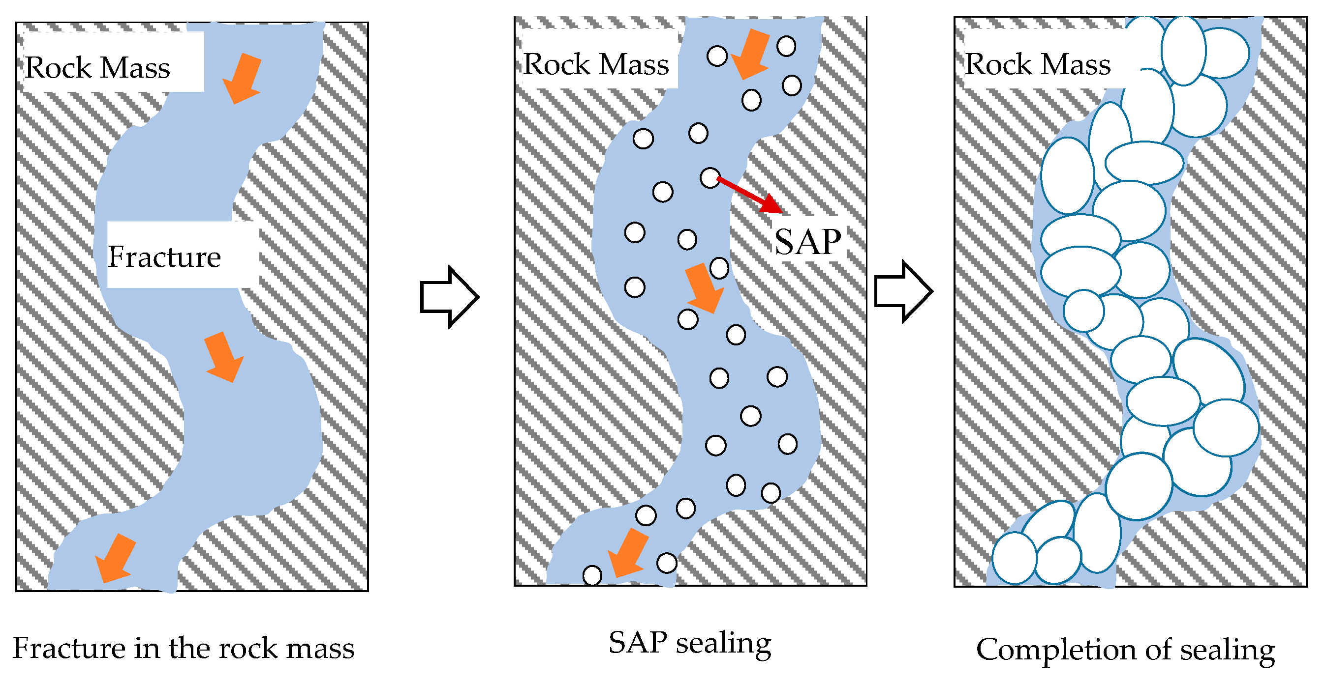
2. Sealing Mechanism

The SAP material is a polymer known for its exceptional water absorption and retention properties, with low cross-linking density that makes it stable and only minimally soluble in water [25,26,27,28,29,30]. Owing to its high water absorption and high expansion capabilities, SAP incorporates a three-dimensional network structure densely packed with strong hydrophilic groups, such as amino and carboxyl groups [31,32,33,34,35,36]. This network allows SAP to absorb water at a rate hundreds of times its own mass, beginning the expansion process immediately upon contact with water, which results in an extremely rapid water absorption rate. The highly absorbent resin SAP swells into an elastic gel with strength. The SAP material has good water retention capability under normal temperature and pressure and does not lose water easily under heating and loading conditions.
The elastic gel volume of SAP after absorbing water can reach hundreds of times that of the raw material, which is suitable for sealing the running slurry channel. However, SAP has very fast expansion time, expanding rapidly upon contact with water, with the expansion completing in just over ten seconds, which does not satisfy the above-mentioned sealing purpose.
In this study, a sealing material was developed by unevenly coating the surface of SAP with a thin layer of hydrophobic paraffin wax. The plugging material is composed of hydrophobic paraffin wax and SAP; the paraffin is insoluble in water and has a water-blocking effect. The paraffin wax wrapped around the surface of SAP prevents SAP from coming into contact with water and swelling do not occur. It should be noted that the film covering of SAP is not absolutely uniform, and certain SAP particles with less coating will come into contact with water through water pressure over time. Expansion then occurs in these particles, increasing the area of contact between water and SAP and aggravating the swelling effect. The increase in the expansion force will destroy more paraffin films, and eventually the SAP will be fully exposed to water, expanding rapidly in a short time. In this way, the purpose of delayed expansion can be achieved. Through the adjustment of the mixing ratio, the expansion time can be controlled, so that the sealing material expands after flowing into the leakage fracture. This time-delayed expansion mechanism is designed to satisfy specific sealing requirements, as shown in Figure 1.
To be applied in overburden isolation grouting engineering, the sealing material prepared based on the SAP must have the following properties. The sealing material should be added to the slurry without affecting the fluidity of the slurry itself. Additionally, the sealing material should have the function of delayed expansion, that is, it should not expand in the dominant flow channel, but it should expand rapidly when the sealing material enters the slurry flow channel.

3. Materials and Properties
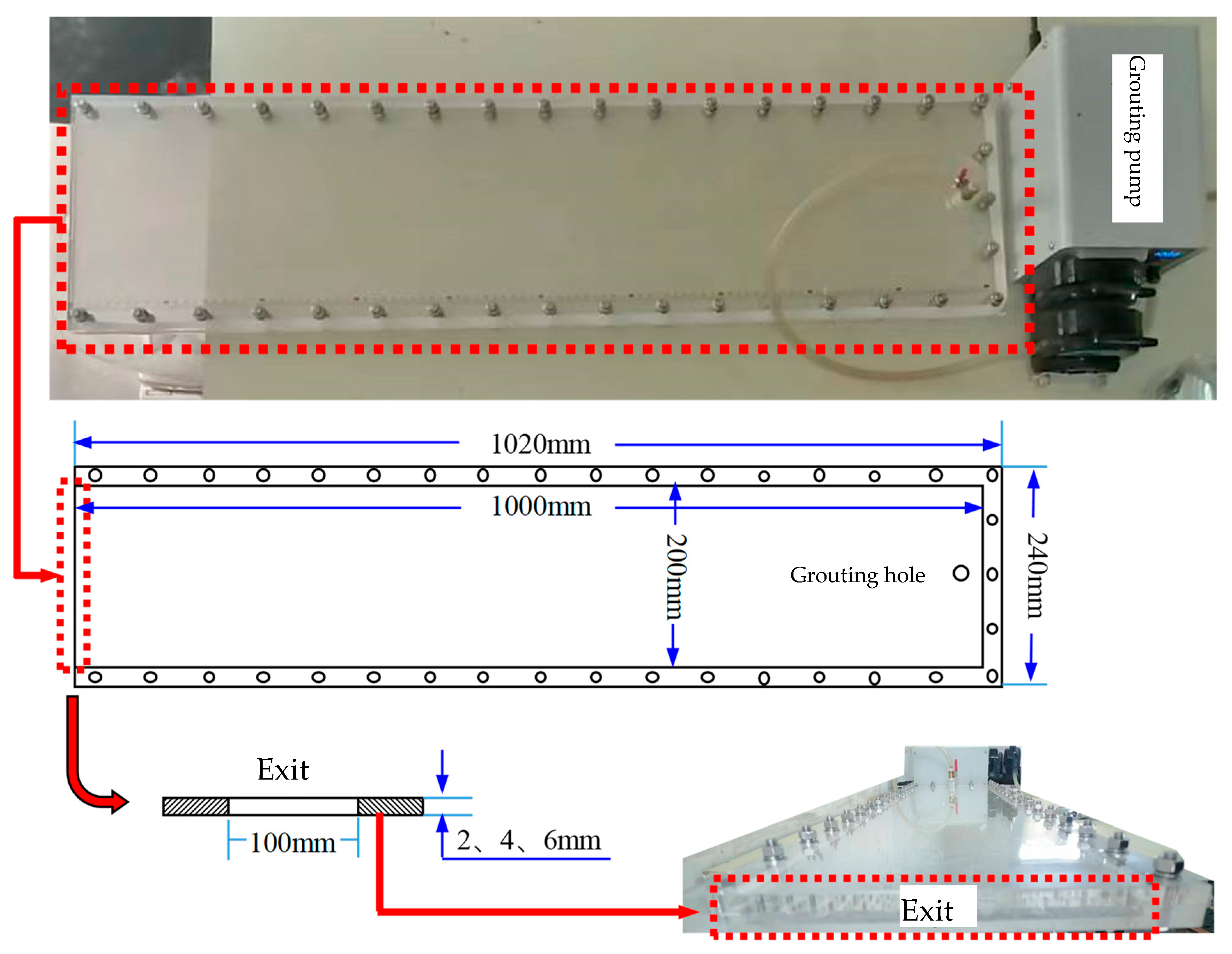
3.1. Test Methods

To test the expansion characteristics of SAP materials with different particle sizes in water and fly ash slurry, nine SAP granular materials with different particle sizes (5 mesh, 10 mesh, 20 mesh, 30 mesh, 40 mesh, 50 mesh, 60 mesh, 70 mesh, and 80 mesh) were selected as the experimental samples by sieving through square-hole sieves with different mesh sizes. The colloidal mass ratio (the ratio of the mass of the SAP material after water absorption to the mass of the original SAP dry material, which is a key indicator of the ability of SAP to absorb water), colloidal volume ratio (the ratio of the volume of SAP material after water absorption and expansion to the original volume, which is a key parameter for measuring the expansion ability of SAP material), and the fluidity properties in water and fly ash slurry were measured simultaneously for SAP material with different particle sizes. The actual photographs of the experimental materials for each particle size are shown in Figure 2.
In this experiment, 90 specially designed gauze bags were used as carriers, each containing one of the nine particle sizes of the SAP material. These gauze bags were fully immersed in water to observe and measure the change in the SAP material mass over time. To reduce the experimental error, the 90-mesh gauze bag was immersed in water for 5 min and the mass of the fully immersed gauze bag was weighed. In the experiment, 1 g of SAP materials with different particle sizes was weighed and added to a gauze bag, and the bag was placed in a beaker with 600 mL of water after tying the bag tightly with a string, ensuring that the gauze bag containing the SAP material was completely immersed in water. The gauze bag was removed from the beaker every 10 min during the experiment to monitor and control water absorption accurately. The total mass of the SAP materials and the gauze bag were weighed, and the total mass of the gauze bag after full immersion in water was subtracted. After full immersion in water, the colloidal mass ratio of the SAP materials with different particle sizes over time was measured. Simultaneously, 100 mL of water was measured into a graduated cylinder, and 1 g of SAP material was added. Every 10 s, the expansion of SAP particles was observed as they absorbed water and formed a gel-like colloid, and the volume of the precipitated SAP colloid in the cylinder was recorded. This volume measurement is considered to represent the SAP water absorption colloid volume ratio, with the denser SAP colloid settling at the bottom. In the calculation of the colloid volume ratio, the initial volume of 1 g of SAP was set to 1 cm3 for reference.

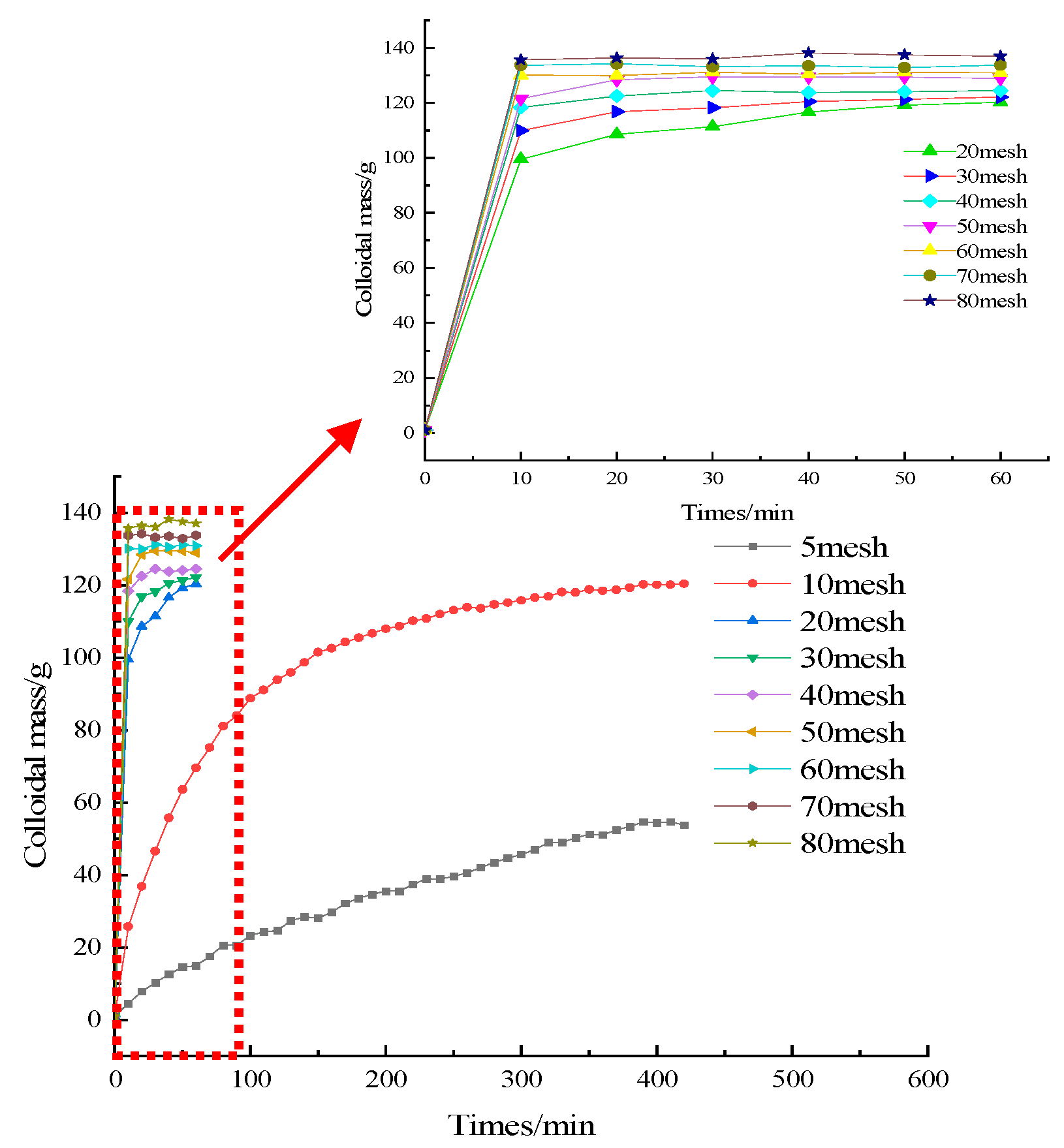
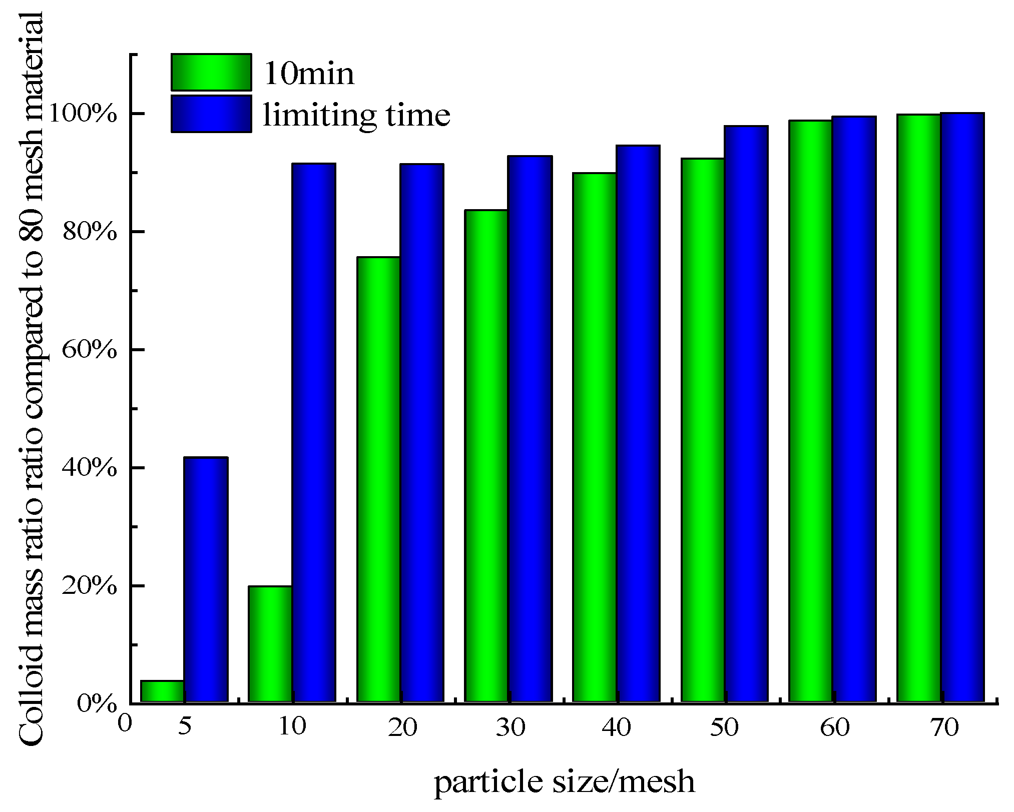
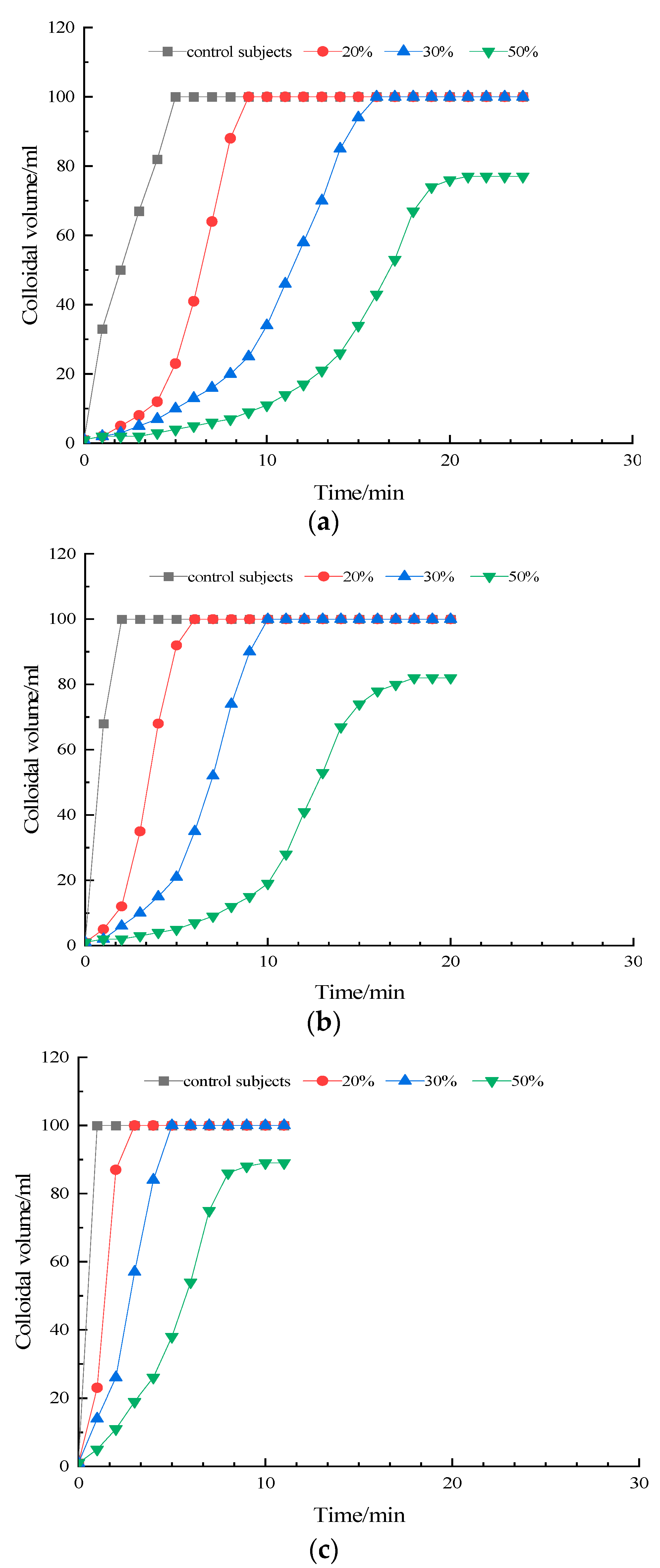
3.2. Expansion Characteristics

During the experiment, it was found that the colloidal mass ratio of the SAP materials with different particle sizes in water exhibited the same changes and significant segmented expansion. Moreover, as the particle size of the SAP materials decreased, the segmented expansion effect diminished. The experimental data for the SAP materials across each particle size condition revealed that the SAP with a particle size of 80 mesh reached its maximum colloidal mass ratio within 10 min of water absorption. At this point, the colloidal mass stabilized at 131.8 g. Figure 3 illustrates the colloidal mass ratio at 10 min and the time taken to reach the maximum colloidal mass ratio for SAP materials with various particle sizes. These data indicate the effect of SAP particle size on the resulting colloidal mass ratio.
As shown in Figure 4, the colloidal mass ratios of the SAP materials with a particle size of 5 mesh, 10 mesh, 20 mesh, 30 mesh, 40 mesh, 50 mesh, 60 mesh, and 70 mesh in water for 10 min were 3.5%, 19.6%, 75.5%, 83.5%, 89.8%, 92.3%, 98.7%, and 99.8%, respectively, of that of SAP materials with a particle size of 80 mesh. The limiting colloidal mass ratios of the SAP materials of the above-mentioned particle sizes were 41.5%, 91.4%, 91.3%, 92.7%, 94.5%, 97.8%, 99.4%, and 100.0% of the colloidal mass ratios of the SAP materials with a particle size of 80 mesh, respectively. The above results reveal that the particle size on the SAP material’s colloidal mass ratio is mainly observed in the range of 0–10 min, and the final colloidal mass ratios for SAP materials across different particle sizes exhibit minimal variation (except for the material with a particle size of 5 mesh). For the SAP materials with particle sizes of 10–80 mesh, smaller particle sizes exhibit stronger water absorption capacity under the same time conditions, resulting in a higher colloidal mass ratio upon water absorption and expansion.
From the experimental results shown in Figure 5, the water absorption and expansion process of the SAP material exhibits a linear growth trend in colloid volume changes. The variation in water absorption and expansion for SAP materials with different particle sizes lies in the differing rates of water absorption. With the particle size of 20 mesh, the expansion of colloidal volume reached its maximum within 280 s; with the particle size of 40 mesh, the expansion of colloidal volume reached its maximum within 100 s; with the particle size of 60 mesh, the expansion of colloidal volume reached its maximum within 50 s; with the particle size of 40 mesh, the expansion of colloidal volume reached its maximum within 100 s; with the particle size of 60 mesh, the expansion of colloidal volume reached its maximum within 50 s. Therefore, under identical water immersion conditions, SAP materials with smaller particle size absorbed water more quickly, resulting in a larger volume of swollen colloid produced within a shorter period. This phenomenon occurred because the thickness of the SAP material with a smaller particle size was reduced from the outer wall to the inner core, resulting in a limited capacity for water absorption and expansion. Simultaneously, because the area in contact with water was relatively larger, the particle size of the SAP material could be adjusted to control the time to reach the limiting colloidal volume and regulate the material’s expansion time.

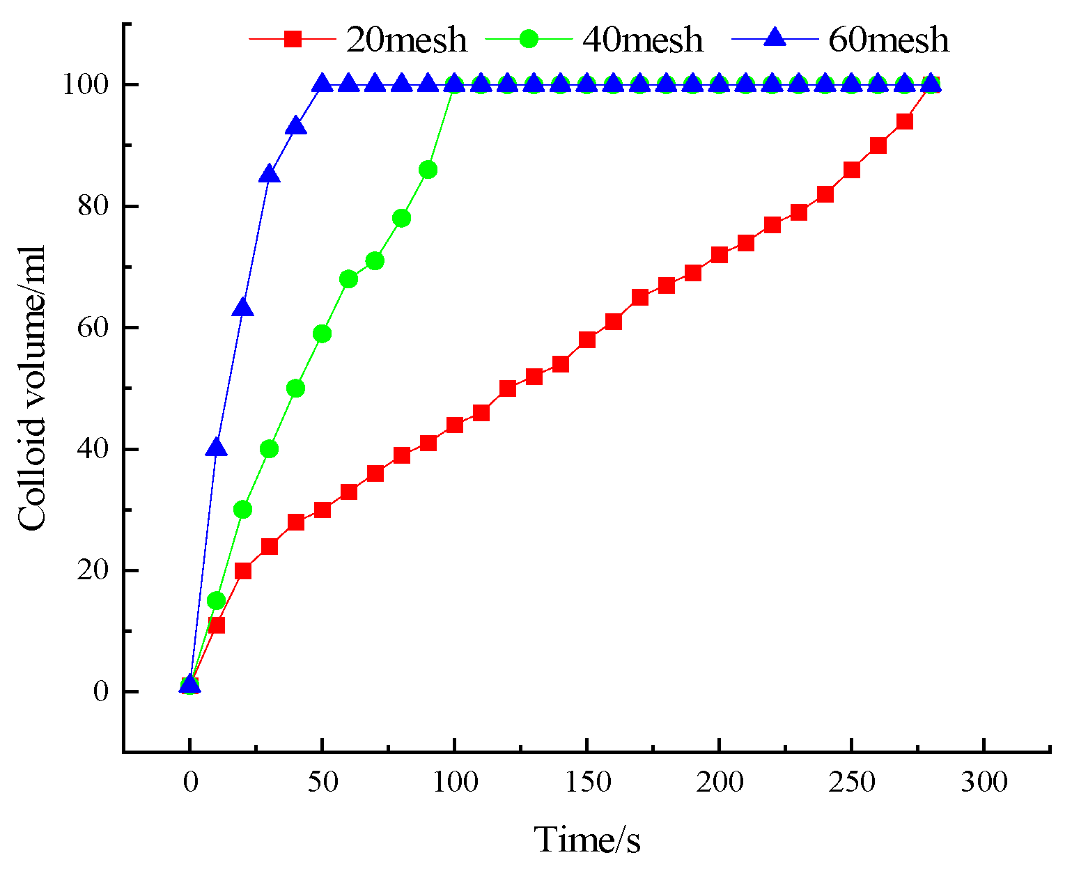
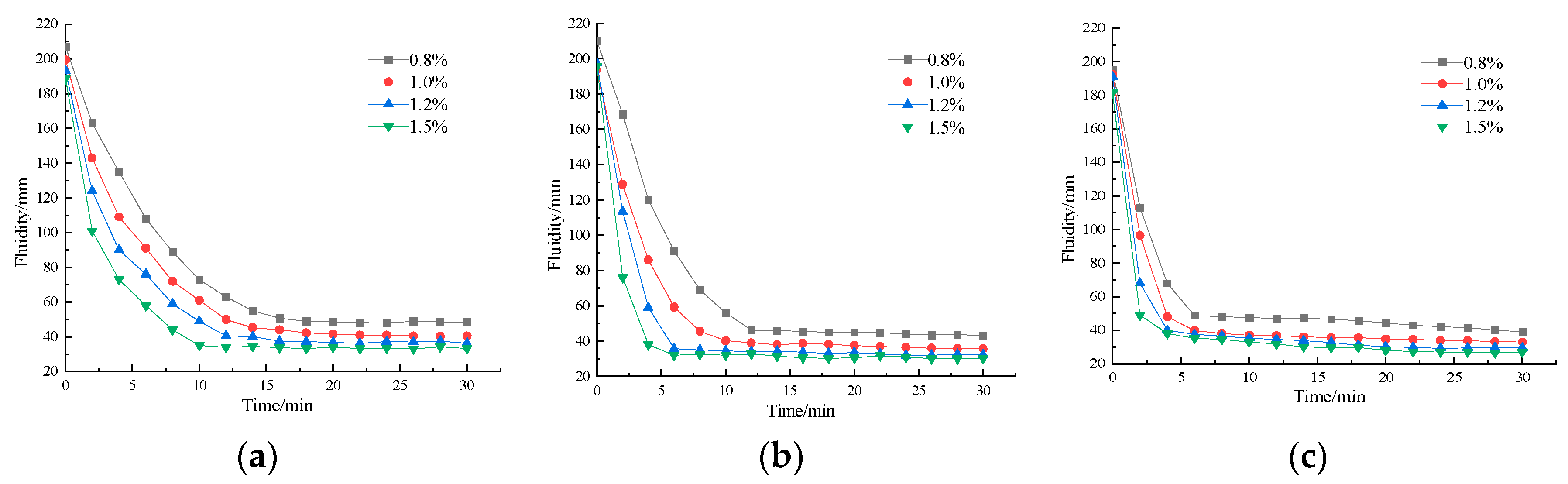
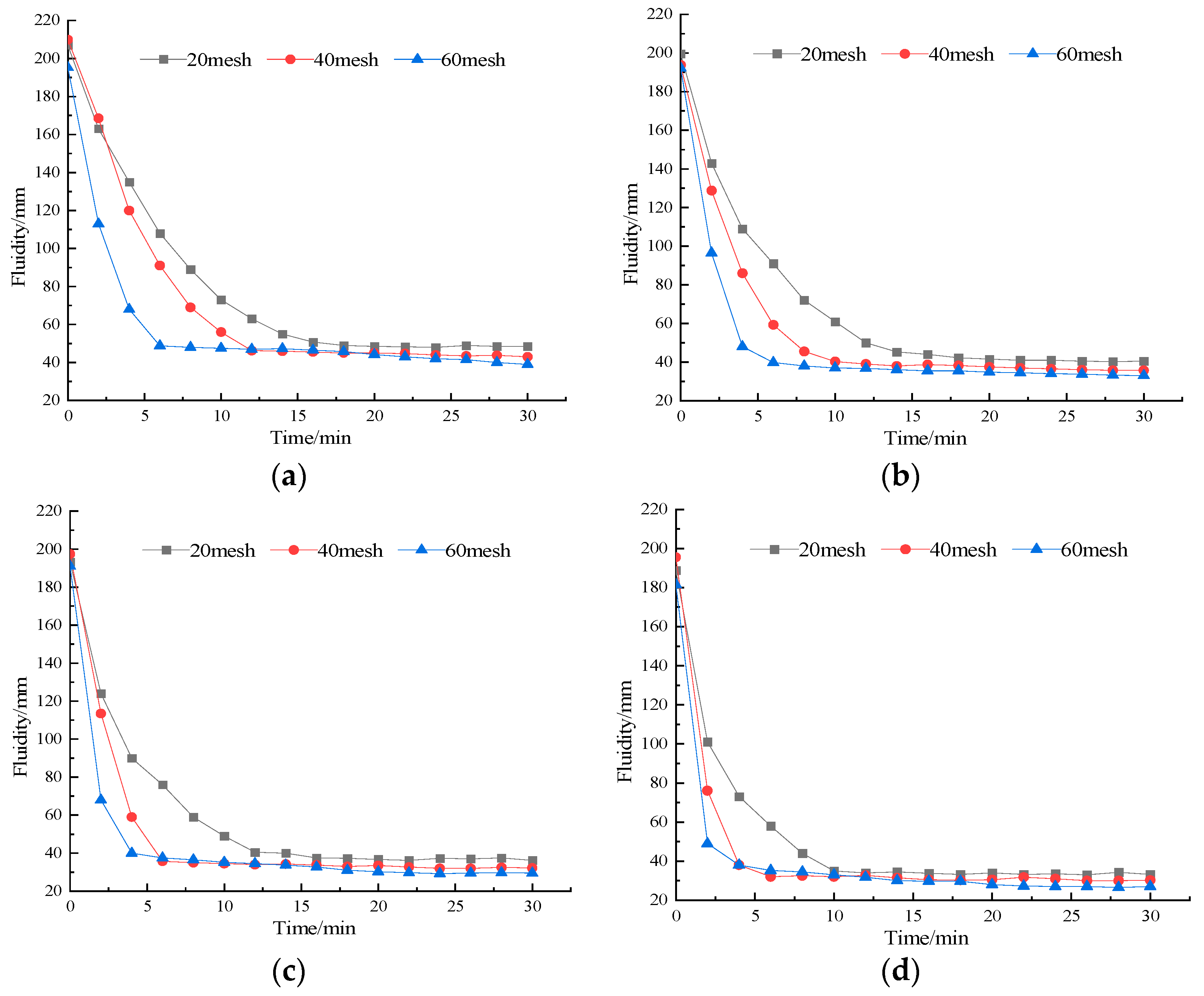
3.3. Flow Characteristics

The mobility experiment investigated the behavior of the material over time in the slurry to assess the flow characteristics after incorporating SAP materials with different doping ratios. This evaluation aimed to ensure that the slurry maintained a certain degree of mobility during the pumping process, and that it loses its mobility when reaching a fracture, allowing for complete expansion and effective fracture sealing.
The experimental results in Figure 6a reveal that, when the material particle size was 20 mesh, and the mixing ratio in water was set to 0.8%, 1.0%, 1.2%, and 1.5%, respectively, the stability times of the slurry flow were 16 min, 14 min, 12 min, and 10 min. At this time, the SAP material in water had reached the state of saturated water absorption in the corresponding time mentioned above. Therefore, as the SAP mixing ratio in water increased, the water loss efficiency of the slurry improved, resulting in the reduction in residual free water within the slurry and subsequently impairing its flow characteristics. For the SAP materials with the particle sizes of 40 mesh and 60 mesh, the flow behavior when mixed with water followed the same pattern observed in the 20-mesh slurry.
Figure 7 shows the effects of SAP materials with different particle sizes at the same mixing ratio. As can be seen, under identical conditions, the flow behavior of the SAP in water is significantly influenced by the particle size. Specifically, a smaller particle size leads to a more rapid decrease in flow. Therefore, as the particle size of the SAP material decreases, the slurry loses its flow characteristics more quickly after SAP is added to water.
The changes in the fluidity of SAP material mixed with fly ash slurry are illustrated in Figure 8. With the particle size of 20 mesh, the mixing ratios in the fly ash slurry were 1.0% and 1.5%, resulting in slurry fluidity stabilization at 18 min and 14 min, respectively. With the particle size of 40 mesh, the mixing ratios in the fly ash slurry were 1.0% and 1.5%, and the slurry fluidity stabilized at 14 min and 12 min, respectively. With a particle size of 60 mesh, the mixing ratios in the fly ash slurry were 1.0% and 1.5%, respectively, and the slurry fluidity stabilized at 8 min and 6 min, respectively. Therefore, a larger mixing ratio of SAP material in the fly ash slurry results in a larger reduction in the slurry’s flow rate.
The flow degree of SAP material added in fly ash slurry was approximately 80 mm. After the test had been carried out for 30 min, the flow degree of slurry was still floating at approximately 45 mm, indicating that the SAP material in the fly ash slurry did not absorb water as effectively as it did in pure water. This resulted in a more restricted decrease in flowability, although a downward trend was still noted. The addition of SAP materials at a mixing ratio of 1.0%–1.5% to the fly ash slurry had a minimal effect on slurry flow. The reason for this may be the smaller size of fly ash particles, which remained suspended in the slurry and tightly adhered to the surface of the SAP material. This adherence restricted the contact area between the SAP and water, ultimately impairing the water-absorbing capacity of the SAP. Additionally, after the occurrence of water secretion in fly ash, the fly ash particles were deposited to the bottom of the slurry, and the secretion water was in the upper part of the deposited slurry. This secretion water can be classified as free water, while the water in the slurry can be regarded as bound water. Therefore, the amount of free water in the fly ash slurry was very limited, the amount of free water absorbed by the SAP was small, and the material failed to reach its ultimate expansion level.

4. Preparation and Properties of Sealing Material
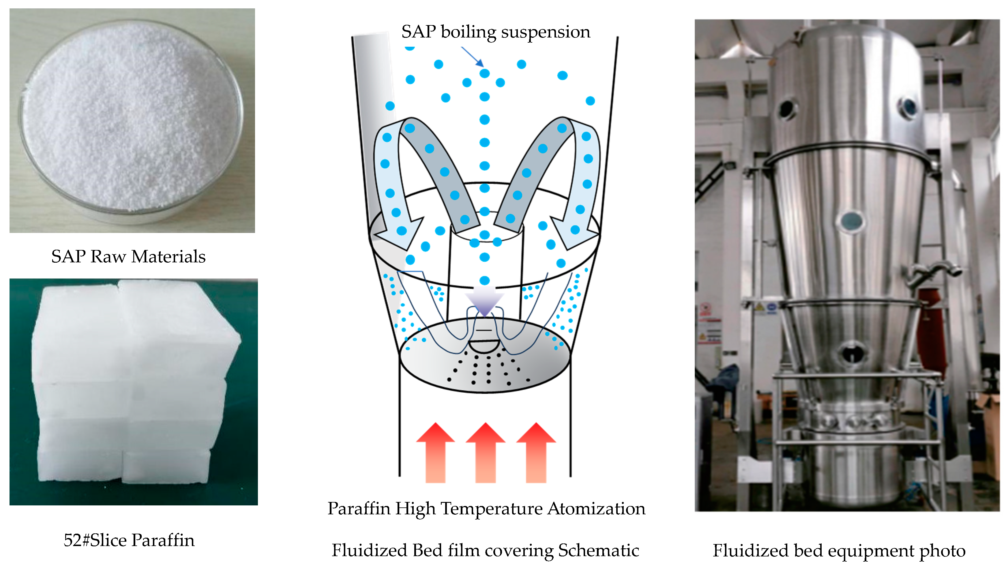
4.1. Preparation

Although SAP material has the ability of fast sealing, in overburden isolation grouting filling engineering, SAP can only enter the filling area through grouting drilling and subsequently spread to the fracture channel. Additionally, SAP expands rapidly upon encountering water. In actual filling projects, SAP swells completely before entering the fracture channel, preventing the swollen colloid from penetrating the fractures where the slurry is being applied. Consequently, the SAP material becomes ineffective at sealing large open fractures. Moreover, the bulkiness of the colloid that accumulates at the bottom of the borehole significantly hinders the diffusion capacity of the filling slurry, which may result in adverse outcomes, such as the sealing of the filled borehole. Therefore, it is not possible to add SAP directly to the filling slurry for fracture sealing.
To solve the problem of the rapid expansion of SAP upon contact with water, which prevents the direct use of SAP for fracture sealing, this study used the air suspension method, which utilizes fluidized bed film coating technology, to apply a protective layer to SAP particles, thereby creating a sealing capsule designed for managing the slurry used in coal mine overlay isolation grouting. This external film coating serves as a shell membrane that isolates the SAP material from direct contact with water during the initial mixing with the slurry, ensuring that the SAP remains protected until needed. However, this protective film is not permanent; when the sealing capsule containing the SAP material reaches the slurry diffusion channel in the fracture, the protective shell membrane ruptures. This allows the SAP to rapidly expand upon contact with water, achieving the initial sealing of the slurry as intended.
Figure 9 shows the laminating process, where the SAP material particles (the capsule core) are suspended in the air. A wall material solution was sprayed into the fluidized bed, causing the capsule core to roll in a suspended state. As the wall solution was sprayed onto the surface of the particles, the solvent evaporated, allowing the wall material to adhere to the particles. Through a continuous cycle of upward and downward motion, a protective layer gradually formed around the capsule core. This was followed by a drying phase, resulting in the formation of microcapsules.
Some of the SAP overlay requirements are as follows:
(a)
SAP raw material with core sizes of 20, 40, and 60 mesh;
(b)
The ratio of the coated wall material to the capsule material is 20%, 30%, and 50%.
To measure the percentage of SAP in the sealing material in relation to the content of the paraffin wall material, the “overlay ratio” is defined as follows:
F = lm/sm
where f is the overlay ratio, lm is the mass of paraffin (g), and sm is the mass of SAP (g).

4.2. Properties

To investigate the effect of particle size and overlay ratio on the delay effect, expansion capacity, and fluidity performance of the SAP sealing material, this study designed the plugging material capsule cores using commonly used granular filling materials for grout filling. The capsule cores consisted of pure SAP material with particle sizes of 20 mesh, 40 mesh, and 60 mesh. The wall material used was #52 sliced paraffin wax (density of 0.88–0.91 g/cm3, melting point of 52 °C) with overlay ratios of 20%, 30%, and 50%. Additionally, a control group consisting of pure SAP material with the same particle size as the sealing material was included for comparison. The film cover ratio was 20%, 30%, and 50%, respectively. The control group was designed to be pure SAP material with the same particle size as that of the sealing material. The results of the two experiments were compared to validate the feasibility of the SAP sealing material in grouting and leakage sealing after film covering.
In the overburden isolation grouting and filling project, the fracture aperture of the filling is small, and the practice shows that the appropriate particle size of the slurry should be less than 0.2 mm. If the particle size is too small, it is obvious that the leakage fracture cannot be blocked. If the particle size is too large, there is a risk of blockage in the grouting channel. That is why particle sizes of 20 mesh, 40 mesh, and 60 mesh were selected in this paper.
Regarding the film covering ratio, it is mainly determined by laboratory experiments. If the film covering ratio is too small, the expansion will be very fast, and the purpose of delay expansion cannot be achieved. In this case, there is a risk of blocking for the grouting channel in the engineering. If the film ratio is too large, the expansion time will be too long; the sealing material will not expand after flowing into the leakage fracture, and the leakage cannot be sealed. According to the experiment, the appropriate film ratios were determined to be 20%, 30%, and 50%.
The expansion rate of pure SAP material is approximately 100–150 times its original mass. Therefore, in the expansion rate experiments, the quantity of water should be controlled to be at least equal to or greater than 100 times the mass of SAP dry material to ensure sufficient conditions for complete expansion. To conduct the swelling test, 100 g of tap water was prepared and placed in each of nine 100 mL measuring cylinders. Each cylinder received a different sealing material, added at a 1:100 ratio (1 g of SAP material per 100 g of water). The materials varied by mesh size and overlay ratio as follows: 1 g of 20 mesh (20%), 20 mesh (30%), 20 mesh (50%), 40 mesh (20%), 40 mesh (30%), 40 mesh (50%), 60 mesh (20%), 60 mesh (30%), and 60 mesh (50%). The swelling of each material was observed and recorded continuously during the testing process, and the swelling status of the material was recorded at 1 min intervals until the material had fully expanded. Samples of sealing material with particle sizes of 20 mesh, 40 mesh, and 60 mesh at overlay ratios of 20%, 30%, and 50% were tested. Throughout the experiment, the expansion of each sample in water was observed continuously and recorded at 1 min intervals. This process continued until each sample had absorbed water to its maximum expansion limit, and the slurry had fully solidified, at which point the experiment was concluded.
The pure SAP material started to expand rapidly upon contact with water, and expanded completely within only 1 min. Additionally, after contact with water, the SAP plugging material did not immediately undergo water-absorbing expansion, but was instead suspended in the water surface. The main reason for this behavior is that the outer surface of the SAP material was coated with low-density paraffin wax. When the sealing material was submerged in water, the paraffin wax layer encountered water first, preventing the underlying SAP material from immediate water exposure and subsequent absorption and expansion. This delay in water interaction distinguishes the coated SAP from uncoated, pure SAP, which absorbs water and expands upon initial contact. However, the sealing material did not maintain the state of non-expansion indefinitely. Soon, the dense SAP small particles continued to expand and sink. After 5 min, some of the expanded material settled at the bottom of the beaker, while a portion of the sealing material remained unexpanded at the water’s surface. After 15 min, the sealing material had essentially expanded completely. The reason for this behavior is that, unlike the pure SAP material, the sealing material was covered by paraffin wax and the tightness of the package was insufficient, which led to the rapid expansion of the SAP material in the capsule upon exposure to water and the cracking of the wax wall. Eventually, the wax material was suspended in the water, and the expanded material precipitated to the bottom of the liquid system.
As shown in Figure 10, by comparing the expansion of pure SAP material with the 20-mesh (20%, 30%, 50%), 40-mesh (20%, 30%, 50%), and 60-mesh (20%, 30%, 50%) SAP sealing material, it can be found that, under the same material particle size, the film cover ratio is the key factor influencing the expansion rate. In other words, a higher film cover ratio of SAP materials with the same particle size leads to a better delayed-expansion effect, resulting in an extended time for the material to reach its maximum expansion limit. Additionally, with the same film cover ratio, larger particle sizes exhibit greater time-delayed expansion ability in the developed sealing material compared with the pure SAP material at the same particle size.
The experimental results in Figure 11 indicate that, with overlay ratios of 20%, 30%, and 50% and water mixing ratios of 1.0% or 1.5%, the change in slurry fluidity follows a similar trend across different particle sizes. However, by comparing the 60-mesh SAP material with the 20-mesh and 40-mesh sealing materials with different film cover ratios and dosages, it can be found that the 60-mesh SAP material initially absorbed and swelled more rapidly in water, resulting in an immediate and sharp decrease in slurry fluidity. Subsequently, the slurry was fully swollen after 5 min and almost completely lost its fluidity. The flow of the 20-mesh and 40-mesh sealing materials with different film cover ratios and dosages tended to stabilize with time.
In summary, the results for the flowability of sealing materials with different particle sizes and film cover ratios in water and fly ash slurry reveal that a higher film cover ratio results in better slurry flowability after the sealing materials are doped into the water or fly ash slurry. Additionally, the slurry’s flowability is continuously weakened as the doping ratio of the sealing materials increases, while the film cover ratio of the sealing materials remains the same.

5. Sealing Effectiveness

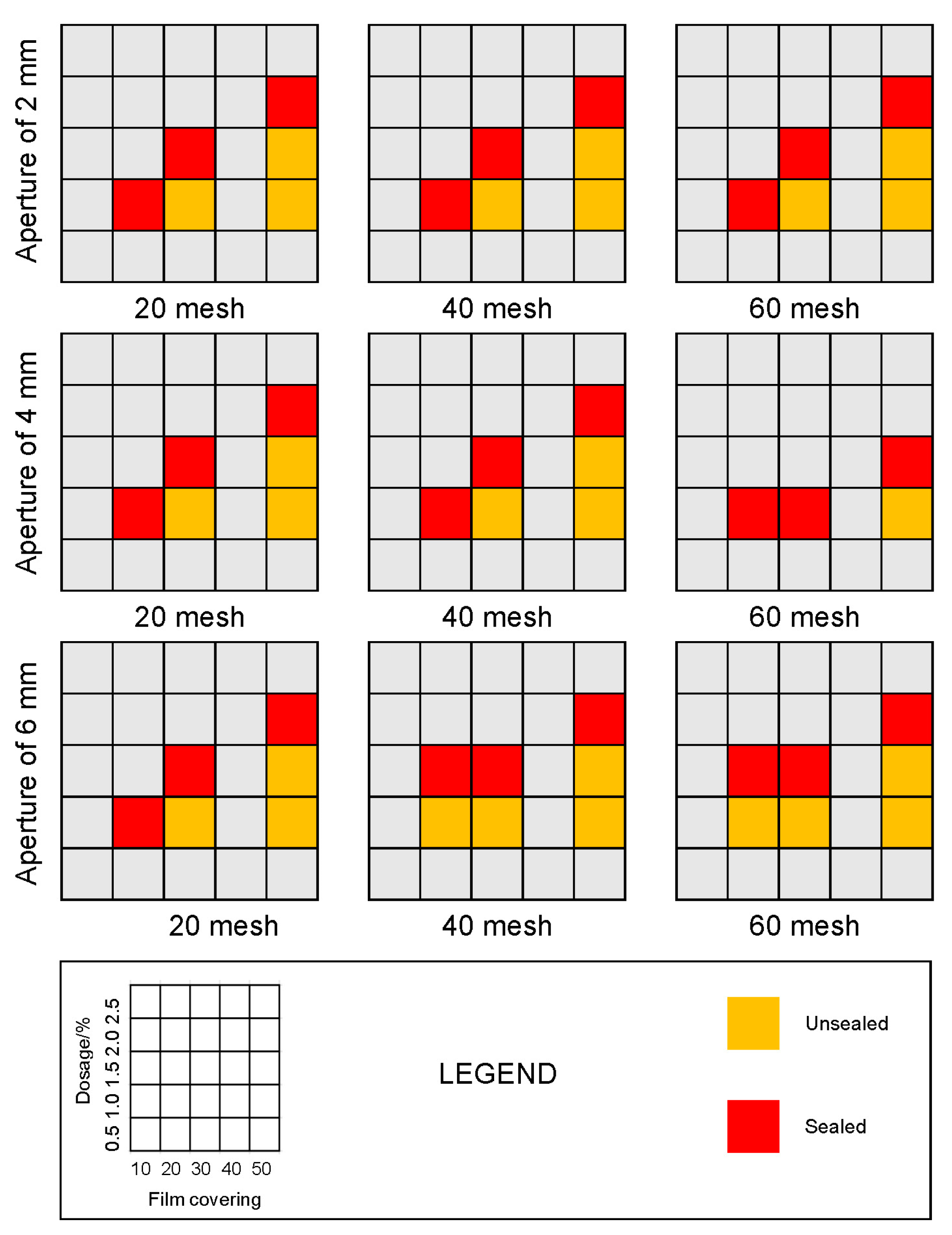
5.1. Experimental Design

To measure the sealing condition of the sealing material in the fracture, a fracture grouting sealing test model was designed to simulate the grouting sealing process under different fracture opening conditions and evaluate the sealing effect of the sealing material. The main body of the model system had a length of 1020 mm and width of 240 mm and consisted of two rectangular acrylic boards with equal size and thickness of 15 mm. Grooves were ground into the top surface of the lower plate using a sanding machine, creating a rough texture to simulate the irregular nature of stratum slurry cracks. These grooves were hollowed to varying depths to represent fractures with different degrees of openness. In the bottom of the three identical lower templates, 2, 4, and 6 mm slots were hollowed out, sealing tape was glued to the edge of the upper plate, and holes were created at equal intervals between the edges of the upper and lower plates. Additionally, bolts were used to connect the upper and lower rectangular acrylic plates to seal the sealing tape, ensuring that the fracture simulation was airtight. Grouting holes were reserved at the upper boundary of the upper plate to simulate grouting injection. The internal width of the three different apertures of the fracture was 200 mm, and the length of all fractures was 1000 mm (Figure 12). The main body of the experimental device was a three-sided seal, with a slurry outlet on the left side as a channel for the slurry running through the fracture. A measuring cup for recovering the leaking slurry was placed at the outlet on the left side, and an electronic scale was placed under the measuring cup to measure the mass of the slurry leakage continuously during the grouting process. The leakage rate, K, is used to describe fracture sealing, and is defined as follows:
K = Ml/Tl
where Ml is the mass of slurry that was lost (g), and Tl is the time taken to lose the mass of Ml (min).
Grout-filled fracture sealing experiments were carried out using the experimental setup shown in Figure 12. The SAP sealing materials used in the experiment had particle sizes of 20 mesh, 40 mesh, and 60 mesh, with film cover ratios of 20%, 30%, and 50%, respectively. To measure the delayed expansion sealing effect of the sealing material, before using the sealing material for leakage plugging, pure water should be used to carry out comparative experiments to ensure that the sealing material used in the experiments fully expands as it flows to the exit in the experimental setup. In the experimental process, the grouting pump was used with a flow rate of 200 mL/min, and the experimental fissure aperture was set to 2 mm, 4 mm, and 6 mm; the corresponding volumes of the fracture cavities were 400 cm3, 800 cm3, and 1200 cm3. The theoretical flow time for the slurry to diffuse from the grouting holes to the slurry outlet of the fracture within the fracture cavity was 2 min, 4 min, and 6 min, respectively. The expansion time of the sealing material was obtained from a previous experimental study. Table 1 lists the time and mixing time required for the SAP sealing material with different particle sizes and overlay ratios to reach full expansion when the fracture apertures were 2 mm, 4 mm, and 6 mm.

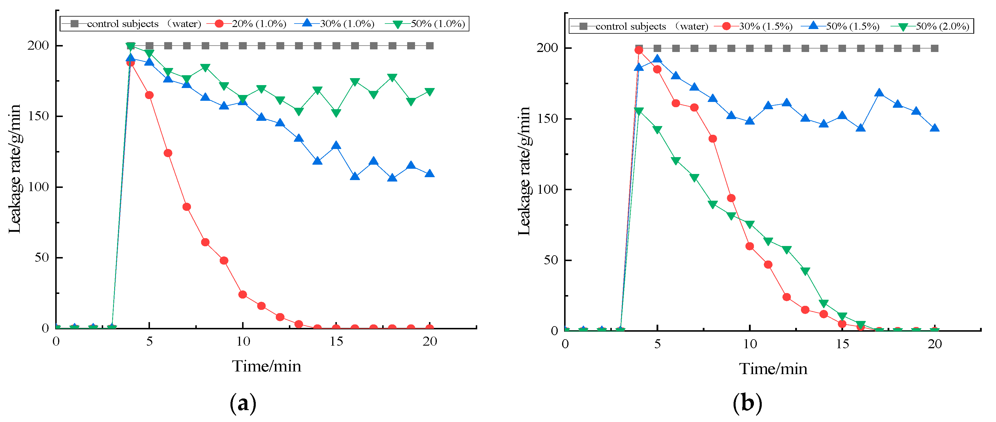
5.2. Role of SAP Materials

The sealing effect under different fracture openings, different coating ratios, different sealing material dossing ratios and other parameters is shown in Figure 13.
Considering the fracture opening of 2 mm as an example, sealing materials with a particle size of 20 mesh, 40 mesh, and 60 mesh and overlay ratios of 20%, 30%, and 50%, respectively, were used for sealing. The mixing ratios of these three types of sealing materials were 1.0%, 1.5%, and 2.0%. Initially, the 20-mesh sealing material with a mixing ratio of 1.0% was applied to seal the 2 mm fracture. The experimental results shown in Figure 14 indicate that only the sealing material with a particle size of 20 mesh and overlay ratio of 20% achieved fracture sealing, with complete sealing achieved within 20 min. The leakage amount at the outlet was 0 g/min at 0–3 min. Subsequently, the leakage amount at the outlet increased from 0 g/min to 199 g/min at 3–4 min. Then, the leakage amount decreased continuously, ultimately reaching 169 g/min at 10 min. Then, the leakage amount started to decrease abruptly until the leakage amount at the outlet was 0 g/min at 20 min to complete fracture sealing. For the 20-mesh sealing material with the film cover ratios of 30% and 50%, significant leakage persisted at the exit during the grouting process, preventing complete fracture sealing. However, when the mixing ratio of the 20-mesh material with a film cover ratio of 30% was increased from 1.0% to 1.5%, effective sealing of the slurry fracture was achieved within 14 min. The sealing material with a particle size of 20 mesh and film cover ratio of 50% required an increase in the mixing ratio from 1.0% to 1.5%, but still failed to fully seal the slurry leakage fracture. However, when the mixing ratio was increased to 2.0%, effective sealing of the fracture was achieved within 15 min.
The results (Figure 15) obtained by experiments using a sealing material with a particle size of 40 mesh and film cover ratios of 20%, 30%, and 50% on a 2 mm fracture reveal that the 40-mesh material with 20% film cover achieved complete fracture sealing at the mixing ratio of 1.0% within 14 min. However, for the 40-mesh materials with 30% and 50% film cover, significant leakage persisted throughout the grouting process, preventing effective fracture sealing. During the grouting process, substantial leakage occurred, preventing successful fracture sealing. When the sealing material with a particle size of 40 mesh and film cover ratio of 30% was used at the mixing ratio of 1.0%–1.5%, effective fracture sealing was achieved within a sealing time of 17 min. The sealing material with a particle size of 40 mesh and film cover ratio of 50% did not achieve effective fracture sealing at the mixing ratios of 1.0%–1.5%. However, increasing the mixing ratio to 2.0% resulted in successful slurry fracture sealing, with a sealing time of 17 min.
The experimental results for sealing a 2 mm fracture using sealing material with a particle size of 60 mesh and film cover ratios of 20%, 30%, and 50% are shown in Figure 16.
The sealing materials with a particle size of 60 mesh and film cover ratios of 20% and 30% achieved successful fracture sealing at the mixing ratio of 1.0%, with sealing times of 11 min and 14 min, respectively. However, the sealing material with a particle size of 60 mesh and film cover ratio of 50% consistently exhibited significant leakage at the outlet during the grouting process, resulting in failure to complete fracture sealing. However, by increasing the mixing ratio of the sealing material with a particle size of 60 mesh and film cover ratio of 50% from 1.0% to 1.5%, successful sealing of the running slurry cracks was achieved, within a sealing time of 13 min.

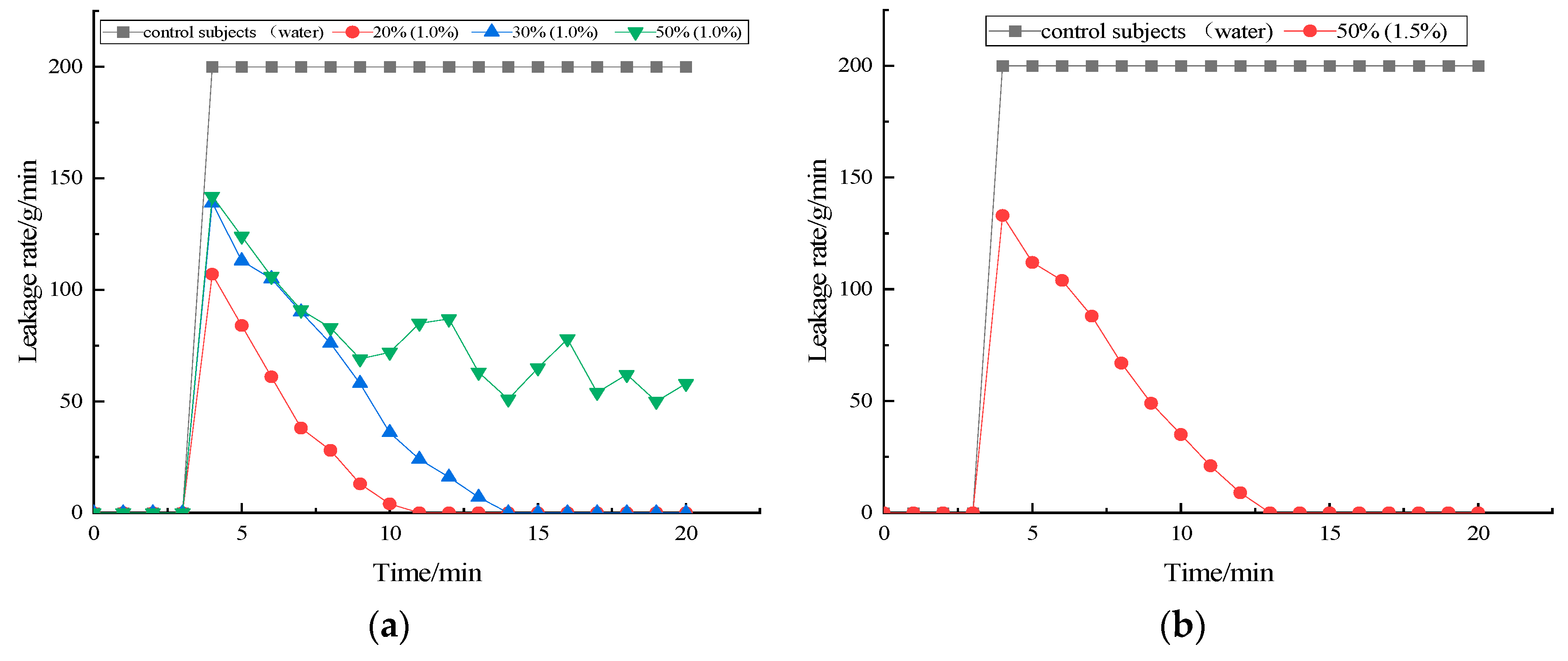
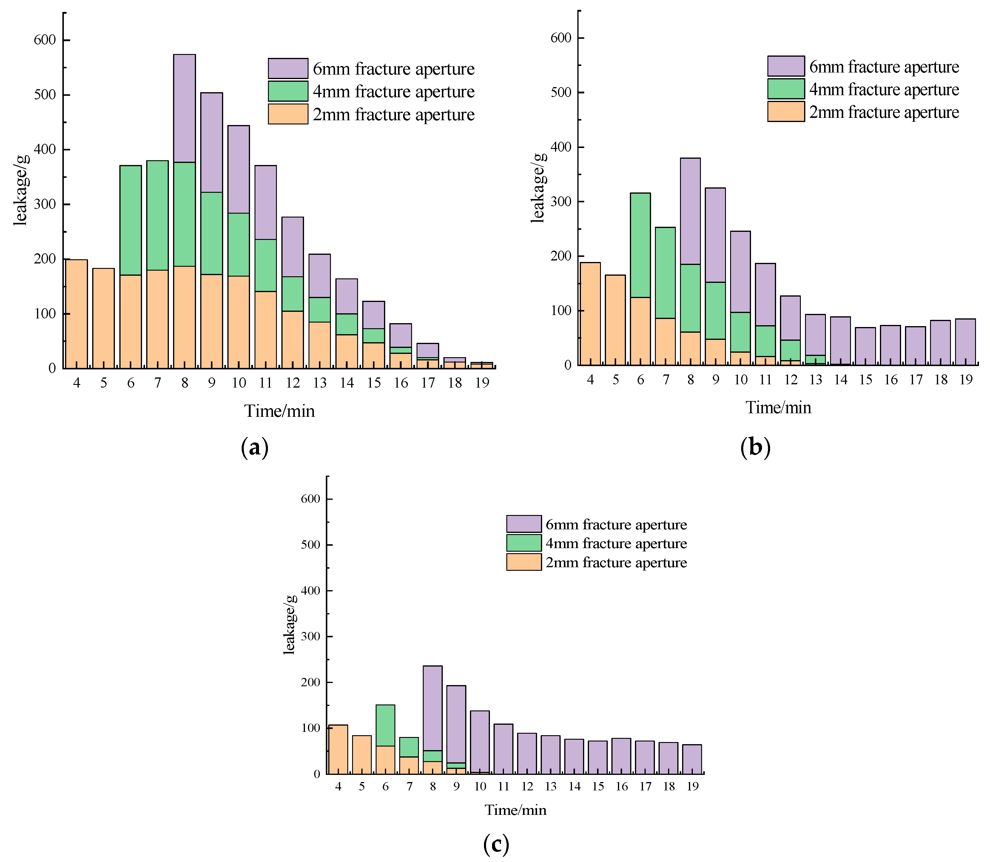
5.3. Role of Fracture Aperture

In the experimental study of sealing effectiveness across different fracture apertures, this study obtained a series of experimental results that highlight significant differences in the performance of sealing materials based on varying fracture sizes.
As shown in Figure 17, the comparison among the leakage amount of the SAP sealing materials with the particle sizes of 20 mesh, 40 mesh, and 60 mesh at different fracture apertures reveals that a smaller particle size results in a lower leakage amount of SAP sealing materials at the early stage of the fracture, when the fracture opening is small. This is because particles with larger size in the smaller fracture openings can more easily form an effective physical barrier and are better able to interlock and form a bridge, reducing the fluid through the fracture channel, thereby better controlling the amount of leakage. With the gradual increase in the crack opening, the SAP sealing material with a particle size of 20 mesh exhibited unique advantages. A smaller particle size can penetrate the finer sections of the fracture, allowing for more effective filling and the formation of a denser sealing layer beneath larger fracture openings. This results in reduced leakage and a superior sealing effect compared to materials with a particle size of 20 mesh.
The different particle sizes of SAP sealing materials have different advantages and disadvantages under different crack apertures. The sealing material with a particle size of 20 mesh performs better under small crack apertures, while the 60-mesh material exhibits better sealing ability under larger crack apertures. This result provides an important basis for the reasonable selection of the particle size of SAP sealing material according to the crack opening in different engineering scenarios.
In summary, when the fracture opening did not exceed 4 mm, the sealing materials with a particle size of 20 mesh, 40 mesh, and 60 mesh, and a film ratio of 20%, were able to complete fracture sealing at a mixing ratio of 1.0%. For sealing materials with film ratios of 30% and 50%, the particle size of the sealing material must be increased, and the mixing ratio must be adjusted to 1.5–2.0% to effectively seal fractures below 4 mm. When the crack opening degree ranges from 4 to 6 mm, the mixing ratio of the sealing material with film cover ratios of 20% and 30% should not be lower than 1.5%, while the mixing ratio of the sealing material with a 50% film cover ratio should not be lower than 2.0% to achieve effective sealing. Therefore, the film cover ratio is the main influencing factor. A higher paraffin film ratio results in lower SAP content released in the sealing material after doping into water. Hence, the sealing material mixing ratio must be improved to realize crack sealing. Conversely, under the same mixing ratio, the sealing material demonstrates improved leakage control performance.

6. Conclusions

Grouting technology is an important method for underground reinforcement. However, unexpected fractures may lead to substantial grout leakage, resulting in unsatisfactory grouting. This paper proposes a new sealing method for coal mine overburden isolated grouting engineering. By exploiting the high expansion and water absorption properties of SAP, a time-delayed sealing material was prepared using paraffin-coated SAP particles to achieve leakage sealing. The swelling capacity and fluidity performance of the material were tested. To assess the material’s fracture sealing capability, a fracture sealing model was designed and investigated experimentally.
The swelling colloid mass ratio, colloid volume ratio, and flowability of the SAP material mixed with water and fly ash slurry were tested, respectively. The results revealed that the SAP materials with a smaller particle size absorbed water faster, resulting in the larger mass-to-volume ratio of the colloid. While the mixture of SAP and water lost flowability quickly, the flowability of the SAP and fly ash slurry mixture remained unaffected.
This study found that the expansion rate is controlled by the film cover ratio of SAP. A higher film cover ratio of SAP with the same particle size results in a longer expansion time and better flowability performance after being mixed with fly ash slurry. Overall, the flowability of the slurry decreased as the mixing amount of the sealing material increased.
The film cover ratio is a critical factor influencing the sealing effect. A high film cover ratio can overly restrict the expansion of the sealing material, compromising its sealing effectiveness, because an isolation layer is formed between the sealing material and the leakage fracture. Conversely, a low film cover ratio leads to fast expansion, which affects the sealing effect. The results obtained by the sealing simulation experiments revealed that fractures with apertures of less than 4 mm could be effectively sealed using a low mixing ratio (~1%) of the sealing material with different particle sizes. However, a larger mixing ratio of the sealing material was required for fractures with apertures of 4–6 mm. The findings of this study provide a theoretical basis for unexpected slurry leakage in coal mine overburden isolated grouting engineering.
Compared with the traditional natural sedimentation slow-sealing method and the chemical agent rapid-sealing method, the proposed sealing method in this paper is suitable for the plugging of leakage fractures under the conditions of large grouting flow and high pressure. It does not block the grouting channel, and can fix the leakage issue at a relatively short time, which ensures better grouting continuity and reduces the negative impact on the grouting effect. The paraffin and SAP materials used have no adverse impact on the environment because of low content, and the cost is low. It should be noted that this method may not be suitable for a long lag time of >15 min, since the delayed expansion time of the material has a limitation. It is likely that the expansion occurs before the material flow into the leakage fracture, resulting in the blockage of the grouting channel.

Author Contributions

Conceptualization, D.X. and J.L.; methodology, D.X.; formal analysis, X.N. and K.L.; investigation, X.N. and J.L.; resources, X.N.; data curation, X.N. and J.L.; writing—original draft preparation, D.X.; writing—review and editing, D.X. and K.L.; visualization, X.N. and K.L.; supervision, J.X.; funding acquisition, D.X. All authors have read and agreed to the published version of the manuscript.

Funding

This research is funded by the Natural Science Foundation of China (Grant No. 52374143).

Institutional Review Board Statement

Not applicable.

Informed Consent Statement

Not applicable.

Data Availability Statement

The data presented in this study are available on request from the corresponding author.

Conflicts of Interest

The authors declare that there are no conflicts of interest regarding the publication of this paper.

References

  1. Li, H.; Guo, G.; Zha, J.; Wang, T.; Chen, Y.; Yuan, Y.; Huo, W. A New Method of Regional Mining Subsidence Control for Sustainable Development in Coal Areas. Sustainability 2023, 15, 7100. [Google Scholar] [CrossRef]
  2. Xuan, D.; Li, J.; Zheng, K.; Xu, J. Experimental study of slurry flow in mining-induced fractures during longwall overburden grout injection. Geofluids 2020, 2020, 8877616. [Google Scholar] [CrossRef]
  3. Xuan, D.; Xu, J.; Zhu, W. Backfill mining practice in China coal mines. J. Mines Met. Fuels 2013, 61, 225–234. [Google Scholar]
  4. Li, S.; Yu, L.; Dan, Z.; Yin, T.; Chen, J. The Recent Progress China Has Made in Mining Method Transformation, Part I: Shrinkage Method Transformed into Backfilling Method. Appl. Sci. 2024, 14, 10033. [Google Scholar] [CrossRef]
  5. Li, S.; Xiang, Z.; Dan, Z.; Yin, T.; Chen, J. The Recent Progress China Has Made in Mining Method Transformation: Part II Sublevel Caving Method Transformed into Backfilling Method. Appl. Sci. 2024, 14, 9732. [Google Scholar] [CrossRef]
  6. Li, J.; Xuan, D.; Xu, J.; Dong, Z.; Wang, C. Compaction Response of Mining-Induced Rock Masses to Longwall Overburden Isolated Grouting. Minerals 2023, 13, 633. [Google Scholar] [CrossRef]
  7. Ma, C.; Xuan, D.; Xu, J.; Li, J. Experimental Study on Water Reduction Modification and Efficient Utilization of Coal-Based Solid Waste Slurry. Adv. Civ. Eng. 2024, 2024, 5642217. [Google Scholar] [CrossRef]
  8. Xu, J.; Xuan, D. Cost Investigation of the Coalmine Subsidence Control Technology of Isolated Overburden Grout Injection. Geotech. Geol. Eng. 2019, 37, 4251–4258. [Google Scholar] [CrossRef]
  9. Xu, J.; Xuan, D.; He, C. Innovative backfilling longwall panel layout for better subsidence control effect—Separating adjacent subcritical panels with pillars. Int. J. Coal Sci. Technol. 2014, 1, 297–305. [Google Scholar] [CrossRef]
  10. Xuan, D.; Xu, J. Grout injection into bed separation to control surface subsidence during longwall mining under villages: Case study of Liudian coal mine, China. Nat. Hazards 2014, 73, 883–906. [Google Scholar] [CrossRef]
  11. Shao, C.; Zhu, G.; Zhang, Q.; Duan, S.; Liu, R. Experimental study on sealing effect of cement–sodium silicate slurry in rock fracture with flowing seawater. Tunn. Undergr. Space Technol. 2024, 155, 106173. [Google Scholar] [CrossRef]
  12. Zhang, X.; Wang, E. Study on the Gelation Process and Mechanical Properties of Organic Polymer Grouting Materials Applied to Fissure Sealing in Underground Mines. Polymers 2024, 16, 446. [Google Scholar] [CrossRef] [PubMed]
  13. Guo, S.; Forooshani, P.K.; Dai, Q.; Lee, B.P.; Si, R.; Wang, J. Design of pH-responsive SAP polymer for pore solution chemistry regulation and crack sealing in cementitious materials. Compos. B Eng. 2020, 199, 108262. [Google Scholar] [CrossRef]
  14. Islam, U.; Waseem, A. Fracture properties and self-healing assessment of superabsorbent polymer modified hybrid fibre concrete. J. Build. 2024, 96, 2352–2364. [Google Scholar] [CrossRef]
  15. Yang, J.; Duan, X.; Qiu, J.; Su, L.; He, X. Research progress of superabsorbent resin hydrogel for crack self-plugging of cement-based materials. J. Chin. Ceram. Soc. 2023, 51, 3015–3024. [Google Scholar]
  16. Belie, N.; Tittelboom, K.; Snoeck, D. Smart additives for self-sealing and self-healing concrete. MRS Proc. 2012, 1488, imrc12-1488. [Google Scholar] [CrossRef]
  17. Snoeck, D.; Van, K. Tittelboom. Self-healing cementitious materials by the combination of microfibres and superabsorbent polymers. J. Intell. Mater. Syst. Struct. 2014, 25, 13–24. [Google Scholar] [CrossRef]
  18. Li, D.; Chen, B.; Chen, X. Synergetic effect of superabsorbent polymer (SAP) and crystalline admixture (CA) on mortar macro-crack healing. Constr. Build. Mater. 2020, 247, 1185–1196. [Google Scholar] [CrossRef]
  19. Hassi, S.; Javanmardi, A.; Menu, B. Effect of super absorbent polymers on the self-healing capability of macrocracked ultra-high performance concrete under highly aggressive environments. Colloids Surf. A 2024, 705, 135540. [Google Scholar] [CrossRef]
  20. Lefever, G.; Snoeck, D.; Aggelis, D. Evaluation of the self-healing ability of mortar mixtures containing superabsorbent polymers and nanosilica. Ind. Organ. Psychol. 2020, 13, 380. [Google Scholar] [CrossRef]
  21. Feng, J.; Dong, H.; Wang, R. A novel capsule by poly (ethylene glycol) granulation for self-healing concrete. Cem. Concr. Res. 2020, 133, 106053. [Google Scholar] [CrossRef]
  22. Chindasiriphan, P.; Subwilai, N.; Intarasoontron, J. Synergistic effects of microencapsulated bacterial spores and superabsorbent polymer on self-healing performance in mortar. Constr. Build. Mater. 2024, 414, 135005. [Google Scholar] [CrossRef]
  23. Pelto, J.; Leivo, M.; Gruyaert, E.; Debbaut, B.; Snoeck, D.; De Belie, N. Application of encapsulated superabsorbent polymers in cementitious materials for stimulated autogenous healing. Smart Mater. Struct. 2017, 26, 235–241. [Google Scholar] [CrossRef]
  24. Lauch, K.; Desmettre, C.; Charron, J. Self-healing of concrete containing different admixtures under laboratory and long-term real outdoor expositions based on water permeability test. Constr. Build. Mater. 2022, 324, 154–166. [Google Scholar] [CrossRef]
  25. Chang, L.; Xu, L.; Liu, Y. Superabsorbent polymers used for agricultural water retention. Polym. Test. 2021, 94, 107021. [Google Scholar] [CrossRef]
  26. Behrouzi, M.; Moghadam, P. Synthesis of a new superabsorbent copolymer based on acrylic acid grafted onto carboxymethyl tragacanth. Carbohydr. Polym. 2018, 202, 227–235. [Google Scholar] [CrossRef]
  27. Lu, J.; Zhang, S.; Zhang, L.; Wang, C.; Min, C. Preparation and Properties of Hollow Glass Microspheres/Dicyclopentadiene Phenol Epoxy Resin Composite Materials. Materials 2023, 16, 3768. [Google Scholar] [CrossRef]
  28. Su, A.; Wang, Y.; Wang, R.; Chu, Y.; Xu, W.; Tian, Q.; Yao, S.; Meng, Q.; Wang, W. Effects of superabsorbent polymers on the pore structure and coefficient of thermal expansion of cementitious materials. Case Stud. Constr. Mater. 2024, 21, 537–544. [Google Scholar] [CrossRef]
  29. Sujitha, S.; Ramesh, B.; Xavier, R. Investigation of Bi-functionalized Clay-Superabsorbent Polymer Nanocomposite for Improved Mechanical and Durability Properties of Cementitious Materials. Arab. J. Sci. Eng. 2024, 20, 1–24. [Google Scholar] [CrossRef]
  30. Kalinowski, M.; Woyciechowski, P. The Influence of Total Water-To-Cement Ratio on the Mechanical Properties of Cementitious Composites Internally Cured with Polyacrylic Superabsorbent Polymers (SAP). Struct. Environ. 2024, 16, 48–60. [Google Scholar] [CrossRef]
  31. Krzysztof, S.; Grzegorz, W.; Krzysztof, W. Modelling of Resinous Material Filling Expansion Joints in Reinforced Concrete Structures. Materials 2023, 16, 2011. [Google Scholar] [CrossRef] [PubMed]
  32. Ogah, O.; Madu, O.; Timothy, J.; Olivia, N.; Ikelle, I. Characterization of Water Absorption, Thickness Swelling and Diffusion Coefficient of Natural Fiber/EpoxyBio-Composites for Applications in Aquatic Environment. J. Appl. Phys. Sci. Int. 2024, 45, 1–10. [Google Scholar] [CrossRef]
  33. Woyciechowski, P.; Kalinowski, M. The Influence of Dosing Method and Material Characteristics of Superabsorbent Polymers (SAP) on the Effectiveness of the Concrete Internal Curing. Materials 2018, 11, 1600. [Google Scholar] [CrossRef] [PubMed]
  34. Invernizzi, M.; Natale, G.; Levi, M.; Turri, S.; Griffini, G. UV-Assisted 3D Printing of Glass and Carbon Fiber-Reinforced Dual-Cure Polymer Composites. Materials 2016, 9, 583. [Google Scholar] [CrossRef]
  35. Kaptan, K.; Cunha, S.; Aguiar, J. A Review of the Utilization of Recycled Powder from Concrete Waste as a Cement Partial Replacement in Cement-Based Materials: Fundamental Properties and Activation Methods. Appl. Sci. 2024, 14, 9775. [Google Scholar] [CrossRef]
  36. Yang, J.; Li, M.; Ma, S.; Xiao, M.; Jin, J. Eco-Friendly Shield Muck-Incorporated Grouting Materials: Mix Optimization and Property Evaluation for Silty Clay Tunnel Construction. Appl. Sci. 2024, 14, 8830. [Google Scholar] [CrossRef]
Figure 1. Schematic diagram of principle of SAP-based slurry leakage channel sealing.
Applsci 14 11595 g001
Figure 2. SAP experimental materials with different particle sizes.
Applsci 14 11595 g002
Figure 3. Variation of colloidal mass ratio with time for SAP materials with different particle sizes.
Applsci 14 11595 g003
Figure 4. Ratio of colloidal mass ratio of SAP materials with different particle sizes over time.
Applsci 14 11595 g004
Figure 5. Test results for colloidal volume ratio of SAP materials.
Applsci 14 11595 g005
Figure 6. Variation curves of flowability of SAP materials in water with different particle sizes. (a) Particle size of 20 mesh. (b) Particle size of 40 mesh. (c) Particle size of 60 mesh.
Applsci 14 11595 g006
Figure 7. Slurry flowability of SAP material under different particle sizes. (a) Doping ratio of 0.8%. (b) Doping ratio of 1.0%. (c) Doping ratio of 1.2%. (d) Doping ratio of 1.5%.
Applsci 14 11595 g007
Figure 8. Variation curve of flowability of SAP material mixed with fly ash slurry. (a) Particle size of 20 mesh. (b) Particle size of 40 mesh. (c) Particle size of 60 mesh.
Applsci 14 11595 g008
Figure 9. SAP granule film covering process.
Applsci 14 11595 g009
Figure 10. Differences in water absorption and expansion of sealing materials under different particle sizes and film cover ratios. (a) Particle size of 20 mesh, (b) particle size of 40 mesh, (c) particle size of 60 mesh.
Applsci 14 11595 g010
Figure 11. Variation curves of fluidity under different particle sizes and film cover ratios: (a) 20-mesh particle size, (b) 40-mesh particle size, (c) 60-mesh particle size.
Applsci 14 11595 g011
Figure 12. Schematic diagram of experimental system for simulating fracture sealing by slurry filling.
Applsci 14 11595 g012
Figure 13. Sealing renderings under different conditions.
Applsci 14 11595 g013
Figure 14. Sealing effect of 20-mesh sealing material with different film cover ratios and dosages. (a) Dosage 1.0%. (b) Dosage 1.5–2.0%.
Applsci 14 11595 g014
Figure 15. Sealing effect of 40-mesh sealing material with different film cover ratios and dosages. (a) Dosage: 1.0%. (b) Dosage: 1.5–2.0%.
Applsci 14 11595 g015
Figure 16. Sealing effect of 60-mesh sealing material with different film cover ratios and dosages. (a) Dosage: 1.0%. (b) Dosage: 1.5–2.0%.
Applsci 14 11595 g016
Figure 17. Variation curves of leakage amount of SAP sealing material under different grain sizes and fracture aperture. (a) Particle size of 20 mesh with a film cover ratio of 20%. (b) Particle size of 40 mesh with a film cover ratio of 20%. (c) Particle size of 60 mesh with a film cover ratio of 20%.
Applsci 14 11595 g017
Table 1. Comparison of full expansion time of sealing material and mixing time before experiment for simulated fracture apertures of 2 mm, 4 mm, and 6 mm.
Particle SizeFilm Covering RatioFull Expansion Time/min2 mm/4 mm/6 mm Diffusion Time Within the Fracture/min2 mm/4 mm/6 mm Mixing Time Before Grouting/min
20 mesh20%92/4/67/5/3
30%162/4/614/12/10
50%222/4/620/18/16
40 mesh20%62/4/64/2/0
30%102/4/68/6/4
50%182/4/616/14/12
60 mesh20%32/4/61/0/0
30%52/4/63/1/0
50%82/4/66/4/2
Disclaimer/Publisher’s Note: The statements, opinions and data contained in all publications are solely those of the individual author(s) and contributor(s) and not of MDPI and/or the editor(s). MDPI and/or the editor(s) disclaim responsibility for any injury to people or property resulting from any ideas, methods, instructions or products referred to in the content.

