Article

Numerical Simulation Study of Rotating Structure for Large Tonnage Asymmetric T-Shaped Rigid Swiveling Bridge

1
School of Mechanical Engineering, Inner Mongolia University of Science & Technology, Baotou 014000, China
2
China Railway No.3 Engineering Group Co., Ltd., Taiyuan 030000, China
3
China Railway No.3 Engineering Group Co., Ltd., The Fourth Engineering Co., Ltd., Beijing 100000, China
4
School of Civil Engineering, Inner Mongolia University of Science & Technology, Baotou 014000, China
*
Author to whom correspondence should be addressed.
Appl. Sci. 2024, 14(24), 11799; https://doi.org/10.3390/app142411799
Submission received: 10 November 2024 / Revised: 4 December 2024 / Accepted: 13 December 2024 / Published: 17 December 2024

Abstract

:
In order to study the change law of mechanical characteristic parameters of the steel spherical hinge of swiveling bridges in the process of rotation, a T-shaped rigid swiveling bridge over railway is used as a research target in this paper, and a three-dimensional bridge finite element model was constructed. The process of bridge turning was numerically simulated by Ansys software(Ansys Release 16.0); the patterns of change in the upper turntable and steel spherical hinge stresses for specific rotational angles were obtained, the effect of bias loads on the stress distribution in the upper turntable and steel spherical hinge was analyzed, and the stress data of the steel spherical hinge of numerical simulation and real-time monitoring were compared. The results illustrated: During rotation, the maximum compressive stress in the upper turntable is located in the contact area with the outer edge of the upper steel spherical hinge; the maximum compressive stress in the steel spherical hinge is at the edge of its own circumference. The overall stress in the upper steel spherical hinge is slightly greater than the stress in the lower steel spherical hinge. Under the eccentricity condition, the maximum compressive stress in the steel spherical hinge increases with increasing eccentricity, and the stress concentration is more significant. The eccentric limit position of swiveling bridges is determined by the strength of the upper turntable. The monitoring method of deploying stress gauges at the steel support structure of the lower bearing platform provides a new method to obtain the stress pattern of the steel spherical hinge and even the bridge as a whole.

1. Introduction

With the rapid development of China’s economy and the level of science and technology, transportation construction technology is also changing rapidly. In bridge construction, it is inevitable to encounter special working conditions such as rivers, valleys, railroads, heavy traffic, etc. [1,2,3], which require more advanced bridge construction methods [4,5,6]. For example, the technique of constructing horizontally swiveling overpasses [7,8] has the advantages of high construction efficiency, low cost, a wide range of use, and so on [9,10].
The core component is the swiveling structure in this technology [11], whose stress state directly determines the success of horizontal swiveling construction [12,13]. The swiveling structure consists of an upper turntable, steel spherical hinges, a steel pin shaft, a lower turntable, supporting legs, a circular track, and a swiveling traction system [14]. Included among these, the steel spherical hinge serves as the main support for the connection of the upper concrete structure to the lower turntable; the stresses are not only large but also very complex. So, it is crucial to study the change rule of steel spherical hinge stress.
When the center of gravity of the upper concrete structure coincides with the center of the steel spherical hinge structure, the steel spherical hinge is in a positive loading condition [15], and the bridge turning process will be very smooth [16]. However, in the actual construction process, due to the complexity of the shape of the upper concrete structure, the uneven distribution of materials, construction errors, and external uncertainties, the center of gravity of the upper concrete structure and the center of the steel spherical hinge structure will not coincide [17]. At this time, the steel spherical hinge is in the partial load condition [18], which greatly increases the load of the steel spherical hinge, and when the partial load is serious, it will lead to the structural overturning of the bridge [19]. Therefore, in this paper, through the combination of finite element simulation software and engineering measured data, the stresses on the steel spherical hinge during rotation and bias load conditions were analyzed [20], and the rule of change in stress and deformation of the steel spherical hinge was summarized.
Therefore, this paper relies on the actual construction project of the transporter bridge, establishes a three-dimensional model of the whole bridge, and uses Ansys finite element simulation software to simulate the whole bridge. Analyzing the stresses on the upper turntable and the steel spherical hinge during rotation and under partial load conditions and comparing it to the measured engineering data. Thus, summarized in different working conditions, the upper turntable and steel spherical hinge stress change law and deformation.
In recent years, scholars in both domestic and foreign countries have conducted in-depth studies on the changes in stress in the steel spherical hinge parts of the transverse bridges and have achieved some results. Parson S introduced the finite element method into the contact problem, ignoring the friction of the contact surface, and proposed a new idea to solve the spherical-hinge contact problem [21]; Kim K investigated the effect of friction on the steel spherical hinge, ignoring the displacement and eccentricity of the steel spherical hinge, and demonstrated that frictional resistance has a significant effect on the stresses in the steel spherical hinge [22]. Che X analyzed the compressive stress distribution on the contact surface of steel spherical hinge and optimized the simplified calculation method currently used, and proposed an optimized algorithm for the calculation of radial stresses in steel spherical hinge [23]; Zhang X deduced the formula for calculating the positive stress on the spherical-hinge contact surface through the Green wood and Williamson contact friction model [24]; Huang S and other scholars, based on the theory of contact mechanics, considered the force of PTFE slider in the contact process, and put forward a simplified contact mechanics model [25]; Liu T proposed a new model for the critical overturning moment of a pendulum bridge calculated based on non-Hertzian theory according to the stress distribution law at the spherical-hinge nodes [26]; Ma X conducted a systematic research on the key technology of turning large tonnage T-frame bridges, used ABAQUS(ABAQUS Release 6.14.4) to construct a spherical -hinge simulation model, and proposed that the spherical -hinge sagittal height is the key design factor affecting the spherical-hinge force [27]. The above information shows that some meaningful results have been achieved on the theoretical calculation of positive stress, compressive stress, and vertical displacement distribution on the contact surface of the steel spherical hinge at home and abroad, and the use of finite element software has become a preferred method to study the structural performance of the rotary bridge, but the study on the effect of eccentric load on steel spherical hinge is still a little bit lacking, and it needs to be further researched.
This paper takes a city’s cross-railway overpass as the research background. The mainline intersects the railroad at an angle of 91.2°. The overpass is a (2 × 65) m variable section prestressed concrete T-rigid structure with horizontal rotation construction, turning 88° clockwise. The width of the bridge is 45.8 m, the single width of the bridge is 22.89 m, the cross slope of the bridge deck is 3%, the plane of the main bridge lies on a circular curve of R = 2500 m, the longitudinal section is located on a vertical curve of R = 45,000 m, and the weight of the rotor is 29,400 t. The superstructure adopts a single box with three chambers and an inclined web box section; the substructure center pier uses pier-beam consolidation and a rectangular hollow section. The standard cross-section layout of the bridge is shown in Figure 1. The T-shaped rigid bridge adopts a rotation system with a steel spherical hinge center of gravity support as the main support and circular track support as the supplementary support. The diameter of the steel spherical hinge is Φ5200 mm, designed for 32,000 t. The overall height of the steel spherical hinge is 903 mm, divided into upper and lower pieces, and the rotary spherical hinge structure is shown in Figure 2.

2. Finite Element Numerical Simulation
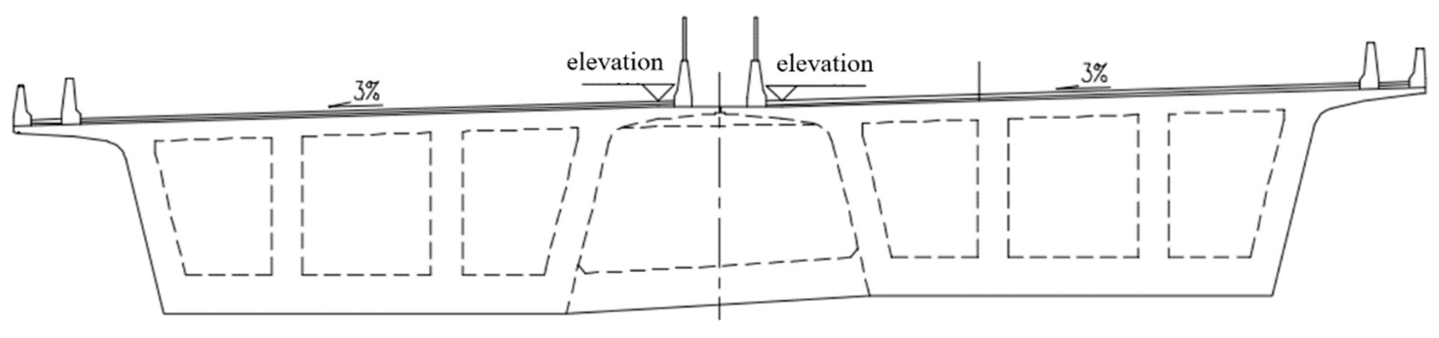
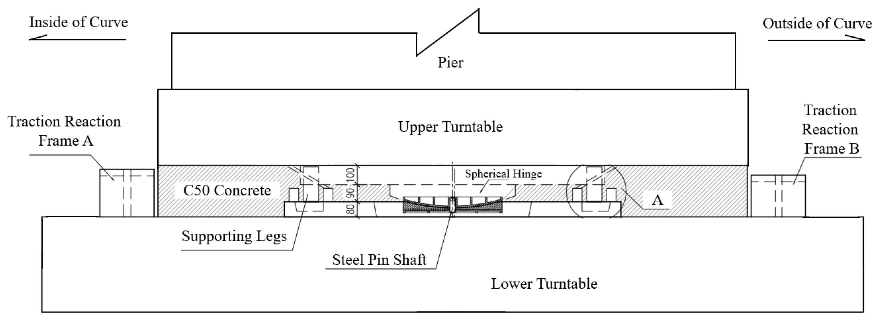
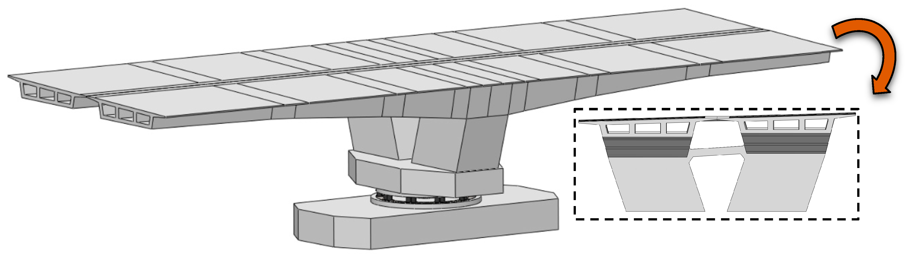
Utilizing Ansys Workbench finite element simulation software, the forces on the steel spherical hinge structure and upper turntable were simulated when the bridge rotates to certain angles and under different off-load conditions. It is worth noting that the bias loading conditions as transverse axial bias loads, longitudinal axial bias loads, and both longitudinal and transverse bias loads were studied in this paper. Through the above simulation analysis, the effect of bias load on the force and deformation of the steel spherical hinge structure was obtained.

2.1. Model Building

Combined with the actual construction drawings, a refined model of the entire bridge was created. The model mainly includes a box girder, bridge pier, upper bearing table, upper turntable, upper steel spherical hinge, steel pin shaft, lower steel spherical hinge, supporting legs, lower turntable, and lower bearing table. In order to improve the speed and accuracy of simulation calculations, traction reaction frames, lower steel spherical hinge bolt holes, PTFE sliding tabs, and filet of concrete structure are omitted. The rotary bridge model is shown in Figure 3; the steel spherical hinge model is shown in Figure 4.
In the process of finite element modeling, in order to improve the speed and accuracy of simulation calculations, traction reaction frame, lower steel spherical hinge bolt hole, PTFE sliding tabs and chamfer of concrete structure are omitted. The traction reaction frame is a concrete unit poured on both sides of the lower bearing platform, which serves to provide positioning and reverse support for the jacks applying the traction force. The lower steel spherical hinge bolt hole is a device designed to provide precise positioning for steel ball hinge installation. The PTFE sliding tabs are installed in the middle of the steel spherical hinge, and its function is to provide lubrication for the steel spherical hinge during the process of rotating the body. None of the above-assumed conditions have any effect on the forces on the structure. The chamfering of the bridge concrete structure accounts for a negligible proportion in the overall structure, and the simplification in this paper is only for the chamfering inside the box girder, which makes the box girder structure more regular, the grid is more finely delineated, and the computation of the simulation is more rapid, and the results are more accurate.

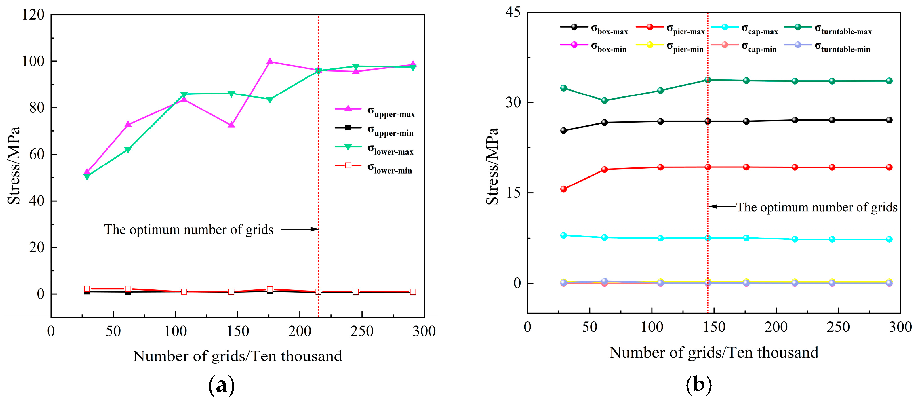
2.2. Material Properties and Grid Delineation

The material properties of each part of the model are shown in Table 1. Reasonable grid shape and size can not only ensure the accuracy of the results but also speed up the simulation solution, Ansys Mesh is used to mesh the model for this analysis. The steel spherical hinge is the core component of the rotary system and the focus of this paper, so the mesh is distributed more finely. Different cell sizes were set, and the results were analyzed; the grid independence verification results of steel spherical hinge and concrete bridge models are shown in Figure 5a,b. The results show that when the number of meshes reaches 1.45 million, the stress value of each part of the concrete bridge tends to be stable. When the number of meshes reaches 2.15 million, the stress value at the steel spherical hinge tends to be stable. After the stress changes, the results tend to be stable; increasing the number of grids has no effect on the simulation results but will reduce the simulation solving speed. Therefore, this paper finally determines that the cell size of the steel spherical hinge and steel pin shaft is 40 mm, the cell size of the supporting legs is 50 mm, the cell size of the rest of the structure is 400 mm, and the total number of grids of the whole model structure is 2,153,111. In Ansys, grids are used to divide a continuous physical model into a series of small cells that are connected by nodes to form an approximate model. Each cell represents a small volume or area, and the nodes are the connection points between these cells. In this way, complex physical problems can be reduced to computable mathematical models for numerical analysis and simulation, and in this paper, a grid refers to a small volume on the model.

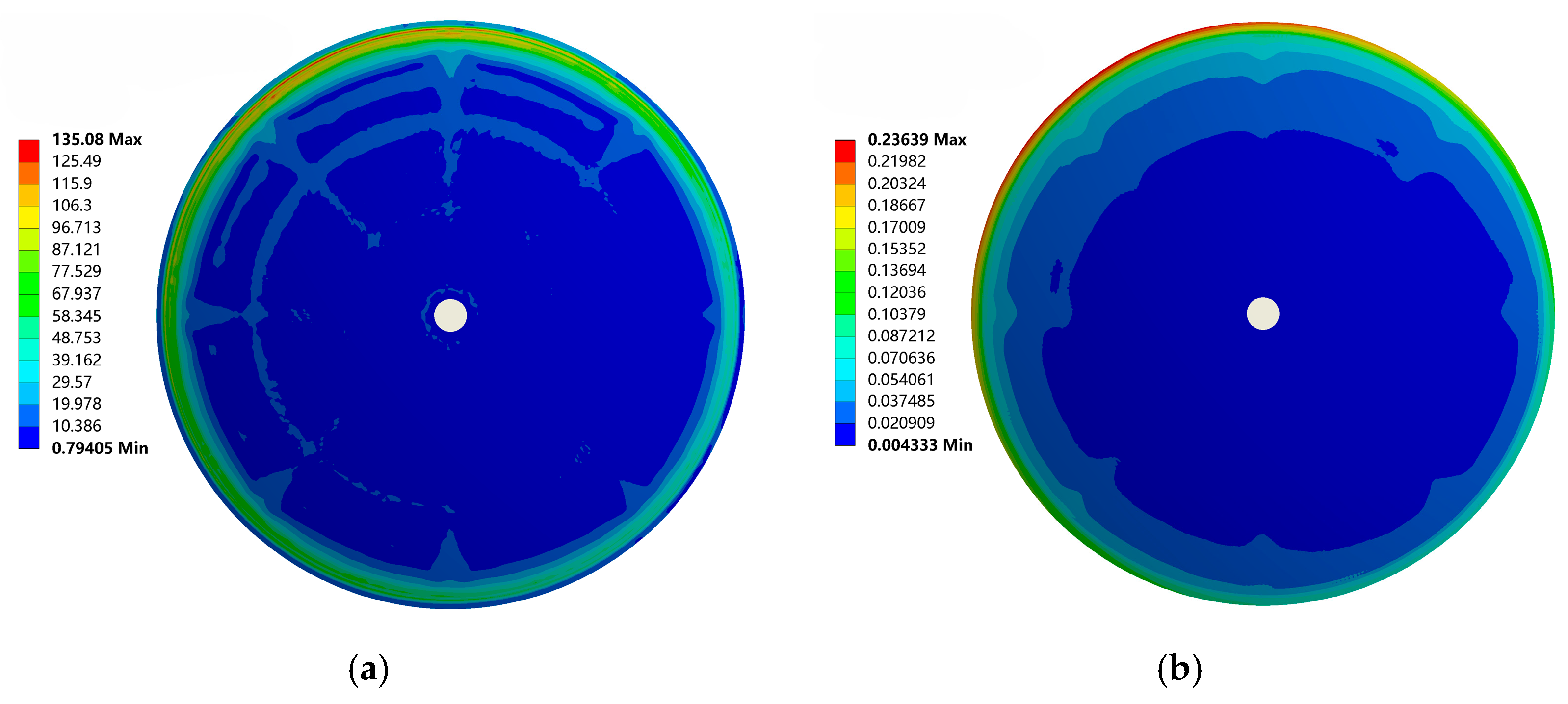
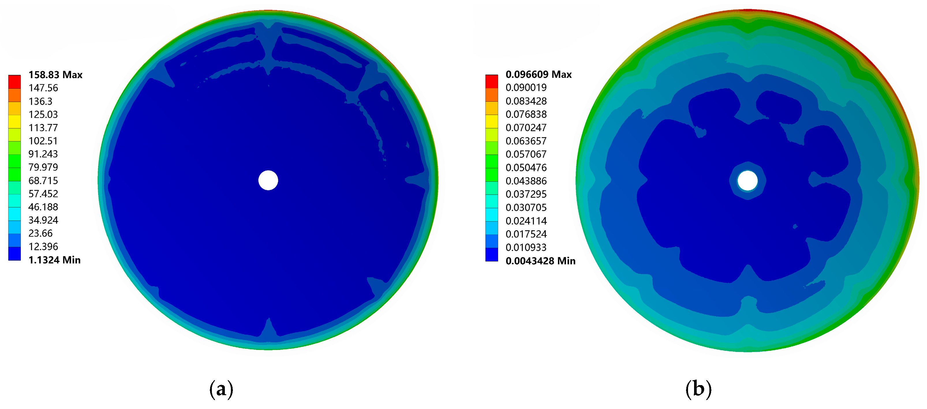
2.3. Analysis of Calculation Results

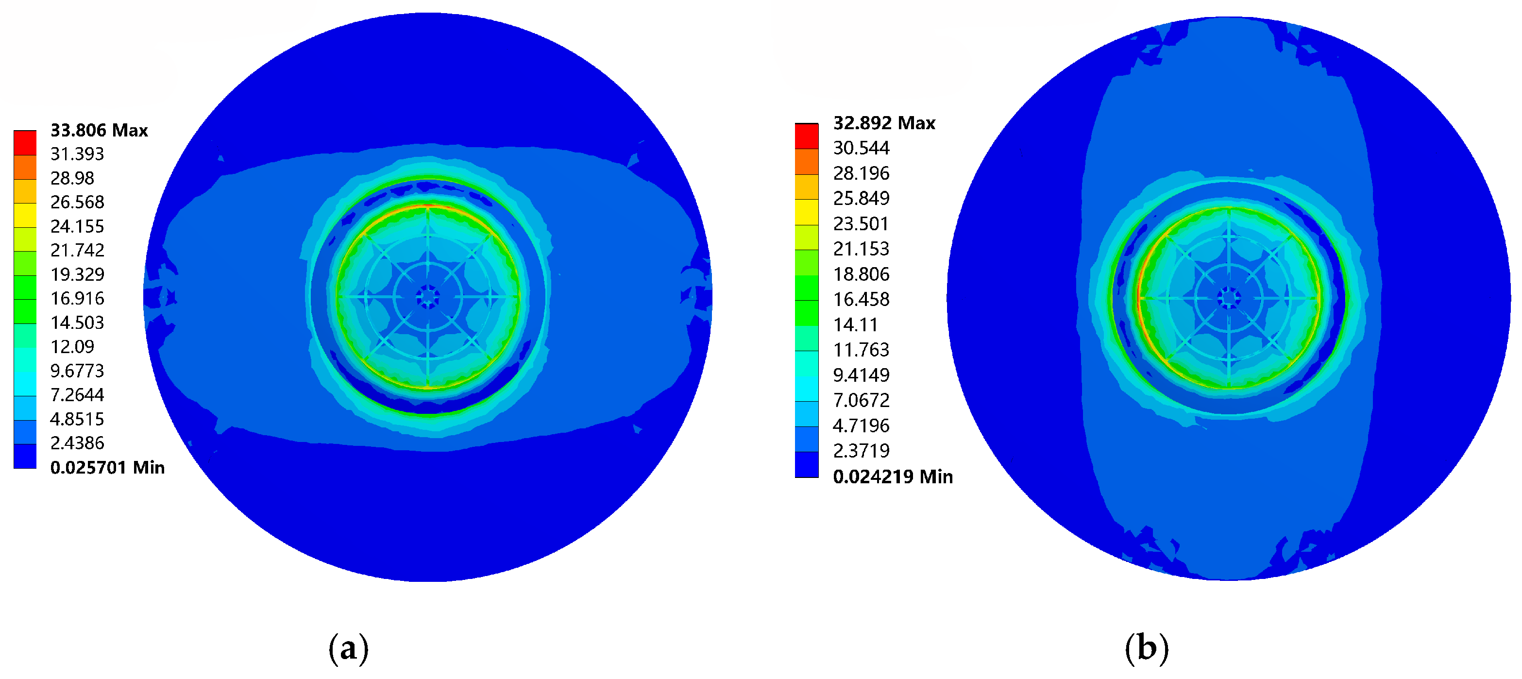
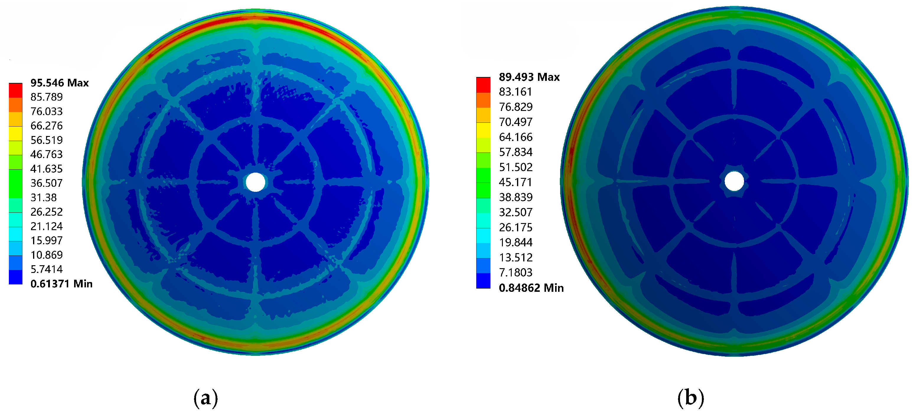
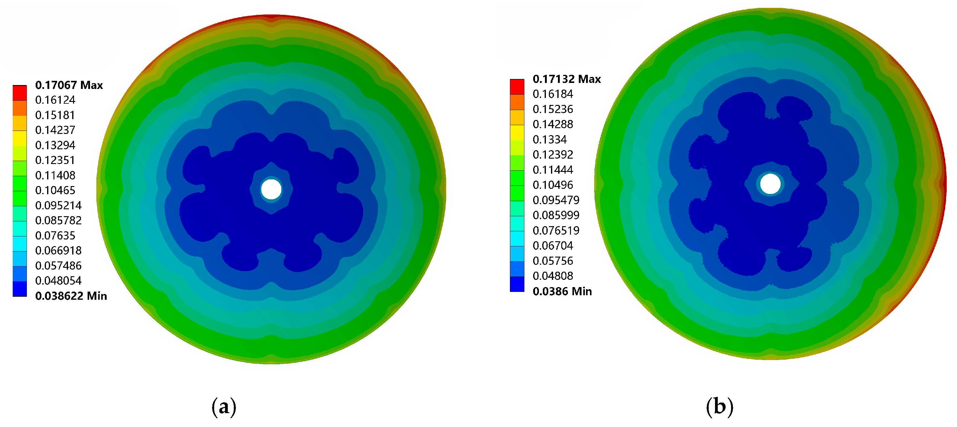
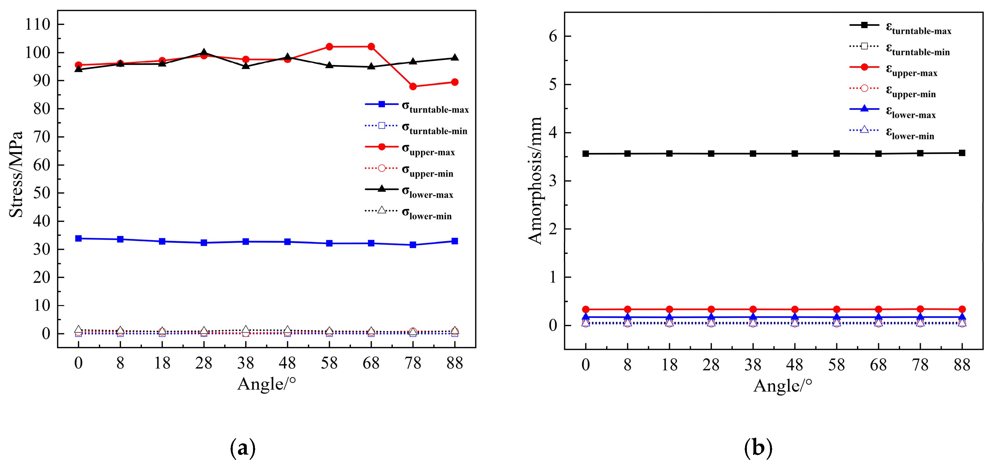
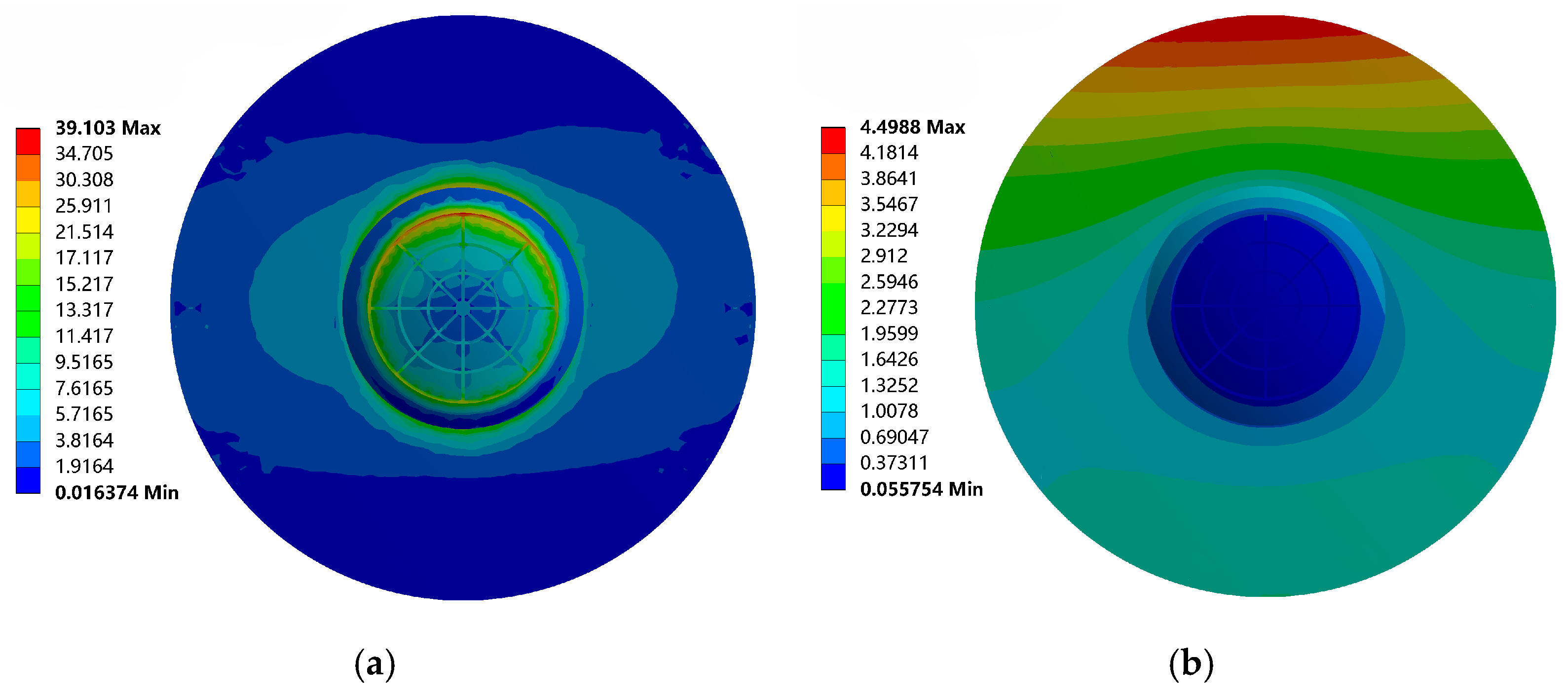
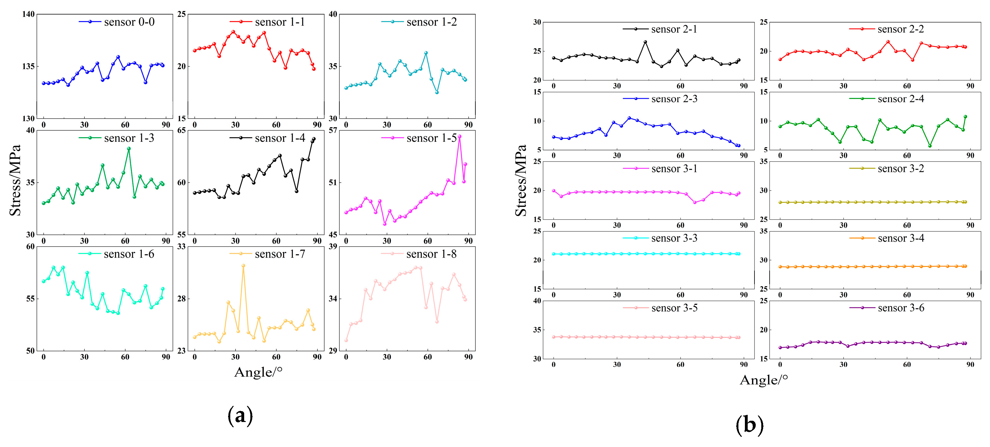
2.3.1. Different Rotation Angles

Bridges were modeled when the rotation angles were 0°, 8°, 18°, 28°, 38°, 48°, 58°, 68°, 78°, and 88°, respectively, and Ansys analysis is performed on different models so as to simulate the state of the whole bridge when the T-shaped rigid bridge is leveled to a particular angle. The simulation results for which the translational angle is 0° (unturned) and 88° (turned) are shown below. Note: In this paper, the equivalent stress clouds are in MPa, and the total deformation clouds are in mm.
The equivalent stress clouds of the upper turntable for unturned and completed turns are shown in Figure 6. From the figure, it can be seen that the maximum stress point is located in the upper turntable and the upper steel spherical hinge contact and is biased to the right width of the transverse bridge, the value of 33.806 MPa, which is smaller than the allowable stress value of 37.5 MPa for the compressive strength of C50 concrete. The overall stress change in the upper turntable is shown as follows: the stress in the contact area between the upper turntable and the outer edge of the upper steel spherical hinge is the largest and gradually shrinks to the edge and center of the upper turntable.
The total deformation clouds of the upper turntable for unturned and completed turns are shown in Figure 7. From the figure, it can be seen that the upper steel spherical hinge and the upper turntable contact with the smallest deformation, and this is the center of the gradual increase to the edge; the largest deformation end is located in the edge of the turntable by the cross-bridge to the right, the value of 3.5761 mm. The overall deformation of the upper turntable showed that the deformation at the contact of the upper turntable with the upper steel spherical hinge was the smallest, and the deformation gradually increased outward along the transverse bridge direction.
The equivalent stress clouds of the upper steel spherical hinge for unturned and completed turns are shown in Figure 8. From the figure, it can be seen that most of the stress values of the upper steel spherical hinged surface are in the interval of 1~25 MPa, and the stress concentration exists only at the edge. The maximum equivalent stress of the upper steel spherical hinge is 95.546 MPa, which is smaller than the yield strength of Q235 steel, satisfying the material requirements, and the maximum stress is located at the contact between the spherical surface of the upper steel spherical hinge and the outer ring bar of the lower steel spherical hinge. The overall stress change in the upper steel spherical hinge shows that the maximum stress is at the edge of the upper steel spherical hinge circumference and gradually shrinks to the center. Due to the existence of several reinforcing bars in the superstructure of the upper steel spherical hinge, the stresses at the corresponding locations on the spherical surface of the upper steel spherical hinge are slightly larger than the stresses in the same circumferential surface.
The total deformation clouds of the upper steel spherical hinge for unturned and completed turns are shown in Figure 9. From the figure, it can be seen that most of the deformation of the steel spherical hinge surface is less than 0.2 mm, and the largest deformation is located at the contact end of the upper steel spherical hinge surface and the lower steel spherical hinge outer ring bar, and the deformation value is 0.32978 mm. The overall deformation of the upper steel spherical hinge shows the following trend: the deformation of the upper steel spherical hinge circumferential edge is the largest and gradually shrinks to the center.
The equivalent stress clouds of the lower steel spherical hinge for unturned and completed turns are shown in Figure 10. From the figure, it can be seen that most of the stress values of the lower steel spherical hinge surface are in the interval of 1~23 MPa, and the stress concentration exists only at the edges. The maximum value of equivalent stress of the lower steel spherical hinge is 98.04 MPa, which is less than the yield strength of Q235 steel and meets the material requirements. The overall stress change in the lower steel spherical hinge shows a trend of large stresses at the circumferential edge of the lower steel spherical hinge and gradually shrinking towards the center. Influenced by the reinforcement of the upper steel spherical hinge, the stress at the corresponding reinforcement on the lower steel spherical hinge surface is slightly larger than the stress in the same circumference.
The total deformation clouds of the lower steel spherical hinge for unturned and the completed turns are shown in Figure 11. From the figure, it can be seen that most of the deformation of the lower steel spherical hinge surface is less than 0.12 mm, and the maximum value of deformation is 0.17132 mm. The overall deformation of the lower steel spherical hinge shows the following trend: the deformation of the lower steel spherical hinge circumferential edge is the largest, and it gradually shrinks to the center.
By analyzing the equivalent stress cloud diagrams before and after the upper and lower steel spherical hinges were rotated, it can be seen that under the working condition without interference from external factors, the stress changes are orderly, and the maximum stress points are all in the right amplitude of the transverse bridge, and all of them are presented as the big stress at the edge of the circumference of the steel spherical hinges, which is gradually narrowed down to the center. By analyzing the deformation cloud diagrams before and after the upper and lower steel spherical hinges were rotated, it can be seen that under the working condition without interference from external factors, the maximum point of deformation was in the right amplitude of the transverse bridge, and all of them showed the trend that the deformation of the circumferential edges of the steel spherical hinges was large and gradually narrowed down to the center.
The summary diagrams of stresses and deformations of the upper turntable, upper steel spherical hinge, and lower steel spherical hinge at different flat rotation angles are shown in Figure 12. From the figure, it can be seen that under the ideal working condition, with the rotation of the bridge, only the upper and lower steel spherical hinges have a fluctuation of about 5 MPa in stress value; the rest of the components stress and deformation changes are minimal, which can be seen that the rotation process is quite smooth, and the stress on each component is less than its permissible stress value, and the deformation meets the engineering requirements.

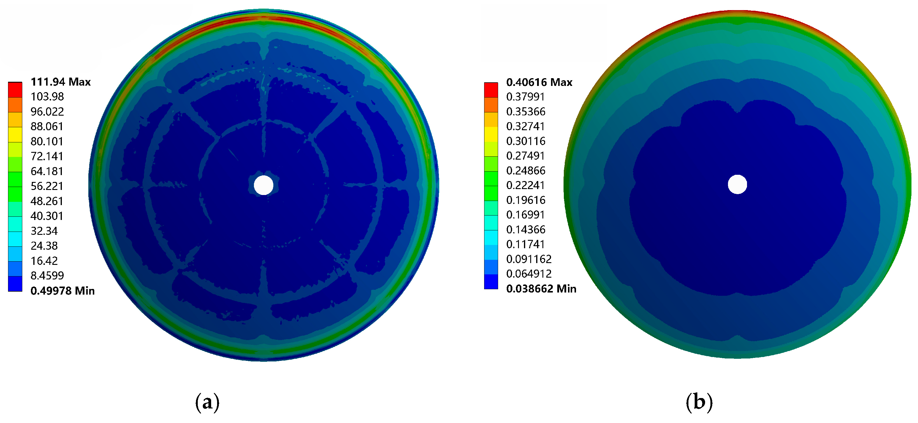
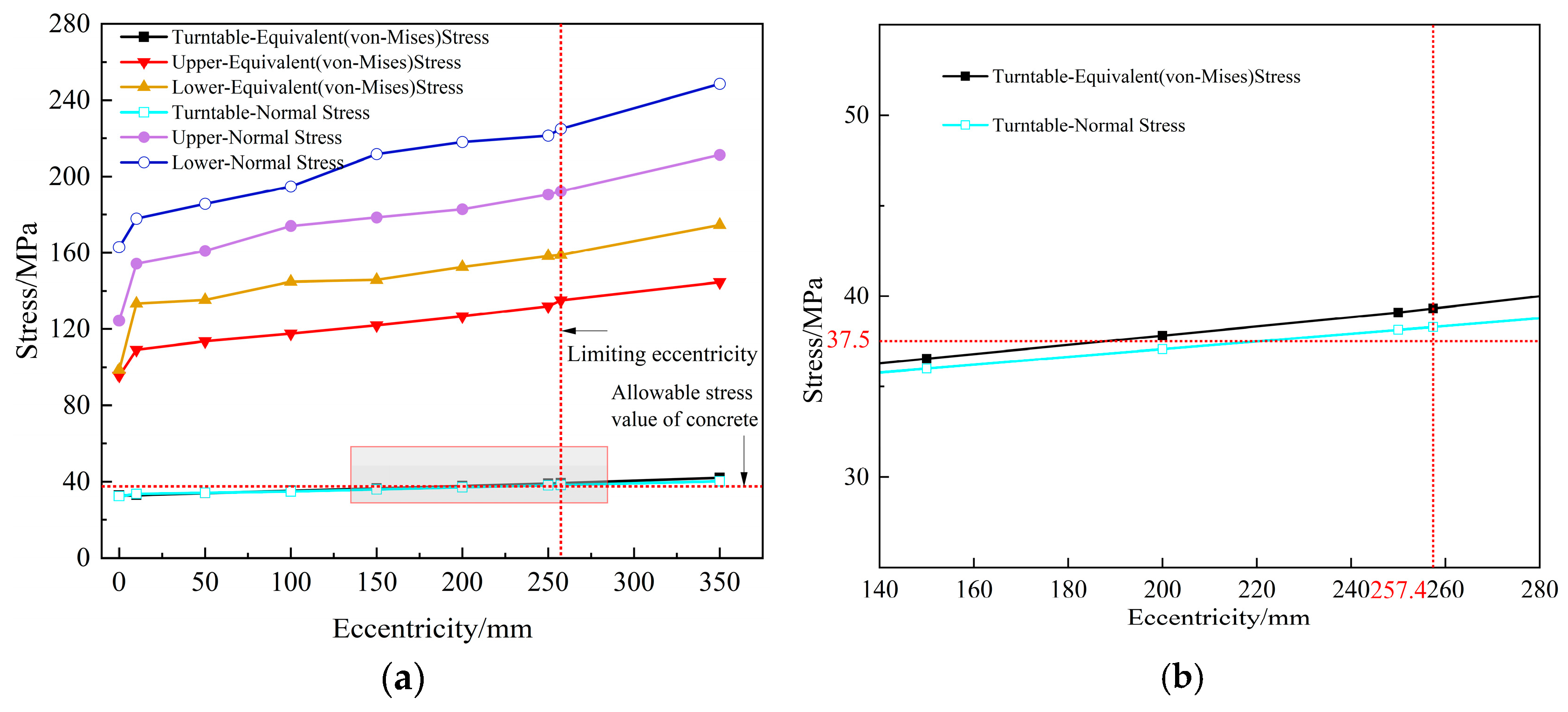
2.3.2. Transverse Axial Bias Loads

The object of this paper is that the steel spherical hinge drag moment is greater than the unbalance moment of the swiveling body, which means that the swiveling body maintains the equilibrium state through the steel spherical hinge drag moment and the swiveling body’s own unbalance moment [28]; the swiveling body structure does not rotate.
When the steel spherical hinge friction moment is greater than the unbalance moment of the swiveling body, the maximum allowable eccentricity of the swiveling body structure can be obtained from Equation (1) [29]. The maximum allowable eccentricity of the T-shaped rigid bridge is calculated to be 0.2574 m. Therefore, the effect of eccentricity values of 0 mm, 10 mm, 50 mm, 100 mm, 150 mm, 200 mm, 250 mm, 257.4 mm, and 350 mm on the steel spherical hinge and upper turntable has been investigated, respectively. In this paper, in order to change the eccentricity value, the overall eccentricity of the concrete structure above the steel spherical hinge is changed, and the model is analyzed numerically.
e max = M z G = 0.99 μ GR G = 0.99 μ R .
In the formula, the variables are as follows:
MZ—Friction moment of the steel spherical hinge, N·m;
G—Self-weight of bridges, kN;
R—Radius of steel spherical hinge, m;
μ—Coefficient of static friction of steel spherical hinge.
Let me explain in detail the two technical words above. Eccentricity limit: During the construction of a transverse bridge, the steel spherical hinge will have a certain amount of eccentricity with its concrete superstructure, which is unavoidable and can be caused by the design of the drawings as well as by the construction process. The maximum permissible eccentricity during the construction of the bridge is the eccentricity limit. Bias loads: As a result of the eccentricity condition of the transverse bridge, the superstructure will generate a certain amount of bias load on the steel spherical hinge, the degree of which is related to the size of the eccentricity and the level of applied load. Depending on the location of the eccentricity, the bias loads can be classified as transverse axial bias loads, longitudinal axial bias loads, and longitudinal and transverse axial bias loads.
The effect of different transverse axial bias loads on the upper turntable and steel spherical hinge stresses was obtained by Ansys finite element analysis, and the results are shown in Figure 13a. From the figure, it can be seen that the stress on the steel spherical hinge structure and the upper turntable increases with the increase in the eccentricity distance; the stress on the upper turntable is obviously smaller than that on the steel spherical hinge structure. Eccentricity of 257.4 mm at the local enlargement shown in Figure 13b; from the figure, it can be seen that when the limit eccentricity is 257.4 mm, the upper turntable normal compressive stress has been close to the allowable stress value of C50 concrete compressive strength of 37.5 MPa, which is in the limit of the working condition. At this time, the equivalent stress on the upper turntable has reached 39.103 MPa, exceeding the allowable stress value. When the eccentricity is 210 mm, the equivalent stress on the upper turntable is at the limit working condition. When the eccentricity distance is 350 mm, the stress suffered by the steel spherical hinge structure is still far less than its yield strength, so the size of the eccentricity distance of the bridge structure is mainly limited by the upper turntable. The ultimate transverse axial bias loads of this bridge are 210 mm, and the eccentricity distance is too large, which leads to the collapse of the upper turntable and the structural overturning of the bridge. Therefore, the size of the transverse axial bias loads should be correctly controlled so as to ensure the safety and stability of the bridge construction.
Among them, the simulation results with an eccentricity of 0 mm are shown in Figure 6, Figure 7, Figure 8, Figure 9, Figure 10 and Figure 11, the simulation results with an eccentricity of 257.4 mm are shown in the following figures, and the cloud diagrams of the equivalent stresses and deformations of the upper turntable are shown in Figure 14. The cloud diagrams of the upper steel spherical hinge equivalent stress and deformation are shown in Figure 15; the cloud diagrams of the lower steel spherical hinge equivalent stress and deformation are shown in Figure 16. From the figure, it can be seen that when the ultimate eccentricity distance is reached, the stress concentration in each part of the rotating device is more obvious than when it is not eccentric, in which the stress at the stress concentration of the upper turntable has been as high as 39.103 MPa, and the deformation has reached 4.4988 mm, which has exceeded the specified value, and the rotating bridge has been overturned. The stress concentration at the steel spherical hinge is also more obvious, although it does not reach its allowable stress value, but the stress concentration will cause material fracture, so that the material produces fatigue cracks. In order to ensure the safety of the project, it is still necessary to pay attention to the impact of transverse axial bias loads on the bridge turning process.

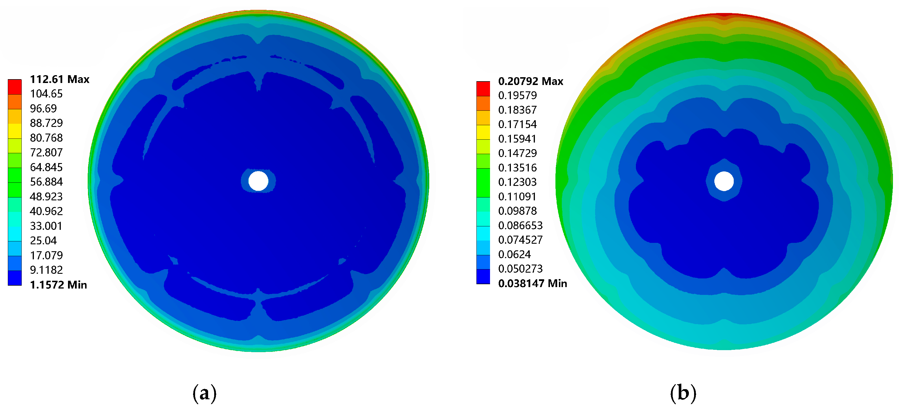
2.3.3. Longitudinal Axial Bias Loads

The effect of different longitudinal axial bias loads on the upper turntable and steel spherical hinge stresses was obtained by Ansys finite element analysis; the results were shown in Figure 17a. When the eccentricity value is 10 mm, the stress on each rotating device increases steeply, which was analyzed to be due to the large longitudinal span of the bridge girder box, so the eccentricity condition has a greater impact on the rotating device. By increasing the eccentricity on this basis, the rise in stress decreases, but the value of stress increases with increasing eccentricity. The local enlarged diagram at the eccentricity distance of 257.4 mm was shown in Figure 17b, from which it can be seen that when the ultimate eccentricity distance of 257.4 mm was reached, the normal compressive stress on the upper turntable was close to the permissible stress value of 37.5 MPa for the compressive strength of C50 concrete, which was in the ultimate working condition. At this time, the equivalent force on the upper turntable has reached 38.02 MPa, exceeding the allowable stress value. When the eccentricity is 200 mm, the equivalent force on the upper turntable is at the limit working condition. When the eccentricity is 257.4 mm, the stress on the steel spherical hinge is still much less than its yield strength. Therefore, under the influence of longitudinal axial bias loads, the limiting longitudinal axial bias loads distance of this bridge is 200 mm due to the properties of the material of the upper turntable, but longitudinal axial bias loads distance should be reduced as much as possible in order to ensure the safety and stability of the bridge construction.
The simulation results with an eccentricity of 257.4 mm are shown in the following figures; the cloud diagrams of the equivalent stresses and deformations of the upper turntable are shown in Figure 18. The cloud diagrams of the upper steel spherical hinge equivalent stress and deformation are shown in Figure 19; the cloud diagrams of the lower steel spherical hinge equivalent stress and deformation are shown in Figure 20. From the figure, it can be seen that when reaching the limit of eccentricity, the rotating device of each part of the stress concentration is more obvious than not eccentric; the pattern of stress change is the same as that of transverse axial bias loads, and the stress value is slightly larger than that of transverse axial bias loads. The stress value is slightly larger than longitudinal axial bias loads; the maximum stress value point is located in the eccentricity position. In order to ensure the safety of the project, the need to pay attention to longitudinal axial bias loads of the conditions of the bridge to the impact of the process of the bridge turning.

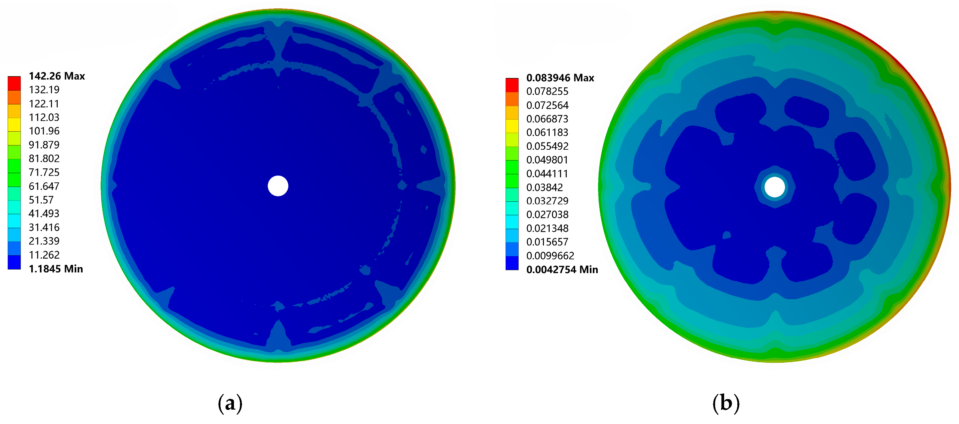
2.3.4. Longitudinal and Transverse Axial Bias Loads

The effect of different longitudinal and transverse axial bias loads on the upper turntable and steel spherical hinge stresses was obtained by Ansys finite element analysis; the results were shown in Figure 21a. When the eccentricity value is 10 mm, the stress on each rotating device increases steeply, which was analyzed to be due to the longitudinal and transverse axial bias loads together, and the bottom of the bridge carries more pressure when it is skewed, so the eccentricity condition has a greater impact on the rotating device. By increasing the eccentricity on this basis, the rise in stress decreases, but the value of stress increases with increasing eccentricity. When the eccentricity value is 257.4 mm, the normal compressive stress of the lower steel spherical hinge has reached 224.98 MPa, which is close to the yield strength of the material, and the bridge is in danger of overturning. The local enlargement at an eccentricity of 257.4 mm is shown in Figure 21b. From the figure, it can be seen that when the ultimate eccentricity of 257.4 mm is reached, the stresses on the upper turntable have exceeded the permissible stress value of 37.5 MPa for the compressive strength of C50 concrete, and the bridge has overturned. When the eccentricity is 180 mm, the equivalent force on the upper turntable is at the limit working condition. From the above conclusion, it can be seen that the bridge can withstand the longitudinal and transverse axial bias loads that are less than the unidirectional eccentricity value. In order to ensure the safety and stability of the bridge construction, the longitudinal and transverse axial bias loads should be greatly reduced.
The simulation results with an eccentricity of 257.4 mm are shown in the following figures; the cloud diagrams of the equivalent stresses and deformations of the upper turntable are shown in Figure 22. The cloud diagrams of the upper steel spherical hinge equivalent stress and deformation are shown in Figure 23; the cloud diagrams of the lower steel spherical hinge equivalent stress and deformation are shown in Figure 24. From the figure, it can be seen that when reaching the limit of eccentricity, the rotating device of each part of the stress concentration is more obvious than not eccentric; the pattern of stress change is the same as the above two eccentric working conditions; the stress value is slightly larger than the unidirectional eccentricity, and the maximum stress value point is located at the eccentricity position. In order to ensure the safety of the project, it is necessary to pay attention to the influence of longitudinal and transverse axial bias loads on the process of bridge turning.
This is shown by analyzing the three different eccentricities: transformer bridges operate under eccentricity conditions; the phenomenon of stress concentration occurs in all components of the rotating system and increases with the increase in eccentricity; the strength of the upper turntable determines the permissible eccentricity value of the bridge.

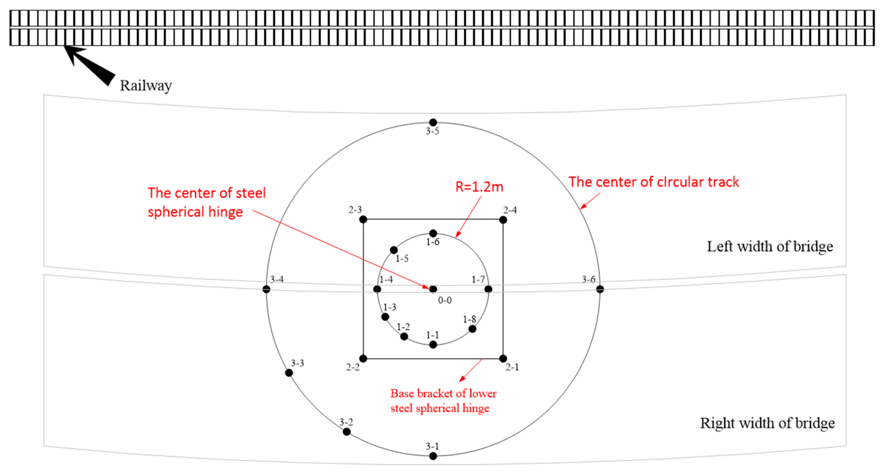
3. Monitoring Program and Results

In order to ensure the safety and stability of the leveling process of T-shaped rigid bridges [30,31], it is necessary to monitor the stresses of some bridge members in real time [32,33]. However, the stress at the steel spherical hinge cannot be directly monitored by the sensor. Therefore, the monitoring scheme in this paper is to install vibrating string stress gauges underneath the steel spherical hinge, the spherical hinge steel frame, and the circular track. By monitoring the stress change in the steel support structure in the lower turntable, the deflection of the T-shaped rigid bridge in the process of turning can be derived, which indirectly reacts to the change rule of the stress at the steel spherical hinge.
For this monitoring, nineteen vibrating string surface stress gauges were placed. The arrangement scheme of the stress gauges is shown in Figure 25, where all the stress gauges are welded to the steel support structure of the lower turntable at the same depth of arrangement. The actual arrangement of the stress gauges is shown in Figure 26a, where changes in stress values are accurately monitored by welding the iron blocks at the ends of the stress gauges to the steel support structure. The actual arrangement of the encoder is shown in Figure 26b; its function is to monitor the turning angle of the T-shaped rigid bridge in real time and summarize the data through the collection box, so as to obtain the correspondence table between the turning angle and the stress value. The data collection box is shown in Figure 26c.
As the T-shaped rigid bridge turned, the stress values monitored by each stress gauge are shown in Figure 27a,b. Stress gauges were installed at the concrete steel support structure directly below the steel spherical hinge; the variation curves of the monitored stresses are shown in Figure 27a. Stress gauges were installed at the concrete steel support structure below the lower steel spherical hinge base bracket and supporting legs; their monitored stress profiles are shown in Figure 27b. It is obvious that the stress values at each stress monitoring point will change with the turn of the body. This suggests that multiple unfavorable factors, such as unbalanced traction forces and wind loads, can have an impact on the smoothness of the bridge rotation during the actual turning process. Initial stress of the sensor at 0° is the increment of the stress value at each monitoring point during the period from the lower turntable concrete placement to the completion of bridge construction.
From the figure, it can be seen that with the rotation of the bridge, the stress value of each monitoring point under the steel spherical hinge changed significantly; the magnitude of the change was within 5 MPa. The stress difference between the start of the turn (0°) and the end of the turn (88°) is less than 5 MPa. This indicates that the transfer bridge complies with the construction requirements despite the slight deflection. In the data, only the stress value numbered 1-1 decreased by 1.76 MPa; the stress values of the rest of the monitoring points increased to varying degrees, indicating that the right side of the bridge weighed the most before the turnaround.
The magnitude of the change in stress values at the lower steel spherical hinge base bracket was greater. It indicates that the bridge was not in a smooth condition during the turning process. Slight deflection occurs under the influence of external unstable factors. The stress values for numbers 2-1 and 2-2 are much larger than those for numbers 2-3 and 2-4, which indirectly verifies that the T-shaped rigid bridge has a greater mass in the rightward direction of the transverse bridge.
There is a noticeable change in the values read by the sensors numbered 3-1 and 3-6 below the supporting legs; the rest of the values do not fluctuate significantly. Therefore, it can be deduced that the bridge as a whole was deflected to the right width of the big mileage end, and the supporting legs were in contact with the circular track during the process of rotation. In particular, the change in stress values in the interval from 62.630° to 74.907° was significant, with a brief separation of the supporting legs from the circular track followed by contact.
This paper focuses on the change rule of stress at the steel spherical hinge, so the stress values at the monitoring point below the steel spherical hinge were analyzed in detail. Since the stress on the contact surface of the steel spherical hinge could not be directly monitored by installing sensors, the monitoring stress data of the concrete steel support structure of the lower turntable at the same location were compared with the simulation data of the lower steel spherical hinge. The results are shown in Figure 28, where Figure 28a shows a comparison of data from monitoring points 1-1 and 1-2, Figure 28b shows a comparison of data from monitoring points 1-3 and 1-4, Figure 28c shows a comparison of data from monitoring points 1-5 and 1-6, and Figure 28d shows a comparison of data from monitoring points 1-7 and 1-8. It can be seen through the analysis: There are strong fluctuations in the stress change curve monitored by the sensor, while the simulated values are smoother than the measured values, which is due to the influence of many unstable factors in the actual process of turning the body, such as unbalanced traction force and wind load, which lead to a sharp change in the value of stress at a certain moment and then stabilize gradually. In the simulation, external factors cannot be taken into account, only the model itself, so the simulation results are smoother compared with the measured values. Through careful comparison, it can be found that the measured and simulated values of each monitoring point have the same trend, and all of them are carrying out the same lifting and lowering changes at the same time, which indirectly proves the correctness of the simulation results and the feasibility of the monitoring scheme. Therefore, the scheme of installing stress gauges in the concrete bearing platform can indirectly reflect the changes in the ball hinge and even the overall stress of the bridge.
During the design process, engineers can clearly identify the sources of eccentricity effects and carry out corresponding mechanical analyses and calculations to assess the impact of eccentricity on the overall structure; when designing bridges, it usually relies on structural analysis software and calculation models. The paper can provide some specific simulation means for assessing the influence of the eccentricity effect on the bridge structure, and the engineers can dynamically adjust and optimize according to the actual situation; in the construction of the bridge, the parts sensitive to the eccentricity effect are specially strengthened; this paper demonstrates the specific performance of the eccentricity effect in the large-tonnage asymmetric T-rigid structure transverse bridges through specific cases.
During bridge construction, engineers can assess the overall condition of the bridge based on simulated stress maps to ensure that the bridge meets construction standards. During the rotation of the bridge, engineers can visualize the stress change in the steel spherical hinge and the lower bearing platform through the measured stress value, so as to deduce the eccentricity position of the bridge and the specific load value. By analyzing the eccentric loads, it is possible to predict the risk of bridge collapse during operation and make timely adjustments to avoid overturning.

4. Discussion and Conclusions

The problem of stress variations in the swiveling support system of a large tonnage asymmetric T-shaped rigid swiveling bridge has been investigated in this paper. The bridge model was built using SolidWorks, and the bridge swiveling process was numerically modeled using Ansys. The main conclusions are as follows:
(1) During rotation, the maximum compressive stress in the upper turntable is located in the contact area with the outer edge of the upper steel spherical hinge; the stress value is 33.806 MPa, and the stress gradually decreases in all directions. The maximum compressive stress of the steel spherical hinge is located at the edge of its own circumference and is accompanied by stress concentration. The maximum compressive stress values of the upper and lower steel spherical hinges are 95.546 MPa and 98.04 MPa, respectively, and the stress decreases with the decrease in the radius of the steel spherical hinge.
(2) Under the theoretical transverse, longitudinal, and longitudinal-transverse limiting eccentricity conditions, the stress on the upper turntable has reached 39.103 MPa, 38.02 MPa, and 39.316 MPa, respectively. All of the above exceed the allowable stress value of the material, while the steel spherical hinge still meets the design requirements, so the ultimate eccentricity of the rotating bridge is mainly affected by the strength of the upper turntable. The transverse, longitudinal, and longitudinal-transverse limit bias loads of this bridge are 210 mm, 200 mm, and 180 mm, respectively.
(3) Under the three eccentric working conditions, the stress change rule of each member is the same; only the stress value and the direction of stress concentration are different. The maximum stress value point is located in the eccentric position, and it increases with the increase in eccentricity. In descending order, the effects of the three eccentricity conditions on this bridge were transverse axial, longitudinal axial, and longitudinal and transverse axial bias loads. In order to ensure the safety of the project, it is necessary to focus on the influence of each eccentricity condition on the bridge turning process.
(4) During the actual turning process, due to the interference of the external load, the change amplitude of the stress value at each monitoring point is within the interval of 0~5 MPa. The measured values of each monitoring point are consistent with the trend of simulation values. The monitoring method of deploying stress gauges at the steel support structure of the lower bearing platform provides a new method to obtain the stress pattern of the steel spherical hinge and even the bridge as a whole.

Author Contributions

Methodology, E.Z.; software, Y.W.; validation, E.Z.; formal analysis, S.G.; resources, Y.W.; data curation, Y.W.; writing—original draft preparation, Y.W.; writing—review and editing, E.Z. and H.L.; visualization, P.L.; supervision, E.Z. and H.L.; project administration, H.L. All authors have read and agreed to the published version of the manuscript.

Funding

This research was funded by the Design and Development of Intelligent Monitoring and Early Warning System for Horizontal Turning of Bridges [grant number 2023208] and Research on Key Technology of Horizontal Turning Construction of Large-Tonnage Bridges [grant number 2022138].

Institutional Review Board Statement

Not applicable.

Informed Consent Statement

Not applicable.

Data Availability Statement

The original contributions presented in the study are included in the article; further inquiries can be directed to the corresponding author.

Conflicts of Interest

The funders had no role in the design of the study; in the collection, analyses, or interpretation of data; in the writing of the manuscript; or in the decision to publish the results.

References

  1. Zhou, X.; Zhang, X. Thoughts on the Development of Bridge Technology in China. Engineering 2019, 5, 1120–1130. [Google Scholar] [CrossRef]
  2. Su, M.; Wang, J.; Peng, H. State-of-the-art review of the development and application of bridge rotation construction methods in China. Sci. China Technol. Sci. 2021, 64, 1137–1152. [Google Scholar] [CrossRef]
  3. Xi, R.; He, Q.; Meng, X. Bridge monitoring using multi-GNSS observations with high cutoff elevations: A case study. Measurement 2021, 168, 108303. [Google Scholar] [CrossRef]
  4. Shaikh, A.; Osei-Kyei, R.; Hardie, M. A critical analysis of safety performance indicators in construction. Int. J. Build. Pathol. Adapt. 2020, 39, 547–580. [Google Scholar] [CrossRef]
  5. Ha, T.; Fukada, S. Nondestructive damage detection in deteriorated girders using changes in nodal displacement. J. Civ. Struct. Health Monit. 2017, 7, 385–403. [Google Scholar] [CrossRef]
  6. Pettorruso, C.; Quaglini, V. Conceptual Design of Seismic Retrofit of Existing Bridges by Deck Isolation: Assessment of Effectiveness. Appl. Sci. 2024, 14, 7353. [Google Scholar] [CrossRef]
  7. Wang, J.; Sun, Q. Parameter sensitivity analysis of stability of T-shaped rigid frame bridge by adopting swivel construction method. Multidiscip. Model. Mater. Struct. 2020, 16, 1203–1231. [Google Scholar] [CrossRef]
  8. Ono, R.; Ha, T.; Fukada, S. Analytical study on damage detection method using displacement influence lines of road bridge slab. J. Civ. Struct. Health Monit. 2019, 9, 565–577. [Google Scholar] [CrossRef]
  9. Hong, Z.; Siyuan, R.; Ming, L. Design and development of a two degree-of-freedom rotational flexure mechanism for precise unbalance measurements. J. Mech. Robot. 2017, 9, 041013. [Google Scholar]
  10. Shao, J.; Duan, M.; Yang, W. Research on the critical technique of synchronous rotation construction with large angle for T-shape curve rigid frame bridge. Sci. Rep. 2022, 12, 1530. [Google Scholar] [CrossRef] [PubMed]
  11. Dai, W.; Zuo, J.; Liu, D. Tribological Properties and Seasonal Freezing Damage Evolution of Rotating Spherical Hinge Self-Lubricating Coating. Appl. Sci. 2022, 12, 8329. [Google Scholar] [CrossRef]
  12. Luo, L. Accurate calculation method of vertical friction moment of spherical hinge in bridge rotation construction. Railw. Eng. 2020, 60, 27–30. [Google Scholar]
  13. Vilventhan, A.; Rajadurai, R. 4D Bridge Information Modelling for management of bridge projects: A case study from India. Built Environ. Proj. Asset Manag. 2019, 10, 423–435. [Google Scholar] [CrossRef]
  14. Sanni-Anibire, M.; Mohamad, Z.; Olatunji, S.O. Causes of delay in the global construction industry: A meta analytical review. Int. J. Constr. Manag. 2020, 22, 1395–1407. [Google Scholar] [CrossRef]
  15. Guo, W.; Guo, X.; Wang, Z. Investigation on Moisture Damage Prevention of a Spherical Hinge Structure of a Swivel Bridge. Coatings 2020, 10, 955. [Google Scholar] [CrossRef]
  16. Haji, D.; Behnam, B.; Sebt, M. BIM-Based Safety Leading Indicators Measurement Tool for Construction Sites. Int. J. Civ. Eng. 2022, 21, 265–282. [Google Scholar] [CrossRef]
  17. Sciegaj, A. A Diagnostic Method Based on Deflection Analysis for Monitoring Post-elastic Response of Beams. Int. J. Civ. Eng. 2023, 21, 839–855. [Google Scholar] [CrossRef]
  18. Stefanidou, S.; Paraskevopoulos, E. Seismic fragility analysis of railway reinforced concrete bridges considering real-time vehicle-bridge interaction with the aid of co-simulation techniques. Earthq. Eng. Struct. Dyn. 2022, 51, 2137–2161. [Google Scholar] [CrossRef]
  19. Che, X.; Zhang, X. Overturning resistance of large tonnage T-shaped rigid frame bridge during turning process. China J. High. Transp. 2014, 27, 66–72. [Google Scholar]
  20. Liu, Y.; Tan, Z.; Yang, C. Refined finite element modeling of a damaged bridge with virtual distortion method coupling solid super element. Mech. Syst. Signal Process. 2017, 93, 559–577. [Google Scholar] [CrossRef]
  21. Parson, S. Investigation on determining thermal stress in massive concrete structures. ACI 1996, 93, 96–101. [Google Scholar]
  22. Kim, K.; Lee, H. Analysis of target configurations under dead loads for cable- supported bridges. Comput. Struct. 2001, 79, 2681–2692. [Google Scholar] [CrossRef]
  23. Che, X.; Zhou, Q.; Guan, L. Research on optimization of radial stress calculation method for large tonnage ball hinge of rotary bridge. J. Wuhan Univ. Technol. (TSE) 2014, 38, 356–358. [Google Scholar]
  24. Zhang, X. Research on Ball Hinge Analysis and Control of Bridge Construction by Flat Rotating Method. Master’s Thesis, China Academy of Railway Sciences, Beijing, China, 2017. [Google Scholar]
  25. Huang, S.; Tang, Y.; Yuan, Z. Stress analysis and optimization method of contact surface of bridge rotating body construction. J. Harbin Eng. Univ. 2020, 41, 1790–1796. [Google Scholar]
  26. Liu, T.; Yu, Q.; Fan, J. Concrete spherical joint contact stress distribution and overturning moment of swing bridge. Structures 2020, 28, 1187–1195. [Google Scholar] [CrossRef]
  27. Ma, X. Research on Key Technology of Super-Large Tonnage T Rotations. Master’s Thesis, Shandong Jiaotong University, Jinan, China, 2023. [Google Scholar]
  28. Salas, R.; Hallowell, M. Predictive validity of safety leading indicators: Empirical assessment in the oil and gas sector. J. Constr. Eng. Manag. 2016, 142, 04016052. [Google Scholar] [CrossRef]
  29. Liu, S.; Liu, J.; Huang, Y. Optimization of Swivel Spherical Hinge Structure Design Based on the Response Surface Method. Sustainability 2023, 15, 10356. [Google Scholar] [CrossRef]
  30. Yan, Y.; Wu, X.; Wu, Z. Bridge safety monitoring and evaluation based on hesitant fuzzy set. Alex. Eng. J. 2022, 61, 1183–1200. [Google Scholar] [CrossRef]
  31. Han, S.; Joo, H.; Choi, S. Experimental Study on Shear Capacity of Reinforced Concrete Beams with Corroded Longitudinal Reinforcement. Materials 2019, 12, 837. [Google Scholar] [CrossRef]
  32. Wang, J. Experimental research on compressive strength of UHPC spherical hinge. Int. J. Struct. Integr. 2019, 11, 354–378. [Google Scholar]
  33. Montenegro, P.; Carvalho, H.; Ribeiro, D. Assessment of train running safety on bridges: A literature review. Eng. Struct. 2021, 241, 112425. [Google Scholar] [CrossRef]
Figure 1. Standard cross-section layout of bridge.
Applsci 14 11799 g001
Figure 2. Structure of rotary spherical hinge.
Applsci 14 11799 g002
Figure 3. Rotary bridge model.
Applsci 14 11799 g003
Figure 4. Steel spherical hinge model.
Applsci 14 11799 g004
Figure 5. Grid independence verification: (a) steel spherical hinge; (b) concrete bridge.
Applsci 14 11799 g005
Figure 6. Equivalent stress clouds of the upper turntable: (a) the state of no rotation (angle = 0°); (b) the state of rotation (angle = 88°).
Applsci 14 11799 g006
Figure 7. Total deformation clouds of the upper turntable: (a) the state of no rotation (angle = 0°); (b) the state of rotation (angle = 88°).
Applsci 14 11799 g007
Figure 8. Equivalent stress clouds of upper steel spherical hinge: (a) the state of no rotation (angle = 0°); (b) the state of rotation (angle = 88°).
Applsci 14 11799 g008
Figure 9. Total deformation clouds of upper steel spherical hinge: (a) the state of no rotation (angle = 0°); (b) the state of rotation (angle = 88°).
Applsci 14 11799 g009
Figure 10. Equivalent stress clouds of lower steel spherical hinge: (a) the state of no rotation (angle = 0°); (b) the state of rotation (angle = 88°).
Applsci 14 11799 g010
Figure 11. Total deformation clouds of lower steel spherical hinge: (a) the state of no rotation (angle = 0°); (b) the state of rotation (angle = 88°).
Applsci 14 11799 g011
Figure 12. Summary diagrams: (a) summary diagram of stresses; (b) summary diagram of deformations.
Applsci 14 11799 g012
Figure 13. Effect of eccentricity on stress: (a) overall picture; (b) enlarged picture.
Applsci 14 11799 g013
Figure 14. Cloud diagram of upper turntable (eccentricity is 257.4 mm): (a) equivalent stress cloud; (b) total deformation cloud.
Applsci 14 11799 g014
Figure 15. Cloud diagram of upper steel spherical hinge (eccentricity is 257.4 mm): (a) equivalent stress cloud; (b) total deformation cloud.
Applsci 14 11799 g015
Figure 16. Cloud diagram of lower steel spherical hinge (eccentricity is 257.4 mm): (a) equivalent stress cloud; (b) total deformation cloud.
Applsci 14 11799 g016
Figure 17. Effect of eccentricity on stress: (a) overall picture; (b) enlarged picture.
Applsci 14 11799 g017
Figure 18. Cloud diagram of upper turntable (eccentricity is 257.4 mm): (a) equivalent stress cloud; (b) total deformation cloud.
Applsci 14 11799 g018
Figure 19. Cloud diagram of upper steel spherical hinge (eccentricity is 257.4 mm): (a) equivalent stress cloud; (b) total deformation cloud.
Applsci 14 11799 g019
Figure 20. Cloud diagram of lower steel spherical hinge (eccentricity is 257.4 mm): (a) equivalent stress cloud; (b) total deformation cloud.
Applsci 14 11799 g020
Figure 21. Effect of eccentricity on stress: (a) overall picture; (b) enlarged picture.
Applsci 14 11799 g021
Figure 22. Cloud diagram of upper turntable (eccentricity is 257.4 mm): (a) equivalent stress cloud; (b) total deformation cloud.
Applsci 14 11799 g022
Figure 23. Cloud diagram of upper steel spherical hinge (eccentricity is 257.4 mm): (a) equivalent stress cloud; (b) total deformation cloud.
Applsci 14 11799 g023
Figure 24. Cloud diagram of lower steel spherical hinge (eccentricity is 257.4 mm): (a) equivalent stress cloud; (b) total deformation cloud.
Applsci 14 11799 g024
Figure 25. Stress gauge arrangement scheme.
Applsci 14 11799 g025
Figure 26. Test apparatus: (a) stress gauge; (b) encoder; (c) data collection.
Applsci 14 11799 g026
Figure 27. Stress value change curve: (a) steel spherical hinge; (b) base bracket, supporting legs.
Applsci 14 11799 g027
Figure 28. Data comparison chart of simulation and test: (a) numbered 1-1 and 1-2; (b) numbered 1-3 and 1-4; (c) numbered 1-5 and 1-6; and (d) numbered 1-7 and 1-8.
Applsci 14 11799 g028
Table 1. Material parameters for finite element modeling.
ComponentMaterialsPoisson’s
Ratio
Young’s
Modulus/MPa
Friction Coefficient
Upper steel
spherical hinge
Q2350.32.10 × 1050.06
Lower steel
spherical hinge
Q2350.32.10 × 1050.06
Supporting legsQ355B0.32.06 × 1050.06
PierC400.23.25 × 104-
Upper turntableC500.23.45 × 104-
Lower turntableC500.23.45 × 104-
Roof capC500.23.45 × 104-
BridgeC550.23.55 × 104-
Lower capC550.23.55 × 104-
Disclaimer/Publisher’s Note: The statements, opinions and data contained in all publications are solely those of the individual author(s) and contributor(s) and not of MDPI and/or the editor(s). MDPI and/or the editor(s) disclaim responsibility for any injury to people or property resulting from any ideas, methods, instructions or products referred to in the content.

