Article

Optimization of Structural Steel Used in Concrete-Encased Steel Composite Columns via Topology Optimization

by
Elif Gökçe İnce
1,* and
Fatih Mehmet Özkal
2
1
Department of Civil Engineering, Erzincan Binali Yıldırım University, Erzincan 24002, Türkiye
2
Department of Civil Engineering, Atatürk University, Erzurum 25240, Türkiye
*
Author to whom correspondence should be addressed.
Appl. Sci. 2024, 14(3), 1170; https://doi.org/10.3390/app14031170
Submission received: 13 December 2023 / Revised: 22 January 2024 / Accepted: 29 January 2024 / Published: 30 January 2024
(This article belongs to the Section Civil Engineering)

Abstract

:
Concrete-encased steel composite columns are preferred for their exceptional ductility and strength, particularly in high-rise buildings. This research aims to enhance both the strength and ductility of these composite columns by increasing the height of the steel profile. Typically, hexagonal or circular openings, referred to as castellated elements, are incorporated into the steel profile to achieve this height increase. This study employed a topology optimization method to identify the ideal opening shape for the steel profile in concrete-encased steel composite columns. The analysis revealed a sinusoidal-like opening shape, which was then refined for manufacturing. The optimal opening shape was used to increase the height of the existing steel profile, and nonlinear analyses were conducted to evaluate the effectiveness of this new optimized steel profile in concrete-encased steel composite columns. Two concrete-encased steel composite columns were designed: one with the optimal steel profile and the other with a standard steel I profile. ANSYS APDL 19.0 software was used to simulate an experiment based on an existing concrete-encased steel column to validate the nonlinear analysis. The verification analysis demonstrated a remarkable similarity between the experimental and numerical load–displacement graphs, indicating that the numerical analysis was reliable. In the analysis of the composite columns, both axial and lateral forces were applied in the nonlinear analyses. The axial force was applied at 15% of the column’s capacity, while the lateral force was applied until the composite column reached a state of failure. The results of the nonlinear analyses allowed for a comparison of load–displacement curves and the performance of the composite columns. In comparison to the standard steel I profile, the steel profile with the optimal opening shape increased load-carrying capacity by approximately 19% and energy absorption capacity by approximately 24%.

1. Introduction

Composite elements are designed by combining different materials. The purpose of composite elements is to increase structural performance by combining the advantages of these different materials [1,2]. These elements are preferred in many engineering applications, such as high-rise structures or long-span bridge beams, where high strength is required. The use of composite structural elements reduces the amount of steel by 30% to 50% compared to steel elements and provides a more economical design [3]. In order to increase structural performance, the strength and ductility of the columns used in the building system should be high. Composite columns exhibit less displacement than steel columns because they show more rigid behavior [4]. Although steel columns have high tensile strength and high ductility, they exhibit poor behavior under the influence of pressure. However, in composite columns, the concrete material increases the buckling strength of the steel element [5,6]. In addition, the concrete layer increases the durability of the column by protecting the steel profile from external effects such as corrosion and fire [7,8,9]. Reinforced concrete–steel composite columns generally consist of concrete-encased steel profiles, steel tube sections filled with concrete, and partially encased steel columns.
Optimum design aims to make the most economical design within safety limits. For this purpose, the material in the building system should be used in the most effective way. In castellated elements, empty opening shapes in the body of steel elements increase the body height and bending rigidity of the steel profile. Castellated elements are produced by cutting, shifting, and welding steel profiles (Figure 1). Studies in the literature indicate that by designing the body of steel beams with circular openings, the body height and bending rigidity increase by 40–60% [10]. Thanks to the increase in rigidity in the steel element, building loads are carried with smaller sections, and a more economical design is provided. Opening shapes such as hexagonal, circular, sinusoidal, or square can be used to increase steel profile body heights [11]. Within the scope of this study, topology optimization was used to determine the optimum opening shape in the steel profile used in the composite column. Then, the shape obtained from topology optimization was transformed into a form suitable for production.
In literature studies, it is recommended to use high-strength concrete to increase the structural performance of composite columns [12]. By using high-strength concrete, damage is prevented from occurring in the concrete material, and ductile behavior is ensured. In the Türkiye Steel Regulations, the concrete strength to be used in composite columns is limited to 20–70 MPa [13]. For this reason, 70 MPa was chosen as the concrete strength in the nonlinear analysis of composite columns in this study. Using high-strength concrete provides advantages such as increasing load-bearing capacity, decreasing cross-section dimensions and the self-weight of columns.
When the studies on composite columns are examined, it is observed that increasing the strength of the steel profile causes damage to occur in the concrete and therefore brittle behavior [14]. In order to prevent brittle damage caused by the high yield strength of the steel profile, the steel profile strength is limited in the regulations [13,15]. In this study, the yield strength of the steel profile used in composite columns has been selected as 235 MPa.
In this study, it is aimed at increasing the structural performance of concrete-encased steel composite columns. For this purpose, the steel profile used in the composite column was designed with an opening shape. The optimum opening shape was determined by using topology optimization in the optimum design of the steel profile. Then, these opening shapes were made suitable for production, and a new composite column design was made. The aim of using a steel profile with an opening shape is to provide better structural performance of the composite column with the same material amount. Nonlinear analyses were carried out in the ANSYS APDL software to examine the effect of increasing the steel profile height on the composite column’s structural performance. Additionally, to verify the nonlinear analyses, a composite column experiment in the literature was modeled in ANSYS APDL.

2. Materials and Methods

The analyses made within the scope of this study can be divided into two main parts. In the first part, the optimum design of the steel profile in the composite column was determined through topology optimization. After the optimum opening shapes were determined through topology optimization, these shapes were revised to a form suitable for production. In the second stage of the study, the effect of increasing the height of the steel profile on composite column structural performance was evaluated using nonlinear analysis. For nonlinear analysis, two composite columns were designed with a standard steel profile and an optimum steel profile.

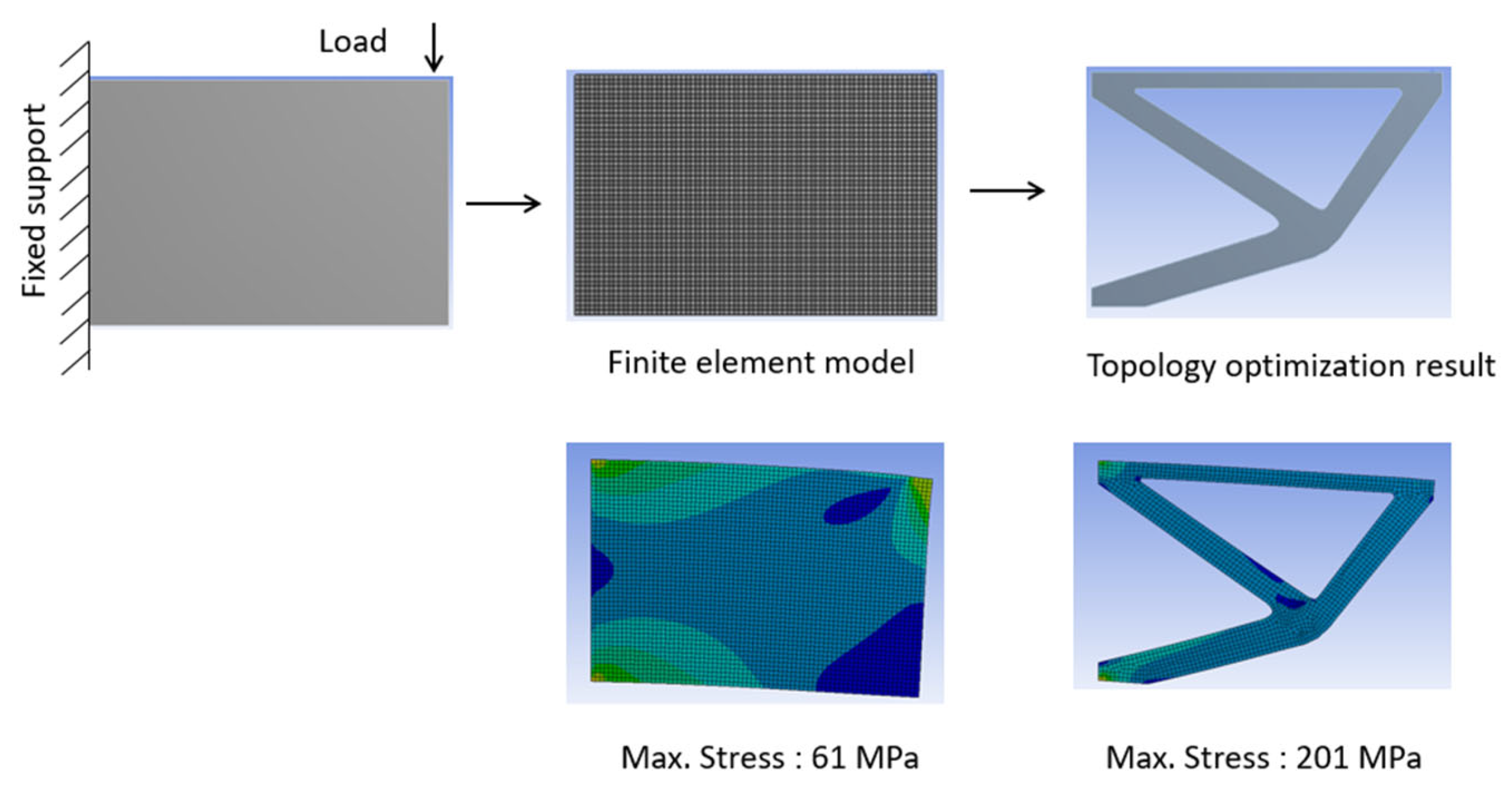
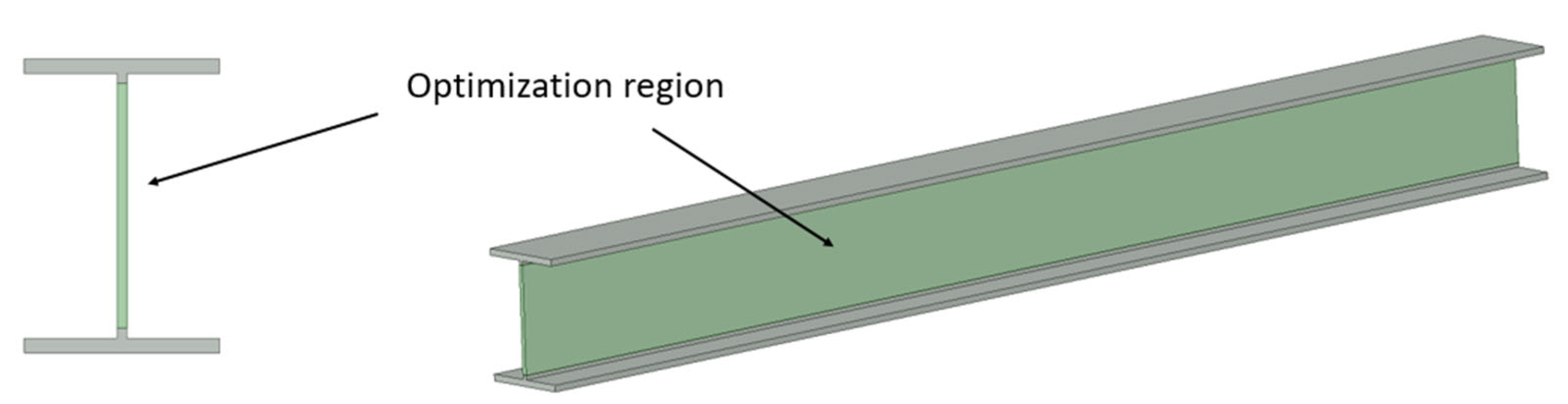
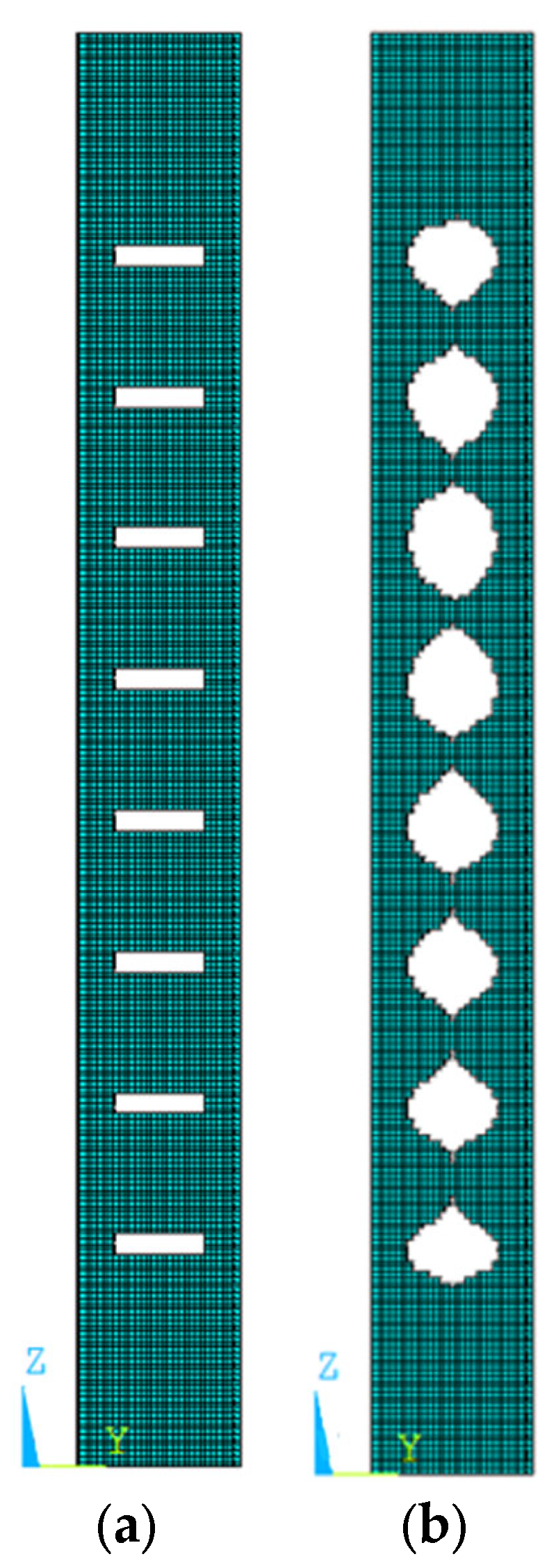
2.1. Optimum Design of the Steel Profile via Topology Optimization

The aim of optimum design is to use less material and prove a more rigid design. In topology optimization, it is aimed at removing inefficient areas, that is, materials with low stress, from the system [16]. Before the optimum design, the boundary and loading conditions of the problem are determined, and then the optimization problem is analyzed. Different objective functions, such as minimizing stress and volume or maximizing stiffness, can be selected depending on structural properties [17]. Topology optimization has been used in many civil engineering problems, such as truss structures, buildings, and reinforced concrete elements [18].
Figure 2 shows an example of a topology optimization application on a cantilever beam. While one end of the cantilever beam was fixed support, a load was applied to the other end. By analyzing the cantilever beam, which was divided into finite elements (meshing), regions with low stress were removed, and the final design was obtained.
The example of a cantilever beam has dimensions of 2000 mm × 3000 mm, and a 350 kN load was applied. The steel material used for cantilever beam has a modulus of elasticity of 2 × 10⁵ and a yield strength of 235 MPa. Also, the finite element model has a 40 mm mesh size, 3750 elements, and 7752 nodes.
In the first case, the cantilever beam does not have any opening, and the maximum stress occurred at 61 MPa. Then, topology optimization was applied, and the material amount of the cantilever beam decreased to nearly 30%. In the new design, a maximum stress of 201 MPa occurred. This example shows the effectiveness of topology optimization with material savings.

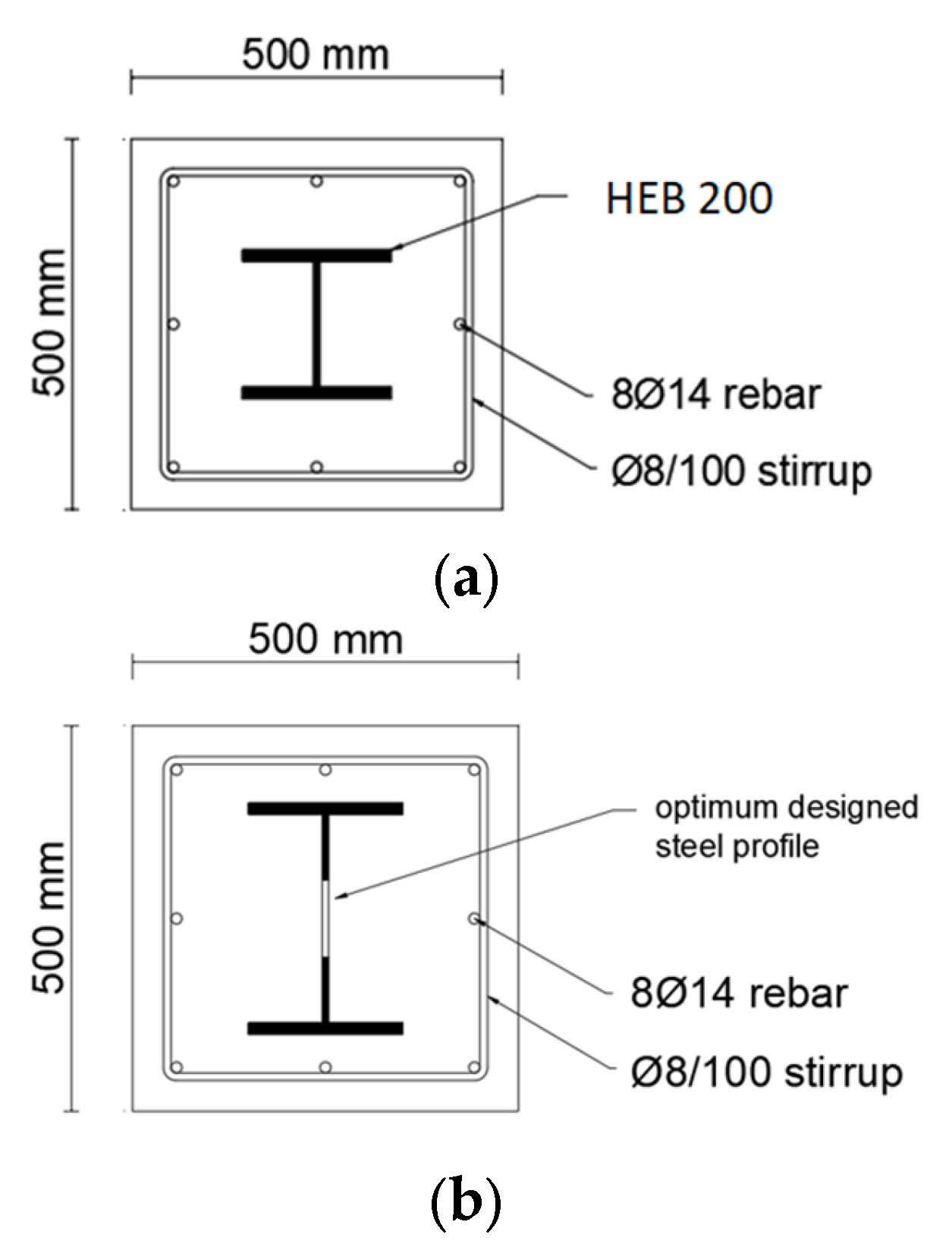
Topology Optimization of the Steel Profile Used in the Composite Column

In this study, linear analysis of a composite column under the influence of axial force and bending moment was performed, and elements with low stress in the steel profile body were removed from the system. Figure 3 shows the steel profile body region where topology optimization was performed. At the beginning of the analysis, successive small initial openings were created in the steel profile body in order to obtain successive opening shapes suitable for production (Figure 4a). As a result of the linear analysis, Von Mises stresses in the steel profile were obtained. Then, the elements with low stress were removed from the steel profile body (Figure 4b). The flowchart of the optimization process can be seen in Figure 5.
The sinusoidal-like opening shapes are arranged as shown in Figure 6 in order to be suitable for production. Figure 7 shows the manufacturing stages of the steel profile with an optimum opening shape. First of all, the steel profile is cut from the body in accordance with the opening shape. Then, the two parts are shifted and welded. This simple manufacturing process increases the moment-bearing capacity of the steel section. The manufacturing process could be undertaken simply by computer numerical control operators.

2.2. Nonlinear Modeling of Concrete-Encased Steel Composite Columns

2.2.1. Verification of Nonlinear Modeling

To verify the nonlinear analyses, an experimental study was analyzed in ANSYS APDL software, and then experimental and numerical studies were compared. There is an experimental study in the literature about concrete-encased steel composite columns [7,19]. In the experimental study, the composite column was designed with cross-sectional dimensions of 170 mm × 220 mm and a height of 2 m. The composite column cross-section and the steel profile dimensions used inside are seen in Figure 8a. While the lower end of the composite column was designed as a fixed support, the upper end was loaded (Figure 8b). In the experimental study, material properties were given as follows: concrete strength as 25.4 MPa, steel profile yield strength as 302 MPa, and reinforcement yield strength as 560 MPa (Table 1). Lateral displacement was applied to a composite column until failure. As seen in the graphs, the results obtained by numerical modeling are very close to the experimental results (Figure 9).

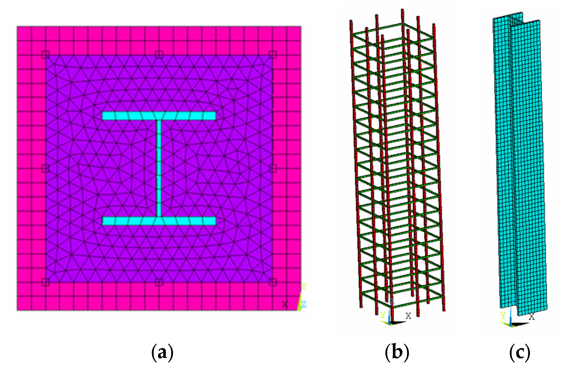
2.2.2. Element Types Used in Composite Column Modeling

ANSYS APDL software was used for analysis [20]. SOLID65 was used to model concrete in the ANSYS program. This element can be used to obtain cracking, crushing, and plastic deformations in three directions. Additionally, this element type provides suitable results for the nonlinear behavior of concrete. The SOLID65 element is defined with 8 node points, and there are three degrees of freedom at each node. SOLID185 was used to model the steel profile in the ANSYS program. This element can make large deformations and take into account the hardening effect. The SOLID185 element is defined with 8 node points, and there are three degrees of freedom at each node. The LINK180 element was used to model longitudinal and transverse reinforcement in the ANSYS program. This element type is defined by two nodes and is used to obtain tensile and compressive stresses. In addition, the LINK180 element can make large deformations and take the hardening effect into account. Modeling made in the ANSYS program can be seen in Figure 10. In the modeling, mesh dimensions were taken as 25 mm. The column base, including all base nodes, is restrained as fixed support.

2.2.3. Material Properties

In the composite column design, two concrete materials, confined and unconfined, are defined for concrete with a compressive strength of 70 MPa (Figure 11). In order to model the concrete material, stress and strain values should be defined. Stress–strain graphs of concrete were obtained with the Mander concrete model defined in TBEC-2018 [21,22]. Additionally, a multilinear isotropic hardening model was used to define the nonlinear modeling of concrete. A multilinear isotropic hardening model was used for defining the stress–strain curve of concrete material.
The material properties of steel profile have a 235 MPa yield strength and a 360 Mpa ultimate strength. Therefore, a biaxial stress–strain curve was defined. For longitudinal reinforcement and stirrups, steel material has a 420 Mpa yield strength and a 550 Mpa ultimate strength. Therefore, a biaxial stress–strain curve was defined. Bilinear isotropic hardening models were used for steel profiles, longitudinal reinforcement, and stirrups.
The William Warnke crack model was used for the nonlinear behavior of concrete. The tensile strength of concrete with a compressive strength of 70 MPa was taken as 7 MPa (10% of the compressive strength). The open crack shear load transmission coefficient was taken as 0.15, and the closed crack shear force load transmission coefficient was taken as 0.90 [23]. These coefficients are defined for shear force load transmission between concrete cracks. The value of the coefficient varies depending on whether the crack is open or closed. Increasing the value of the coefficient shows more shear force load transmission.

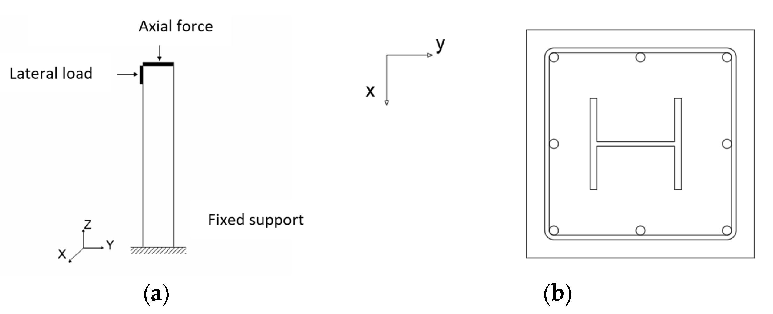
2.2.4. Loading and Boundary Condition

The lower end of the composite column was taken as the fixed support, and the upper end was subjected to constant axial load and lateral displacement (Figure 12). The axial load applied to the column was determined to be 15% of the maximum axial load-carrying capacity of the column. According to the 2018 Turkey Building Earthquake Code (TBEC-2018), the design of columns is made by applying axial force between 10% and 40% [23]. Additionally, there are studies in the literature where the ratio of the applied axial force to the maximum axial load-carrying capacity of the column in experiments on composite columns is taken as 14% [7].

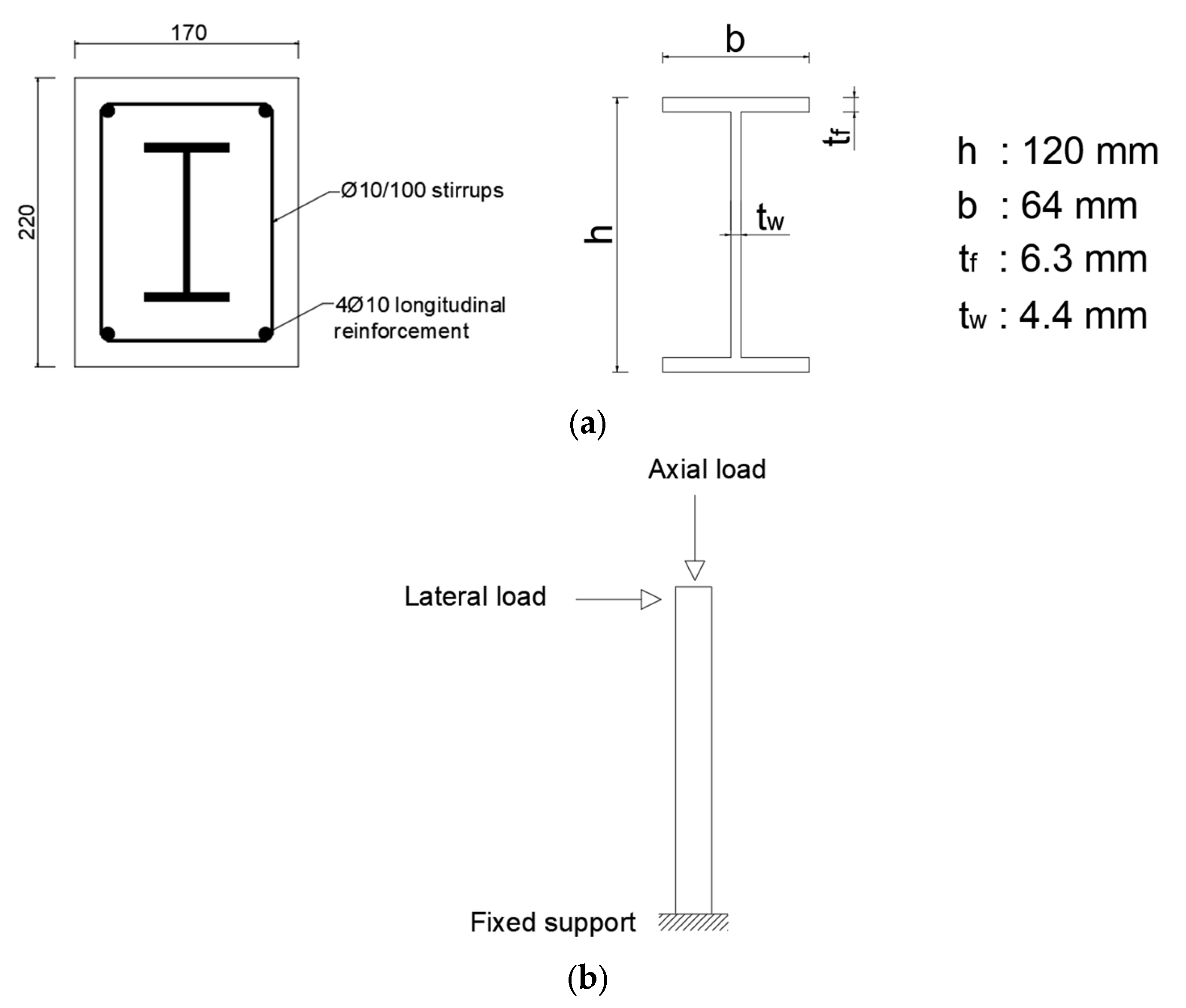
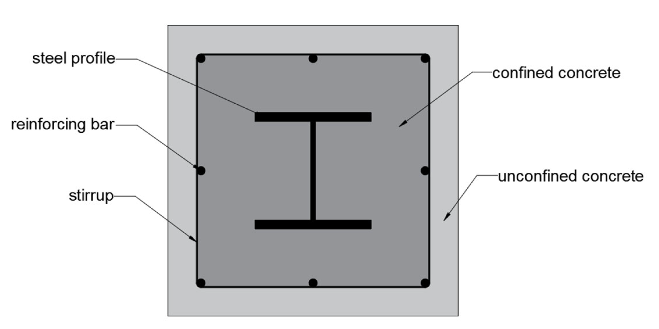
2.2.5. Section Properties

The design of composite columns was made taking into account TBEC-2018 and TSC-2016 regulations. The composite column dimensions were chosen as 500 mm × 500 mm, and the reinforcements are seen in Figure 13. The standard steel profile used in the composite column was chosen as HEB 200 (Figure 13a). After optimum design as a result of topology optimization, the height of the steel profile increased from 200 mm to 300 mm (Figure 13b).

3. Results and Discussions

Numerical analyses were made to compare composite columns with standard and optimally designed steel profiles. As a result of the analysis, load–displacement curves of composite columns were obtained, and they can be seen in Figure 14. While the axial load was kept constant in the analyses, the lateral load was increased from zero to the maximum column-carrying capacity. In both composite column analyses, failure occurred due to the rupture in the longitudinal reinforcement of the columns. As can be seen from the graphics, increasing the height of the steel profile increases the maximum load-carrying capacity of the composite column by 19% and the energy absorption capacity by 24%. Figure 15 shows the von Mises stresses occurring in steel profiles in composite columns before failure.
While the standard steel profile reached a maximum Von Mises stress of 272 MPa before failure, the maximum stress in the optimally designed steel profile increased to 288 MPa. This shows that the optimally designed steel profile works more effectively. The failure of the two composite columns was caused by the breakage of the longitudinal reinforcement. A comparison of composite columns is shown in Table 2.

4. Conclusions

In this study, the aim was to enhance the structural performance of concrete-encased steel composite columns. To achieve this goal, the height of the steel profile used in the composite columns was increased. Topology optimization was employed to determine the optimal opening shapes within the steel profile, resulting in shapes resembling sinusoidal curves. These shapes were adapted for production purposes. Subsequently, a composite column experiment from existing literature was modeled to validate the accuracy of our nonlinear modeling. The load–displacement curves of the experimental and numerical models exhibited remarkable similarity, confirming the precision of our numerical model. Following this validation, a comparison was made between two composite columns: one utilizing a standard steel profile and the other incorporating the optimally designed steel profile. The study’s findings are presented below:
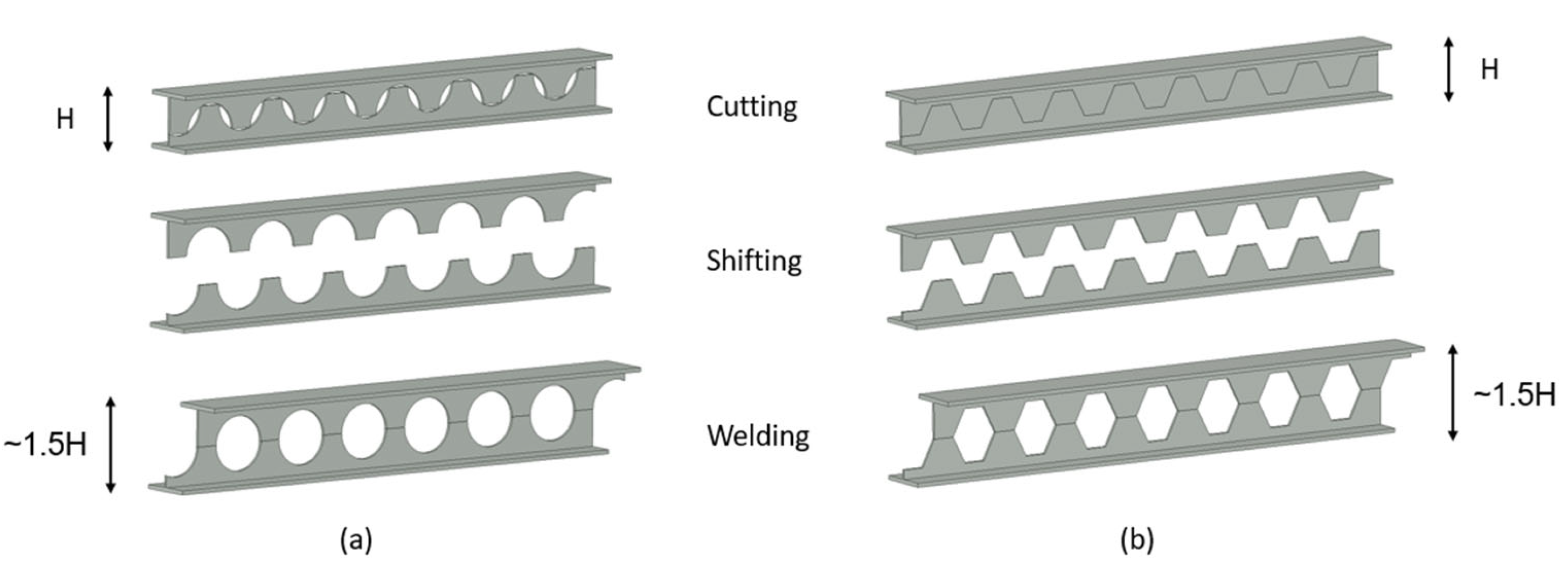
  • To determine the optimal opening shape within the steel profile body, topology optimization was conducted, resulting in shapes resembling sinusoidal curves. The resulting shape was then adapted for production.
  • SOLID65 elements for modeling concrete, SOLID185 for steel profile, and LINK180 for reinforcement were employed in modeling the experiment. The behavior of confined concrete was considered using the Mander model. Additionally, the William Warnke crack model was utilized to describe the nonlinear behavior of concrete, with coefficients of 0.15 for open crack shear load transmission and 0.90 for closed crack shear force transmission. The numerical analyses were validated with experimental results, demonstrating a very close match between the two. As a result, these design parameters can be confidently used for modeling concrete-encased steel composite columns.
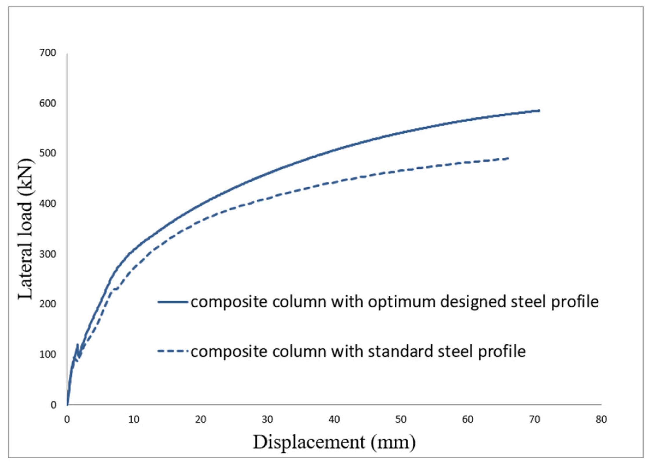
  • As a result of the nonlinear analysis, it was observed that using the optimally designed steel profile in the composite column, instead of the standard steel profile, increased the load-carrying capacity of the composite column by approximately 19%.
  • It was observed that using the optimally designed steel profile in the composite column, instead of the standard steel profile, increased the ductility of the composite column and improved its energy absorption capacity by approximately 24%. Energy absorption capacity was obtained considering the area under load–displacement curves.
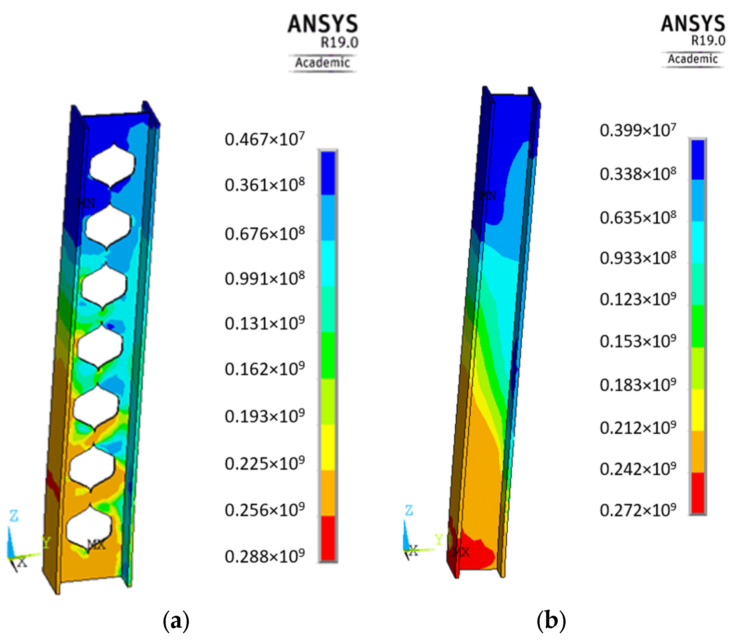
  • The failure of both composite columns was attributed to the rupture of longitudinal reinforcement. The standard steel profile reached a stress of 272 MPa before failure, while the optimally designed steel profile reached 288 MPa before failure. This indicates that the optimally designed steel profile performs more effectively.
Manufacturing and welding operations of the optimally designed steel profile require additional cost and labor. However, the positive effect of increasing the height of the steel section on the composite column’s performance is obvious.
Improving the structural performance of the composite column was achieved with the same amount of material, highlighting the significance of optimal design. Future studies aim to further develop the sinusoidal-like opening shape using various metaheuristic algorithmic methods.

Author Contributions

Conceptualization, E.G.İ. and F.M.Ö.; methodology, E.G.İ. and F.M.Ö.; software, E.G.İ. and F.M.Ö.; validation, E.G.İ. and F.M.Ö.; formal analysis, E.G.İ. and F.M.Ö.; investigation, E.G.İ. and F.M.Ö.; resources, E.G.İ. and F.M.Ö.; writing—original draft preparation, E.G.İ. and F.M.Ö.; writing—review and editing, E.G.İ. and F.M.Ö. All authors have read and agreed to the published version of the manuscript.

Funding

This research received no external funding.

Institutional Review Board Statement

Not applicable.

Informed Consent Statement

Not applicable.

Data Availability Statement

All data and models used during the study appear in the submitted article.

Conflicts of Interest

The authors declare no conflict of interest.

References

  1. Azad, S.; Mirghaderi, S.R.; Epackachi, S. Numerical investigation of steel and composite beam-to-encased composite column connection via a through-plate. Structures 2021, 31, 14–28. [Google Scholar] [CrossRef]
  2. Ren, Q.; Li, M.; Zhang, M.; Shen, Y.; Si, W. Prediction of ultimate axial capacity of square concrete-filled steel tubular short columns using a hybrid intelligent algorithm. Appl. Sci. 2019, 9, 2802. [Google Scholar] [CrossRef]
  3. Thevendran, V.; Shanmugam, N.E.; Chen, S.; Liew, J.R. Experimental study on steel-concrete composite beams curved in plan. Eng. Struct. 2000, 22, 877–889. [Google Scholar] [CrossRef]
  4. Lacki, P.; Derlatka, A.; Kasza, P. Comparison of steel-concrete composite column and steel column. Compos. Struct. 2018, 202, 82–88. [Google Scholar] [CrossRef]
  5. Lai, B.; Liew, J.R.; Wang, T. Buckling behaviour of high strength concrete encased steel composite columns. J. Constr. Steel Res. 2019, 154, 27–42. [Google Scholar] [CrossRef]
  6. Nasery, M.M.; Hüsem, M.; Okur, F.Y.; Altunişik, A.C. Numerical and experimental investigation on dynamic characteristic changes of encased steel profile before and after cyclic loading tests. Int. J. Civil Eng. 2020, 18, 1411–1431. [Google Scholar] [CrossRef]
  7. Campian, C.; Nagy, Z.; Pop, M. Behavior of fully encased steel-concrete composite columns subjected to monotonic and cyclic loading. Procedia Eng. 2015, 117, 439–451. [Google Scholar] [CrossRef]
  8. Lee, C.K.; Khan MK, I.; Zhang, Y.X.; Rana, M.M. Engineered cementitious composites (ECC) encased concrete-steel composite stub columns under concentric compression. Structures 2020, 24, 386–399. [Google Scholar] [CrossRef]
  9. Hoffstaeter, R.A.; Piloto PA, G.; Martins, C.H.; Rigobello, R. Numerical Investigation on the Fire Resistance of Partially Encased Steel Columns. Int. J. Civil Eng. 2023, 21, 1315–1342. [Google Scholar] [CrossRef]
  10. Erdal, F.; Doğan, E.; Saka, M.P. Optimum design of cellular beams using harmony search and particle swarm optimizers. J. Constr. Steel Res. 2011, 67, 237–247. [Google Scholar] [CrossRef]
  11. Durif, S.; Bouchair, A. Analytical model to predict the resistance of cellular beams with sinusoidal openings. J. Constr. Steel Res. 2016, 121, 80–96. [Google Scholar] [CrossRef]
  12. Xue, J.; Zhao, X.; Ke, X.; Zhang, X.; Zhang, F.; Zhang, P. Experimental and numerical investigation of high-strength concrete encased steel columns with rectangular-spiral stirrups. J. Build. Eng. 2020, 32, 101518. [Google Scholar] [CrossRef]
  13. TSC-2016; Türkiye Steel Code. Ministry of Construction and Settlement: Ankara, Turkey, 2016.
  14. Kim, C.S.; Park, H.G.; Chung, K.S.; Choi, I.R. Eccentric axial load testing for concrete-encased steel columns using 800 MPa steel and 100 MPa concrete. J. Struct. Eng. 2012, 138, 1019–1031. [Google Scholar] [CrossRef]
  15. EN 1994-1-1; Eurocode 4: Design of Composite Steel and Concrete Structures—Part 1-1: General Rules and Rules for Buildings. CEN: Brussels, Belgium, 2004.
  16. Özkal, F.M.; Uysal, H. A new performance index formulation aiming to attain fully stressed designs for topology optimization problems. Sci. Res. Essays 2010, 5, 2027–2036. [Google Scholar]
  17. Dangal, B.; Jung, S. The Impact of Additive Manufacturing Constraints and Design Objectives on Structural Topology Optimization. Appl. Sci. 2023, 13, 10161. [Google Scholar] [CrossRef]
  18. Ribeiro, T.P.; Bernardo, L.F.; Andrade, J.M. Topology optimisation in structural steel design for additive manufacturing. Appl. Sci. 2021, 11, 2112. [Google Scholar] [CrossRef]
  19. Aribert, J.M.; Campian, C.; Pacurar, V. Monotonic and cyclic behaviour of fully encased composite columns and dissipative interpretation for seismic design. In Stessa; Routledge: London, UK, 2018; pp. 115–121. [Google Scholar]
  20. ANSYS APDL Version 19.0, Finite Element Analysis Software; ANSYS: Canonsburg PA, USA, 2019.
  21. Mander, J.B.; Priestley, M.J.; Park, R. Theoretical stress-strain model for confined concrete. J. Struct. Eng. 1988, 114, 1804–1826. [Google Scholar] [CrossRef]
  22. TBEC-2018; Türkiye Building Earthquake Specifications. Disaster and Emergency Management Authority: Ankara, Turkey, 2020.
  23. Willam, K.J. Constitutive model for the triaxial behavior of concrete. In IABSE Seminar on Concrete Structure subjected Triaxial Stresses; International Association for Bridge and Structural Engineering: Zurich, Switzerland, 1974; pp. 1–30. [Google Scholar]
Figure 1. Manufacturing of castellated elements: (a) circular opening shape; (b) hexagonal opening shape.
Applsci 14 01170 g001
Figure 2. An example of topology optimization for a cantilever beam.
Applsci 14 01170 g002
Figure 3. Steel profile web used for topology optimization.
Applsci 14 01170 g003
Figure 4. (a) Initial state of the steel profile; (b) optimum opening shapes.
Applsci 14 01170 g004
Figure 5. Flowchart of the optimization.
Applsci 14 01170 g005
Figure 6. Revised opening shape for the manufacturing process.
Applsci 14 01170 g006
Figure 7. Manufacturing process of the optimally designed steel profile: (a) cutting; (b) shifting; (c) welding.
Applsci 14 01170 g007
Figure 8. Experimental study: (a) cross-sectional properties; (b) loading and boundary conditions.
Applsci 14 01170 g008
Figure 9. Comparison of numerical and experimental results.
Applsci 14 01170 g009
Figure 10. Modeling in ANSYS software: (a) column cross-section; (b) longitudinal and transverse reinforcement; (c) steel profile.
Applsci 14 01170 g010
Figure 11. Cross-section of the concrete-encased steel composite column.
Applsci 14 01170 g011
Figure 12. Composite column properties (a) loading and boundary conditions (b) section area.
Applsci 14 01170 g012
Figure 13. Section properties (a) composite column with normal steel profile (b) composite column with optimum designed steel profile.
Applsci 14 01170 g013
Figure 14. Load–displacement curves of composite columns designed with standard steel profiles and optimally designed steel profiles.
Applsci 14 01170 g014
Figure 15. Von Mises stresses of the steel profile in the composite column before failure (unit: N/m2) (a) optimum designed steel profile (b) standard steel profile.
Applsci 14 01170 g015
Table 1. Properties of the experimental study.
Composite Column PropertiesExperiment Data
Column height (m)2.0
Concrete compressive strength (MPa)25.40
Yield strength of steel profile (MPa)302
Yield strength of reinforcement (MPa)560
Table 2. Analysis results of composite columns.
Composite Column with Standard HEB200Composite Column with Optimally Designed Steel ProfileIncrease Amount (%)
Lateral load capacity (kN)49158619
Maximum lateral displacement (mm)67716
Maximum stress in steel profile (MPa)2722886
Disclaimer/Publisher’s Note: The statements, opinions and data contained in all publications are solely those of the individual author(s) and contributor(s) and not of MDPI and/or the editor(s). MDPI and/or the editor(s) disclaim responsibility for any injury to people or property resulting from any ideas, methods, instructions or products referred to in the content.

