
Study on Gas Extraction Technology for Goaf Using L-Shaped Borehole on the Ground
China Coal Research Institute, Beijing 100013, China
Appl. Sci. 2024, 14(4), 1594; https://doi.org/10.3390/app14041594
Submission received: 27 January 2024
/
Revised: 13 February 2024
/
Accepted: 15 February 2024
/
Published: 17 February 2024
(This article belongs to the Special Issue Advanced Methodology and Analysis in Coal Mine Gas Control)
Abstract
:This study aimed to examine gas extraction technology in the goaf of an L-shaped borehole in the mining fissure zone of a short-distance coal seam group. The numerical simulation method was used to analyze the failure law of overlying rock during mining, and a mathematical model was established for gas migration in the mining overburden. Finally, gas extraction tests were performed for the L-shaped borehole in the mining fissure zone. The results showed that as the coal mining project progressed, the damage area of the overlying strata in the goaf became larger, and the plastic damage area of the overlying rock along the strike had a saddle shape, being concave in the middle and convex at both ends. The closer the L-shaped borehole in the mining fissure zone was to the coal seam roof, the greater the amount of air leaking from the working face into the goaf, and the lower the overall gas concentration in the goaf. When the vertical distance of the L-shaped borehole was too high, the ability of the L-shaped borehole to control the gas concentration in the lower goaf was weakened. Moreover, the mining fracture zone was a good space for gas migration and storage. Thus, arranging the L-shaped borehole in this zone can greatly improve the efficiency of borehole gas extraction. According to the overlying rock conditions and mining conditions of Tunlan Mine, the L-shaped borehole was positioned 43 m away from the roof of the coal seam. The extraction rate of the L-shaped borehole reached 9.30 m3∙min−1, and the gas concentration in the corners of the working face was kept below 0.4%, yielding an excellent extraction effect.
1. Introduction
Coal is China’s main energy source, accounting for 54.5% of the country’s total primary energy consumption in 2022 [1]. With its economic development, China’s demand for coal is also growing stronger, and the intensity and depth of coal mining are also increasing [2,3]. Mine gas is one of the important factors restricting efficient coal production. Especially with the increase in mining intensity and gas content in coal seams, a large amount of gas emission accompanies the coal mining process. If it is not controlled, it will cause gas explosions in the working face [4,5]. At this stage, most mines can no longer effectively control mine gas only through ventilation, so the method of goaf drainage has been widely used [6,7,8].
At present, there are various methods for gas drainage in goafs, among which underground borehole and gas drainage by buried pipes in goafs are often considered as the simplest methods [9]. Xu et al. achieved efficient gas drainage in the goaf of Pingshu Coal Mine by optimizing the location of the low-level roadway [10]. Chai et al. took Tingnan Coal Mine as their research background and explored the rational layout of the high-level drainage roadway on the roof of the working face and its drainage effect through theoretical analysis, fluent numerical simulation, on-site verification, and other methods [11]. Lei used field experiments to verify the effectiveness of large-diameter boreholes in reducing gas concentration in a goaf and the upper corner [12]. Wang et al. studied the gas production data from vertical boreholes in Australia and conducted a detailed analysis of the correlation between suction pressure, total flow rate, gas flow rate, and air leakage rate as the spacing between boreholes changed [13]. Qu et al. conducted research on gas drainage data from directional boreholes in a goaf, analyzing the technical advantages of this method compared to vertical boreholes drilled from the surface [14].
To improve the efficiency of gas drainage a goaf, it is necessary to further clarify the laws of fractures and damage in the overlying strata of the goaf, as well as the migration patterns of gas in the goaf [15,16]. After mining a coal seam, the layer-separated cracks and break-through cracks in the overlying strata become connected to each other, forming a mining crack zone that changes dynamically [17,18]. This zone provides a channel and space for pressure-relief gas flow and storage in the coal seam or in adjacent coal strata. Extracting the gas in a fracture zone during mining can greatly improve the gas drainage efficiency [19]. Dou et al. analyzed the transfer of elastic energy in a coal seam roof under varying conditions and revealed the development characteristics of fractures [20]. Liu et al. introduced the Sigmoid function to establish a more accurate porosity model based on the theory of overlying strata movement, reflecting the distribution characteristics of the “three horizontal zones” in a goaf, and developed a model for measuring porosity in the goaf [19]. Wang et al. used PFC software to establish a three-dimensional single working-face model and calculated the distribution of porosity values in the overlying strata [21]. Tian et al. employed theoretical analysis, numerical simulation, and formula-fitting methods to obtain the distribution law of porosity in the overlying strata of fully mechanized caving mining under different types of coal pillars in various sections [22].
The study of gas distribution patterns in goafs has significant implications for gas control measures in such regions. Qin et al. employed CFD simulations to elucidate the impact of gas release characteristics from gas sources and the positioning of drainage boreholes on the distribution and migration patterns of gas in a goaf [23]. Rao et al. utilized a combination of numerical simulations and field tests to investigate the gas migration characteristics in the goaf of longwall mining faces [24]. Zhang et al. introduced gas state equations, continuity equations, momentum equations, porosity evolution equations, and permeability evolution equations to simulate gas concentration fields under natural conditions and during gas drainage in a goaf [25]. Li et al. examined the accumulation patterns of gas in a goaf, considering factors such as desorption from residual coal and gas emission from upper adjacent layers [26]. Zhou et al. established a three-dimensional gas distribution model for a goaf, analyzing the influence of pipe spacing and drainage negative pressure on gas distribution in the mined-out area [27]. Li et al. used numerical simulations and air fluid mechanics to analyze the gas behavior in a goaf; the authors calculated the minimum induced air volume and distributed air volume required for the safe production of a tailings roadway [28]. Zhang et al. developed a simplified three-dimensional engineering model of a fracture field based on simulations, and they also simulated the distribution law of the pressure relief gas in a goaf using a high-extraction roadway [15]. Yu et al. conducted “U” and “U + I” ventilation tests on a three-dimensional, fully mechanized caving face simulation platform. The distribution law of the gob pressure field and gas concentration field was obtained [16]. The literature does not currently contain any systematic research on gas drainage technology for the goaf of an L-shaped borehole in the mining fissure zone of a short-distance coal seam. Thus, in this study, I used numerical simulations to investigate the failure characteristics of the overlying strata of a short-distance coal seam group, analyzed the gas extraction effect of the L-shaped borehole goaf in different layers, and performed practical engineering tests to verify the technical advantages of an L-shaped borehole in the mining of a fissure zone.
2. Overview of Mining Area
The Xishan mining area is located in the central part of Shanxi Province and is currently the largest coking coal production base in China. The coal seam has a widely varying buried depth and contains an uneven gas volume. The distance between minable coal seams in the same coal group is close, generally within 10 m. When production activities are ongoing in the mining layer, a significant amount of gas is emitted from the upper and lower adjacent layers, and a string of mutual interference occurs. To study the gas extraction technology in the goaf of an L-shaped borehole in the mining fracture zone of a short-distance coal seam group, the gas extraction in the goaf of the L-shaped borehole in the mining fracture zone of the 12507 working face in Tunlan Mine, Xishan mining area, was used as our research background. The 12507 working face of Tunlan Mine is located in the southern five-pan area of Tunlan Mine (Figure 1). The main coal seams are the 2# and 3# coal seams. The average mining thickness is 4.57 m, the strike length is 806 m, and the inclination length is 220 m. The mine uses a full-height mining method, and the roof is managed using the full caving method.
3. Study on the Failure Law of Mining Overburden
To analyze the evolution law of the mining overburden stress field in the 12507 working face of Tunlan Mine, COMSOL Multiphysics 3.5 software was used to establish a three-dimensional digital simulation model. The size of the model was 400 m × 400 m × 150 m (Figure 2). The action of part of the overburden was equivalent to a uniformly distributed load of 10 MPa. The physical and mechanical parameters of each rock formation in the model are shown in Table 1.
As illustrated in Figure 3, the roof failure of the working face begins as shear failure, whereby cracks are developed in the roof. Then, the failure develops into tensile failure, and fracture or caving finally occurs. The top to the bottom of the coal seam roof contains a tensile failure area, a shear failure area, and an undamaged area. As the working face advances, the tensile failure area gradually increases, and the upper shear failure area also expands; this phenomenon is more obvious when the key layer is broken. The rock stratum in the mining fracture zone is in a plastic failure state, and the mining fracture is developed in this state. Above the mining fracture zone and up to the bedrock surface, the rock stratum is basically undamaged. At the edge of the goaf, because of the boundary coal pillars, the rock mass is in the tensile and compressive stress zones, the mining faults are fully developed, and the plastic zone develops the most. These phenomena form a saddle-shaped distribution pattern with high convexity at both ends and low concavity in the middle. When the working face is mined up to 180 m, the failure height of the plastic zone reaches 55 m on the roof of the coal seam.
4. Numerical Simulation Study on Gas Extraction of L-Shaped Borehole in Mining Fissure Zone
After the coal seam is mined, the separation fractures in the overburden layer are connected to fractures in the through layer to form a dynamic mining fissure zone. This area provides channels and spaces for the flow and storage of the pressure-relieved gas in the coal seam or adjacent coal seams, and the gas migration is very complex. In this chapter, a gas migration model for the mining overburden is established, the gas migration law in the mining fracture field is examined, the gas drainage effect of the L-shaped borehole in different layers is analyzed, and a reasonable location for the L-shaped borehole is determined.
4.1. Mathematical Model of Gas Migration in Mining Overburden
4.1.1. Gas Transport Equation
The gas flow in the roadway and working face can be equivalent to the fluid flow in the pipeline. The Navier–Stokes equation is used to describe the gas flow state in the working face and roadway.
where η is the gas flow viscosity coefficient, kg/(m⋅s); μ is the fluid flow velocity, m/s; ρ is the fluid density, kg/m3; and p is the fluid pressure, MPa.
4.1.2. Gas Flow Equation in the Goaf
After the coal seam is mined, the overlying roof is broken, filling the entire goaf. Additionally, several voids are formed within the gangue, resulting in a porous-medium structure. Therefore, the Brinkman equation is used to describe the gas flow in the goaf:
where ε is porosity, and k is permeability, m2.
4.1.3. Gas Diffusion Equation
The gas in the goaf obeys the dispersion law and the diffusion law. However, none of the above equations reflect the gas diffusion and migration; hence, it is necessary to use the flow–diffusion equation for a supplementary description:
where θs is the gas volume fraction; c is the gas concentration, mol/m3; DL is the gas pressure diffusion tensor, m2/d; and SC is the gas source.
4.2. Physical Model Building
According to the actual situation of the working face, a physical model of the L-shaped well gas extraction in the mining fissure zone was established (Figure 4). The size of the goaf model was 300 m × 220 m × 60 m, the size of the working face was 5 m × 220 m × 3.5 m, and the dimensions of the two tunnels were 20 m × 4.5 m × 3.5 m. The diameter of the L-shaped borehole was 0.1714 m. To analyze the extraction effect of the L-shaped borehole at different positions, the drilling positions were set at 23 m, 33 m, 43 m, and 53 m from the roof of the coal seam, respectively.
According to the above research on the stress and damage law of the mining overburden, the overburden strata in the goaf caved and an O-type rupture occurred while the working face advanced. The mining fissures and free caving rocks in the middle of the goaf were basically compacted, and the coal-pillar-side separation fissures and caving fissures around the goaf remained. The distribution of the caving dilatation coefficient in the goaf is described by the following expression (the initial caving dilatation coefficient of the roof is taken to be 1.6, and the compacted dilatation coefficient is taken to be 1.1):
where K(x,y) is the caving and fragmentation coefficient of the goaf; Kmax is the crushing expansion coefficient of the initial caving; Kmin is the crushing expansion coefficient after compaction; m0 and m1 are the attenuation rates from the solid wall and the working face, respectively; d0 and d1 are the distances from the point (x, y) to the working face boundary and solid wall, m.
The specific values can be obtained through a trial-and-error calculation. Assuming m1 = 0.0368, m0 = 0.268, and ξ = 0.233, the K(x,y) distribution results are illustrated in Figure 4.
The position of the air inlet was set as the inlet boundary, and the inlet boundary contained the wind speed and gas concentration values. According to the actual situation of the working face, the airflow speed of the air inlet was set to 2.2 m/s, and the gas concentration was 0, that is, the incoming fresh airflow was considered to not contain any gases. According to the calculation process of the field test data of Tunlan Mine, the gas emission from the coal wall of the working face was set at 7.48 × 10⁻⁵ kg/(m3·s), and the gas emission from the residual coal in the goaf was set at 7.48 × 10⁻⁵ kg/(m3·s); the suction pressure of L-shaped borehole drainage was 50 kPa.
As shown in Figure 5, as the vertical distance increases, the gas concentration in the upper corners first decreases, and then, increases, indicating that when the vertical distance parameter of the ground L-shaped borehole is within a certain range, the ground L-shaped borehole is extracted from the goaf. A gas with a higher concentration was generated, and the gas concentration at the points investigated in the goaf was reduced to varying degrees. When the vertical distance of the local L-shaped borehole is too high, the ground L-shaped borehole has a weakened ability to control the gas concentration in the lower goaf. Although the ground L-shaped borehole can extract the gas with a higher concentration in the goaf, it has little impact on the change in the gas concentration near the upper corner. When the vertical distance reaches 53 m, the gas concentration in the upper corner reaches 1.2%. In summary, the L-shaped borehole in the mining fissure zone of the 12507 working face of Tunlan Mine should be located at about 43 m from the roof of the coal seam.
5. Analysis of Gas Extraction Effect in Goaf of L-Shaped Borehole in Mining Fissure Zone
Considering the development law of the 12507 working face mining overburden fissure, the gas migration law in the goaf under the action of the L-shaped borehole in the mining fissure zone, the actual gas control situation in the Tunlan Mine goaf, and the repeated on-site field explorations, we recommend that the location of the L-shaped borehole in the mining fissure zone that should be selected is that west of Dupo Village, Gujiao City. This location corresponds to the surface of the 12507 working face (X: 4,193,380.212, Y: 37,596,000.438, H: 1212.894). The terrain is relatively flat, and the traffic is relatively moderate, which is convenient for construction, transportation, and subsequent gas extraction. The vertical depth of the borehole is 502.00 m, the well depth is 1117.16 m, the plane projection distance from the orifice to the target point is 724.62 m, the landing point is 48.30 m on the 2# coal roof, and the target point is 38.19 m on the 2# coal roof (Figure 6 and Figure 7).
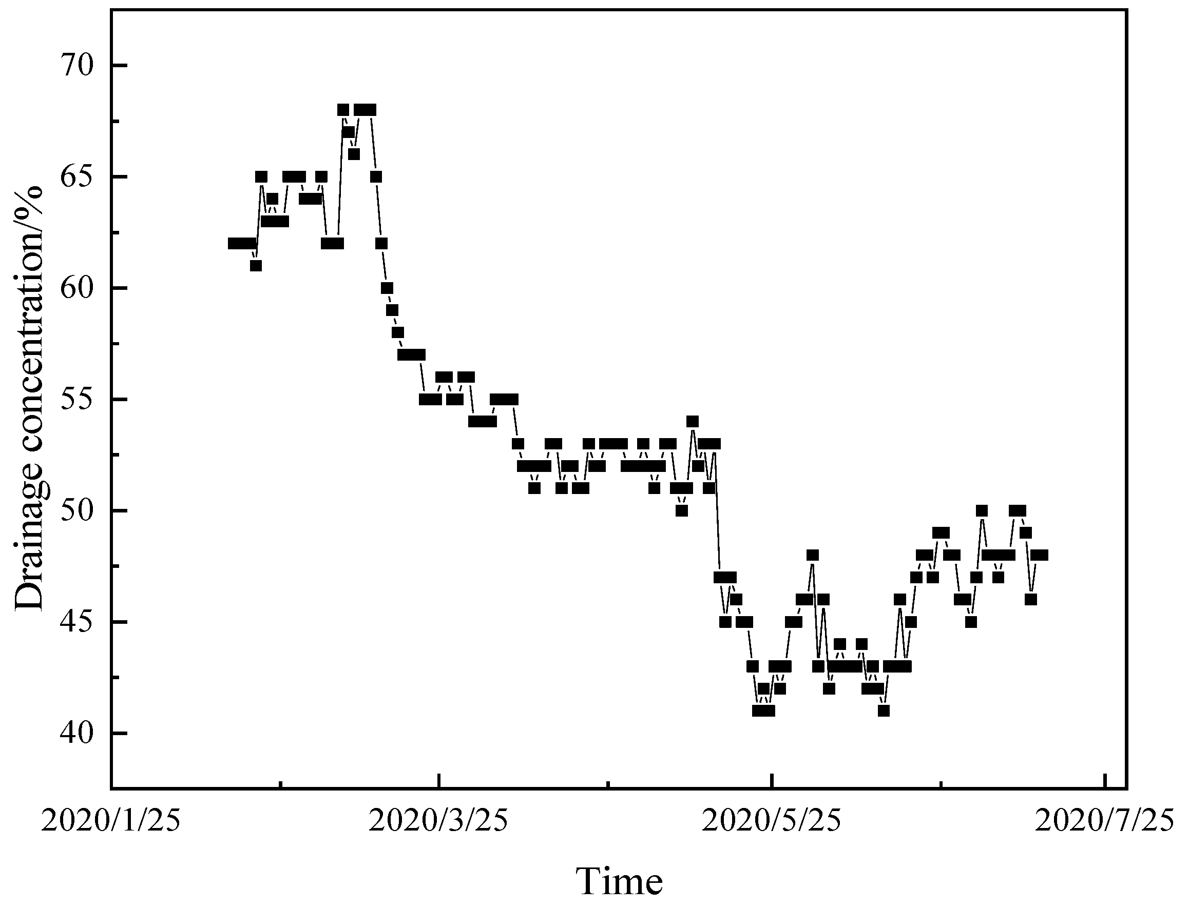
Figure 8 and Figure 9 show the variation law of the gas production rate, cumulative production, and extraction concentration of the L-shaped borehole in the mining fissure zone. According to downhole monitoring, on 17 February, the roof collapsed across a large area, the overlying stratum fissures in the goaf were connected, and the L-shaped borehole on the ground in the mining fissure zone began to emit gas. After 149 days of production, the cumulative production reached 2,009,318 m3. The gas production rate and concentration of the boreholes were unstable, exhibiting an increase–decrease–increase cycle. This is because the lithology of the coal seam roof is complex, and the degree of continuity of the overlying fissures varies with position. The gas production rate and the extraction concentration of the L-shaped borehole in the fissure zone during the mining stage were high, with average values of 9.30 m3∙min−1 and 53.20%, respectively. These values are considered to indicate an excellent extraction effect.
6. Conclusions
(1) As coal mining progresses, the damage area of the overlying strata in the goaf enlarges, and the plastic damage area of the overlying rock along the strike takes the shape of a saddle that is concave in the middle and convex at both ends
(2) The closer the L-shaped borehole in the mining fissure zone is to the coal seam roof, the greater the amount of air leaking from the working face into the goaf, and the overall gas concentration in the goaf becomes relatively lower. When the vertical distance of the L-shaped borehole is too high, the L-shaped borehole has a weakened ability to control the gas concentration in the lower goaf.
(3) The mining fracture zone is a good space for gas migration and storage. Setting the L-shaped borehole in this position can greatly improve the efficiency of the borehole gas extraction. According to the overlying rock and mining conditions of Tunlan Mine, the L-shaped borehole is positioned 43 m away from the roof of the coal seam. The extraction rate of the L-shaped borehole can reach 9.30 m3∙min−1, and the gas concentration in the corners of the working face is kept below 0.4%, which indicates an excellent extraction effect.
Funding
This study was supported by the China Coal Research Institute Technology Innovation Fund (2022CX-I-05).
Institutional Review Board Statement
Not applicable.
Informed Consent Statement
Not applicable.
Data Availability Statement
The data presented in this study are available on request from the corresponding author. The data are not publicly available due to containing information that could compromise the privacy of research participants.
Conflicts of Interest
The author declare no conflict of interest. The funders had no role in the design of the study; in the collection, analyses, or interpretation of the data; in the writing of the manuscript; or in the decision to publish the results.
References
- Kao, X.; Wang, W.; Zhu, X.; Zhang, J. Spatial and Temporal Characteristics of Coal Consumption and Carbon Emissions in China. Environ. Sci. Pollut. Res. 2023, 30, 105770–105780. [Google Scholar] [CrossRef]
- Fan, Y.; Deng, C.; Zhang, X.; Li, F.; Wang, X.; Qiao, L. Numerical Study of CO2-Enhanced Coalbed Methane Recovery. Int. J. Greenh. Gas Control 2018, 76, 12–23. [Google Scholar] [CrossRef]
- Shu, L.; Wang, K.; Liu, Z.; Zhao, W.; Zhu, N.; Lei, Y. A Novel Physical Model of Coal and Gas Outbursts Mechanism: Insights into the Process and Initiation Criterion of Outbursts. Fuel 2022, 323, 124305. [Google Scholar] [CrossRef]
- Gao, A.; Qin, B.; Zhang, L.; Ma, D.; Li, L. Experimental Study on Gas Migration Laws at Return Air Side of Goaf under High-Temperature Conditions. Combust. Sci. Technol. 2023, 195, 1930–1944. [Google Scholar] [CrossRef]
- Ren, T.X.; Balusu, R. Proactive Goaf Inertisation for Controlling Longwall Goaf Heatings. Procedia Earth Planet. Sci. 2009, 1, 309–315. [Google Scholar] [CrossRef]
- Wang, Y.; Si, G.; Oh, J.; Belle, B. CFD Modelling of Longwall Goaf Atmosphere under Vertical Boreholes Gas Drainage. Int. J. Coal Geol. 2023, 280, 104400. [Google Scholar] [CrossRef]
- Si, G.; Belle, B. Performance Analysis of Vertical Goaf Gas Drainage Holes Using Gas Indicators in Australian Coal Mines. Int. J. Coal Geol. 2019, 216, 103301. [Google Scholar] [CrossRef]
- Ma, Q.; Xue, J.; Shi, Y.; Zeng, X. Characteristics of Porosity Distribution and Gas Migration in Different Layers of Comprehensive Working Face Goaf. Energies 2023, 16, 2325. [Google Scholar] [CrossRef]
- Zhou, F.; Xia, T.; Wang, X.; Zhang, Y.; Sun, Y.; Liu, J. Recent Developments in Coal Mine Methane Extraction and Utilization in China: A Review. J. Nat. Gas Sci. Eng. 2016, 31, 437–458. [Google Scholar] [CrossRef]
- Xu, C.; Wang, K.; Li, X.; Yuan, L.; Zhao, C.; Guo, H. Collaborative Gas Drainage Technology of High and Low Level Roadways in Highly-Gassy Coal Seam Mining. Fuel 2022, 323, 124325. [Google Scholar] [CrossRef]
- Chai, J. Study on Gas Control in Goaf of High Gas Coal Seam: A Case Study of Tingnan Coal Mine, China. Geofluids 2022, 2022, 5262173. [Google Scholar] [CrossRef]
- Lei, Y. Movement Law of Methane Drained by Large-Diameter Borehole Drilling Machine in the Goaf. Processes 2022, 10, 1669. [Google Scholar] [CrossRef]
- Wang, Y.; Si, G.; Xiang, Z.; Oh, J.; Belle, B.; Webb, D. A Theoretical Goaf Resistance Model Based on Gas Production Analysis in Goaf Gas Drainage. Int. J. Coal Geol. 2022, 264, 104140. [Google Scholar] [CrossRef]
- Qu, Q.; Guo, H.; Loney, M. Analysis of Longwall Goaf Gas Drainage Trials with Surface Directional Boreholes. Int. J. Coal Geol. 2016, 156, 59–73. [Google Scholar] [CrossRef]
- Zhang, M.; Wu, S.; Wang, Y. Research and Application of Drainage Parameters for Gas Accumulation Zone in Overlying Strata of Goaf Area. Saf. Sci. 2012, 50, 778–782. [Google Scholar] [CrossRef]
- Yu, Z.; Yang, S.; Qin, Y.; Hu, X.; Cheng, J. Experimental Study on the Goaf Flow Field of the “U + I” Type Ventilation System for a Comprehensive Mechanized Mining Face. Int. J. Min. Sci. Technol. 2015, 25, 1003–1010. [Google Scholar] [CrossRef]
- Xie, J.; Zhao, Y. A Mathematical Model to Study the Coupling Effect of Deformation-Seepage-Heat Transfer on Coalbed Methane Transport and Its Simulative Application. Math. Probl. Eng. 2020, 2020, 1247240. [Google Scholar] [CrossRef]
- Yang, H.; Liu, Z.; Zhu, D.; Yang, W.; Zhao, D.; Wang, W. Study on the Fractal Characteristics of Coal Body Fissure Development and the Law of Coalbed Methane Migration of around the Stope. Geofluids 2020, 2020, 9856904. [Google Scholar] [CrossRef]
- Liu, Q.; Lin, B.; Zhou, Y.; Li, Y. Porosity Model of the Goaf Based on Overlying Strata Movement and Deformation. Environ. Earth Sci. 2022, 81, 214. [Google Scholar] [CrossRef]
- Dou, L.; Yang, K.; Liu, W.; Chi, X. Mining-Induced Stress-Fissure Field Evolution and the Disaster-Causing Mechanism in the High Gas Working Face of the Deep Hard Strata. Geofluids 2020, 2020, 8849666. [Google Scholar] [CrossRef]
- Wang, G.; Xu, H.; Wu, M.; Wang, Y.; Wang, R.; Zhang, X. Porosity Model and Air Leakage Flow Field Simulation of Goaf Based on DEM-CFD. Arab. J. Geosci. 2018, 11, 148. [Google Scholar] [CrossRef]
- Tian, S.; Mao, J.; Li, H. Porosity Distribution Law of Overlying Strata in the Goaf of the Adjacent Working Face: From the Perspective of Section Coal Pillar Types. Minerals 2022, 12, 782. [Google Scholar] [CrossRef]
- Qin, Z.; Yuan, L.; Guo, H.; Qu, Q. Investigation of Longwall Goaf Gas Flows and Borehole Drainage Performance by CFD Simulation. Int. J. Coal Geol. 2015, 150–151, 51–63. [Google Scholar] [CrossRef]
- Balusu, R.; Belle, B.; Tanguturi, K. Development of Goaf Gas Drainage and Inertisation Strategies in 1.0-Km- and 3.0-Km-Long Panels. Min. Metall. Explor. 2019, 36, 1127–1136. [Google Scholar] [CrossRef]
- Zhang, F.; Xu, H.; Qin, Y.; Guo, M.; He, S.; Wang, K.; Shi, Y.; Xiang, Z. Numerical Simulation and Investigation of Methane Gas Distribution and Extraction in Goaf with U-Type Ventilation of Working Face. Environ. Sci. Pollut. Res. 2023, 30, 59510–59527. [Google Scholar] [CrossRef] [PubMed]
- Li, F.; Shang, Y.; Kong, D.; Zhang, G.; Wang, Y.; Wang, Y.; Zhang, Z. Gas Migration Law and Precision Extraction in Close Distance Coal Seam Goaf: A Case Study. Geotech. Geol. Eng. 2023, 41, 3781–3801. [Google Scholar] [CrossRef]
- Zhou, A.; Xu, Z.; Wang, K.; Wang, Y.; An, J.; Shi, Z. Coal Mine Gas Migration Model Establishment and Gas Extraction Technology Field Application Research. Fuel 2023, 349, 128650. [Google Scholar] [CrossRef]
- Li, Z.-X.; Wang, J.-R.; Zhou, X. Numerical Simulation of Gas Drainage during Open Region Movement in Goaf. J. China Univ. Min. Technol. 2004, 33, 74–78. [Google Scholar]
Figure 1.
Working face overview.
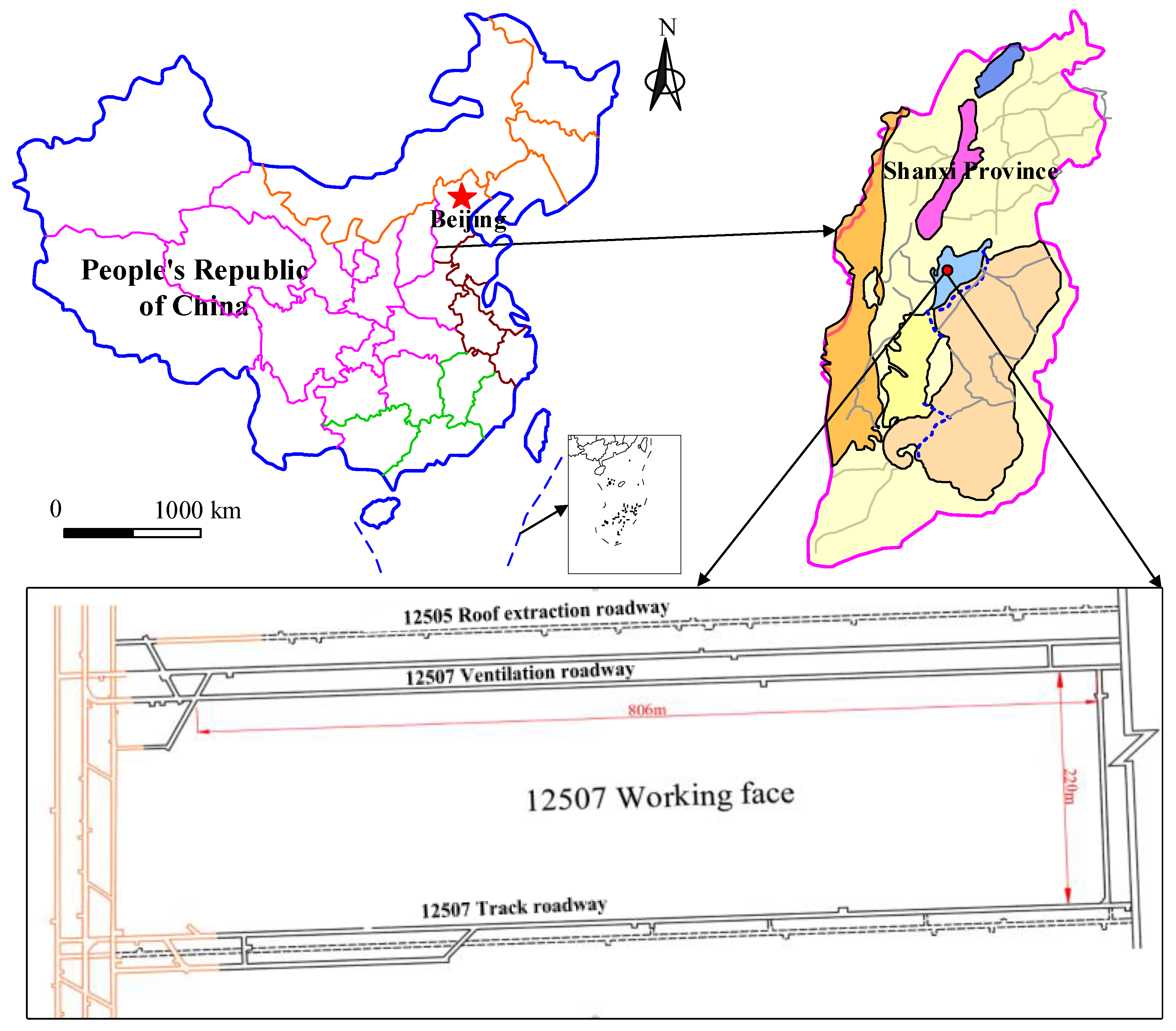
Figure 2.
Numerical simulation model.
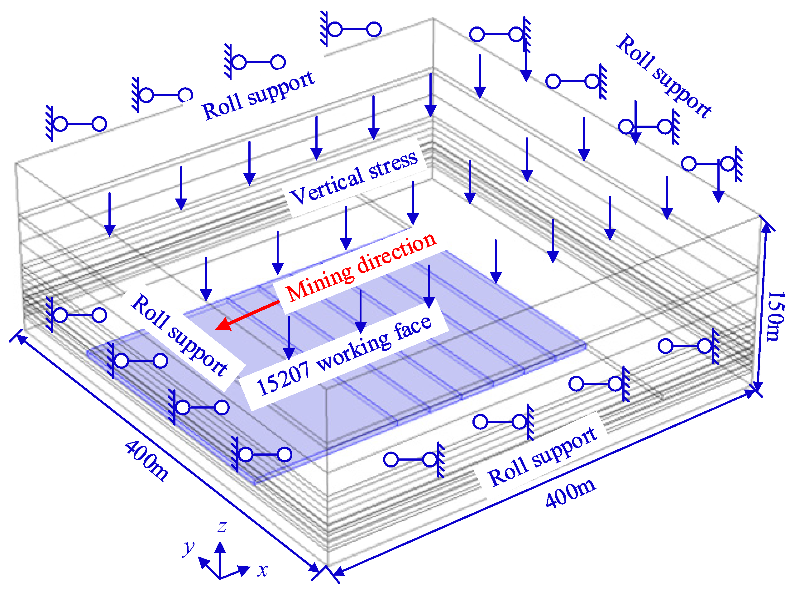
Figure 3.
Distribution of transverse–longitudinal plastic zone at different mining distances: (a) mining distance of 30 m; (b) mining distance of 60 m; (c) mining distance of 90 m; (d) mining distance of 120 m; (e) mining distance of 150 m.
Figure 3.
Distribution of transverse–longitudinal plastic zone at different mining distances: (a) mining distance of 30 m; (b) mining distance of 60 m; (c) mining distance of 90 m; (d) mining distance of 120 m; (e) mining distance of 150 m.
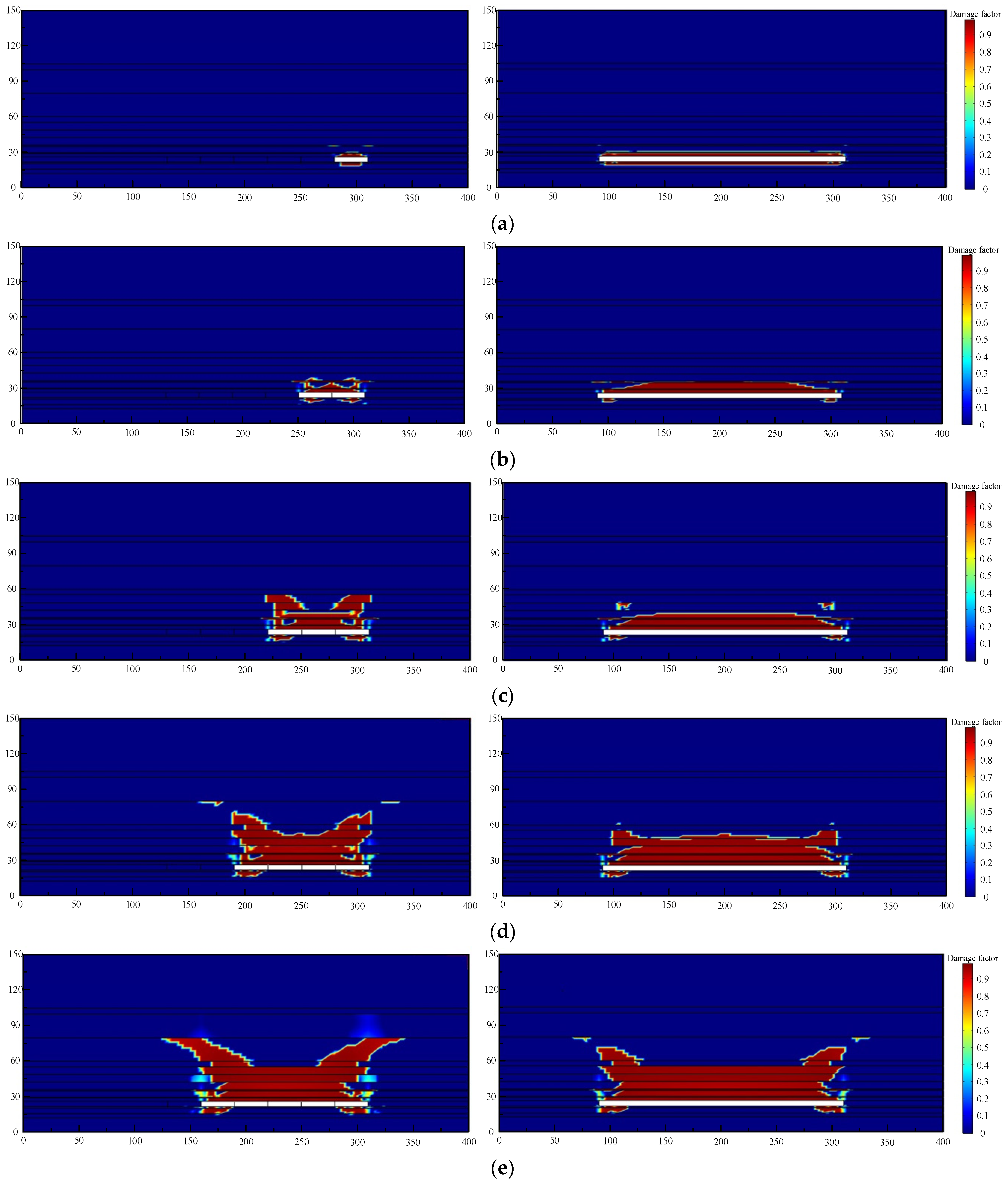
Figure 4.
The physical model of the L-shaped well gas extraction.
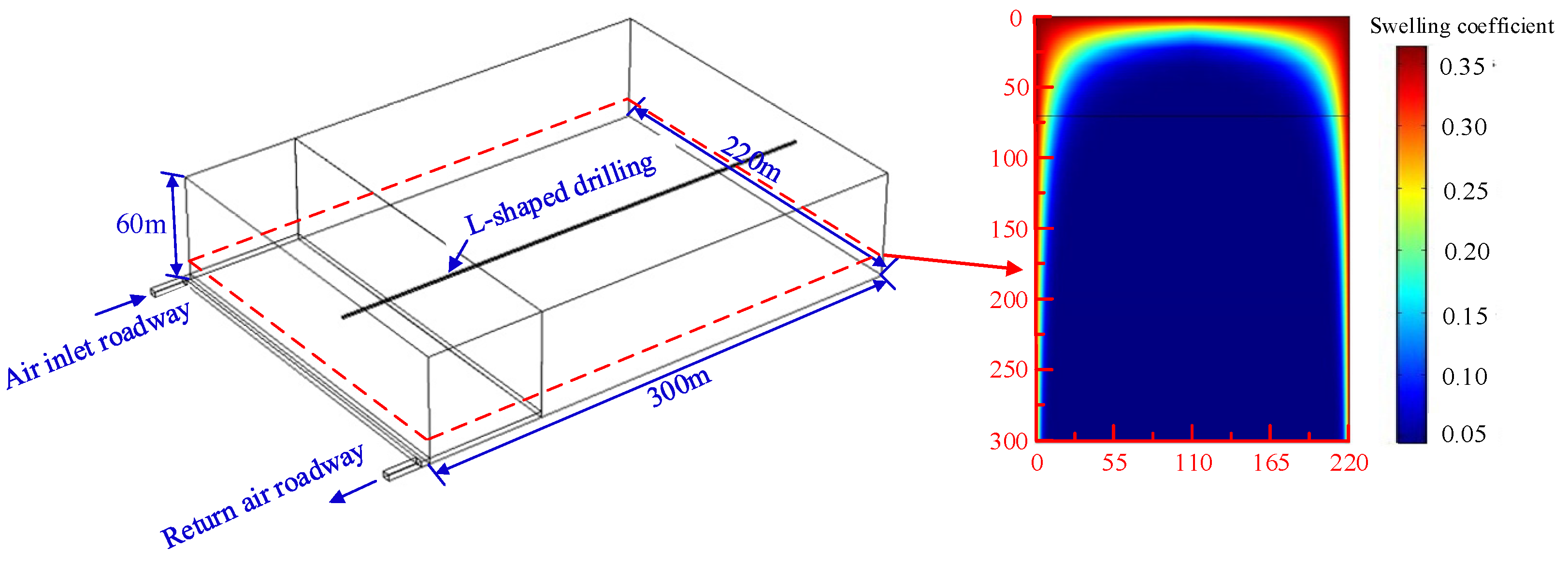
Figure 5.
Distribution of transverse–longitudinal plastic zone at different mining distances: (a) L-shaped borehole 23 m away from coal seam roof; (b) L-shaped borehole 33 m away from coal seam roof; (c) L-shaped borehole 43 m away from coal seam roof; (d) L-shaped borehole 53 m away from coal seam roof.
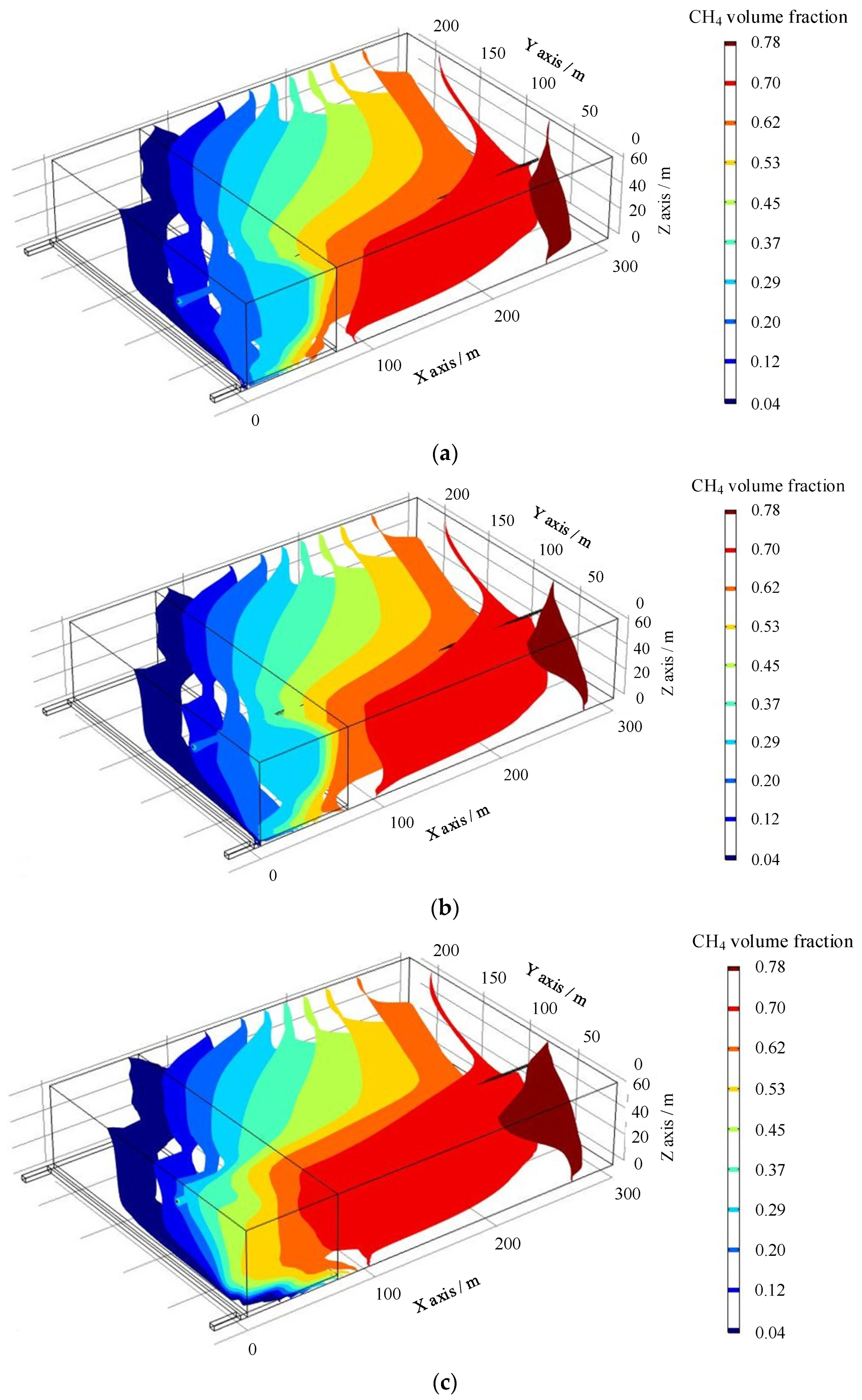
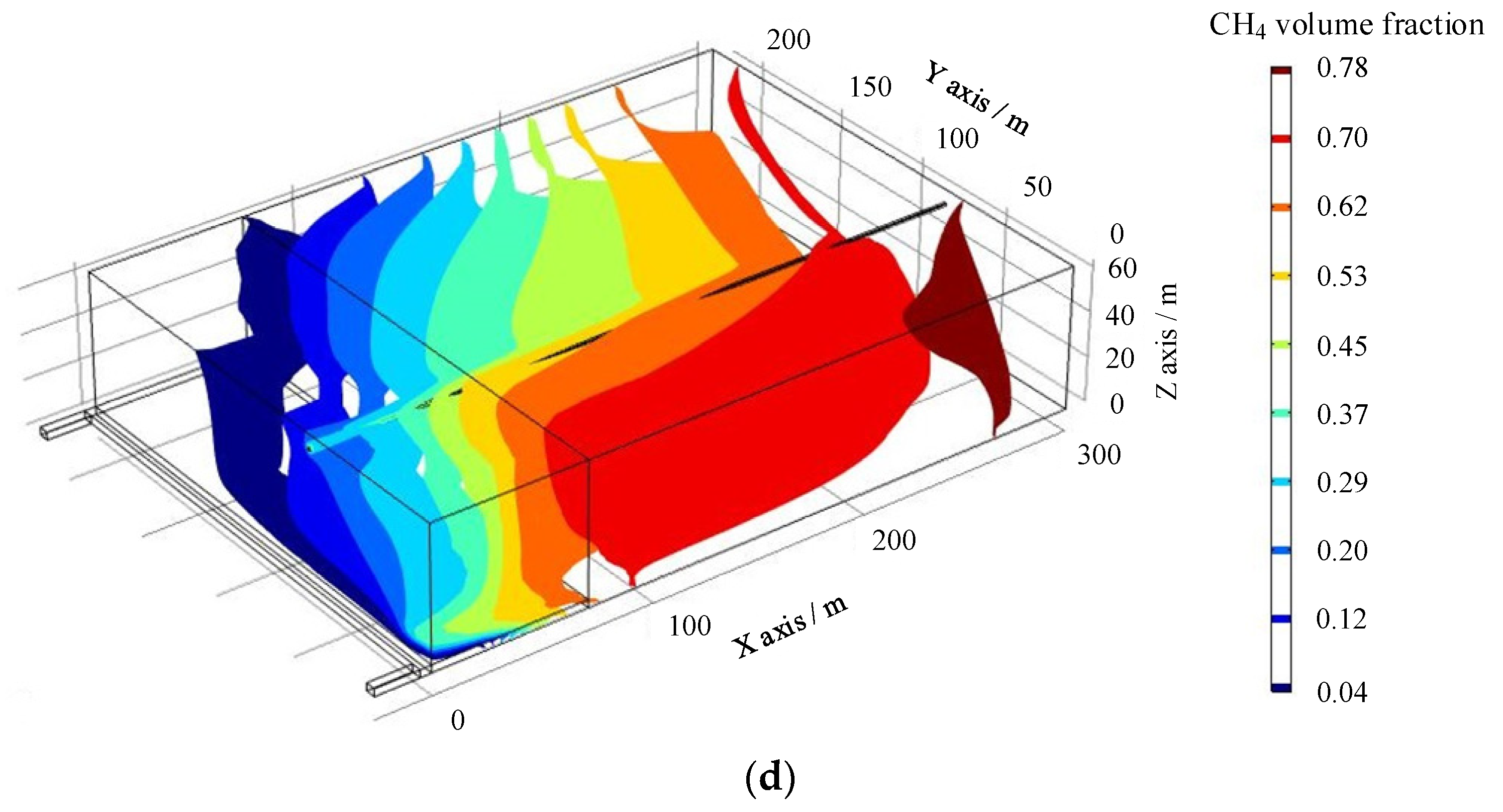
Figure 6.
Upper and lower comparisons of L-shaped drilled wells in mining fracture zone of 12507 working face in Tunlan Mine.
Figure 6.
Upper and lower comparisons of L-shaped drilled wells in mining fracture zone of 12507 working face in Tunlan Mine.
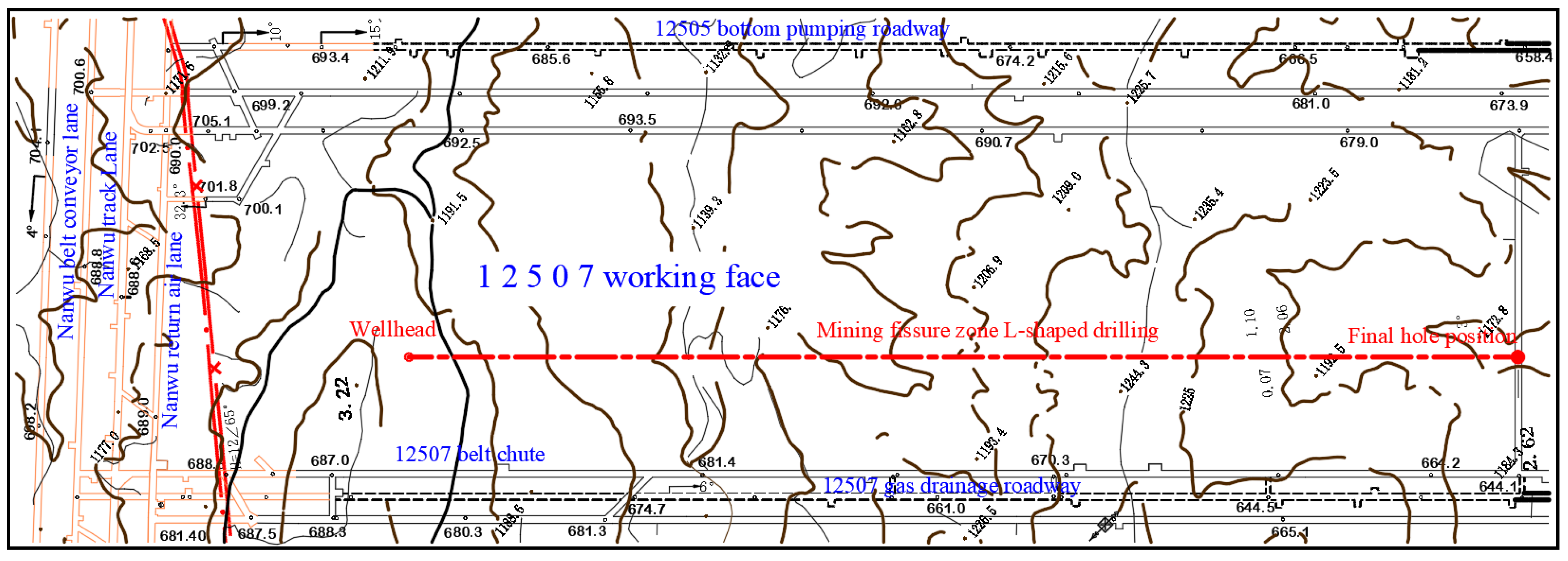
Figure 7.
Sectional view of L-shaped borehole in mining fissure zone of 12507 working face in Tunlan Mine.
Figure 7.
Sectional view of L-shaped borehole in mining fissure zone of 12507 working face in Tunlan Mine.
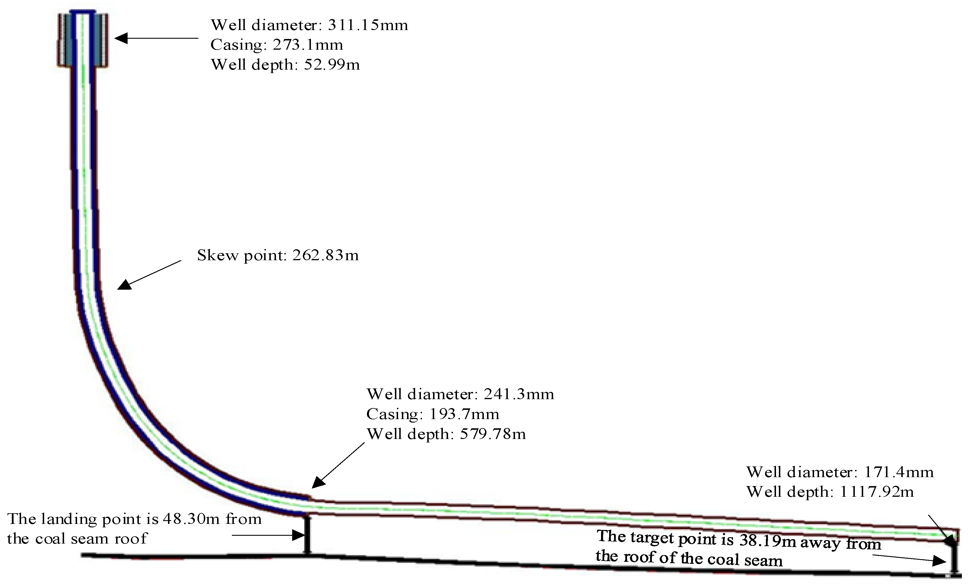
Figure 8.
Gas production rate and cumulative production of L-shaped borehole on ground of mining fissure zone.
Figure 8.
Gas production rate and cumulative production of L-shaped borehole on ground of mining fissure zone.
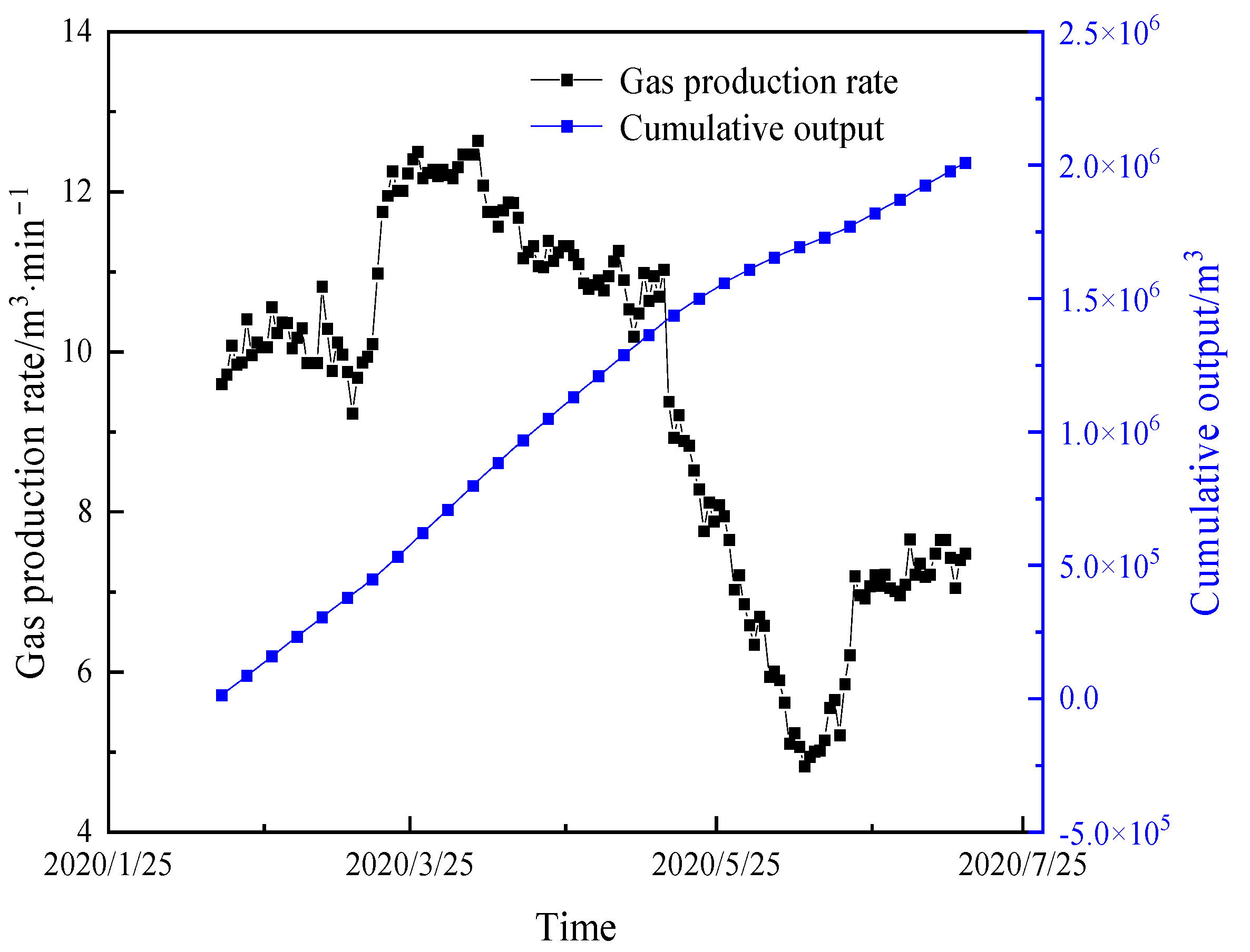
Figure 9.
CBM extraction concentration of surface L-shaped boreholes in mining fissure zone.

Table 1.
Physical and mechanical parameters of each rock formation in the model.
| No. | Lithology | Thickness (m) | Bulk Modulus (MPa) | Poisson’s Ratio | Elastic Modulus (MPa) | Density (kg/m3) | Uniaxial Tensile Strength | Internal Friction Angle | Cohesion (MPa) |
|---|---|---|---|---|---|---|---|---|---|
| 1 | Limestone | 12.39 | 4523 | 0.19 | 8412.78 | 2700 | 4.03 | 42 | 4.8 |
| 2 | Medium-grained sandstone | 3.34 | 3240 | 0.17 | 6415.2 | 2510 | 2.35 | 38 | 4.07 |
| 3 | No. 7 coal seam | 4.57 | 1580 | 0.28 | 2085.6 | 1380 | 0.52 | 30 | 1.42 |
| 3 | Fine-grained sandstone | 4.57 | 4176 | 0.18 | 8017.92 | 2680 | 2.62 | 40 | 4.53 |
| 4 | Sandy mudstone | 1.35 | 2800 | 0.24 | 4368 | 2450 | 1.55 | 35 | 3.61 |
| 5 | No. 2 + 3 coal seam | 4.57 | 1580 | 0.28 | 2085.6 | 1380 | 0.52 | 30 | 1.42 |
| 6 | Fine-grained sandstone | 2.75 | 4176 | 0.18 | 8017.92 | 2680 | 2.62 | 40 | 4.53 |
| 7 | Sandy mudstone | 0.78 | 2800 | 0.24 | 4368 | 2450 | 1.55 | 35 | 3.61 |
| 8 | Siltstone | 5.13 | 2530 | 0.25 | 3795 | 2550 | 1.66 | 36 | 3.3 |
| 9 | No. 4 coal seam | 1.12 | 1580 | 0.28 | 2085.6 | 1380 | 0.52 | 30 | 1.42 |
| 10 | Medium-grained sandstone | 6.46 | 3240 | 0.17 | 6415.2 | 2510 | 2.35 | 38 | 4.07 |
| 11 | Sandy mudstone | 6.27 | 2800 | 0.24 | 4368 | 2450 | 1.55 | 35 | 3.61 |
| 12 | Fine-grained sandstone | 6.75 | 4176 | 0.18 | 8017.92 | 2680 | 2.62 | 40 | 4.53 |
| 13 | Medium-grained sandstone | 4.57 | 3240 | 0.17 | 6415.2 | 2510 | 2.35 | 38 | 4.07 |
| 14 | Fine-grained sandstone | 19.92 | 4176 | 0.18 | 8017.92 | 2680 | 2.62 | 40 | 4.53 |
| 15 | Mudstone | 20 | 2230 | 0.26 | 3211.2 | 2230 | 0.89 | 32 | 2.98 |
| 16 | Fine sandstone | 4.97 | 4176 | 0.18 | 8017.92 | 2680 | 2.62 | 40 | 4.53 |
| 17 | Medium-grained sandstone | 45.06 | 3240 | 0.17 | 6415.2 | 2510 | 2.35 | 38 | 4.07 |
Disclaimer/Publisher’s Note: The statements, opinions and data contained in all publications are solely those of the individual author(s) and contributor(s) and not of MDPI and/or the editor(s). MDPI and/or the editor(s) disclaim responsibility for any injury to people or property resulting from any ideas, methods, instructions or products referred to in the content. |
© 2024 by the author. Licensee MDPI, Basel, Switzerland. This article is an open access article distributed under the terms and conditions of the Creative Commons Attribution (CC BY) license (https://creativecommons.org/licenses/by/4.0/).
Share and Cite
MDPI and ACS Style
Shu, L. Study on Gas Extraction Technology for Goaf Using L-Shaped Borehole on the Ground. Appl. Sci. 2024, 14, 1594. https://doi.org/10.3390/app14041594
AMA Style
Shu L. Study on Gas Extraction Technology for Goaf Using L-Shaped Borehole on the Ground. Applied Sciences. 2024; 14(4):1594. https://doi.org/10.3390/app14041594
Chicago/Turabian StyleShu, Longyong. 2024. "Study on Gas Extraction Technology for Goaf Using L-Shaped Borehole on the Ground" Applied Sciences 14, no. 4: 1594. https://doi.org/10.3390/app14041594
Note that from the first issue of 2016, this journal uses article numbers instead of page numbers. See further details here.