1. Introduction
With the continuous extension of the application scenarios of centrifugal pumps, people have put forward requirements of being able to work under harsh conditions, especially in situations such as high concentrations of acid or alkali, which make plastic centrifugal pumps stand out, and quickly obtain attention and favor from enterprises due to their strong corrosion resistance, light overall weight, and low price advantages. Centrifugal pumps are mechanical devices that use centrifugal force generated by rotating impellers to facilitate fluid flow. Widely used in industries such as water management, chemistry, and shipbuilding, these pumps are integral to various applications. However, at present, the plastic centrifugal pumps on the market generally have high vibration and low efficiency, of which the vibration problem is particularly prominent. Presently, the design of their transmission systems is predominantly based on traditional metal pump design methods. This approach often fails to adequately consider the dynamic and static characteristics of plastic centrifugal pumps, as well as the structural parameters of pump shafts, leading to prevalent vibration issues. Vibrations can degrade equipment performance, cause mechanical wear, and may even shorten the lifespan of key components.
The geometric parameters of hydraulic components are crucial in determining the vibration excitations generated by plastic centrifugal pumps. Chernenko V V et al. developed a flow model within the centrifugal pump impeller, incorporating calculations of fluid flow in inter-blade channels of centrifugal impellers with a finite number of blades, the construction of impeller energy characteristics, and the optimization of blade numbers for impeller energy characteristics [
1]. Luo Yin et al., in their study of the characteristics of vibration signals post-damage to centrifugal pump end faces, measured vibration signals in scenarios of seal damage. They discovered that mechanical seal wear leads to high-frequency vibration signals, and fluid instabilities contribute to high amplitude characteristics of these signals [
2]. Atiq Ur Rehman et al. conducted a three-dimensional steady-state Computational Fluid Dynamics (CFD) analysis of industrial centrifugal pumps under five different discharge conditions. They utilized Multiple Reference Frame (MRF) technology for the numerical simulation of the steady flow field in both rotating impellers and stationary pump casings [
3]. Saiful Wathan et al. undertook experimental and numerical studies on shaft fracture failures in centrifugal pumps used in diesel engine cooling systems, identifying the causes of shaft fractures [
4]. Mousmoulis Georgios et al. used computational models to investigate the cavitation performance of semi-open impeller radial flow centrifugal pumps. They extracted curves showing the total head drop with changes in cavitation parameters through numerical simulations and experiments, comparing these curves under various pump load conditions [
5]. Hamidreza Bozorgasareh et al. introduced a novel impeller structure with a protective cover and explored its effects on the head and efficiency of semi-open centrifugal pumps through experimental and numerical methods [
6]. Waleed Abdulkarem et al. employed vibration analysis technology, using both time domain and frequency domain methods, to study the detection of impeller blade cracks in centrifugal pumps. They confirmed that with an increasing crack size in the blades, the amplitude of the passed frequency and the vibration time index in the impeller increased [
7]. Takamine T et al. researched the effects of axial rotor offset in the final stage of a three-stage centrifugal pump and summarized the causes [
8]. Shooshtari Alireza et al. utilized an inverse dynamics approach to study the impact of impeller diameter on the dynamic response of centrifugal pumps. The results indicated that increasing the impeller diameter at the rotor’s critical speed could increase the vibration amplitude by 52% [
9]. Baoling Cui et al. examined the impact of blade cutting angles on unstable flow and vibrations in centrifugal pumps [
10]. Wenjie Zhou et al. proposed a new model considering compound rotation motion to describe the actual movement of the impeller. With the increase in impeller speed and impeller eccentricity, the dynamic and static interference between the impeller and volute tongue becomes more significant [
11]. Wenjie Zhou et al. numerically solved the dynamic vibration of the coupled system, and further studied the Lomakin effect of symmetric and asymmetric annular seals on the steady-state response and stability [
12].
Applying the velocity coefficient method, we can precisely estimate the main hydraulic characteristics of plastic centrifugal pumps and design critical hydraulic components. By simplifying and analyzing the forced torsional vibration of the pump shaft, we identified the optimal damping coefficient, achieving the structural optimization of the silicone oil damper. This led to the creation of an accurate three-dimensional model and two-dimensional engineering drawings. On the ZT-3 rotor test bench, we conducted thorough research on the pump shaft rotor system to derive a mathematical model of speed deflection at the first critical speed, and created corresponding curve diagrams to elucidate the relationship between deflection and speed.
2. Structural Design of the Plastic Centrifugal Pump
The main vibration sources in a plastic centrifugal pump arise from the axial and radial forces generated by the pump. Additionally, the minimal diameter of the pump shaft influences its operational performance [
13,
14]. Therefore, it is crucial to implement effective measures to ensure its stable functioning. This paper primarily addresses a cantilever-style single-stage plastic centrifugal pump. It analyzes the force exerted on the pump shaft by designing hydraulic components that fulfill technical specifications, thereby creating a reliable physical model.
Table 1 concisely outlines the plastic centrifugal pump’s design specifications.
- (1)
Determining Inlet and Outlet Diameters of the Plastic Centrifugal Pump
The pump’s inlet diameter typically depends on the suction velocity, calculated as per Formula (1), and then rounded to standard pipe sizes [
15].
where
Ds—Inlet diameter of the pump (m);
Q—Flow rate of the pump (m3/s);
vs—Inlet velocity of the pump (m/s).
In designing the pump, to achieve the desired volume and flow capacity, it is advisable to regulate the flow velocity between around 1 and 3 m/s. The inlet diameter should be as small as possible. For corrosion resistance considerations, lower flow velocities and larger inlet diameters are preferable. Based on Q = 50 m3/h, the inlet diameter Ds is determined to be 80 mm, and the inlet velocity vs. is 2.76 m/s.
The pump’s outlet diameter is calculated with Formula (2) and rounded off to a standard pipe diameter [
15].
where
Dd—Pump outlet diameter (mm).
The outlet velocity of the pump is computed using Formula (3) [
15].
where
vd—Pump outlet flow rate (m/s).
Setting Dd = 0.9Ds, gives Dd = 72 mm and vd = 3.41 m/s.
- (2)
Determining the Specific Speed of the Plastic Centrifugal Pump
The specific speed, as per similarity laws, acts as an integrated indicator for assessing flow, speed, and head. It is calculated using Formula (4) [
15].
where
ns—Specific speed.
The calculated result is
- (3)
Efficiency Estimation of the Plastic Centrifugal Pump
The hydraulic efficiency of the plastic centrifugal pump is calculated using the following Formula (5) [
15].
where
—The hydraulic efficiency of the plastic centrifugal pump.
The calculated result is
The volumetric efficiency of the plastic centrifugal pump is calculated using the following Formula (6) [
15].
where
—The volumetric efficiency of the plastic centrifugal pump.
The calculated result is
The mechanical efficiency due to disc friction losses is calculated using the following Formula (7) [
15].
where
—The mechanical efficiency due to disc friction losses.
The calculated result is
The mechanical efficiency of the plastic centrifugal pump is calculated using the following Formula (8) [
15].
where
ηb—is the loss due to bearings and packing, ηb = 0.02η′m″;
—The mechanical efficiency of the plastic centrifugal pump.
The calculated result is
The overall efficiency of the plastic centrifugal pump is calculated using the following Formula (9) [
15].
where
—The overall efficiency of the plastic centrifugal pump.
The calculated result is
- (4)
Pump Shaft Diameter and Impeller Hub Diameter
The minimum diameter of the pump shaft is calculated using the following Formula (10) [
15].
where
[τ]—The permissible shear stress of the material, (Pa);
d—The minimum diameter of the pump shaft, (mm).
The plastic centrifugal pump in this study is made of 45# steel with tempering treatment. According to the Mechanical Engineering Materials Handbook, its permissible shear stress value is 45 MPa. The calculated minimum shaft diameter is d = 12.93 mm. As the medium conveyed in this study is clean water, we chose d = 20 mm. To ensure the sufficient strength and rigidity of the impeller hub, when designing the impeller hub diameter, dh, the metal pump generally takes dh = (1.4~2) dmin, and the material of the pump in this paper is plastic, so the final hub diameter takes three times the diameter of the pump shaft, and dh = 60 mm is selected.
- (5)
Selection of Impeller and Other Components for Plastic Centrifugal Pump
The blade profile determines the performance of the impeller. According to the literature [
16], the shape of the blade profile selected in this paper is an equiangular logarithmic spiral. The paper adopts a uniformly varying blade thickness [
17,
18,
19], with an inlet thickness of 4 mm and an outlet thickness of 8 mm, where the blade thickness ranges between 4 and 8 mm. A single volute structure is used, with a pear-shaped cross-section of the volute casing, and a semi-open impeller. The empirical range of the blade outlet angle
β2 is 18°~40°, and
β2 = 30° is selected in this paper [
19].
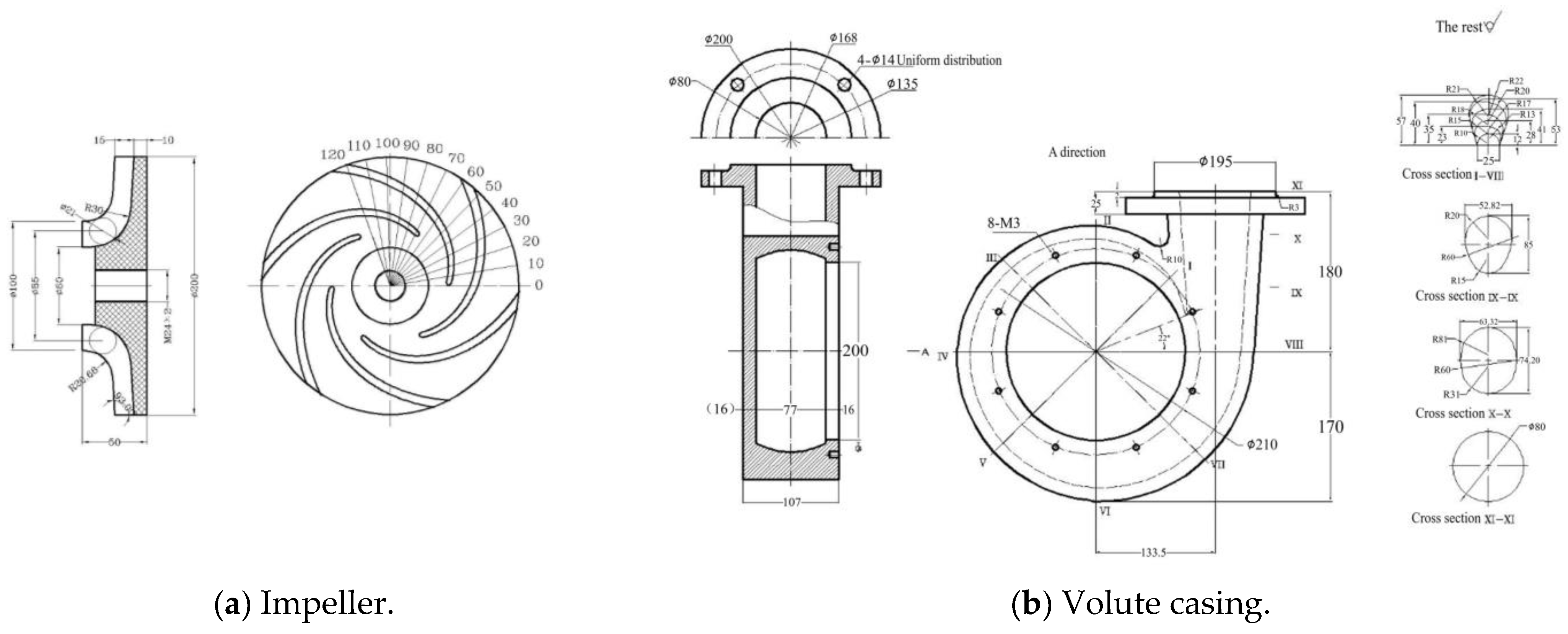
The centrifugal pump model studied is shown in
Figure 1.
The two-dimensional engineering drawing of the pump is shown in
Figure 2.
3. Study of Vibration Reduction in the Pump Shaft
3.1. Forced Torsional Vibration Model of the Pump Shaft
The shaft system of a single-stage centrifugal pump usually employs a single-span cantilever structure, as depicted in
Figure 3. Due to the impeller’s location at the extremity of the shaft system, its weight and load can induce bending deformations in the pump shaft. This deformation can lead to an increase in the reaction force on the bearings, potentially harming their normal functioning. During operation, the centrifugal pump’s bearings are subjected to both radial and torsional vibrations caused by the system’s inertia and elasticity. The phenomenon of resonance may arise when the vibration frequency of the pump shaft aligns with its internal vibration frequency. If the torsional stress exceeds the pump shaft’s allowable stress, there is a risk of shaft fracture.
The pump shaft of the plastic centrifugal pump incorporates an undamped single-mass system. Its structure can be referenced in
Figure 4 [
20].
By applying a continuous excitation torque,
M1 sinωt, the system transforms into a forced torsional vibration system. Disregarding the impact of damping, the motion differential equation of the system is expressed by Formula (11).
where
ω1—Excitation frequency, (Hz);
I—The moment of inertia of the disk, (kg·m2);
φ—The angular displacement of the disk, (rad);
M1—The excitation torque, (N·m).
The comprehensive solution to this differential equation is
where
A—The maximum angular displacement of the disk during torsional vibration is the amplitude, (rad);
φ0—Initial phase, (rad).
The influence of the excitation torque
M1 on free vibration is akin to the impact of the initial excitation torque
M0, typically represented by the static amplitude
A0.
where
K—The equivalent torsional stiffness of the system.
The amplitude of forced vibration,
A1, is computed using Formula (13), influenced by the excitation torque
M1.
where
The phase angle
is a crucial parameter that illustrates the angle between the excitation torque
M1 and the displacement
φ. In a non-damped forced vibration scenario, this angle
typically takes values of 0 or π. Hence, the sign of the amplitude value can express it [
21].
3.2. Vibration Reduction Method and Design
The silicone oil damper mainly consists of four components: the end cover, shell, inertia body, and supporting bearing, illustrated in
Figure 5. The end cover and shell form a sealed cavity, within which the inertia body is free to rotate. Uniform gaps between these elements are maintained by the supporting bearing, and these gaps are filled with high-viscosity silicone oil.
Integrating the silicone oil damper, the pump shaft system model simplifies into a dual-mass equivalent structure, as shown in
Figure 6. The system’s movement equations are represented by Formula (14).
where
Ie—Equivalent moment of inertia of the pump shaft system (kg·mm2);
Ke—Equivalent torsional stiffness of the pump shaft system;
Cd—Damping coefficient of the silicone oil damper;
—Angular velocity of the equivalent concentrated mass (rad/s);
—Angular velocity of the damper’s inertia block (rad/s).
The solution to Equation (14) is given by
Substituting the solution of Formula (15) into Equation (14) yields
According to the determinant method,
where
Ad—Actual amplitude of the damper’s inertia ring disc;
Ae—Actual amplitude of the pump shaft’s equivalent disc.
where
Formula (19) shows that the vibration characteristics of the pump shaft change significantly with the use of the silicone oil damper. In this case, the damping coefficient Cd emerges as the critical factor in assessing the effectiveness of the damper.
According to Formula (19), the amplitude curve of the silicone oil damper is plotted in
Figure 7. The graph indicates that under extreme conditions of
Cd = 0 and
Cd = ∞, the pump shaft’s amplitude sharply increases, potentially leading to resonance. Thus, between
Cd = 0 and
Cd = ∞, there must exist an optimal damping point
P, where energy dissipation is maximized and the pump shaft system experiences minimal vibration.
- (1)
Calculation of Inertia Ratio and Rotational Inertia of the Inertia Ring
Based on the pump shaft’s permissible torsional vibration stress, the resonant torsional angle must be less than 2.618 × 10
−3 rad. The amplification factor
A of the silicone oil damper is calculated using Formula (20).
where
Amax—The maximum torsional angle (rad).
The inertia ratio
μ is determined using Formula (21).
where
μ—represents the inertia ratio.
From A = 4.84, through Formula (21), can be obtained.
The rotational inertia of the inertia ring is calculated with Formula (22).
- (2)
Determination of the Optimal Damping Coefficient
From
Figure 7, point P is where the curves for
Cd = 0 and
Cd = ∞ intersect, independent of damping
Cd. If a damping value
Cdp exists that minimizes the system amplitude
Aep,
Cdp is considered optimal damping. The frequency at point P is calculated with Formula (23).
The amplitude
Aep corresponding to point P is calculated using Formula (24).
The optimal damping
Cdp is
- (3)
Structural Dimensions of the Inertia Ring
The rotational inertia of the inertia ring is determined by its structural dimensions, as shown in
Figure 8. The dimensions are calculated using Formula (26) [
22]; the specific dimensions are shown in
Figure 8.
where
Ri—represents the inner radius of the inertia ring (mm);
R0—denotes the outer radius of the inertia ring (mm);
B—indicates the width of the inertia ring (mm).
The structure size of the inertia ring of the silicone oil shock absorber is shown in
Figure 9. The primary sources of vibration in the pump shaft transmission system originate from the coupling connecting the electric motor and the pump shaft. For optimal vibration damping, the design places the damper near the vibration source. In this design, the silicone oil damper is bolted to the flanged coupling, as depicted in
Figure 10. Using Creo 5.0 software, a 3D model of the inertia ring was established, confirming that the calculated rotational inertia
Ie of the inertia ring meets the design requirements, as shown in
Figure 11.
It is concluded that the inertia ring meets the design specifications.
- (4)
Gap between Damper Shell and Inertia Ring
The gap between the damper shell and inertia ring is calculated using Formula (27).
where
δ—represents the gap between the damper shell and inertia ring (mm).
Assembly diagrams of the silicone oil damper and its coupling with the coupling are shown in
Figure 12 and
Figure 13.
A comparison of the pump shaft transmission system’s parameters before and after vibration reduction through the silicone oil damper is summarized in
Table 2. The table indicates a significant decrease in both torsional vibration frequency and amplitude after the addition of the damper, highlighting the system’s overall effective vibration reduction.
4. Experimental Study on the Relationship between Pump Shaft Speed and Deflection
This experiment aims to analyze the impact of rotational speed changes on the deflection of a centrifugal pump’s shaft rotor system below its first critical speed.
The test was conducted using a ZT-3-type rotor vibration test platform. The rotor at the cantilever end served as the experimental measurement point, with a span-to-cantilever ratio of 1:0.75. The test rig is depicted in
Figure 14, and the actual setup is shown in
Figure 15.
The experimental platform utilizes the DH5910A data acquisition system, which offers flexibility in selecting the type of channels, supporting up to 128 measurement channels. The system operates in a frequency range from 10 Hz to 128 Hz, accommodating most types of measurement requirements. The eddy current sensor model used in the platform is HZ-891YT08HP-M10×1-B-01-05-50. The testing software employed is DHDAS2013, a signal testing and analysis software featuring comprehensive analysis capabilities, including time-domain waveforms, bode plots, and shaft center trajectory representations.
The test rig is powered by a direct current (DC) motor, connected to the shaft via a rigid coupler, which drives the disc rotor to rotate. The rotational speed of the system is captured by a photoelectric speed sensor, while the vibrational displacement is measured by an eddy current sensor. The signals, after being filtered and shaped by the data collector, are transmitted to a monitoring computer through a 1394 interface card. The setup of the testing system is illustrated in
Figure 16.
Table 3 presents the experimental data correlating pump shaft rotational speed with deflection, as obtained from the test platform.
The experimental data were fitted using MATLAB R2016a software, employing polynomial fitting methods ranging from the first to sixth order. The fitting results are shown in
Figure 17.
The mathematical expressions for the first- to sixth-order polynomials are shown in
Table 4.
R-square is used to describe the degree of fit of a model to data, ranging in value from [0, 1]. Smaller values indicate poorer fit, and larger values indicate better fit, as shown in Equation (28).
where
—represents the mean value;
—The sample value;
—The fitted value.
The Root Mean Square Error (RMSE) is calculated using Equation (29).
Table 5 summarizes the Sum of Squares due to Error (SSE), R-squared, and RMSE parameters for each polynomial fit compared to the experimental values. According to these data, the sixth-order polynomial shows the best evaluation.


