Article

Single-Shot Full Characterization of the Spatial Wavefunction of Light Fields via Stokes Tomography

1
Wang Da-Heng Center, Heilongjiang Key Laboratory of Quantum Control, Harbin University of Science and Technology, Harbin 150080, China
2
Centro de Investigaciones en Óptica, A.C., Loma del Bosque 115, Colonia Lomas del Campestre, León 37150, Guanajuato, Mexico
3
CAS Key Laboratory of Quantum Information, University of Science and Technology of China, Hefei 230026, China
*
Author to whom correspondence should be addressed.
Appl. Sci. 2024, 14(5), 2067; https://doi.org/10.3390/app14052067
Submission received: 22 November 2023 / Revised: 22 February 2024 / Accepted: 26 February 2024 / Published: 1 March 2024
(This article belongs to the Special Issue Advances in Laser Beam Shaping Technology)

Abstract

:
Since the diffraction behavior of a light field is fully determined by its spatial wavefunction, i.e., its spatial complex amplitude (SCA), full characterization of spatial wavefunction plays a vital role in modern optics from both the fundamental and applied aspects. In this work, we present a novel “complex-amplitude profiler” based on spatial Stokes tomography with the capability to fully determine the SCA of a light field in a single shot with high precision and resolution. The SCA slice observed at any propagation plane provides complete information about the light field, thus allowing us to further retrieve the complete beam structure in the 3D space as well as the exact modal constitution in terms of spatial degrees of freedom. The principle demonstrated here provides an important advancement for the full characterization of light beams with a broad spectrum of potential applications in various areas of optics, especially for the growing field of structured light.

1. Introduction

The term “wavefunction” usually refers to a complex-valued function in modern quantum theory that is used to completely describe a field entity and predict its dynamical behavior [1,2]. For a light field propagating in free space or in a preknown optical system, once its spatial wavefunction is determined at a certain propagation plane, the whole diffractive propagation can be known exactly. This function is commonly known as the spatial complex amplitude (SCA) [3]. Therefore, SCA characterization plays a vital role in modern optics for both fundamental studies and applications. The experimental determination of an SCA requires two complementary measurements to record its modulus and argument (or phase) distributions. The modulus distribution describes the amplitude structure of the light field and is an observable (or rather, its absolute square) that can be directly recorded via a variety of modern photoelectric detectors, such as a charge-coupled device (CCD). The argument distribution, which carries the wavefront structure information, cannot be observed with photodetectors. Thus, its determination can be accomplished only via indirect measurements, i.e., using wavefront sensing, which maps the phase information in an imaginary variable to an intensity signal that can be measured with photodetectors.
Current wavefront sensing techniques fall into two categories: microlens-array focal plane imaging and interferometric measurement approaches [4,5,6,7,8,9,10,11]. Both approaches have intrinsic limitations: the former decreases the system’s spatial resolution and phase sensitivity, and the latter requires multistep interference and phase shifting operations, making the system complicated and sensitive to vibrations. These limitations cause many applications to abandon the complicated but important characterization of SCA. The absence of wavefront information has obvious adverse impacts on the performance and simplicity of light field characterization. Taking the best-known beam quality characterization as an example [12,13], to characterize the beam quality without wavefront information (because the commonly used beam profiler can only record the intensity profile), it is necessary to record a series of intensity profiles of the beam in different propagation planes. However, even so, due to the lack of full SCA information, it is still impossible to predict the exact diffraction behavior of a beam in free space or an optical system. In this work, we present a complex-amplitude profiler capable of determining the exact SCA of a light field with a single-shot measurement. This novel technique exploits spatially resolved polarimetry (or Stokes tomography) with ancillary light, which is realized by using low-cost, integratable polarization sorting elements and a commercial camera. Below, we experimentally show that, with the SCA determined in a single propagation plane, one can achieve the full characterization of the measured beam, including the whole diffraction behavior and corresponding modal constitution.

2. Principle and Methods

To prove the principle with specific examples, we chose paraxial structured Gaussian beams as unknown signals to be characterized. The transverse SCA of a beam upon propagation (referred to as the complete 3D spatial wavefunction) can be fully described (or predicted) by a solution of the paraxial wave equation, an analog of the Schrödinger equation for free particles with time t replaced by the propagation coordinate z , expressed as follows:
ψ s i g . r , z = u r , z exp i v r , z ,
where u r , z and v r , z are the spatial amplitude and wavefront, respectively, and r denotes the transverse coordinates. In particular, Equation (1) belongs to an eigensolution of the paraxial wave equation (commonly referred to as a paraxial eigenmode) when the beam profile on z is self-similar; otherwise, it can be represented as a superposition of eigensolutions with different modal orders [14]. Notably, the full 3D spatial wavefunction can be retrieved from a transverse SCA in an arbitrary propagation plane using the diffraction (or path) integral [3,15]. Namely, to fully characterize a light beam, it is required to record both u r and v r exactly at the same measuring plane z m .
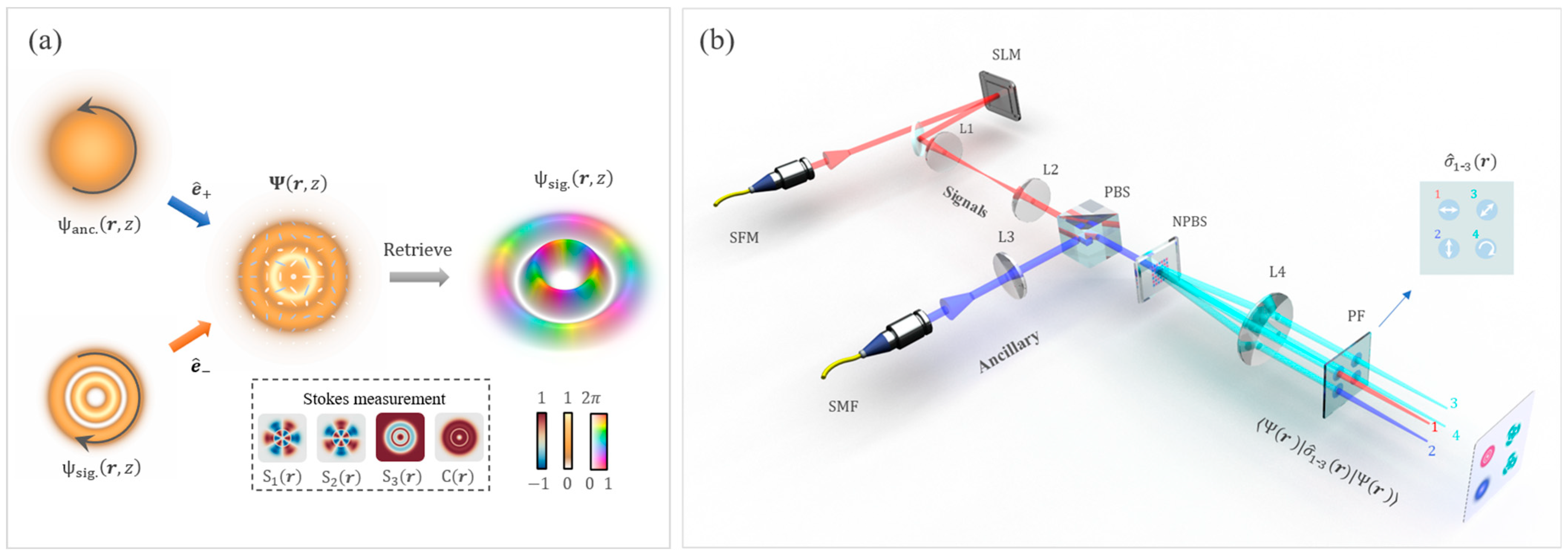
For this task, as shown in Figure 1a, we introduce an ancillary beam, denoted as ψ a n c . r , z , and combine it with the signal beam, both carrying orthogonal circular state of polarization (SoP) e ^ ± , to generate a vector spatial mode given by [16,17,18].
Ψ r , z = a ψ a n c . r , z e ^ + + e i θ 1 a ψ s i g . r , z e ^ .
Here, a 0 ,   1 is a weighting coefficient that controls the degree of spin-orbit nonseparability (also known as concurrence) between ψ s i g . and ψ a n c . overlapping positions, which is the maximum for the position r 0 as a g r 0 = 1 a u r 0 ; θ is the intramodal phase between the two polarization components. For convenience, we take a well-known ancillary mode, the fundamental Gaussian mode, whose minimum beam width, acquired for z = 0 , coincides with the measuring plane. That is, ψ a n c . r , z m = g r exp i k z , where g r denotes a 2D Gaussian amplitude envelope whose cross section can cover the signal mode well. In this way, the vector mode at the measuring plane can be further represented as follows:
Ψ r , z m = a g r e ^ + + e i v r , z m 1 a u r , z m e ^ .
Here, we assumed the global e ^ ± intramodal phase θ = 0 for simplicity, which can be realized in experiments via SoP control. In mode (3), the ancillary light works as a reference beam that copropagates with the signal along the same beam axis. Therefore, the vector mode can be regarded as a phase-stable polarizing interferometer.
We now perform a spatially resolved Stokes measurement on the vector mode given by Equation (3), namely, Ψ r , z m σ ^ 1 3 ( r ) Ψ r , z m , where σ ^ 1 3 are Pauli matrices for SoP tomography [19,20]. The measured expectation values are a group of mutually unbiased observables named spatial Stokes distributions S 1 3 ( r ) (see Appendix C for details), from which it is possible to reconstruct the spatially variant SoP of the vector mode. This measurement provides an in situ visualization for vector modes generated and manipulated in experiments, so it has been widely used in the structured light community [21,22,23,24]. Remarkably, the complete information about the signal SCA is already hidden in the morphological feature of the observed spatially variant SoP, which manifests in the spatial polarization orientation functions, defined as follows:
ϕ r = 1 2 a t a n 2 S 2 r , S 1 r ,
where a t a n 2 y , x [ 0 , 2 π ) is the 2-argument arctangent. Since the function 2 ϕ r describes the relative phase between the two polarization components for each position in the beam cross section, and since the ancillary wavefront is completely known, we can retrieve the wavefront of the signal from the relation 2 ϕ r = v r , z m . On this basis, combined with the signal amplitude u r , z m that has been obtained in the SoP tomography (projection result on e ^ ), the complete information about the signal beam at the measuring plane, i.e., ψ s i g . r , z m , is determined.
Regarding the accuracy (or uncertainty) of the wavefront determination, in this technique, the wavefront information of the beam is first converted to the intramodal phase of the vector mode in Equation (3), reflected in the spatial polarization orientation in Equation (4), and then determined via spatial Stokes tomography. That is, the accuracy of the wavefront estimation relies on that of the polarization orientation estimation for each position (or pixel) in the beam cross section. From this perspective, the accuracy reaches its maximum as the local polarization reaches a linear SoP, i.e., as a g r 0 = 1 a u r 0 for the position r 0 , which corresponds to a minimum value (zero) in S 3 , and gradually decreases as it approaches a circular SoP. Therefore, we can use the spatial concurrence of the observed spatially varying SoP, given by C r = 1 S 3 2 ( r ) 0 ,   1 , to indicate the accuracy of the wavefront estimation [20,25], as shown schematically in Figure 1a. For a region with a near-circular SoP, i.e., a g r 0 1 a u r 0 1 , one can adjust the power of ancillary light (i.e., a ) to make the local concurrence C r 0 approach 1 and remeasure the SoP distribution there.
Figure 1. (a) Schematic of the principle. (b) Experimental setup, where the key components are the single-mode fiber (SFM), polarizing beam splitter (PBS), nonpolarizing beam splitter (NPBS), polarizing filter (PF), spatial light modulation (SLM), and lens (L1–L4).
Applsci 14 02067 g001

3. Experimental Results

Figure 1b shows the schematic setup for the proof-of-principle demonstration. A tunable continuous laser operating at a wavelength of 780 nm was used as the light source. We began with a TEM00 mode collimating from a single-mode fiber for easy control in further SCA shaping. In signal preparation, we used a spatial light modulator (SLM), in which we loaded a specially designed hologram for performing complex-amplitude modulation and digital propagation [25], to shape the signal light (represented by a red beam in the schematic setup) into a desired spatial mode with a controllable diffraction distance. The prepared signal was first relayed by a 4f imaging system (L1 and L2) and combined afterwards with the ancillary beam via a polarizing beam splitter (PBS) to obtain the vector mode discussed above. The ancillary beam came from the same laser source and was also shaped into a TEM00 mode by collimating with a single-mode fiber. To avoid the challenge that comes from SoP intramodal-phase jitter, the spatially variant SoP of the vector mode was measured in a single-shot manner. Specifically, the vector mode was divided into four equal parts, which were then projected into horizontal, vertical, diagonal, and circular SoPs. After that, the four SoP projections, which can be converted to S 0 3 ( r ) , were recorded simultaneously within the same frame of the camera (not drawn in the figure). Here, a nonpolarizing beam splitter (NPBS) with four output ports was realized by a liquid-crystal geometric phase, and the polarizing filter (PF) comprised waveplates and a polarizer (see Appendix C). Moreover, lens L4 performed a Fourier transformation for the signal beam in combination with the SLM to realize digital propagation; the ancillary beam was expanded two times by lenses L3 and L4 to ensure that it could fully cover the signal beam.
In the experiments, we first took the well-known structured Gaussian modes—the Hermite–Laguerre–Gaussian (HLG) family—as signal beams to be characterized [26]. Figure 2a shows the observed SCA patterns of the prepared signal beams at the waist plane ( z = 0 ). The patterns in the top and bottom rows are the Laguerre–Gaussian (denoted as L G l , p ) and Hermite–Gaussian (denoted as H G m , n ) modes, respectively, and their intermediates are shown in the middle row. The three HLG modes in each column correspond to a continuous astigmatic transformation from the LG polar to the HG equator on the same spatial-mode sphere with the same order N , where N = 2 p + l = m + n and l = m n [27,28,29]. Note that, except for the special case of N > 1 , the intermediate HLG mode can no longer be represented as a linear superposition of the two orthogonal LG (or HG) modes on the sphere but as a superposition of all the possible LG (or HG) modes with an order of N (i.e., including modes not on this sphere) [14]. All the measurements agree well with the theoretical SCAs of the desired modes; see extended data in Appendix B. These SCAs provide complete knowledge about the spatial structure of measured beams, with which, in principle, we can exactly predict the diffraction behavior of each beam in free space or an optical system. That is, we can theoretically reconstruct the full spatial wavefunction of a beam, i.e., ψ s i g . r , z , by using the diffraction integral with the SCA observed at the measuring plane, i.e., ψ s i g . r , z m , as the source (or pupil function); see Appendix A for details.
Since the modes in Figure 2a all belong to eigensolutions of the paraxial wave equation, their beam profiles should be propagation-invariant apart from an overall change in size. To validate the observations in Figure 2a, we compare the changes in beam diameter upon diffraction obtained from the theoretical reconstruction and the slice-by-slice observation. This characterization method also relates to the generalized beam quality measurement for high-order Gaussian beams, i.e., the M 2 value, and the ideal value is M 2 = N + 1 [14]. Figure 2b provides a visual description of the method, with the L G 2,1 mode as an example, in which the two 3D beam profiles used for the comparison are obtained via slice-by-slice observation (using the digital propagation technique) and theoretical reconstruction (using the diffraction integral). The similarity between both makes it difficult to determine the difference between the two 3D beam profiles with the naked eye. Figure 2c further provides an intuitive comparison for all five LG modes, where all the observed beam sizes (dots) fit closely on their corresponding predictions (curves) calculated through numerical diffraction, confirming the observation accuracy in Figure 2a. Thus, not surprisingly, the beam quality factors ( M 2 values) calculated with the two approaches (dots and curves) as input are almost the same. Notably, beam characterization based on the M 2 measurement has many limitations for high-order modes, especially for superposition modes.
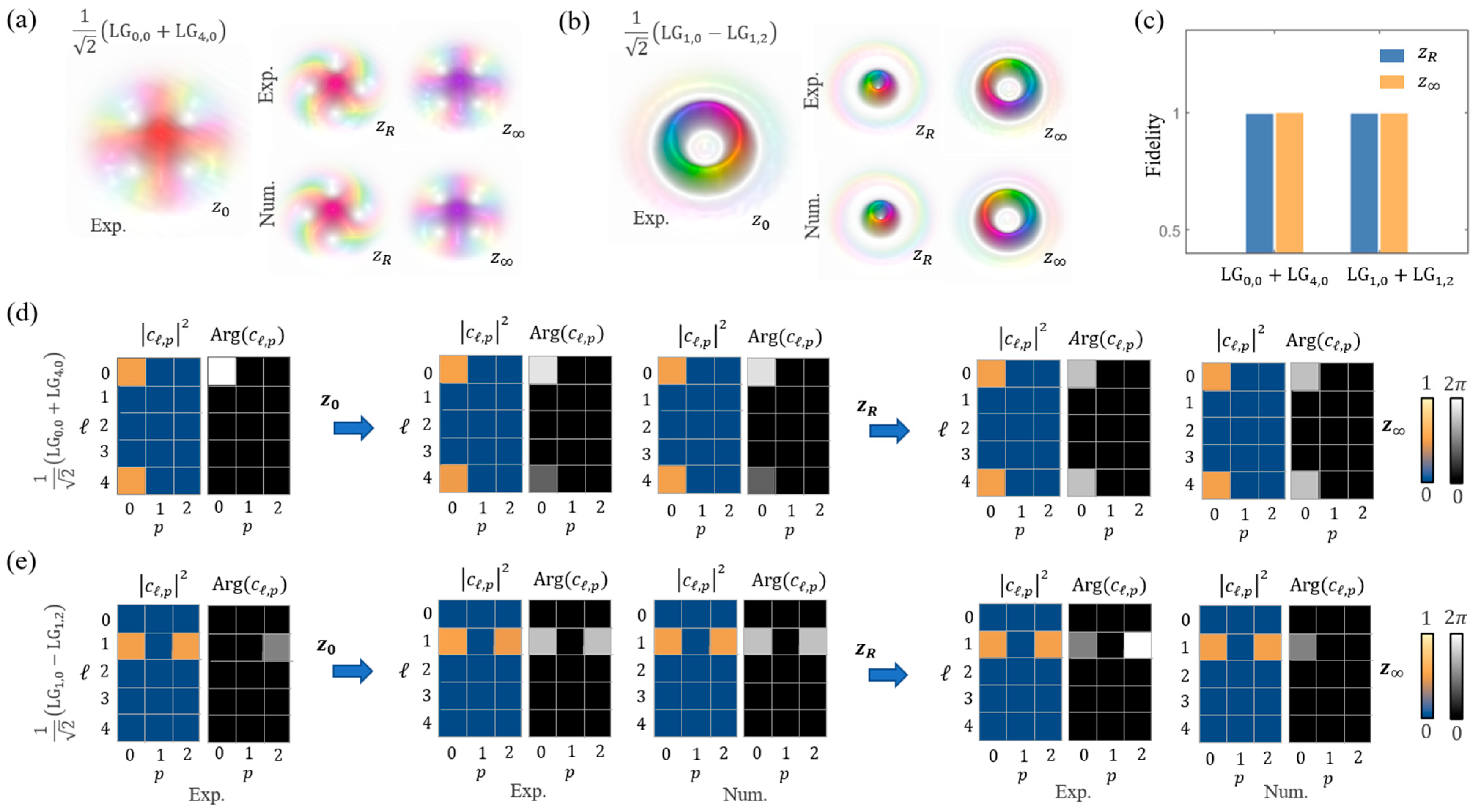
We further proved the principle by characterizing the beam structure evolution of two superpositions of LG modes, given by c 0,0 L G 0,0 + c 4,0 L G 4,0 and c 1,0 L G 1,0 + c 1,2 L G 1,2 , and, here, we set all complex coefficients c l , p = 1 / 2 for simplicity. Owing to their different Gouy phases N + 1 arctan z / z R , the beam structures would no longer be propagation-invariant. Relevant studies have indicated that the changes in beam structure manifest in azimuthal rotation and radial oscillation, and both exhibit pattern revival in the far field [30,31]. This inference was confirmed by the results in Figure 3a,b, which show the beam structure evolution of the two superposed LG modes. That is, ψ o b s . r , z is recorded at the z = 0 , z = z R , and z = z (Fourier) planes, and ψ n u m . r , z is calculated with z = z R and z = z by using the observation at z = 0 as input. The numerical reconstruction looks the same as the previously measured one. To make a quantitative examination, we calculated the fidelity of reconstruction, defined by F = ψ o b s . r , z ψ n u m . r , z , and the high fidelity shown in Figure 3c validates the accuracy of the characterization.
Finally, beyond morphological observations, we can further derive the modal constitution of light fields (i.e., quantum state or density matrix) in terms of spatial degrees of freedom. This task is usually accomplished by using quantum state tomography [19,20], which requires multiple projections on all mutually unbiased bases, leading to a complicated and time-consuming operation, especially for high-dimensional states. Moreover, recent works showed that astigmatic operation and machine-learning-based pattern recognition can also be used to determine simple OAM superimposition states [32,33]. In contrast, the SCA characterization provides complete information on light fields and, thus, enables the direct and easy determination of the complex-valued modal spectrum by computing projections on a complete orthogonal basis, such as the LG basis set; see Appendix B. This capability has great potential for applications in high-dimensional state characterization and optical topology [20,34,35,36,37,38]. Additionally, this enables us to conveniently analyze and predict the beam evolution of the light fields mentioned above from an algebraic viewpoint [30,31]. For instance, Figure 3d,e show the computed modal constitutions (i.e., the LG modal complex spectra c l , p ) of the two superposed modes, respectively. It was shown that the modal weights (or power spectrum) remained constant upon propagation, i.e., c l , p 2 = 1 / 2 , while the intramodal phase between two successive LG components, due to unsynchronized Gouy phase accumulation, varied from 0 to π when arriving z = z R and finally backed to 0 (or 2 π ) at the far field z = z . This analysis clearly shows the mechanism of beam evolution and revival upon diffraction from an algebra perspective, which, in fact, exists widely in compounded systems undergoing unitary transformations [30,39,40]. In addition, the modal constitutions of HLG modes in Figure 2a are provided in Appendix B, showing that each mode has an identical modal order and, thus, is propagation-invariant.

4. Conclusions

We have experimentally demonstrated a “complex-amplitude profiler” that can completely determine the SCA of a light field with a single-shot measurement. This novel technique exploits spatially resolved polarimetry with ancillary light to determine both the amplitude and wavefront of unknown beams. Specifically, the unknown signal light field to be measured was first combined with a preknown ancillary light via orthogonal polarization states, forming a vector mode equivalent to a phase-stable polarizing interferometer; then, by performing a spatial Stokes measurement on the vector mode, the SCA of the signal can be determined with high precision and spatial resolution. On this basis, one can further theoretically reconstruct the full 3D spatial wavefunction and derive the modal constitution in the spatial degrees of freedom exactly. In particular, the device is capable of performing a single-shot measurement, providing it with real-time characterization and insensitivity to vibrations. In addition, this technique only requires some low-cost and integratable polarization sorting elements that can be easily incorporated into the existing beam characterization system. Notice, however, that the ancillary light and the measured beam should come from the same laser source (for coherent states) or photon (for single-photon states). A feasible way to experiment is to use a single-mode fiber to sample the partial energy (or probability amplitude) of the signal light (or photons).
Since SCA characterization allows access to complete information about light fields, the principle demonstrated here has a broad spectrum of potential applications in various areas of optics. For instance, this principle can help researchers to unambiguously probe the topology hidden in a structured light field or the high-dimensional quantum state encoded with spatial degrees of freedom [34,35,36,37,38]. In addition to fundamental studies, this principle can also be coupled with developing optical techniques based on structured light, such as in situ detection on spatially multiplexed channels or structured sensing beams [35,41]. Beyond paraxial beams, this technique can also be used to completely characterize the complex spectrum of an imaging signal, enabling further implementation of arbitrary spatial analog computing on the signal [42].

Author Contributions

Conceptualization, Z.Z.; Software, H.W.; Validation, C.L., J.J. and B.Z.; Investigation, B.Y. and Z.Z.; Writing—original draft, Z.Z.; Writing—review and editing, C.R.-G. and B.S.; Funding acquisition, Z.Z. All authors have read and agreed to the published version of the manuscript.

Funding

This work was supported by the National Natural Science Foundation of China (Grant Nos. 11934013, 62075050, 61975047, and 62275070), the High-Level Talents Project of Heilongjiang Province (Grant No. 2020GSP12), and the Heilongjiang Provincial Education Department (Grant No. UNPYSCT-2020185).

Institutional Review Board Statement

Not applicable.

Informed Consent Statement

Not applicable.

Data Availability Statement

The raw data supporting the conclusions of this article will be made available by the authors on request.

Conflicts of Interest

The authors declare no conflict of interest.

Appendix A. Hermite–Laguerre–Gaussian Modes

The transverse structure of a paraxial light field and its corresponding evolution upon propagation can be fully described by a solution of the paraxial wave equation (PWE), which can be regarded as an analog of the Schrödinger equation for free particles. Except for an ideal plane wave, any eigensolution of the wave equation corresponds to a physically realizable “eigen” spatial mode, whose transverse structures are propagation-invariant apart from an overall change in size. For instance, the well-known Laguerre–Gauss (LG) and the Hermite–Gauss (HG) modes are eigensolutions of the PWE in cylindrical and Cartesian coordinates, respectively, and their complex amplitudes are as follows:
L G l , p r , φ , z = 2 p ! π p + l ! 1 w z 2 r w z l exp r 2 w z 2 L p l 2 r 2 w z 2 e i k z + k r 2 2 R z + l φ N + 1 ϕ ,
H G m , n x , y , z = 2 1 n m π n ! m ! 1 w z e x p r 2 w z 2 H m 2 x w z H m 2 y w z e i k z + k r 2 2 R z N + 1 ϕ ,
where z R = k w 0 2 / 2 ,   w z = w 0 1 + ( z / z R ) 2 , and R z = z 2 + z R 2 / z are the Rayleigh length, beam waist, and radius of curvature, respectively. L p l · and H m / n · denote the Laguerre and Hermite polynomials, respectively. The term ϕ = arctan ( z / z R ) is the propagation-dependent Gouy phase, and their modal orders are defined as N = 2 p + l = m + n . The above Hermite– and Laguerre–Gaussian mode families have their own special features in transverse structures but have the same fundamental TEM00 mode, and each can independently constitute a unique and unbounded 2D Hilbert space. Therefore, in principle, we can represent any Gaussian mode by using coherent superpositions (i.e., complex series) of LG, HG, or their intermediate Hermite–Laguerre–Gaussian (HLG) modes. i.e., the generalized Hermite–Laguerre–Gaussian (HLG) mode. All the possible N-order HLG modes following the relation l = m n can form the surface of a unit sphere, called a modal sphere, and unitary transformations for states on the sphere can be realized by using astigmatic operations.
Astigmatic transformation (AT) refers to a unitary operation based on astigmatic propagation that makes a beam have different Gouy phases with respect to a given orthogonal axis. Specifically, the Gouy phase of H G m , n can be represented as follows [26,27]:
N + 1 ϕ = m + 1 / 2 ϕ x + n + 1 / 2 ϕ y , ϕ x , y = arctan ( z x , y z R x , R y )
For instance, the modal conversion H G 1,0 45 ° L G 1,0 requires a relative phase retardation δ = ϕ y ϕ x = π / 2 . So, we have the following:
H G 1,0 45 ° = 1 / 2 H G 1,0 + H G 0,1 1 / 2 H G 1,0 + i H G 0,1 = L G 1,0 ,
In order to check the accuracy of spatial-mode generation and observation, Figure A1 shows the theoretical reference of the observed HLG modes in Figure 2a.
Figure A1. Extended data. Simulated spatial complex amplitudes at z = 0 of HLG modes, as shown in Figure 2a.
Applsci 14 02067 g0a1
In addition, the observed SCA profile at the measuring plane, denoted as ψ r , z m , provides complete information about the light field. Thus, we can further retrieve the complete beam structure in the 3D space, denoted as ψ r , z , by using the Collins (or Kirchhoff) diffraction integral with ψ r , z m as the source, which in cylindrical coordinates can be expressed as follows:
ψ r , φ , z = i λ z exp ( i k z ) r 0 d r 0 d φ 0 ψ ( r 0 , φ 0 , z m ) exp i k 2 z × [ r 0 2 2 r r 0 cos ( φ φ 0 ) + r 2 ] .

Appendix B. Spatial-Mode Projection Measurements Enabled by Spatial Complex Amplitude Observation

Projection measurement in terms of spatial degrees of freedom has the same mathematical formalism as the Fourier transformation. For instance, the projection measurement to obtain complex-valued coefficients of a superposed LG mode ψ r = c l , p L G l , p can be expressed as follows:
c l , p = c l , p exp i A r g ( c l , p ) = L G l , p ψ r .
Notably, the experimental implementation of such projective measurement, i.e., quantum state tomography, has been well established in optics. To date, however, there is no strict projective instrument for measuring spatial modes, and instead, the widely used toolkit is a spatial autocorrelation measurement. The far-field pattern of the spatial autocorrelation function C r = ψ r L G l , p r can indeed provide the real-value output c l , p 2 , which is, thus, equivalent to a standard experimentally projective measurement. However, owing to losing the imaginary part of c l , p , one has to implement more projections on a mutually unbiased basis for each of the two successive LG components. For the present technique, in contrast, we have recorded the complete spatial complex amplitude (SCA) of the measured beam, ψ o b s . r , z P . Thus, we can directly access the complex-valued coefficients c l , p by performing Equation (A6) with an observed ψ r as input on a computer. Here, we also provide the calculated LG spectrum of observed HLG modes in Figure 2a, as shown below:
Figure A2. Extended data. Calculated modal spectrum of observed HLG modes in Figure 2a.
Applsci 14 02067 g0a2

Appendix C. Spatial Stokes Tomography for Vector Modes

The outputs of the spatial Stokes tomography mentioned in the main text, i.e., Ψ r σ ^ 0 - 3 ( r ) Ψ r , are a set of mutually unbiased real-valued functions, or rather, spatial distributions of Stokes parameters, given by the following:
S 0 ( r ) = 1 a ψ R 2 + a ψ L 2 S 1 ( r ) = ψ H 2 ψ V 2 S 2 ( r ) = ψ D 2 ψ A 2 S 3 ( r ) = 1 a ψ R 2 a ψ L 2
where ψ H , V , D , A , L , R denote spatial probabilities or polarization-dependent spatial modes observed in the projections along the horizontal, vertical, diagonal, antidiagonal, left-, and right-circular polarizations, respectively. Notice that ψ H ( D ) and ψ V ( A ) are not usually orthogonal to each other, only in the case when a = 0.5 . With the observations in Equation (A7), we can in situ reconstruct the polarization-resolved beam profile of the vector mode, expressed as follows:
p r = S 0 r ρ ^ r .
Here, S 0 r describes the intensity profile of the beam, while ρ ^ r = 1 2 0 3 S n ( r ) σ ^ n is a density matrix function that describes a spatially varying polarization distribution covered by the beam profile, as shown in Figure 1a. According to Equations (A7) and (A8), the tomography can be further simplified by using only H, V, D, and L polarization projections. On this basis, in order to implement the simplified tomography within a single-shot measurement, we adopt a nonpolarizing beam splitter (NPBS) with four output ports and an integrated polarizing filter (PF), as shown below:
Figure A3. Details of the nonpolarizing beam splitter based on liquid-crystal geometric phase. The integrated polarizing filter and similar commercial products are available at https://www.lbtek.com/product/837.html (accessed on 1 January 2024).
Applsci 14 02067 g0a3

References

  1. Wheeler, J.-A.; Zurek, W.-H. Quantum Theory and Measurement; Princeton University Press: Princeton, NJ, USA, 1983; pp. 9–49. [Google Scholar]
  2. D’Ariano, G.M.; Matteo, G.A. Paris, and Massimiliano F. Sacchi, Quantum Tomography. arXiv 2003, arXiv:quant-ph/0302028. [Google Scholar]
  3. Max, B. Principles of Optics-Electromagnetic Theory of Propagation, Interference and Diffraction of Light, 7th ed.; Pergamon Press: Oxford, UK, 1999. [Google Scholar]
  4. Platt, B.-C.; Shack, R.-V. History and principles of Shack-Hartmann wavefront sensing. J. Refract. Surg. 2001, 17, S573. [Google Scholar] [CrossRef]
  5. Roddier, F. Curvature sensing and compensation: A new concept in adaptive optics. Appl. Opt. 1988, 27, 1223–1225. [Google Scholar] [CrossRef]
  6. Velghe, S.; Primot, J.; Guérineau, N.; Cohen, M.; Wattellier, B. Wave-front reconstruction from multidirectional phase derivatives generated by multilateral shearing interferometers. Opt. Lett. 2005, 30, 245–247. [Google Scholar] [CrossRef]
  7. Andersen, G.-P.; Dussan, L. Holographic wavefront sensor. Opt. Eng. 2009, 48, 085801. [Google Scholar]
  8. Dudley, A.; Milione, G.; Alfano, R.-R.; Forbes, A. All-digital wavefront sensing for structured light beams. Opt. Express 2014, 22, 14031–14040. [Google Scholar] [CrossRef]
  9. Norris, B.; Wei, J.; Betters, C.-H.; Wong, A.; Leon-Saval, S.-G. An all-photonic focal-plane wavefront sensor. Nat. Commun. 2020, 11, 5335. [Google Scholar] [CrossRef]
  10. Park, T.; Depeursinge, C.; Popescu, G. Quantitative phase imaging in biomedicine. Nat. Photonics 2018, 12, 578–589. [Google Scholar] [CrossRef]
  11. Takeda, M.; Ina, H.; Kobayashi, S. Fourier-transform method of fringe-pattern analysis for computer-based topography and interferometry. J. Opt. Soc. Am. 1982, 72, 156–160. [Google Scholar] [CrossRef]
  12. ISO 11146-1; Lasers and Laser Related Equipment-Test Methods for Laser Beam Widths, Divergence Angles and Beam Propagation Ratios. Part 1: Stigmatic and Simple Astigmatic Beams. International Organization for Standardization: Geneva, Switzerland, 2005.
  13. ISO 11146-2; Lasers and Laser Related Equipment-Test Methods for Laser Beam Widths, Divergence Angles and Beam Propagation Ratios. Part 2: General Astigmatic Beams. International Organization for Standardization: Geneva, Switzerland, 2005.
  14. Dennis, M.-R.; Alonso, M.-A. Swings and roundabouts: Optical Poincaré spheres for polarization and Gaussian beams. Philos. Trans. R. Soc. A Math. Phys. Eng. Sci. 2017, 375, 20150441. [Google Scholar] [CrossRef] [PubMed]
  15. Collins, S.-A. Lens-System Diffraction Integral Written in Terms of Matrix Optics. J. Opt. Soc. Am. 1970, 60, 1168–1177. [Google Scholar] [CrossRef]
  16. Zhan, Q.-W. Cylindrical vector beams: From mathematical concepts to applications. Adv. Opt. Photonics 2009, 1, 1–57. [Google Scholar] [CrossRef]
  17. Pereira, L.-J.; Khoury, A.-Z.; Dechoum, K. Quantum and classical separability of spin-orbit laser modes. Phys. Rev. A 2014, 90, 053842. [Google Scholar] [CrossRef]
  18. Rosales-Guzmán, C.; Ndagano, B.; Forbes, A. A review of complex vector light fields and their applications. J. Opt. 2018, 20, 31. [Google Scholar] [CrossRef]
  19. Toninelli, E.; Ndagano, B.; Vallés, A.; Sephton, B.; Forbes, A. Concepts in quantum state tomography and classical implementation with intense light: A tutorial. Adv. Opt. Photonics 2019, 11, 67–134. [Google Scholar] [CrossRef]
  20. D’Ariano, G.M.; Paris, M.G.; Sacchi, M.F. Quantum Tomography. Adv. Imaging Electron Phys. 2003, 128, 205–308. [Google Scholar]
  21. Forbes, A.; Oliveira, M.D.; Dennis, M.-R. Structured light. Nat. Photonics 2021, 15, 253. [Google Scholar] [CrossRef]
  22. Wang, J.; Castellucci, F.; Franke-Arnold, S. Vectorial light-matter interaction: Exploring spatially structured complex light fields. AVS Quantum Sci. 2020, 2, 031702. [Google Scholar] [CrossRef]
  23. Zhao, B.; Hu, X.-B.; Rodríguez-Fajardo, V.; Zhu, Z.-H.; Rosales-Guzmán, C. Real-time Stokes polarimetry using a digital micromirror device. Opt. Express 2019, 27, 31087. [Google Scholar] [CrossRef]
  24. Li, C.-Y.; Liu, S.-J.; Yu, B.-S.; Wu, H.-J.; Rosales-Guzmán, C.; Shen, Y.; Chen, P.; Zhu, Z.-H.; Lu, Y.-Q. Toward Arbitrary Spin-Orbit Flat Optics Via Structured Geometric Phase Gratings. In Laser Photonics Reviews; Wiley: Hoboken, NJ, USA, 2023; p. 2200800. [Google Scholar]
  25. Rosales-Guzmán, C.; Forbes, A. How to Shape Light with Spatial Light Modulators; SPIE Press: Bellingham, WA, USA, 2017. [Google Scholar]
  26. Abramochkin, E.-G.; Volostnikov, V.-G. Generalized Gaussian beams. J. Opt. A Pure Appl. Opt. 2014, 6, S157. [Google Scholar] [CrossRef]
  27. Gutiérrez-Cuevas, R.; Dennis, M.-R.; Alonso, M.-A. Generalized Gaussian beams in terms of Jones vectors. J. Opt. 2019, 21, 084001. [Google Scholar] [CrossRef]
  28. Beijersbergen, M.-W.; Allen, L.; Veen, H.E.L.O.V.D.; Woerdman, J.-P. Astigmatic laser mode converters and transfer of orbital angular momentum. Opt. Commun. 1993, 96, 123–132. [Google Scholar] [CrossRef]
  29. Wu, H.-J.; Yu, B.-S.; Jiang, J.-Q.; Li, C.-Y.; Rosales-Guzmán, C.; Liu, S.-L.; Zhu, Z.-H.; Shi, B.-S. Observation of anomalous orbital angular momentum transfer in parametric nonlinearity. Phys. Rev. Lett. 2023, 130, 153803. [Google Scholar] [CrossRef] [PubMed]
  30. Zhong, R.-Y.; Zhu, Z.-H.; Wu, H.-J.; Rosales-Guzman, C.; Song, S.-W.; Shi, B.-S. Gouy-phase-mediated propagation variations and revivals of transverse structure in vectorially structured light. Phys. Rev. A 2021, 103, 053520. [Google Scholar] [CrossRef]
  31. da Silva, B.P.; Pinillos, V.-A.; Tasca, D.-S.; Oxman, L.-E.; Khoury, A.-Z. Pattern revivals from fractional Gouy phases in structured light. Phys. Rev. Lett. 2020, 124, 033902. [Google Scholar] [CrossRef] [PubMed]
  32. da Silva, B.P.; Tasca, D.S.; Galvão, E.F.; Khoury, A.Z. Astigmatic tomography of orbital-angular-momentum superpositions. Phys. Rev. A 2019, 99, 043820. [Google Scholar] [CrossRef]
  33. da Silva, B.P.; Marques, B.A.D.; Rodrigues, R.B.; Ribeiro, P.H.S.; Khoury, A.Z. Machine-learning recognition of light orbital-angular-momentum superpositions. Phys. Rev. A 2021, 103, 063704. [Google Scholar] [CrossRef]
  34. Erhard, M.; Fickler, R.; Krenn, M.; Zeilinger, A. Twisted photons: New quantum perspectives in high dimensions. Light Sci. Appl. 2018, 7, 17146. [Google Scholar] [CrossRef] [PubMed]
  35. Ndagano, B.; Nape, I.; Cox, M.A.; Rosales-Guzman, C.; Forbes, A. Creation and Detection of Vector Vortex Modes for Classical and Quantum Communication. Light. Technol. 2018, 36, 292–301. [Google Scholar] [CrossRef]
  36. Sugic, D.; Droop, R.; Otte, E.; Ehrmanntraut, D.; Nori, F.; Ruostekoski, J.; Denz, C.; Dennis, M.-R. Particle-like topologies in light. Nat. Commun. 2021, 12, 6785. [Google Scholar] [CrossRef]
  37. Salakhutdinov, V.; Eliel, E.; Löffler, W. Full-field quantum correlations of spatially entangled photons. Phys. Rev. Lett. 2012, 108, 173604. [Google Scholar] [CrossRef] [PubMed]
  38. Brandt, F.; Hiekkamäki, M.; Bouchard, F.; Huber, M.; Fickler, R. High-dimensional quantum gates using full-field spatial modes of photons. Optica 2020, 7, 98–107. [Google Scholar] [CrossRef]
  39. Yu, B.-S.; Li, C.-Y.; Yang, Y.-J.; Rosales-Guzmán, C.; Zhu, Z.-H. Directly determining orbital angular momentum of ultrashort Laguerre-Gauss pulses via autocorrelation measurement. Laser Photonics Rev. 2022, 16, 2200260. [Google Scholar] [CrossRef]
  40. Courtial, J.; Dholakia, K.; Allen, L.; Padgett, M.-J. Second-harmonic generation and the conservation of orbital angular momentum with high-order Laguerre-Gaussian modes. Phys. Rev. A 1997, 56, 4193–4196. [Google Scholar] [CrossRef]
  41. Zhang, X.-Y.; Wu, H.-J.; Yu, B.-S.; Rosales-Guzmán, C.; Zhu, Z.-H.; Hu, X.-P.; Shi, B.-S.; Zhu, S.-N. Real-time superresolution interferometric measurement enabled by structured nonlinear optics. In Laser & Photonics Reviews; Wiley: Hoboken, NJ, USA, 2023; p. 202200967. [Google Scholar]
  42. Abdollahramezani, S.; Hemmatyar, O.; Adibi, A. Meta-optics for spatial optical analog computing. Nanophotonics 2020, 9, 4075–4095. [Google Scholar] [CrossRef]
Figure 2. Experimental results for paraxial eigenmodes. (a) Observed HLG modes with orders N from 1 to 5, where the colored arrow displays the path of the astigmatic transformation from LG to HG modes on the modal sphere; (b) visual comparison for numerically reconstructed (diffraction integral) and experimentally observed (via digital propagation) 3D profiles of the measured L G 2,1 mode; and (c) comparison of observed and predicted changes in beam size of measured LG modes as well as associated M 2 values.
Applsci 14 02067 g002
Figure 3. Experimental results for noneigen paraxial modes. (a,b) Observed superposed LG modes at z = 0 , z = z R , and z = z (Fourier) planes, and corresponding numerical reconstructions based on observations at z = 0 plane; (c) SCA reconstruction fidelity relative to the observation; and (d,e) modal constitutions and of two superposed LG modes and associated unitary evolution upon propagation.
Applsci 14 02067 g003
Disclaimer/Publisher’s Note: The statements, opinions and data contained in all publications are solely those of the individual author(s) and contributor(s) and not of MDPI and/or the editor(s). MDPI and/or the editor(s) disclaim responsibility for any injury to people or property resulting from any ideas, methods, instructions or products referred to in the content.