Abstract
The shear strength of unsaturated soils exhibits significant nonlinearity, while previous studies often simplified it with linear strength models. The objective of this paper is to investigate the distinctions in the stability of three-dimensional (3D) tunnel faces when using linear and nonlinear strength models. A new 3D rotational failure mechanism and an extended form of the Mohr–Coulomb (M-C) failure criterion were integrated into the kinematically limited analysis (KLA) framework to describe the failure characteristics of tunnel faces. Subsequently, the factor of safety (FS) of the 3D tunnel faces was calculated using the strength reduction method (SRM). In the discussion section, the impacts of nonlinear shear strength, matric suction in the unsaturated soils, and the 3D geometric parameters of the tunnel on the stability of the tunnel face were analyzed. The outcomes indicate that, in unsaturated soil conditions, diverse nonlinear strength calculation models and soil types exert disparate influences on the FS of 3D tunnel faces. The main novelty of this study lies in establishing an effective method for assessing the stability of tunnel faces in unsaturated soils.
1. Introduction
A substantial body of the literature includes two-dimensional (2D) analyses concerning the stability of tunnel faces, typically presuming either saturated or completely dry soil conditions [1,2]. Nonetheless, it is essential to recognize that the stability analysis of tunnel faces is intrinsically a three-dimensional (3D) problem. Neglecting spatial effects in the analysis framework of a 2D failure mechanism is evidently impractical in real tunnel engineering scenarios [3]. Furthermore, the soil is often in an unsaturated state due to the influence of matric suction. The strength properties in unsaturated soils differ significantly from those in saturated soils [4,5,6]. Hence, a series of innovative works have been introduced within the academic community to tackle the characteristics of unsaturated soils [7]. To develop a more accurate scheme, it is essential to integrate the influence of unsaturated components into the 3D failure mechanism.
The analysis methods for assessing the stability of geotechnical problems include limit equilibrium (LE) [8,9,10,11], experimental modeling (ME) [12], computational simulation (CS) [13,14], and kinematically limited analysis (KLA) [15,16,17,18]. Among these methods, LE is commonly employed for investigating the stability of tunnel faces by solving static equilibrium equations. For instance, Oreste et al. [19] developed a new triangular prism model based on LE to determine the factor of safety (FS) for tunnel faces reinforced by positioning lines. Anagnostou and Perazzelli [20] utilized a wedge model to assess the stability of tunnel faces under the influence of Clear Span and nonuniform support. Lu et al. [21] focused on calculating the lowest supporting force necessary for tunnel faces experiencing seepage conditions, addressing stability concerns. In contrast to the LE, the KLA has the ability to optimize the failure mechanism and has been widely used in various geotechnical engineering scenarios [22,23,24]. During the course of optimizing the kinematic mechanism, Leca and Domieux [25] were the pioneers involved in proposing a 3D kinematic mechanism involving double blocks, which paved the way for more advanced analyses in tunnel stability assessments. On this basis, Mollon et al. [26] proposed a modified multi-block mechanism to obtain more accurate solutions. The horned failure mechanism has been utilized in the examination of tunnel face safety, and its results are in good agreement with both numerical simulations and experimental observations [27].
In the context of the New Austrian Tunnel Method (NAT), the tunnel face is not subjected to supporting pressure [28,29]. Consequently, evaluating the stability of the tunnel face using the FS is a more appropriate approach than considering supporting pressures. There are two approaches for delineating the FS: the strength reduction method (SRM) and the gravity augmentation method (GAM). In the GAM, the FS is expounded as the quotient of the internal energy dissipation rate to the external energy dissipation rate. Nonetheless, within the SRM paradigm, the FS is articulated as the quotient of the real soil strength to the critical strength in the state of limit equilibrium. This approach yields a more cautious resolution when contrasted with the GAM, consequently rendering SRM a prevalent choice for assessing the stability of Mohr–Coulomb (M-C) materials.
Numerous scholars have delved into the influence of matric suction on shear strength within the domain of geotechnical engineering, particularly concerning the unsaturated constituents of soil strength [30,31,32,33]. To account for unsaturated properties in soils, Fredlund et al. [34] modified the M-C criterion and proposed the concept of matric suction angle. Following this, various estimation formulas were advanced to assess the strengths of unsaturated soils across diverse soil classifications [35,36,37,38,39]. Extensive research has been conducted in the academic realm concerning the analysis of unsaturated soil strength, with a focus on topics such as slope stability and retaining walls. However, there is a noticeable lack of studies addressing the safety of tunnel faces. As an instance, Zhang et al. [40] determined the critical groundwater level depth for retaining walls under varying distributions of matric suction in unsaturated soil, utilizing the temporal equilibrium method. Additionally, Oh and Lu [41] explored the consequences of rainfall-induced failures on engineering slopes under unsaturated conditions. These investigations highlight the significance of matric suction on influencing soil strength and motivate the author to incorporate unsaturated components into tunnel face safety analyses in order to attain more precise solutions.
The primary objective of this study was to investigate the disparities in the stability of three-dimensional (3D) tunnel faces when employing linear and nonlinear strength models. To achieve this, a novel 3D rotational failure mechanism was developed to depict the failure of tunnel faces. In order to account for unsaturation in shear strength, an extended Mohr–Coulomb (M-C) criterion was adopted in this paper. Additionally, the strength reduction method (SRM) was utilized to compute the factor of safety (FS) of tunnel faces. Finally, the study examined the impact of the nonlinear shear strength of the soil, tunnel geometry characteristics, and matric suction in unsaturated soil on the safety of tunnel faces. The key novelty of this study lies in establishing an effective approach to assess the stability of tunnel faces in unsaturated soils.
2. Strength Theory of Unsaturated Soil
Linear and nonlinear forms of the unsaturated soil strength formula can be distinguished [42]. And both forms of equations are employed in this paper to calculate the impact of matric suction on tunnel face safety in unsaturated conditions.
2.1. Linear Shear Strength
In the linear cases, two forms of matric suction distribution are considered: uniform distribution and linear increase with burial depth. Fredlund et al. [34] introduced a formula for calculating soil strength under uniform matric suction based on the M-C failure criterion:
where denotes the shear strength of unsaturated soil, while and represent to the soil’s friction angle and cohesion, respectively. represents the net normal pressure, and represents the matric suction, with representing the pore water pressure and representing the pore gas pressure. is commonly referred to as the matric suction angle, which reflects the influence of matric suction on shear strength. According to previous studies [43], is often assumed to have a constant value of 15°.
Equation (1) can also be reformulated in the M-C criterion form as follows:
where the cohesive force, accounting for unsaturated strength components, is redefined as follows:
Furthermore, apart from the uniformly distributed matric suction, Zhang et al. [40] introduced an alternative linear distribution form, depicted in Figure 1. In this model, matric suction linearly increases with the buried depth, commencing from 0 at the groundwater level. This relationship can be described as follows:
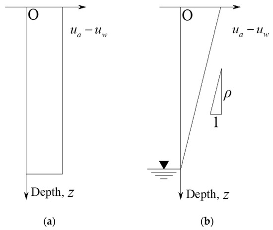
Figure 1.
The spatial variations in matric suction within unsaturated soils: (a) uniform distribution; (b) linear increase with burial depth.
In which represents the constant coefficient for matric suction linearly increasing with depth.
2.2. Nonlinear Shear Strength
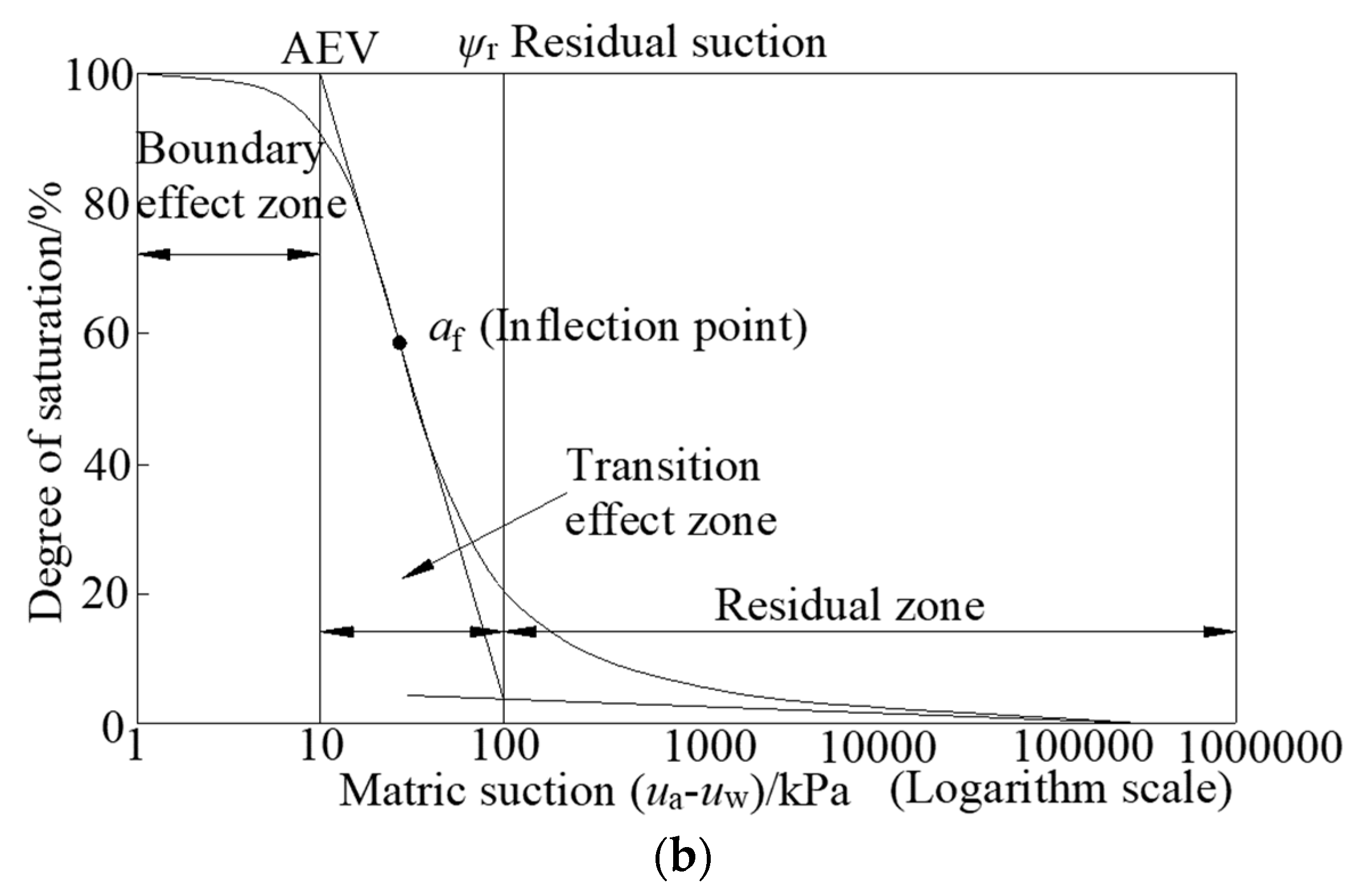
The shear strength of soil in unsaturated states is conventionally depicted in a linear fashion; nevertheless, a substantial corpus of empirical evidence attests to the pronounced nonlinearity exhibited by shear strength of soil in unsaturated conditions, particularly when subjected to the effects of matric suction [44,45]. This article posits several nonlinear equations to delineate the inter-relation between the shear strength of unsaturated soil and matric suction. Zhang et al. [46] encapsulated a selection of emblematic nonlinear equations, as shown in Table 1. In this context, signifies saturation, while signifies residual saturation. , , and correspond to volume moisture content, saturated volume moisture content, and residual volume moisture content, respectively. Furthermore, designates the ultimate undrained soil shear strength in a desiccated state, and designates residual matric suction. And AEV refers to the Air Entry Value.

Table 1.
Several formulas related to apparent cohesion, as compiled by Zhang et al. (2016) [40].
Table 2 enumerates the parameters characterizing the Soil–Water Characteristic Curve (SWCC) for four distinct soil classifications in accordance with the study by Fredlund and Xing [47]. Specifically, NO.1 corresponds to sandy soil, NO.2 corresponds to silt, NO.3 corresponds to clay, and NO.4 corresponds to ultra-fine-grained soil. In Table 2, , , and stand for the suction value, slope, and fitting parameter, respectively, which correspond to the inflection point in Figure 2b. It can be observed that various soil types exhibit substantial disparities in their shear strength profiles.
Table 2.
SWCC parameters by Fredlund and Xing (1994) [47].
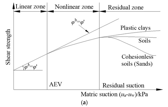

Figure 2.
The correlation between matric suction and SWCC: (a) shear strength envelopes for various soil types; (b) SWCC for a representative soil.
Furthermore, for the aforementioned representative soil specimens, Figure 2a illustrates the nonlinear correlation existing between matric suction and shear strength. Meanwhile, Figure 2b delineates the SWCC of a prototypical soil sample. It is clear from the AEV that shear strength demonstrates a notably linear association with saturated soil conditions. Upon surpassing the critical AEV, the shear strength envelope of the soil shows a nonuniform expansion pattern within the nonlinear domain. As the matric suction approaches the residual zone, sand demonstrates a diminishing tendency with the augmentation of matric suction, whereas plastic soil and silt exhibit a proclivity toward horizontal dispersion.
3. KLA in the 3D Horned Failure Mechanism
Figure 3 serves as a schematic representation of the practical tunnel engineering issue in a water-rich region. A cylindrical tunnel with a diameter denoted as D was excavated above the groundwater level devoid of any supporting pressure. H represents the burial depth of the tunnel, indicating the vertical measurement from the groundwater level to the tunnel’s base. In this paper, we can think of the soil’s unit weight as a fixed amount. And it is hypothesized that homogenous, unsaturated soil clings to an enlarged definition of the M-C yield function, as shown in Equation (3).
Figure 3.
Three-dimensional horned failure mechanism: (a) horizontal cross-section; (b) longitudinal cross-section.
3.1. Three-Dimensional Horned Rotational Failure Mechanism
In the investigation of tunnel face safety through the KLA approach, it is imperative to ascertain a rational presumed failure mechanism. This mechanism should adhere to the following assumptions in the KLA: (1) the soil mass complies with pertinent regulations; (2) the soil exhibits ideal plastic behavior. Additionally, there is one need that has to be met, namely the work exerted by outside forces can be no greater than the rate of energy dissipation., as follows:
where and indeed represent the strain and stress tensors, respectively. The failure body’s volume and border are precisely denoted by the and . And appropriately refers to the forces acting on the boundary face, while correctly refers to the body forces acting within the volume . accurately signifies the velocity along the failure face.
Numerous failure mechanisms have been posited within academic sphere as means to emulate tunnel collapse. When using discrete techniques, the horned mechanism differs from these others in that it is more conservative than the multi-block mechanism and easier to design than the rotating mechanism. Michalowski initially introduced the horned failure mechanism, which subsequently evolved into a potent tool for evaluating both slope stability and tunnel face safety. Therefore, considering its efficacy in practical application, this paper opts for the adoption of the horned failure mechanism.
This mechanism encompasses a pair of logarithmic spirals, denoted as AE and BE, sharing the central pivot at O and characterized by the angular velocity of ω. Schematic representations for the horizontal and longitudinal cross-sectional aspects are shown in Figure 3. In the realm of polar coordinates, the expressions for AE and BE are articulated as follows:
In which and denote the polar coordinates of points A and B, respectively. The polar radii, and , can be determined using the following equations:
The distance between the rotational center O and the horned mechanism’s center axis is as follows:
Each rotational segment’s radius is as follows:
The coordinates of the intersection point of the two logarithmic spirals are as follows:
When the tunnel burial depth appears to be shallow, the horned mechanism might emerge above the ground face. With such instances, the ground face CD, the tunnel face AB, and the two logarithmic curves AC and BD serve to define the bounds for this mechanism. The parameters and might be used separately for determining the coordinates of points C and D, where this mechanism intersects the surface of the ground, in the following manner:
As depicted in Figure 3, when the horn faces, the failure mechanism primarily involves three constituents, whereas if the horn remains submerged, it solely comprises two elements. Two autonomous variables, and , determine the configuration of the horned failure mechanism, and this configuration is then refined and resolved based on these two parameters.
3.2. Balance Equation for Work and Energy
In accordance with the KLA method, the balance equation for work and energy arises by equating the rate of energy dissipation to the rate of external work. And the self-weight of soil is a primary contributor to the rate of outside work. Meanwhile, the internal energy dissipation consists of two constituents: effective internal cohesion and matric suction-induced apparent internal cohesion . The formulation of the balance equation for work and energy is defined as follows:
where and correspondingly represent the rates of energy dissipation attributed to effective internal cohesion and matric suction-induced apparent internal cohesion . signifies the external work generated by one’s own weight. And the rate of outside work equals the summation of the gravitational work rate for each component, as illustrated below:
It is imperative to establish the basic premise that these collapsing blocks exhibit rigidity in order to determine the rate of internal energy dissipation. This premise enables the integration for the rate of internal energy dissipation as follows:
Here, signifies the cohesive strength of the soil, and signifies the failure face. Using Equation (17), it is possible to deduce the energy dissipation resulting from the effective cohesion of the soil .
where and can be ascertained through geometric relationships:
Similarly, the energy dissipation brought about by apparent cohesion is as follows:
In which the apparent cohesion induced via matric suction can be formulated as follows:
where represents the vertical distance from the groundwater level to a point on the tunnel failure face, and it can be expressed as follows:
3.3. Implicit Solution for the FS
The computation of the safety factor serves as an efficacious method for assessing the stability of tunnels excavated without applied support pressure. In this paper, the SRM is employed to determine the FS, a method that has found extensive application in M-C materials [48,49]. Within the framework of the SRM, the parameters, namely cohesion and the angle of internal friction, are progressively reduced until failure occurs. The FS is defined as the ratio of the current strength of the soil to the soil strength at a reduced state that leads to ultimate failure. Consequently, the FS can be written the following way:
As the soil strength, characterized by cohesion and the friction angle , is progressively diminished, the tunnel face approaches the ultimate failure state. Please be aware that the computation of the apparent cohesion induced via matric suction is interconnected with the internal friction angle and should not be further reduced subsequent to the reduction in the internal friction angle.
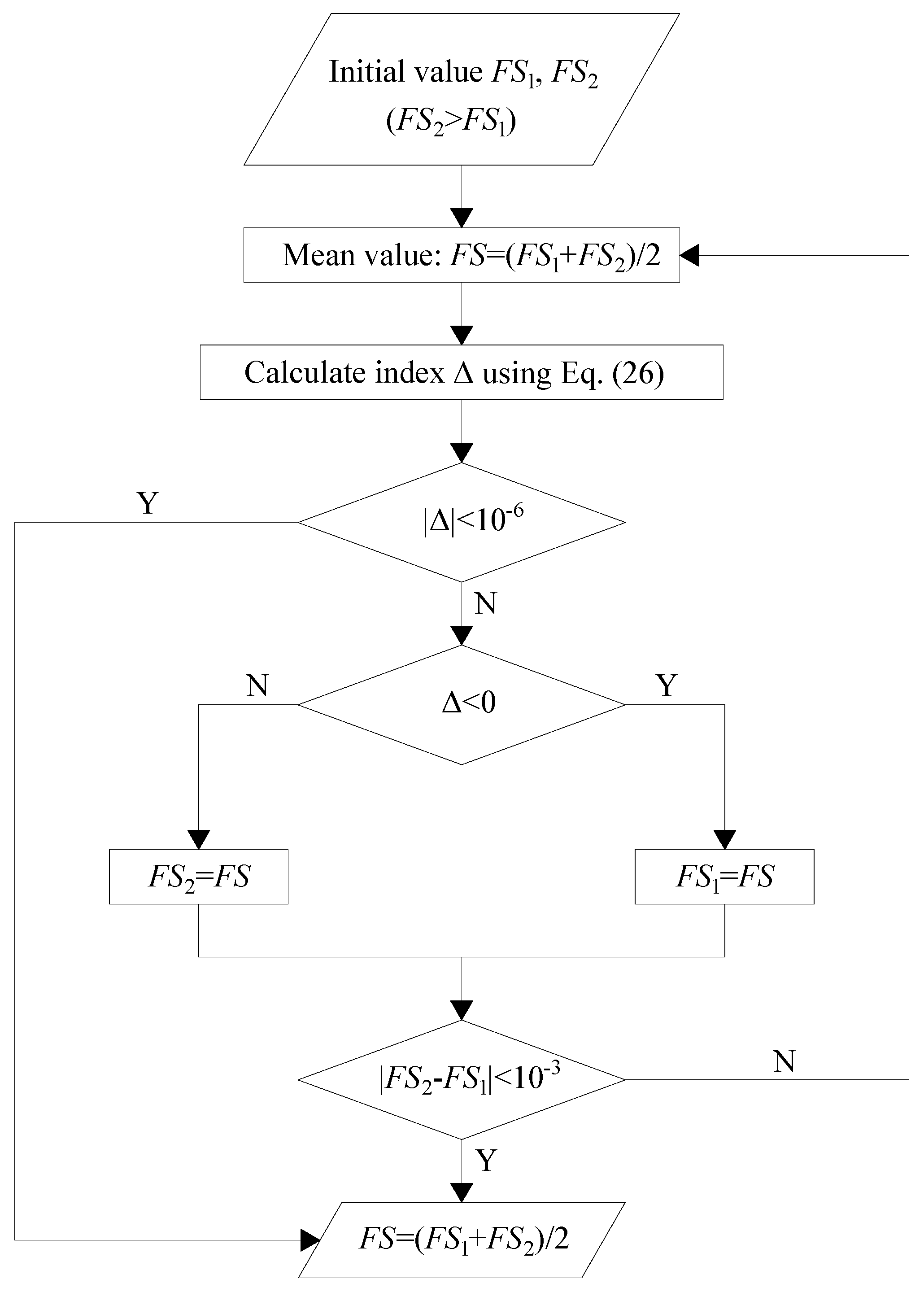
The SRM is utilized to formulate an implicit equation [50]. In this paper, the FS is derived through a binary search approach. The flowchart depicted in Figure 4 elucidates the principles of this method. A parameter without dimensions has been included to facilitate computation, as outlined below:
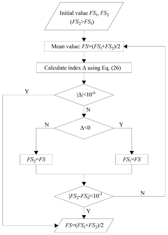
Figure 4.
Illustration portraying the SRM for assessing the FS.
For a specific FS, the variables and are utilized in an optimization procedure to arrive at the highest value for Equation (26). Initially, and , two initial amounts for the FS, are given, where corresponds to the upper limit of the FS for a stable state, while corresponds to the lower limit of the FS for an unstable situation. And the FS will be computed as the arithmetic average for and . When , signifying the stability of the tunnel face, the mean FS is employed instead of the lower limit . Conversely, when , indicating the instability of the tunnel face, the upper limit is substituted with the FS. This iterative process continues until either the absolute magnitude of falls below 10−6 or the disparity between and narrows to a level below 10−3. MATLAB (R2019b) Software is employed to implement the entire optimization procedure. The design idea of the procedure is formulated on the basis of the enumeration method, which means that all possible results are calculated one by one and the maximum result is extracted from them. And the enumeration precision and range of the corresponding variables are as follows: precision 0.5°, range of 2°~86° for ; precision 0.5°, range of 4°~88° for . Although this method seems to be more computationally intensive, it ensures the accuracy and repeatability of the data.
4. Results and Discussion
4.1. Comparisons
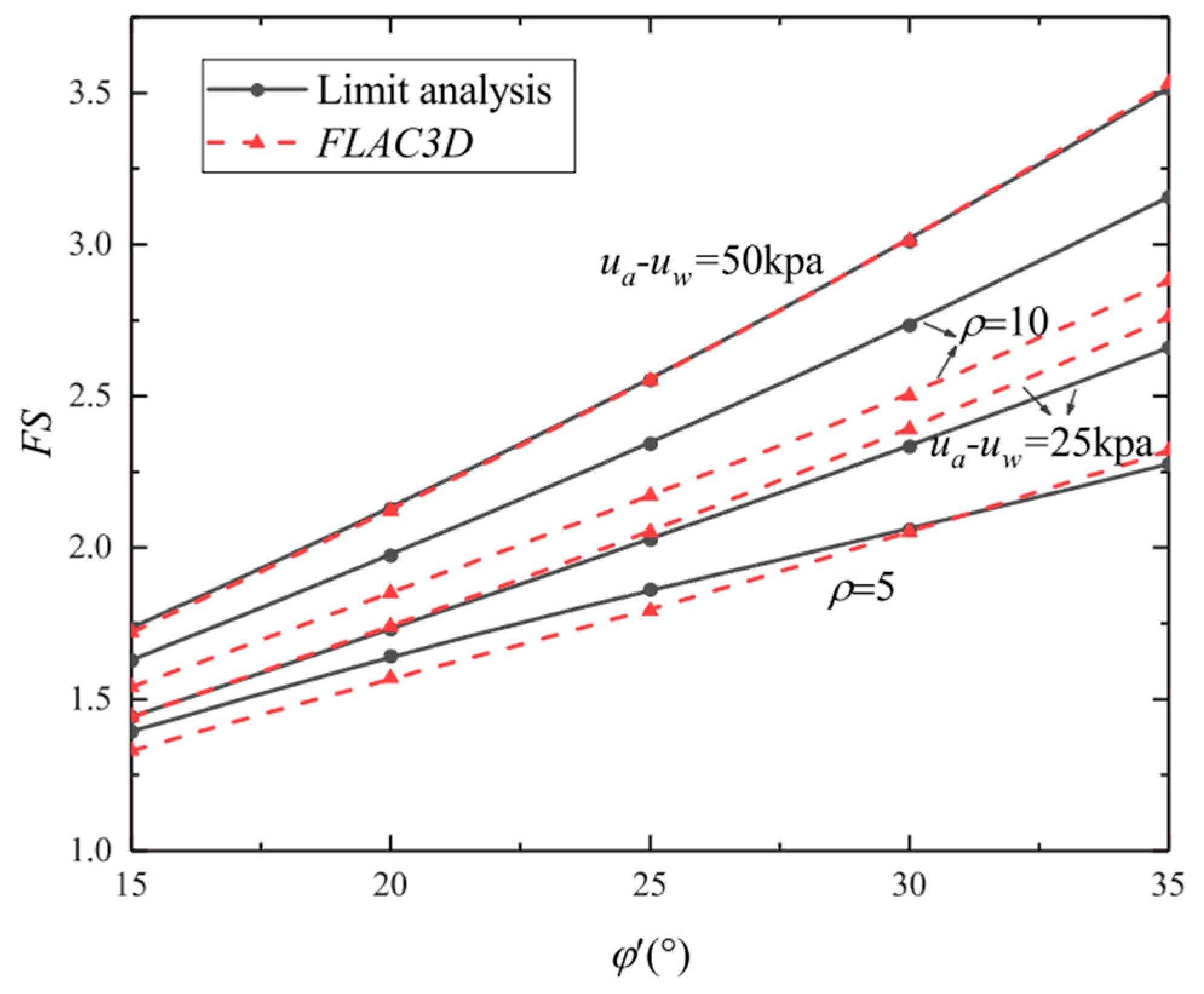
A numerical model based on FLAC 3D is developed to validate the correctness and effectiveness of the method proposed in this study. Due to the symmetry of the tunnel section, only half of the model is considered, as shown in Figure 5. The model boundary conditions are set at the bottom and both sides of the tunnel. The formula for apparent cohesion is selected from the results of Fredlund et al. (1996), as presented in Table 1. The unsaturated soil properties are chosen from SWCC NO. 3 in Table 2, and deformation characteristics are set as follows: Poisson’s ratio and elastic modulus . The remaining parameters are consistent with those of the KLA method employed in this study.
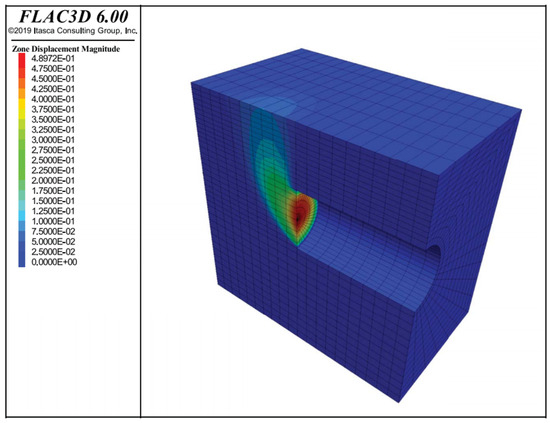
Figure 5.
Displacement contour map of the 3D tunnel face numerical model in FLAC 3D.
Two types of suction distribution are considered: uniform distribution and linearly increasing distribution. The comparison results are displayed in Figure 6. It can be observed that when suction is uniformly distributed (), the results from this method closely match those of the numerical simulation. In the case of linearly increasing suction (), the solutions from this method are slightly larger than the numerical simulation results, but the maximum difference does not exceed 9%. This discrepancy is attributed to the need for grid cell division in numerical simulation, leading to discontinuities in soil property parameters. Furthermore, the displacement contour in Figure 5 demonstrates that the 3D horned failure mechanism employed in this study aligns well with the simulated shape, providing additional evidence of the method’s correctness.

Figure 6.
Comparison between the results of the kinematically limited analysis (KLA) and FLAC 3D numerical simulation method.
4.2. Parameters Analysis
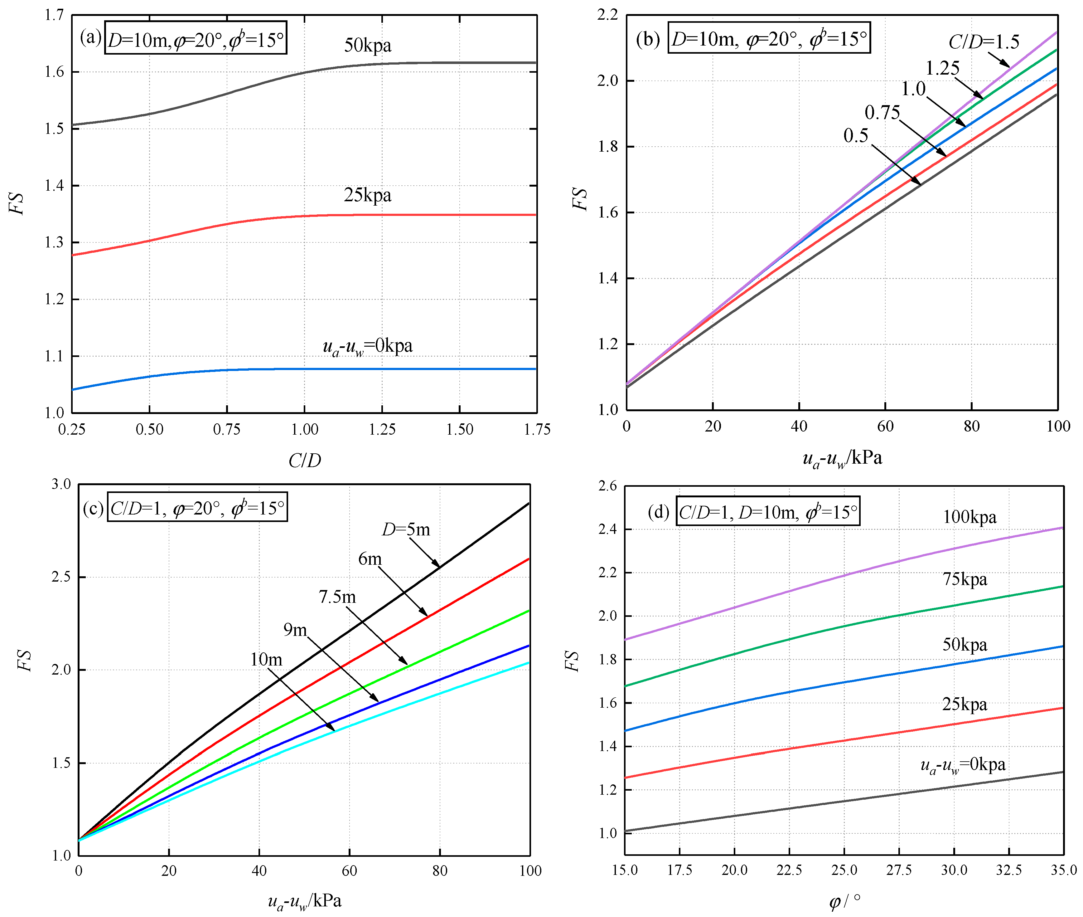
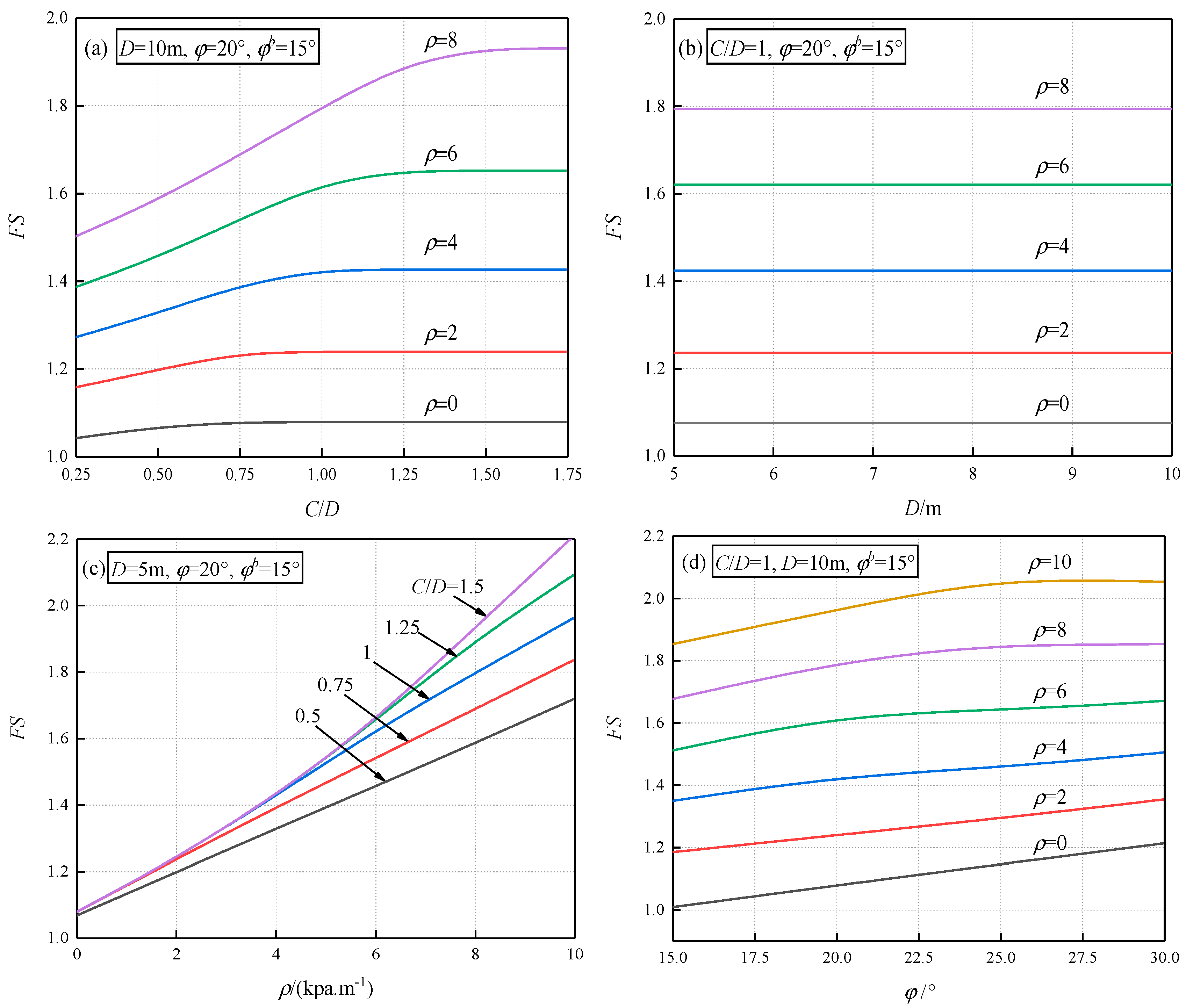
Through parameter analysis, this study investigates the impact of the nonlinear shear strength, geometric attributes of the tunnel, and matric suction on the safety of the tunnel cross-sections. Here are some of the parameter configurations: , , and .
4.2.1. Case 1—Uniformly Distributed Suction
Figure 7 depicts the FS of the tunnel face, considering uniform matric suction, where represents a constant. Figure 7a delineates the correlation between the FS and the burial depth ratio C/D for scenarios with D = 10 m, 0, 25, and 50 kPa. Figure 7b and Figure 7c, respectively, present the FS for different values of C/D and D. Figure 7d demonstrates the influence of the internal friction angle of the soil on the FS at varying matric suction levels.
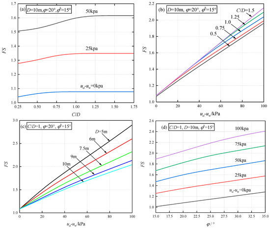
Figure 7.
The factor of safety (FS) for tunnel faces under uniformly distributed matric suction.
As depicted in Figure 7, it is evident that matric suction has a favorable impact on tunnel face safety. Figure 7a,b indicate that as C/D increases, the FS initially improves before reaching a plateau. Once the burial depth ratio C/D surpasses a specific threshold, the horned failure mechanism will become completely submerged underground, and the stability of the tunnel face will no longer be influenced by variations in C/D. In contrast to the scenario where suction is not taken into account, the maximum difference, following the consideration of uniform suction of 50 kPa, can reach up to 33.4%. Figure 7c,d indicate that, under the condition of C/D = 1, as the suction and pressure increase, the FS exhibits nearly linear growth. Additionally, smaller values of D prove advantageous for the stability of the tunnel face, and changes in D have a relatively limited effect on the influence of the FS.
4.2.2. Case 2—Linearly Increasing Suction
This section presents the safety factor of the tunnel face under the condition of linearly increasing matric suction. Figure 8a,b illustrate the trends in how the FS is affected by C/D and D across various linear increase coefficients. Figure 8c,d delineate the impacts of variations in and on the FS.

Figure 8.
The factor of safety (FS) for tunnel faces under linearly increasing matric suction conditions.
It is evident that an increase in can significantly enhance the stability of the tunnel cross-sections. As illustrated in Figure 8a, the FS increases as C/D rises up until C/D surpasses a certain threshold. Under conditions of smaller , the critical C/D value at which the FS transitions to a stable state is relatively low. From Figure 8b, it is evident that variations in D do not affect the FS. Referring to Figure 8c, it can be observed that when C/D is small, the FS linearly increases with , whereas when C/D is large, the pattern of the FS variation with respect to begins to exhibit nonlinearity. This suggests that when C/D is large, the impact of p on the FS becomes more pronounced. In Figure 8d, an increase in can bolster the FS until and attain specific larger values.
4.2.3. Case 3—Nonlinear Shear Strength
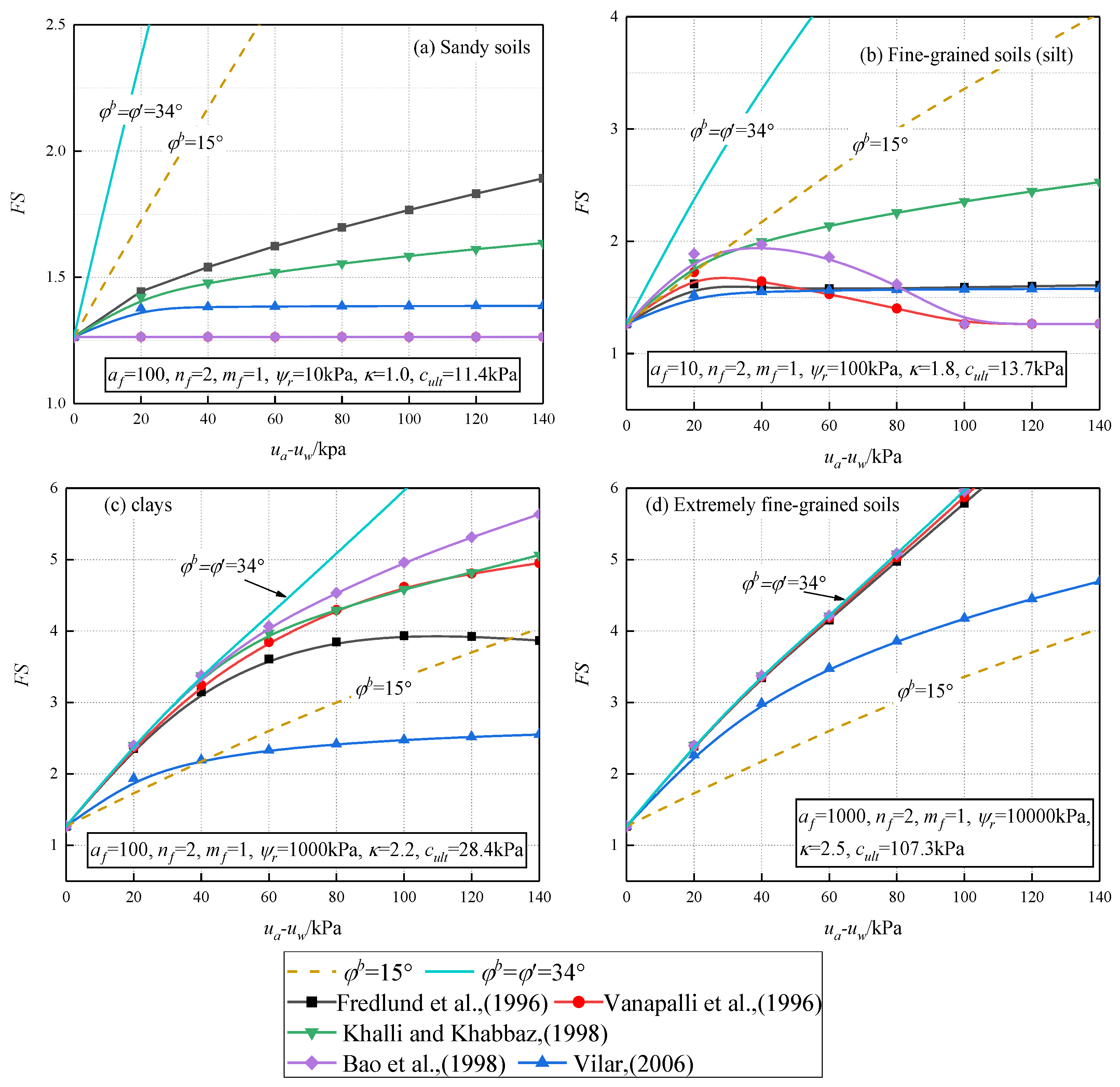
The impact of soil strength nonlinearity on tunnel cross-section stability, based on the nonlinear strength equations from Table 1 and various soil characteristics from Table 2, is depicted in Figure 9, in which Figure 9a–d represent the nonlinear shear strengths of sandy soil, silt, clay, and ultra-fine grained soil, respectively. In this section, specific parameters were preselected: , D = 5 m, and C/D = 1.
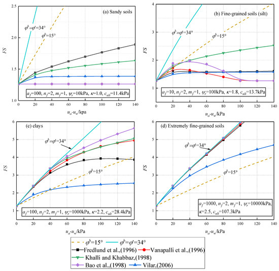
Figure 9.
The factor of safety (FS) for tunnel faces under nonlinear shear strength conditions: (a) sandy soils; (b) fine-grained soils (silt); (c) clays; (d) extremely fine-grained soils [35,36,37,38,39].
As depicted in Figure 9, varying assessing equations for nonlinear strength and soil kinds result in various impacts for matric suction in soil on the FS of tunnel face, as shown in Figure 9. In the case of sandy soil, the curves for Vanapalli et al. (1996) [35] and Bao et al. (1998) [38] exhibit a flat and overlapping trend, indicating that these two models can be considered for saturated conditions. Regarding the other three models, the pattern of the FS varies nonlinearly within the range of 40 kPa, and subsequently, it linearly increases with the augmentation of matric suction. In comparison to the case where the suction angle is constant (), under the nonlinear equations, suction has a relatively minor effect on the stability of sandy soil tunnel faces.
For fine-grained soils, the curves of the Bao et al. (1998) [38] and Vanapalli et al. (1996) [35] models exhibit a similar pattern, both increasing nonlinearly at low suction, before gradually decreasing and ultimately degenerating into a horizontal and overlapping configuration. The curves for Fredlund (1996) [36] and Vilar (2006) [39] indeed exhibit a close resemblance, both eventually converging to stability. Additionally, the curve for Khalili and Khabbaz (1998) [37] is notably higher than the other nonlinear curves. When compared to sandy soil, the nonlinearity of fine-grained soil has a more pronounced effect on the stability of the tunnel face.
In the case of clay, when matric suction remains within 40 kPa, the trends of variation for all nonlinear curves, except for the Vilar model, are largely consistent with . Subsequently, the growth trends of the curves become more gradual. Only the curve for Vilar et al. (2006) [39] falls below and ultimately levels off. For ultra-fine grained soil, apart from the Vilar model, the safety factor curves are essentially consistent with the safety factor curve at , and the nonlinearity can be considered negligible. This aligns with the findings of Zhang et al. (2014) [46] regarding larger AEV values. These curves are all significantly higher than the curve at . From the comparison in Figure 9, it can be concluded that matric suction has the most significant impact on ultra-fine grained soil, followed by clay and silt, while its effect on sandy soil is the least pronounced.
5. Conclusions
The novelty of this study lies in proposing an effective method for assessing the stability of 3D tunnel faces in unsaturated soils. The study investigated the differences in the stability of 3D tunnel faces when using linear and nonlinear strength models through the application of the kinematically limited analysis (KLA) and strength reduction method (SRM). This investigation encompassed diverse tunnel geometric factors, distinct soil kinds, and varying nonlinear strength models and groundwater suctions. The impact of matric suction on soil strength was modeled through the extended M-C failure criterion. By incorporating the horned failure mechanism, the external work rate and internal dissipation work rate were computed, and an implicit solution for the FS was derived using the SRM. Subsequently, a comparison with the numerical results and a parameter analysis were performed. Based on the aforementioned findings and discussions, the following conclusions can be drawn:
- (1)
- In the case of a linearly increasing matric suction distribution, the suction stress distribution initially increases linearly with the distance from the groundwater level and then gradually becomes less steep, transitioning to a nonlinear pattern. The suction stress curve derived from the nonlinear estimation equation for extremely fine-grained soil will degrade into a linear form. The suction stress distribution in fine-grained soil is more complex than in other soils, exhibiting a decreasing trend in suction stress when the distance from the groundwater level is sufficiently large.
- (2)
- Considering the influence of suction stress is advantageous for enhancing the stability of tunnel faces. This impact varies across different soils, with the least effect on sandy soil, followed by fine-grained soil (silt), and the greatest impact on extremely fine-grained soil. When matric suction reaches a sufficiently high level, the increase in suction stress may slow down or even decrease, as observed in fine-grained soils, leading to the stabilization of or a reduction in the stability of tunnel faces. For extremely fine-grained soil, the contribution of suction stress to the stability of tunnel faces is nearly a linear function of .
- (3)
- Compared to the uniform matric suction distribution condition, the stability of tunnel faces under the condition of linearly increasing matric suction distribution is more influenced by the burial depth ratio C/D. For sandy and fine-grained soils, the stability of tunnel faces is less affected by C/D, and the difference is not significant under saturated conditions. For extremely fine-grained soil and clay, the factor of safety increases linearly with C/D until it stabilizes. The stability of the tunnel faces is significantly improved compared with that under saturated conditions. These two types of soil can significantly reduce the economic costs of practical tunnel construction.
Author Contributions
Methodology, Y.Y.; Resources, H.L.; Data curation, Y.Y.; Writing—original draft, Y.Y.; Writing—review and editing, H.L.; Supervision, J.Z. All authors have read and agreed to the published version of the manuscript.
Funding
The Changzhou Science and Technology Support Programme: Study on Key Technologies for the Prevention and Control of Surface Deformation Induced by the Construction and Operation of the Changzhou Metro Tunnel (CE20235048) funded this study.
Institutional Review Board Statement
Not applicable.
Informed Consent Statement
Not applicable.
Data Availability Statement
The analysis data are available from the corresponding author on reasonable request.
Conflicts of Interest
The authors declare no conflicts of interest.
References
- Zhai, Q.; Rahardjo, H.; Satyanaga, A.; Dai, G. Estimation of Unsaturated Shear Strength from Soil–Water Characteristic Curve. Acta Geotech. 2019, 14, 1977–1990. [Google Scholar] [CrossRef]
- Zhai, Q.; Xiang, K.; Rahardjo, H.; Satyanaga, A.; Dai, G.; Gong, W.; Zhao, X. A New Domain Model for Estimating Water Distribution in Soil Pores during the Drying and Wetting Processes. Eng. Geol. 2023, 322, 107180. [Google Scholar] [CrossRef]
- Michalowski, R.L.; Drescher, A. Three-Dimensional Stability of Slopes and Excavations. Geotechnique 2009, 59, 839–850. [Google Scholar] [CrossRef]
- Tarantino, A.; El Mountassir, G. Making Unsaturated Soil Mechanics Accessible for Engineers: Preliminary Hydraulic-Mechanical Characterisation & Stability Assessment. Eng. Geol. 2013, 165, 89–104. [Google Scholar] [CrossRef]
- Li, Z.W.; Yang, X.L. Active Earth Pressure for Soils with Tension Cracks under Steady Unsaturated Flow Conditions. Can. Geotech. J. 2018, 55, 1850–1859. [Google Scholar] [CrossRef]
- Hou, C.; Yang, X.L. Three-dimensional Face Stability of Tunnels in Unsaturated Soils with Nonlinear Soil Strength. Int. J. Geomech. 2021, 21, 06021006. [Google Scholar] [CrossRef]
- Houston, S.L.; Perez-Garcia, N.; Houston, W.N. Shear Strength and Shear-Induced Volume Change Behavior of Unsaturated Soils from a Triaxial Test Program. J. Geotech. Geoenviron. Eng. 2008, 134, 1619–1632. [Google Scholar] [CrossRef]
- Pan, Q.; Dias, D. Upper-Bound Analysis on the Face Stability of a Non-Circular Tunnel. Tunn. Undergr. Space Technol. 2017, 62, 96–102. [Google Scholar] [CrossRef]
- Zhang, X.; Wang, M.; Wang, Z.; Li, J.; Tong, J.; Liu, D. A Limit Equilibrium Model for the Reinforced Face Stability Analysis of a Shallow Tunnel in Cohesive-Frictional Soils. Tunn. Undergr. Space Technol. 2020, 105, 103562. [Google Scholar] [CrossRef]
- Pan, Q.; Chen, Z.; Wu, Y.; Dias, D.; Oreste, P. Probabilistic Tunnel Face Stability Analysis: A Comparison between LEM and LAM. Geomech. Eng. 2021, 24, 399–406. [Google Scholar] [CrossRef]
- Li, T.; Pan, Q.; Shen, Z.; Gong, W. Probabilistic Stability Analysis of a Tunnel Face in Spatially Random Hoek–Brown Rock Masses with a Multi-Tangent Method. Rock Mech. Rock Eng. 2022, 55, 3545–3561. [Google Scholar] [CrossRef]
- Fu, J.; Safaei, M.R.; Haeri, H.; Sarfarazi, V.; Fatehi, M.; Xu, L.; Arefnia, A. Experimental Investigation on Deformation Behavior of Circular Underground Opening in Hard Soil Using a 3D Physical Model. J. Min. Environ. 2022, 13, 727–749. [Google Scholar] [CrossRef]
- Di, Q.; Li, P.; Zhang, M.; Guo, C.; Wang, F.; Wu, J. Three-Dimensional Theoretical Analysis of Seepage Field in Front of Shield Tunnel Face. Undergr. Space 2022, 7, 528–542. [Google Scholar] [CrossRef]
- Gkikas, V.I.; Nomikos, P.P. Longitudinal Deformation Profiles for Sequentially Supported Deep Tunnels in Strain-Softening Hoek-Brown Rock Mass. Geotech. Geol. Eng. 2021, 39, 2239–2257. [Google Scholar] [CrossRef]
- Yang, X.L.; Huang, F. Collapse Mechanism of Shallow Tunnel Based on Nonlinear Hoek-Brown Failure Criterion. Tunn. Undergr. Space Technol. 2011, 26, 686–691. [Google Scholar] [CrossRef]
- Shiau, J.; Al-Asadi, F. Determination of Critical Tunnel Heading Pressures Using Stability Factors. Comput. Geotech. 2020, 119, 103345. [Google Scholar] [CrossRef]
- Yang, Y.S.; Zhou, D. Seismic Stability for 3D Two-Step Slope Governed by Non-Linearity in Soils Using Modified Pseudo-Dynamic Approach. Appl. Sci. 2022, 12, 6482. [Google Scholar] [CrossRef]
- Yang, X.L.; Yin, J.H. Slope Stability Analysis with Nonlinear Failure Criterion. J. Eng. Mech. 2004, 130, 267–273. [Google Scholar] [CrossRef]
- Oreste, P.P.; Dias, D. Stabilisation of the Excavation Face in Shallow Tunnels Using Fibreglass Dowels. Rock Mech. Rock Eng. 2012, 45, 499–517. [Google Scholar] [CrossRef]
- Anagnostou, G.; Perazzelli, P. The Stability of a Tunnel Face with a Free Span and a Non-Uniform Support. Geotechnik 2013, 36, 40–50. [Google Scholar] [CrossRef]
- Lu, X.; Zhou, Y.; Huang, M.; Li, F. Computation of the Minimum Limit Support Pressure for the Shield Tunnel Face Stability Under Seepage Condition. Int. J. Civ. Eng. 2017, 15, 849–863. [Google Scholar] [CrossRef]
- Gong, W.; Tang, H.; Juang, C.H.; Wang, L. Optimization Design of Stabilizing Piles in Slopes Considering Spatial Variability. Acta Geotech. 2020, 15, 3243–3259. [Google Scholar] [CrossRef]
- McQuillan, A.; Canbulat, I.; Oh, J. Methods Applied in Australian Industry to Evaluate Coal Mine Slope Stability. Int. J. Min. Sci. Technol. 2020, 30, 151–155. [Google Scholar] [CrossRef]
- Li, Z.W.; Yang, X.L.; Li, T.Z. Static and Seismic Stability Assessment of 3D Slopes with Cracks. Eng. Geol. 2019, 265, 105450. [Google Scholar] [CrossRef]
- Leca, E.; Dormieux, L. Upper and Lower Bound Solutions for the Face Stability of Shallow Circular Tunnels in Frictional Material. Géotechnique 1990, 40, 581–606. [Google Scholar] [CrossRef]
- Mollon, G.; Dias, D.; Soubra, A.-H. Face Stability Analysis of Circular Tunnels Driven by a Pressurized Shield. J. Geotech. Geoenviron. Eng. 2010, 136, 215–229. [Google Scholar] [CrossRef]
- Subrin, D.; Wong, H. Stabilité Du Front d’un Tunnel En Milieu Frottant: Un Nouveau Mécanisme de Rupture 3D. Comptes Rendus Mécanique 2002, 330, 513–519. [Google Scholar] [CrossRef]
- Yang, X.L.; Wang, J.M. Ground Movement Prediction for Tunnels Using Simplified Procedure. Tunn. Undergr. Space Technol. 2011, 26, 462–471. [Google Scholar] [CrossRef]
- Li, T.; Gong, W.; Tang, H. Three-Dimensional Stochastic Geological Modeling for Probabilistic Stability Analysis of a Circular Tunnel Face. Tunn. Undergr. Space Technol. 2021, 118, 104190. [Google Scholar] [CrossRef]
- Conte, E.; Pugliese, L.; Troncone, A. A Simple Method for Predicting Rainfall-Induced Shallow Landslides. J. Geotech. Geoenviron. Eng. 2022, 148, 04022079. [Google Scholar] [CrossRef]
- Troncone, A.; Pugliese, L.; Parise, A.; Conte, E. A Simple Method to Reduce Mesh Dependency in Modelling Landslides Involving Brittle Soils. Géotech. Lett. 2022, 12, 167–173. [Google Scholar] [CrossRef]
- Cao, W.; Wan, Z.; Li, W. Stability of Unsaturated Soil Slope Considering Stratigraphic Uncertainty. Sustainability 2023, 15, 10717. [Google Scholar] [CrossRef]
- Cao, W.; Zhou, A.; Shen, S.-L. Stability of Unsaturated Soil Slope Considering Stratigraphic Uncertainty and Rotated Anisotropy of Soil Properties. Int. J. Numer. Anal. Methods Geomech. 2024, 48, 359–376. [Google Scholar] [CrossRef]
- Fredlund, D.G.; Morgenstern, N.R.; Widger, R.A. The Shear Strength of Unsaturated Soils. Can. Geotech. J. 1978, 15, 313–321. [Google Scholar] [CrossRef]
- Vanapalli, S.K.; Fredlund, D.G.; Pufahl, D.E.; Clifton, A.W. Model for the Prediction of Shear Strength with Respect to Soil Suction. Can. Geotech. J. 1996, 33, 379–392. [Google Scholar] [CrossRef]
- Fredlund, D.G.; Xing, A.; Fredlund, M.D.; Barbour, S.L. The Relationship of the Unsaturated Soil Shear Strength to the Soil-Water Characteristic Curve. Can. Geotech. J. 1996, 33, 440–448. [Google Scholar] [CrossRef]
- Khalili, N.; Khabbaz, M.H. A Unique Relationship for χ for the Determination of the Shear Strength of Unsaturated Soils. Géotechnique 1998, 48, 681–687. [Google Scholar] [CrossRef]
- Bao, C.G.; Gong, B.W.; Zhan, L.T. Properties of unsaturated soils and slope stability of expansive soils. In Proceedings of the Second International Conference on Unsaturated Soils, Beijing, China, 27–30 August 1998; China Civil Engineering Society (CCES); Chinese Institution to Soil Mechanics and Geotechnical Engineering (CISMGE-CCES): Beijing, China, 1998; Volume 2, pp. 81–108. [Google Scholar]
- Vilar, O.M. A Simplified Procedure to Estimate the Shear Strength Envelope of Unsaturated Soils. Can. Geotech. J. 2006, 43, 1088–1095. [Google Scholar] [CrossRef]
- Zhang, C.; Chen, X.; Fan, W. Critical Embedment Depth of a Rigid Retaining Wall against Overturning in Unsaturated Soils Considering Intermediate Principal Stress and Strength Nonlinearity. J. Cent. South Univ. 2016, 23, 944–954. [Google Scholar] [CrossRef]
- Oh, S.; Lu, N. Slope Stability Analysis under Unsaturated Conditions: Case Studies of Rainfall-Induced Failure of Cut Slopes. Eng. Geol. 2015, 184, 96–103. [Google Scholar] [CrossRef]
- Zhai, Q.; Zhu, Y.; Rahardjo, H.; Satyanaga, A.; Dai, G.; Gong, W.; Zhao, X.; Ou, Y. Prediction of the Soil–Water Characteristic Curves for the Fine-Grained Soils with Different Initial Void Ratios. Acta Geotech. 2023, 18, 5359–5368. [Google Scholar] [CrossRef]
- Rahardjo, H.; Ong, T.H.; Rezaur, R.B.; Leong, E.C. Factors Controlling Instability of Homogeneous Soil Slopes under Rainfall. J. Geotech. Geoenviron. Eng. 2007, 133, 1532–1543. [Google Scholar] [CrossRef]
- Escario, V.; Sáez, J. The Shear Strength of Partly Saturated Soils. Géotechnique 1986, 36, 453–456. [Google Scholar] [CrossRef]
- Drnevich, V.P.; Gan, K.J.; Fredlund, D.G. Multistage Direct Shear Testing of Unsaturated Soils. Geotech. Test. J. 1988, 11. [Google Scholar] [CrossRef]
- Zhang, L.L.; Fredlund, D.G.; Fredlund, M.D.; Wilson, G.W. Modeling the Unsaturated Soil Zone in Slope Stability Analysis. Can. Geotech. J. 2014, 51, 1384–1398. [Google Scholar] [CrossRef]
- Fredlund, D.G.; Xing, A. Equations for the Soil-Water Characteristic Curve. Can. Geotech. J. 1994, 31, 521–532. [Google Scholar] [CrossRef]
- Yang, X.L.; Li, L.; Yin, J.H. Seismic and Static Stability Analysis for Rock Slopes by a Kinematical Approach. Géotechnique 2004, 54, 543–549. [Google Scholar] [CrossRef]
- Zhong, J.; Yang, X. Two-Dimensional Face Stability Analysis in Rock Masses Governed by the Hoek-Brown Strength Criterion with a New Multi-Horn Mechanism. Int. J. Min. Sci. Technol. 2023, 33, 963–976. [Google Scholar] [CrossRef]
- Yang, X.L.; Yin, J.H. Upper Bound Solution for Ultimate Bearing Capacity with a Modified Hoek–Brown Failure Criterion. Int. J. Rock Mech. Min. Sci. 2005, 42, 550–560. [Google Scholar] [CrossRef]


Disclaimer/Publisher’s Note: The statements, opinions and data contained in all publications are solely those of the individual author(s) and contributor(s) and not of MDPI and/or the editor(s). MDPI and/or the editor(s) disclaim responsibility for any injury to people or property resulting from any ideas, methods, instructions or products referred to in the content. |
© 2024 by the authors. Licensee MDPI, Basel, Switzerland. This article is an open access article distributed under the terms and conditions of the Creative Commons Attribution (CC BY) license (https://creativecommons.org/licenses/by/4.0/).