1. Introduction
A landslide stabilisation can be carried out with various solutions which aim to increase the strength against sliding, or to reduce the destabilising actions on soil mass or with both approaches. The use of single piles of a large diameter stressed transversely to their axis is one of the possible ways to increase the mobilised strength to sliding in a translational type of landslide of moderate thickness.
Referring to the calculation methods of a single pile embedded in sliding ground, the rigid-plastic approach was adopted by various authors [
1,
2,
3,
4]. Such studies may consider both drained and undrained soil strength, as well as the type of constraint at the pile head (free, fixed) and the finite or unlimited strength of the pile.
The interaction with piles arranged at a fixed spacing in sliding ground has also been considered [
5,
6,
7,
8,
9,
10].
The use of numerical models [
11,
12,
13,
14,
15] has allowed the study of a non-linear interaction process in relation to the variability of the geotechnical parameters.
Although numerical three-dimensional analyses are in principle the most rigorous approach, decoupled methods have been widely used in numerical modelling, so that both the slope and the piles are analysed separately. For this purpose, the design approach is simplified in three main steps:
- (a)
Computing the additional force needed to reach a given level of stability;
- (b)
Computing the shear strength that each pile may supply;
- (c)
Selecting the number of piles able to provide the required level of stability.
This procedure refers to the ultimate state only and gives no indication on pile response prior to the ultimate state, nor on displacements required to achieve the ultimate state. To overcome this limitation, a model of rigid passive piles was proposed, embedded in a landslide with both subgrade reaction modulus and strength linearly increasing with depth [
16,
17]. In addition, a model of flexible piles embedded in cohesive layered soils was proposed, where both the subgrade reaction modulus and the strength are constant with depth [
18]. The purpose of these studies is to analyse the pile response with regard to the soil movement, so that the mobilised pile strength can be evaluated not only at the ultimate but also at the intermediate states.
Finally, the displacements approach and the hybrid methods [
19,
20,
21,
22] aimed to predict the degree of safety of the slope in relation to the design displacement.
The rigid-plastic analysis carried out by [
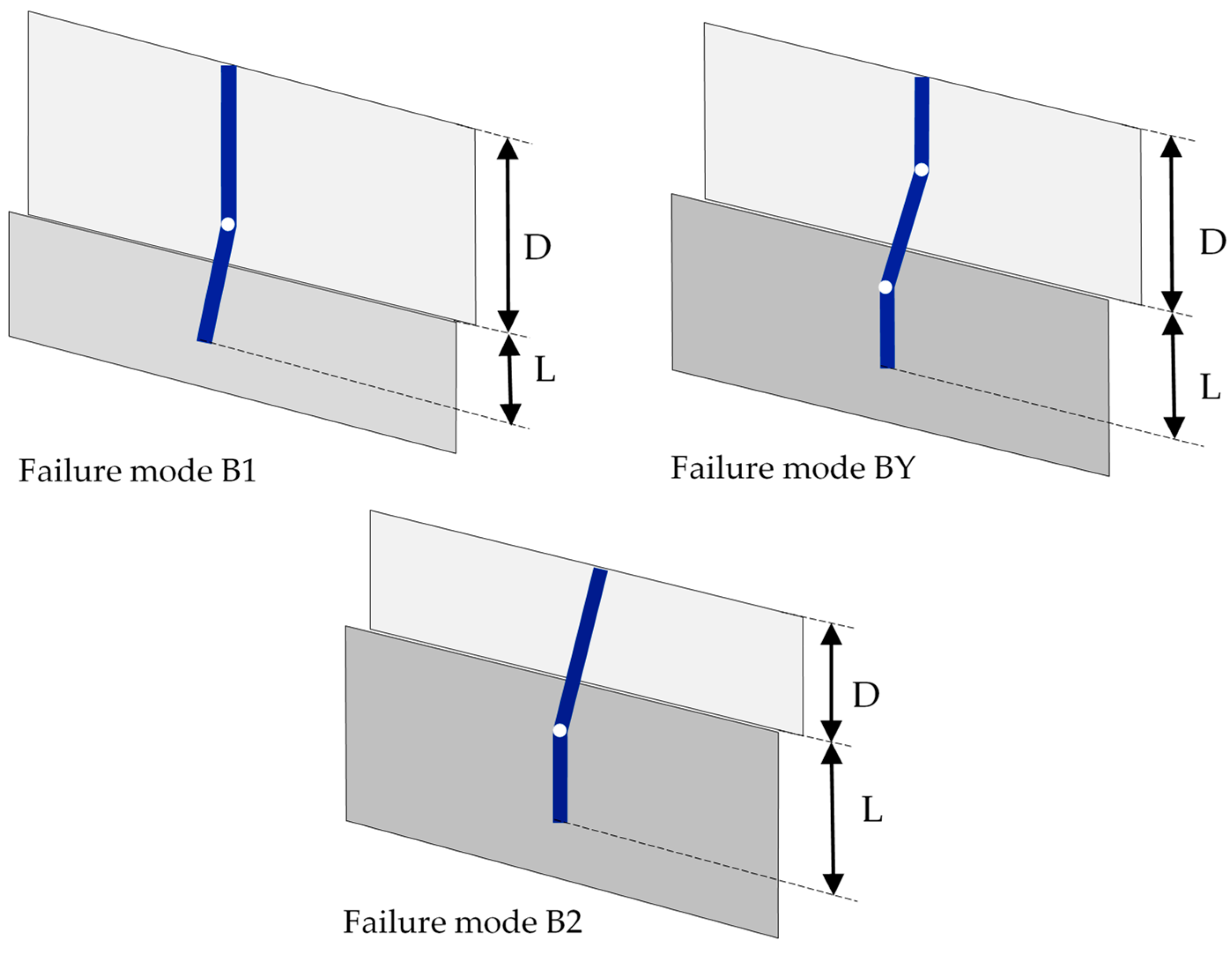
3] examined the case of a free-head single pile embedded in a horizontal translational landslide in which the soil is characterised by undrained strength. The author identified six possible failure mechanisms of the pile–soil system, three of which were related to the case of a pile having infinite stiffness and strength, for which failure is localised in the soil (type A, B, and C), while, in the cases of the other three, the pile collapses through the formation of one or two plastic hinges (type B1, BY, B2).
Another author [
11] made considerations similar to those of [
3] and defined the following failure mechanisms:
- (i)
Flow mode, when the landslide is shallow and the unstable soil becomes plastic and flows around the pile;
- (ii)
Short-pile mode, when the slide is relatively deep and the length of pile in the stable soil is relatively shallow; the sliding soil carries the pile through the stable soil layer and full mobilisation of soil strength in the stable layer occurs;
- (iii)
Intermediate mode, when soil strength in both the unstable and stable soil is fully mobilised along the pile length;
- (iv)
Long pile failure, which occurs when the pile itself yields because the maximum bending moment reaches the yield moment of the pile cross-section; this mode can be associated with any of the three modes of soil failure listed above, although experience suggests that it is most likely to occur with the intermediate mode.
Aside from the collapse mechanisms associated with the ground failure alone, typical of a rigid pile, a reference will be made below to the failure mechanisms of free-head flexible single piles. This is in order to investigate the occurrence of the B1, BY and B2 failure mechanisms as outlined by [
3]: the failure mode B1 occurs with the formation of a plastic hinge along the length in contact with the sliding ground, while the failure mode B2 occurs with the formation of a plastic hinge along the length of pile in contact with the stable ground; finally, failure mode BY occurs with the formation of two plastic hinges, one along the pile length in contact with the moving soil and the other along the pile length in contact with the stable ground (
Figure 1).
In this paper, some 3D numerical models of free-head flexible single piles are analysed with reference to a translational landslide of thickness D and angle of inclination β. The study is limited to a one large-diameter concrete pile, 1200 mm in diameter and total length, D + L, with the aim of studying the collapse modes B1, BY and B2, typical of free-head flexible piles approaching collapse with the formation of plastic hinges.
The aim of this investigation is to apply the design criteria provided by the Eurocode for reinforced concrete elements and to appreciate the main characteristics of the soil–structure interaction during the landslide displacements. One of these aspects is related to the non-isochronism with which shear and bending strengths are mobilised in the pile, as well as the role of the displacements necessary to reach both yielding and collapse under bending. Other aspects examined are the mobilisation of the net soil pressure when collapse under bending is reached, as well as the influence of the mobilised normal stress on the overall shear strength offered by the pile along the sliding surface of the slope.
2. The Numerical Models
In order to investigate the interaction process of a free-head concrete single-pile bored in a sliding ground, a finite element model of translational landslide is proposed.
A layer of uniform soil, with a thickness of D, can slide over a stable one along a sliding surface inclined with an angle, β. The reinforced concrete pile has a constant diameter, d, and extends for a length, L, inside the stable soil, for a total pile length of D + L. Displacements are imposed on the upper layer in steps, along a direction parallel to the sliding surface.
Slope reinforcement using free-head vertical single piles involves a model mesh in which the pile is not influenced by the presence of adjacent piles. Therefore, in order to avoid the development of any arch effect between the piles, both the transversal and the longitudinal symmetry planes are located at sufficiently long distances of more than 4 and 6 diameters of pile, respectively [
23].
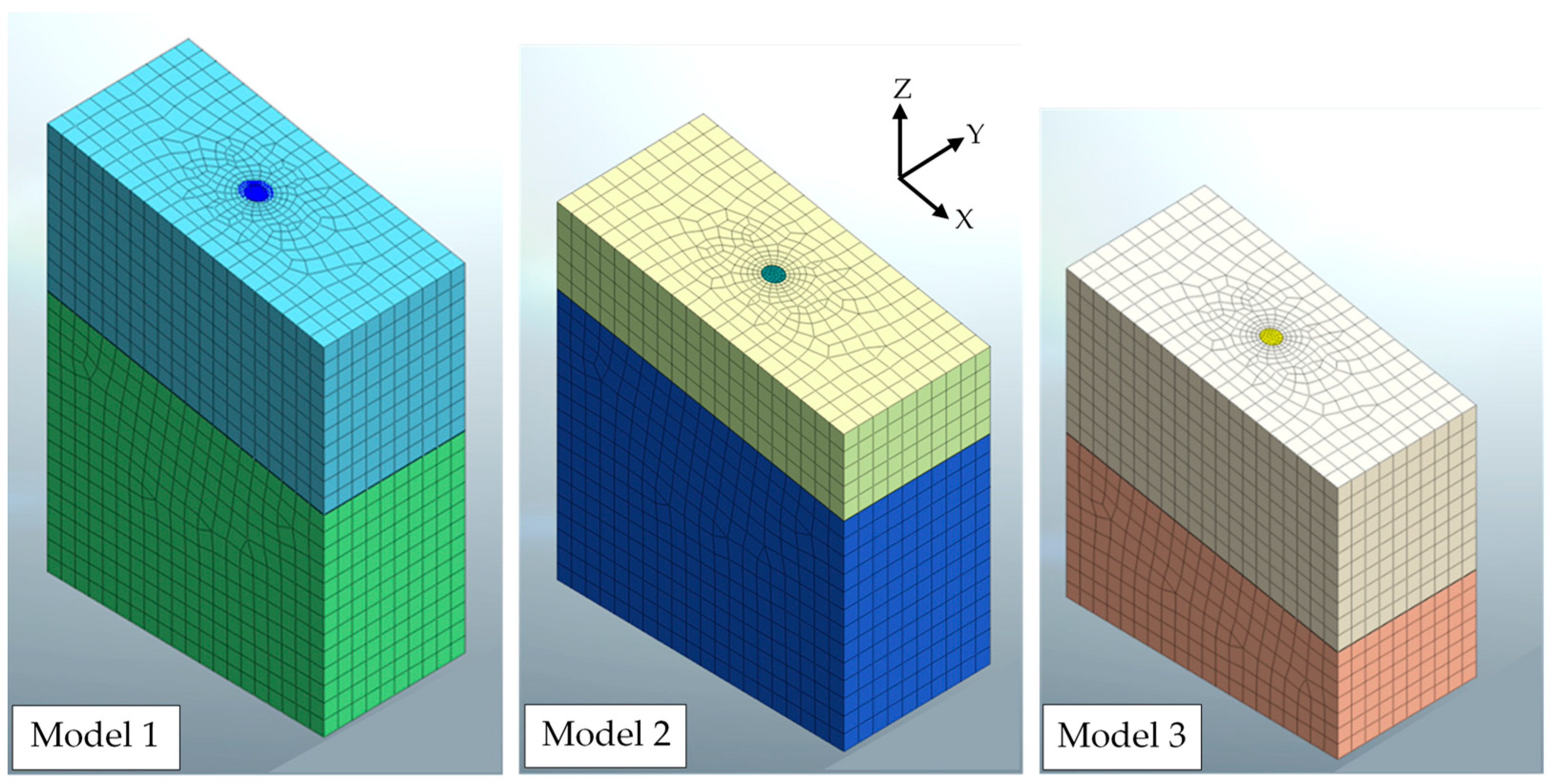
Three different geometries have been studied in order to highlight the failure modes outlined by [
3]: Model 1 should fail based on failure mode BY, Model 2 should fail based on failure mode B2, and Model 3 should fail based on failure mode B1 (
Figure 2). The synthesis of the geometries of the numerical models considered is reported in
Table 1.
The slip surface between the two soil blocks and the separation surface between the pile and the ground are modelled with the aid of interface elements, in order to create localised discontinuities and to favour the relative displacement between the pile and the ground. These elements of virtual thickness are characterised by both normal and tangential stiffness and by shear strength.
To reproduce the different parts of the model, three-dimensional brick elements implemented in MIDAS FEA NX 2021 v1.1 code have been used. These elements have several advantages, including a more stable numerical performance and a reduction in the number of degrees of freedom (three degrees per node). In MIDAS, pile modelling is also supported via the virtual beam function, which allows a quick representation of the stress diagrams in the pile, as well as the displacements of the pile axis.
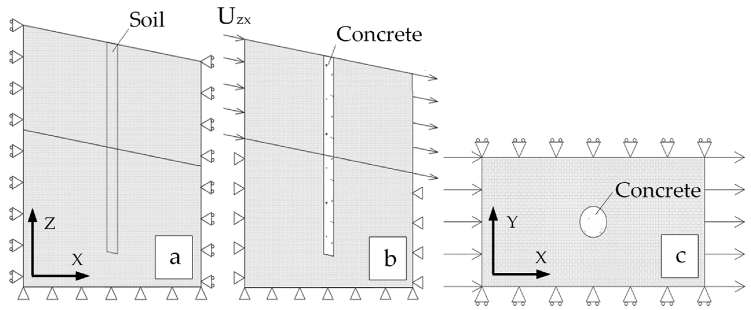
It is necessary to adopt two different constraint conditions: in the first phase, hinges are applied only at the base of the model, whereas at the lateral boundaries displacements are blocked along both the axes X and Y, so that only the compression of the mesh is allowed to occur along the vertical axis, Z.
In the second phase, hinges are applied both to the base and to the sides of the underlying stable formation, while on the sides of the above unstable formation the displacement is blocked only along the Y axis, while it is allowed along the slip plane direction, in terms of displacement vectors Uzx with components along Z and X.
In the first phase of the analysis, the initial state of equilibrium is sought (
Figure 3a): the soil parameters are attributed to the whole model, including the elements schematising the pile, and a homogeneous compression of the model is carried out under the gravity.
In the next phase (
Figure 3b), the concrete properties are assigned to the pile elements and then displacements U
zx are applied in steps until the calculation process converges.
3. Materials and Method
The ground hypothesised in the simulations is a medium-dense clay with a volume weight of γ = 20 kN/m3, unaffected by the presence of the groundwater.
The simple failure criterion of Mohr–Coulomb has been introduced in the analyses for soil, by considering effective parameters of cohesion c′, friction angle φ′, normal stress σ′, and non-associated flow rule (ψ = 0). Before failure, the soil has a linear elastic behaviour characterised by a longitudinal stiffness modulus Es and Poisson’s ratio ν.
In some cases, the stiffness modulus of the upper soil is differentiated from the lower one in order to highlight the influence of the soil stiffness on the displacement levels. For the same reason, the shear strength parameters of both the sliding and the stable soils are differentiated in some cases.
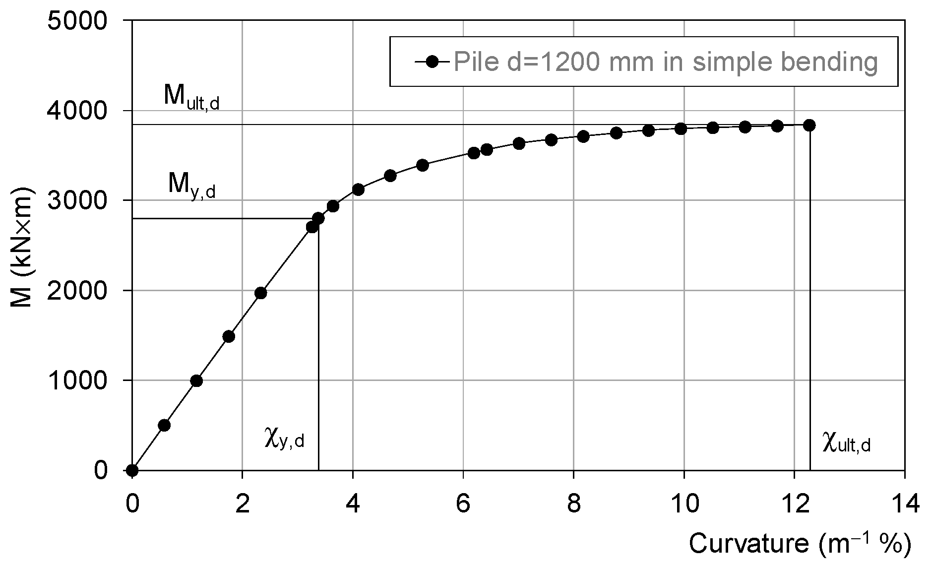
The pile, 1200 mm in diameter, is made of concrete C25/30, with characteristic cylindrical strength fck = 25 MPa, characteristic cubic strength Rck = 30 MPa and design compression strength fc,d = 14.16 MPa. A maximum longitudinal steel reinforcement, B450C, is arranged inside the pile cross section, made up of 28 Ø 32 mm, with a design strength of fy,d = 391.30 MPa, a concrete cover of 50 mm in thickness and a gap distance of 90 mm between reinforcements.
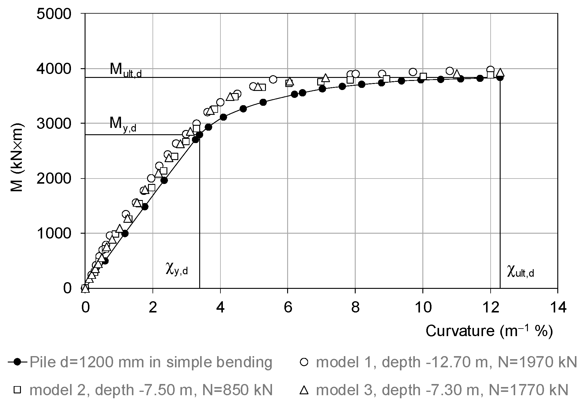
Under these conditions, the design’s simple-bending moments at yield and at failure are, respectively, M
y,d = 2800 kN × m and M
ult,d = 3840 kN × m (
Figure 4).
In addition to longitudinal reinforcement, a transverse spiral stirrup, B450C, 16 mm in diameter and with a pitch of 180 mm, is considered.
The shear strength has been evaluated with different approaches, such as that suggested by [
24] for reinforced rectangular cross-sections subjected to shear-compression or shear-tensile and with the simplified expression proposed by [
25], specifically calibrated for a reinforced circular cross-section. The results of the different calculation criteria appear quite homogeneous; the most conservative method comes from the approach put forward by [
25] according to which the design shear strength is evaluated through the expression:
where:
d = pile diameter (mm);
ρl = Asl/Ac;
Asl = total cross-section area of the longitudinal reinforcement;
Ac = pile cross-section area;
fck = characteristic cylindrical strength of the concrete (MPa);
ρw = Asw/(s × d);
Asw = twice the cross-section area of the Ø 16 mm spiral stirrup (mm2);
s = pitch of the spiral stirrup (mm).
Under these assumptions, the design shear strength is Vult,d ≅ 1770 kN and represents, more or less, the maximum pile shear strength achievable for the pile under investigation, which is considerably reinforced.
In order to discretise the reinforced concrete pile with brick elements, a simplified approach is introduced by considering an equivalent elastic-perfectly plastic material which can reach failure under compression or tension. The volume weight is γ = 25 kN/m
3 and the design tensile strength, f
t,d, is obtained from the ratio of the cross-section areas of both steel and concrete:
The design compressive strength of the pile and its longitudinal modulus of elasticity are assumed coincident with those of a class C25/30 concrete, i.e., fc,d = 14.16 MPa, E = 31,500 MPa and Poisson’s ratio ν = 0.2.
The introduction of the aforementioned simplified constitutive model for the pile, although not able to capture shear failure, allows us to predict with reasonable approximation firstly the displacement of the pile head when the yield moment, My,d, is reached and subsequently the displacement of the pile head when the ultimate moment, Mult,d, is attained in the most stressed cross section of the pile. Therefore, the shear failure mode is detected by comparing the induced shear stress with the pile shear strength (Equation (1)).
The mobilised shear strength along the discontinuity surfaces of the model is simulated by using interface elements arranged along the sliding surface and the pile lateral surface. With these elements, it is possible to reach large displacements along the model discontinuities, as well as to take into account the possible loss of contact between the pile and the ground. The strength of these elements follows the Mohr–Coulomb failure criterion in the case of non-associated flow (ψ = 0). For these elements, it is necessary to define:
The angle of residual strength, φr, along the slip surface;
Soil-pile adhesion a′;
Soil-pile angle of shear strength δ′;
The normal stiffness modulus, Kn;
The shear stiffness modulus Kt.
All parameters and cases considered for the numerical models are summarised in
Table 2.
4. Results of the Analyses and Discussion
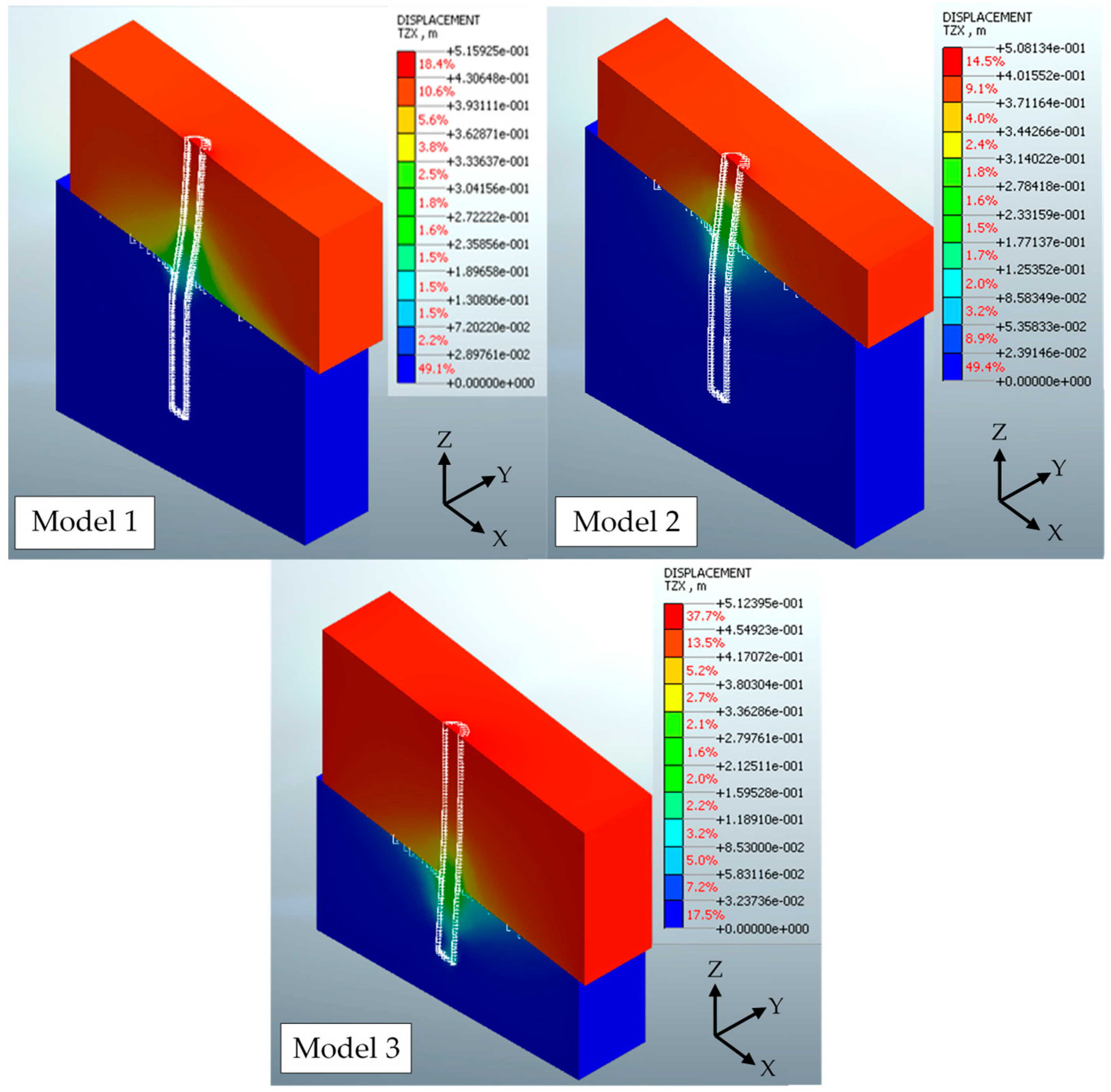
Figure 5 shows the contours of the displacements U
xz of Models 1, 2 and 3 of
Figure 2 in the last converging phases of the analyses. These contours refer to homogeneous models with E
s,sup = E
s,inf = 10,000 kPa, c′ = 100 kPa and φ′ = 20°.
In the vicinity of the pile head, these displacements amount to just over 50 cm and coincide with the displacement of the upper unstable formation. Along the shaft, all the three models show the achievement of the design failure moment in simple bending according to the kinematic mechanisms of type BY for Model 1, of type B2 for Model 2 and of type B1 for Model 3.
The results of the numerical models show that during pile–soil interaction, the concrete first reaches the yield curvature, χy,d, and then the ultimate one, χult,d.
As reported in
Figure 6, the moment–curvature relationships obtained for the most stressed pile sections of the Models 1, 2 and 3 of
Figure 5 are compared with that of the concrete pile cross-section subjected to simple bending. Although the first moment–curvature relationships derive from a simplified constitutive model for concrete, they allow us to outline two representative reference stages of the pile, i.e., the elastic limit and the failure.
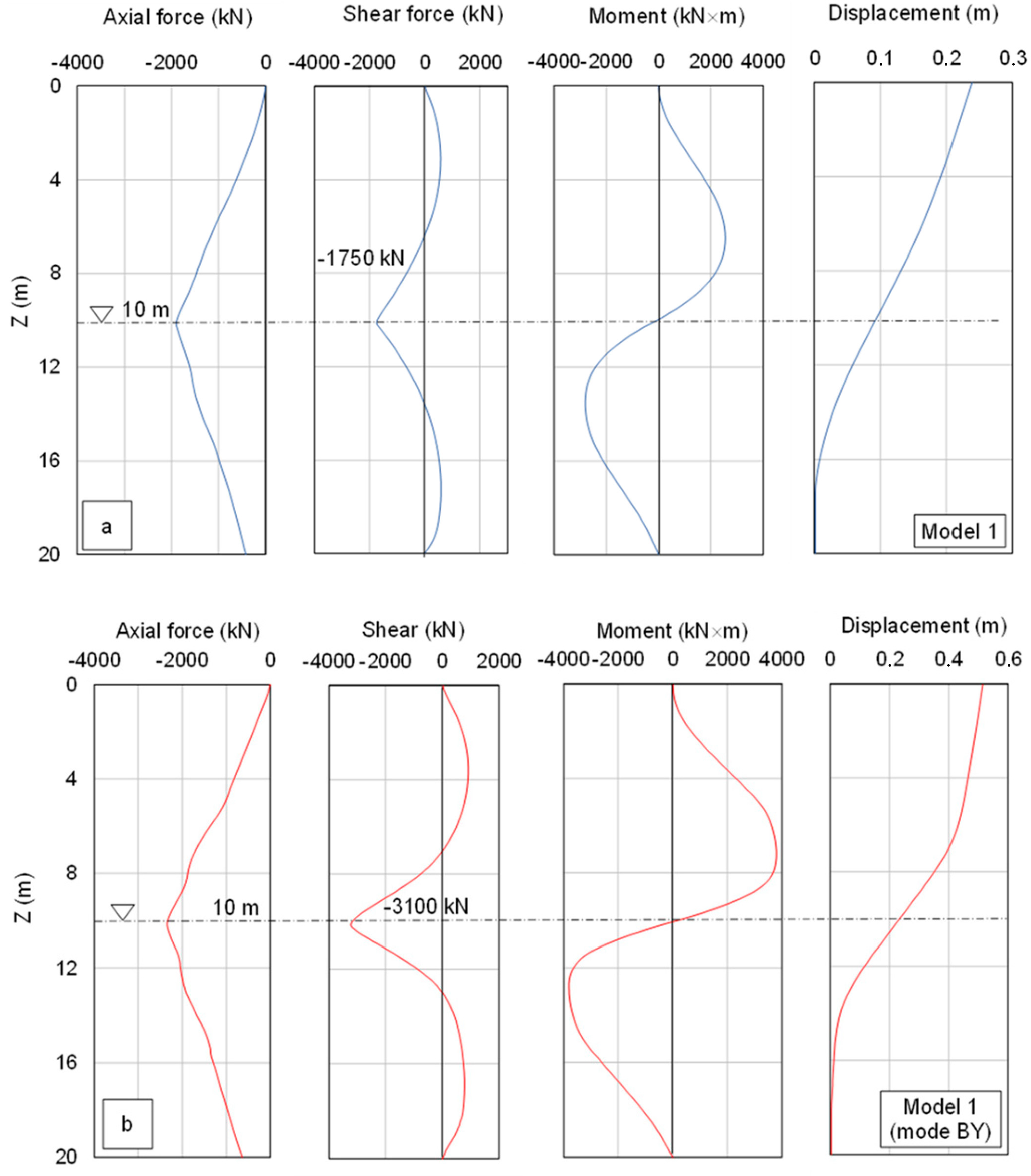
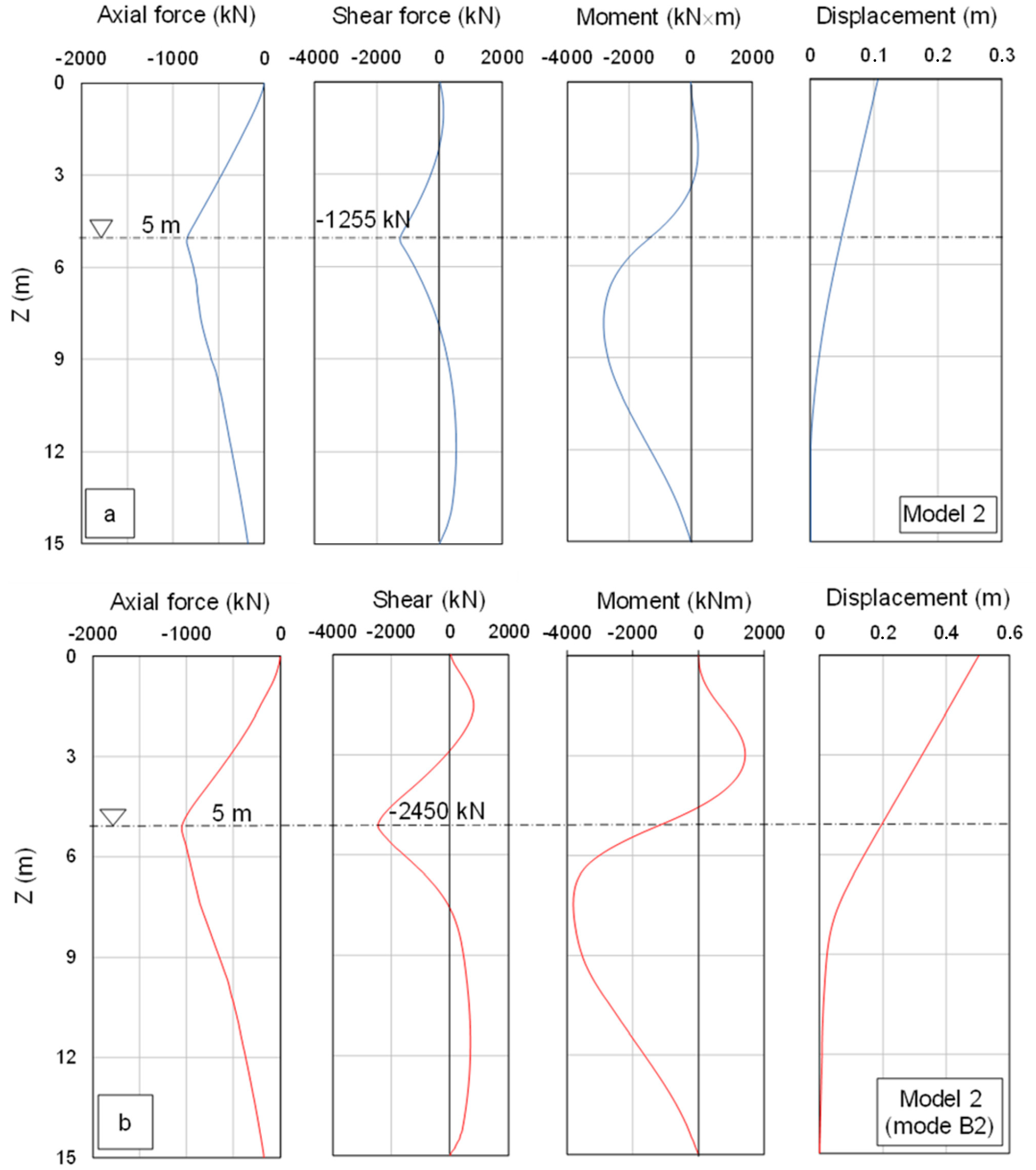
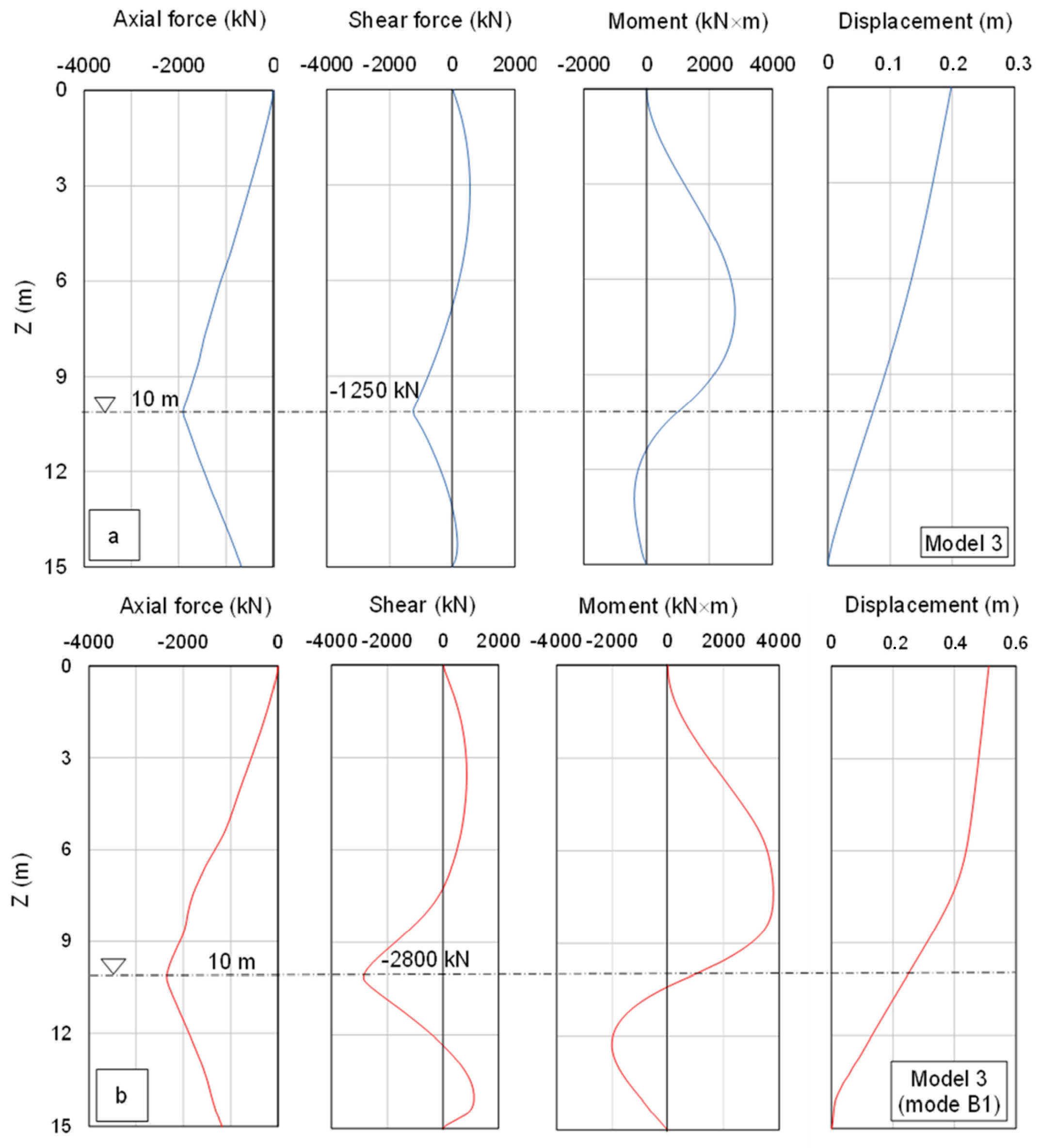
The complete pile–soil interactions for the aforementioned models of
Figure 5 are synthetised in
Figure 7,
Figure 8 and
Figure 9, in terms of normal stress, shear stress, bending moment and horizontal displacement of the pile, both when the yield moment is reached (Model 1
Figure 7a, Model 2
Figure 8a and Model 3
Figure 9a) and when the ultimate moment is achieved in the most stressed cross-section of the pile (Model 1
Figure 7b, Model 2
Figure 8b and Model 3
Figure 9b).
From these distributions, much information of practical interest can be deduced. Firstly, it can be observed that in correspondence to the slip surface the axial load and the shear load are maximum, whereas the bending moment is low, almost close to zero. Therefore, in the stability analyses of translational slopes reinforced with free-head flexible single-piles, it is sufficient to introduce the former two forces for a global stability check.
The normal load can be easily evaluated a priori with the formulas of the static bearing capacity since, even for the modest inclination of the slope considered in this study, the vertical component of the displacement of the upper unstable soil is high enough to mobilise the lateral friction of the pile along the length in contact with the unstable formation itself.
With reference to the ultimate pile condition, attention was paid in the past to the formation of plastic hinges according to the failure modes B1, BY and B2; for these mechanisms, the location of the plastic hinges does not occur at the slip surface but above or below it. On the basis of these failure modes, the shear force offered by the pile at the slip surface level could be predicted by equilibrium [
4].
From the diagrams in
Figure 7b,
Figure 8b and
Figure 9b, it can be seen that when the displacements are pushed up to the design ultimate moment, M
ult,d = 3840 kN × m, the shear load always exceeds the design shear strength, V
ult,d = 1770 kN, at the sliding surface level. It can be deduced that the pile should collapse first in shear rather than for bending moment.
Therefore, in a conventional bored concrete pile, the interaction analysis should be stopped no later than reaching the yield moment M
y,d in the most stressed cross-section, a condition for which all the three pile models reach a shear force lower than V
ult,d (
Figure 7b,
Figure 8b and
Figure 9b). In this latter condition, Model 1 mobilises 99% of the design shear strength (1750/1770) while Model 2 (1255/1770) and Model 3 (1250/1770) mobilise roughly 71%.
Basically, shear failure of the pile near the slip surface could be the most critical condition and would not allow the development of the subsequent mechanisms BY, B1 and B2.
Failure mechanisms of type BY, B1 and B2 could be achieved if further construction solutions aimed at increasing the pile shear strength are sought.
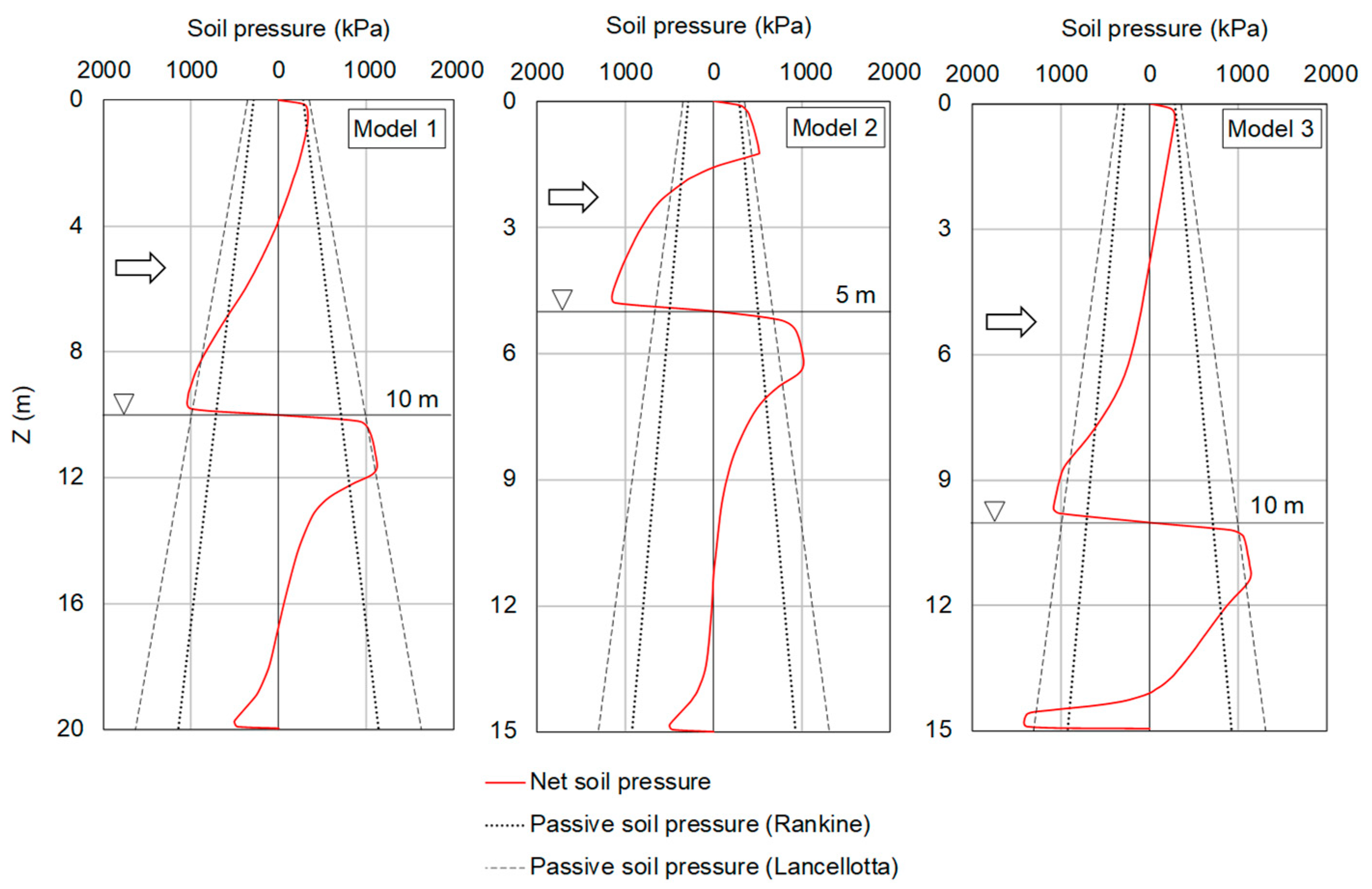
The mean net soil pressure distribution, p(z), acting along the pile diameter, d, is given by the difference between the upstream and the downstream soil pressure distributions.
Moreover, in the hypothesis of constancy of the pile elastic modulus with the progress of the pile curvature, the net load, q(z) = p(z) × d, is linked to both the distributions of shear load, V(z), and bending moment, M(z), through the differential relations:
Figure 10 shows the distributions of the net soil pressures for the three models of
Figure 5 when the ultimate moment in simple bending, M
ult,d, is attained. These distributions are compared with the passive strength solutions of both Rankine [
26] and Lancellotta [
27]. Here, the Lancellotta distribution takes into account a ground friction angle of φ′ = 20°, a cohesion of c′ = 100 kPa, a soil-pile friction angle of δ = 10°, a slope inclination of β = 10° and a passive strength coefficient of K
p ≅ 3, while the Rankine distribution refers to a ground friction angle of φ′ = 20°, a cohesion of c′ = 100 kPa, a soil-pile friction angle of δ = 0°, a slope inclination of β = 0° and a passive strength coefficient of K
p ≅ 2.
It can be seen that the maximum net soil pressure does not exceed the passive strength distribution of Lancellotta, with the only exception of a few parts of the Model 2 in which higher passive soil pressures may be mobilised. This may be a consequence of the three-dimensional interaction, as opposed to the plane-strain condition to which the theories in question refer. In conclusion, it was shown that when the design ultimate moment, Mult,d, is attained in the most stressed pile cross-section, the soil passive pressure is reached in a few limited areas of the pile shaft.
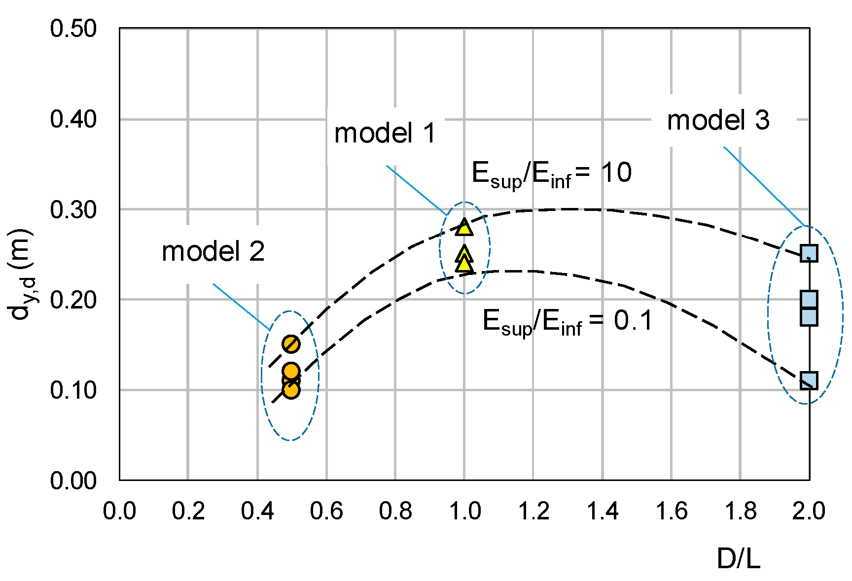
The synthesis of all the examined models is summarised in
Figure 11 in terms of the horizontal pile head displacements, d
y,d, able to induce the design yield moment, M
y,d, in the most stressed cross-section.
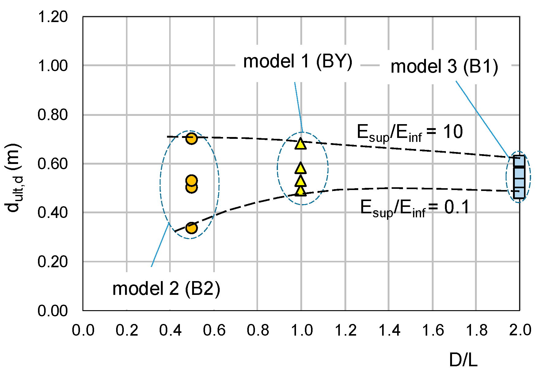
For comparison,
Figure 12 also shows the horizontal pile head displacements, d
ult,d, which cause the design ultimate moment, M
ult,d, to be reached in the most stressed cross-section; this latter representation has meaning only if the pile does not fail before in shear.
The failure modes of the pile depend primarily on the parameter D/L, i.e., on both the lengths, L, in contact with the stable formation, as well as the lengths, D, in contact with the moving ground. The soil stiffness influences the amount of displacement of the pile head but not the mode of deformation. The data in
Figure 11 suggest that the displacements d
y,d causing yielding in simple bending are relatively small, not exceeding 30 cm. For these levels of displacement, the pile may attain at most the design shear strength, V
ult,d, especially in the mode of deformation compliant with Model 1.
If the shear collapse of the pile does not occur first, pile head displacements, less than 70 cm, occur at the ultimate moment in the most stressed pile section; these displacements depend on both D/L and E
sup/E
inf (
Figure 12).
The development of mechanisms BY, B1 and B2, with associated plastic hinges, is less likely to occur in concrete piles if shear failure may occur earlier.
In order to clarify this concept,
Table 3 reports the ratio between the design shear strength and the design simple-bending strength, V
ult,d/M
ult,d, for concrete piles with different diameters, the cross-section being characterised by a percentage of longitudinal reinforcement between 1% and 2%. A spiral stirrup, Ø 16 mm/180 mm, is assumed to be constant in all cases.
What is noticeable is how this ratio tends to decrease as the pile diameter increases, confirming that, under a same kind of kinematics, the shear strength of standard concrete piles can be reached before the simple-bending strength.
5. A Comparison with a Real Case of Reactivated Quiescent Landslide in Stiff Soil
The data in
Figure 11 suggest that the displacements d
y,d causing yielding for bending are relatively small, not exceeding 30 cm; for these levels of displacement, the pile may attain the design shear strength, V
ult,d, especially in the mode of deformation compliant with the Model 1.
A situation of this type has been reported in a case study regarding the stabilisation of the Tusa landslide in Sicily (Italy), in which a layer of altered clay was sliding above the stable formation of scaly clay [
28]. Both formations were made up of 70% clay, 20% silt and 10% sand. The laboratory tests provided an average liquidity limit of 55%, an average plastic limit of 20% and an average plasticity index of 35%. The angle of shear strength obtained both from direct shear tests and from triaxial tests was about 18° and the effective cohesion on average c′ = 30 kPa. For the given soil plasticity and clayey fraction, the residual angle of shear strength could have reached a value of about 10°–12° during the landslide reactivation.
For stabilisation purposes, an instrumented drilled pile 1200 mm in diameter, 22 m in length, reinforced with 18 Ø 24 and equipped with an inclinometer tube, was installed. The slip surface was localised at a depth of about 10 m from the surface and the groundwater level was identified well below the slip surface. After 85 days from the pile casting, the inclinometer indicated a displacement of the pile head of approximately 3.5 cm. Between 18 February 1988 and 7 April 1988, the displacement reached 28.5 cm, with an increase in approximately 25 cm over 50 days. In these conditions, the pile showed collapse just near the sliding surface.
This case study seems to support the results of this study: since the pile and the soil were almost compliant with the numerical Model 1, the pile should have undergone a BY-type of collapse mechanism with the formation of two plastic hinges. Instead, it collapsed in shear near the slip surface with a final displacement of the pile head of 28.5 cm.
6. Strength of a Free-Head Pile Restraining a Translational Landslide
The current design approach for a translational landslide stabilisation with free-head flexible single piles involves the following steps:
- (i)
an evaluation of the integrative shear strength along the sliding surface of the ground volume pertaining to the single pile to obtain a given safety factor;
- (ii)
a sizing of the single pile to give the requested design shear strength.
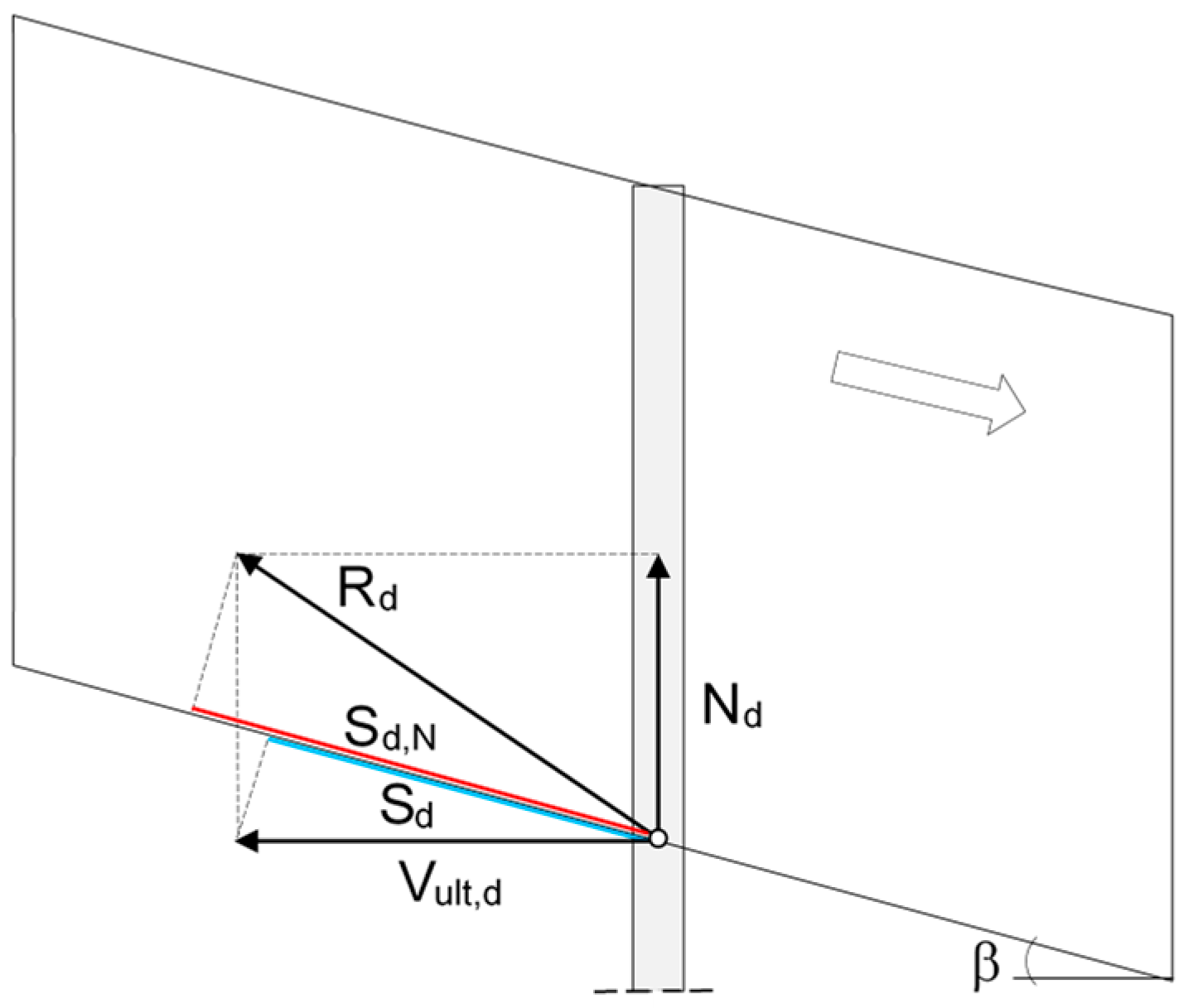
The total strength offered by a single pile at the slip surface level is R
d (
Figure 13) and results from the composition of the design normal stress, N
d, and the design shear strength, V
ult,d. This is because, as indicated by the results of the numerical analyses, a significant amount of axial load is mobilised by the pile in proximity to the sliding surface, even for limited soil displacements along the slope.
The component of R
d along the sliding surface is:
If, however, the contribution of the axial load is ignored, the design strength offered by a single pile along the slip surface becomes:
The ratio, μ, between the two previous strengths, indicates the gain in strength offered by the pile along the slip surface if the axial load is taken into account:
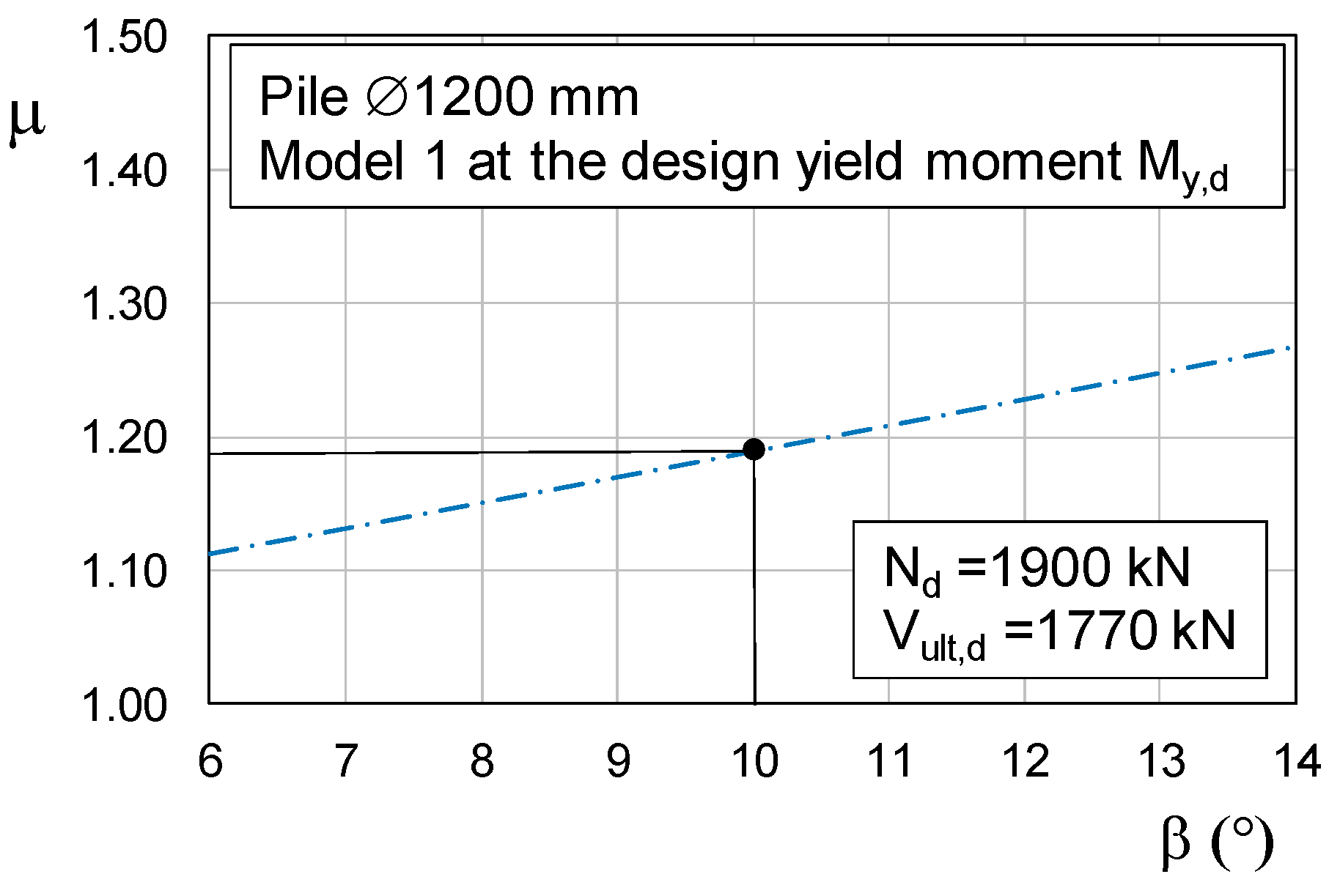
For example, the pile of Model 1 of
Figure 7a shows an axial load N
d = 1900 kN when the design yield moment, M
y,d, is reached and the shear stress approaches V
ult,d = 1770 kN. This axial load can be combined with the design shear strength to give a strength ratio of μ = 1.19 (Equation (6)), that is a gain in strength of about 19%. For this combination of forces,
Figure 14 shows the variation in the μ with the slope inclination variable just around the design value β = 10°.
7. Conclusions
This study has aimed to advance some practical considerations in the design of single free-head piles for the stabilisation of shallow translational landslides, such as in the case of quiescent landslides in stiff formations that may undergo reactivation. On account of this, only the failure modes involving the formation of plastic hinges in the pile have been considered.
The model pile, 1200 mm in diameter, is embedded in landslide with a thickness of D and an inclination of β = 10°. It has a total length of D + L, in order to study the collapse modes B1, BY and B2 as defined by some previous studies on flexible pile [
3,
11]. For this purpose, some 3D FEM numerical models have been built, and simplified constitutive models have been implemented for both the soil (Mohr–Coulomb) and the pile (elastic-perfectly plastic), in order to apply the practical design approaches provided by Eurocode [
23] for reinforced concrete.
The main results obtained are the following:
All the numerical models show maximum values of both shear stress, Vd, and normal stress, Nd, at the slip surface, whereas their bending moment is here low or negligible;
Unless particular structural solutions are used, the classic arrangement of the reinforcements in a large diameter pile implies that the design shear strength of the pile, Vult,d, is reached sooner than the simple-bending strength, Mult,d, even for piles with a diameter greater than that considered in this study and with a comparable percentage of reinforcement. This means that the mechanisms BY, B1 and B2, associated with the formation of plastic hinges, could be preceded by a shear failure mechanism. Therefore, if particular solutions aimed to increase the shear strength of a bored pile are not envisaged, it might be more appropriate to limit the pile–soil interaction until the yield moment, My,d, is reached, so that the shear force mobilised in the pile does not exceed the ultimate design shear resistance, Vult,d;
For the piles under study, the head displacements necessary to reach the design yielding moment, My,d, in the most stressed cross-section, are as low as 30 cm, whereas those necessary to reach the design collapse moment, Mult,d, do not exceed 70 cm. These displacements may vary in the function of both D/L and Esup/Einf ratios;
The strength offered by a pile is provided not only by the design shear strength, but also by the design normal load due to the lateral friction developing along the pile length D when in contact with the moving ground. This axial load could be mobilised even for small slope inclinations (β = 10° in this case) and for horizontal displacements of the pile head compatible with those required for reaching the design yielding moment, My,d, in the most stressed cross-section;
Finally, in a free-head flexible pile, the net soil pressure reaches the limiting passive pressure only in limited sections of the pile.


