
BIZON–UGV for Airport Pavement Testing: Mechanics and Control

 ,
,  and
and
Abstract
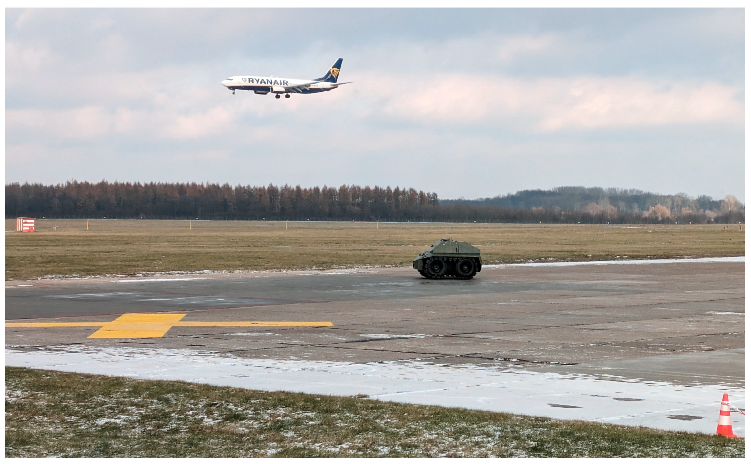
:1. Introduction
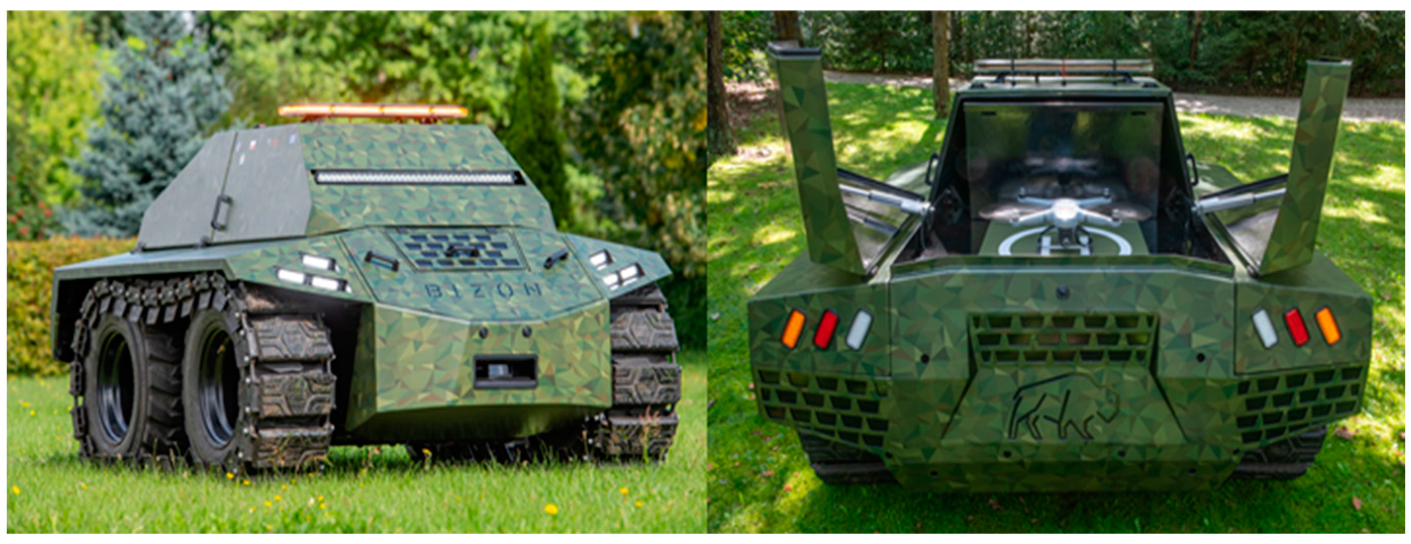
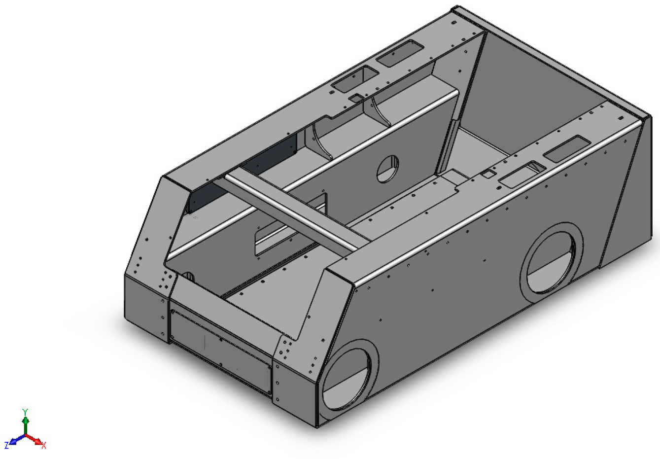
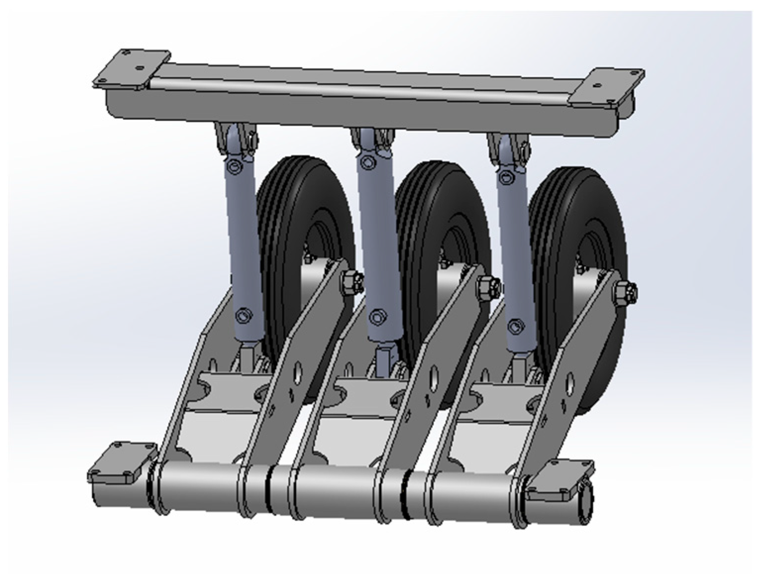
2. Mechanical Design and Analysis
2.1. Methodology
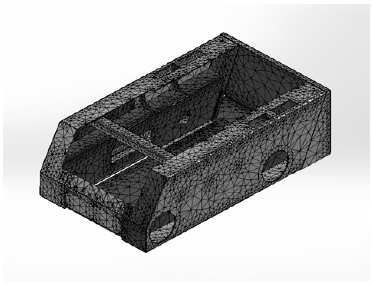
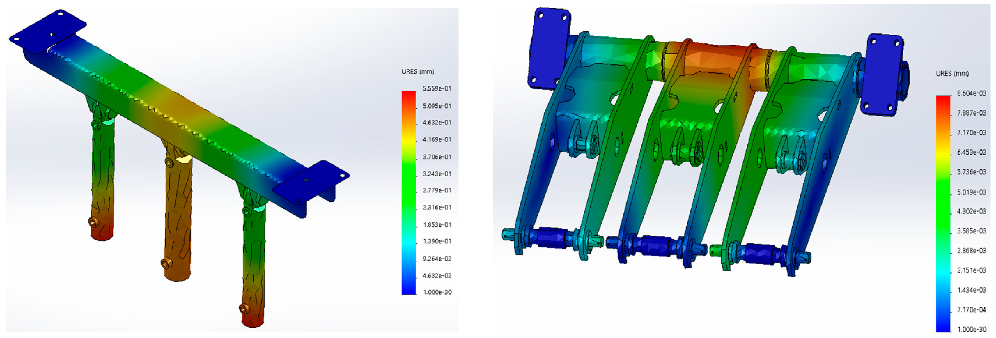
2.2. Numerical Analysis
3. Modelling and Control
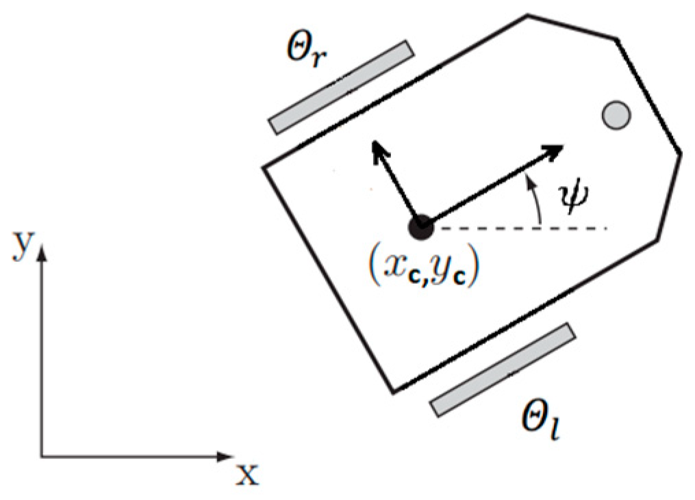
3.1. Mathematical Model
- ,
- ,
- ,
- .
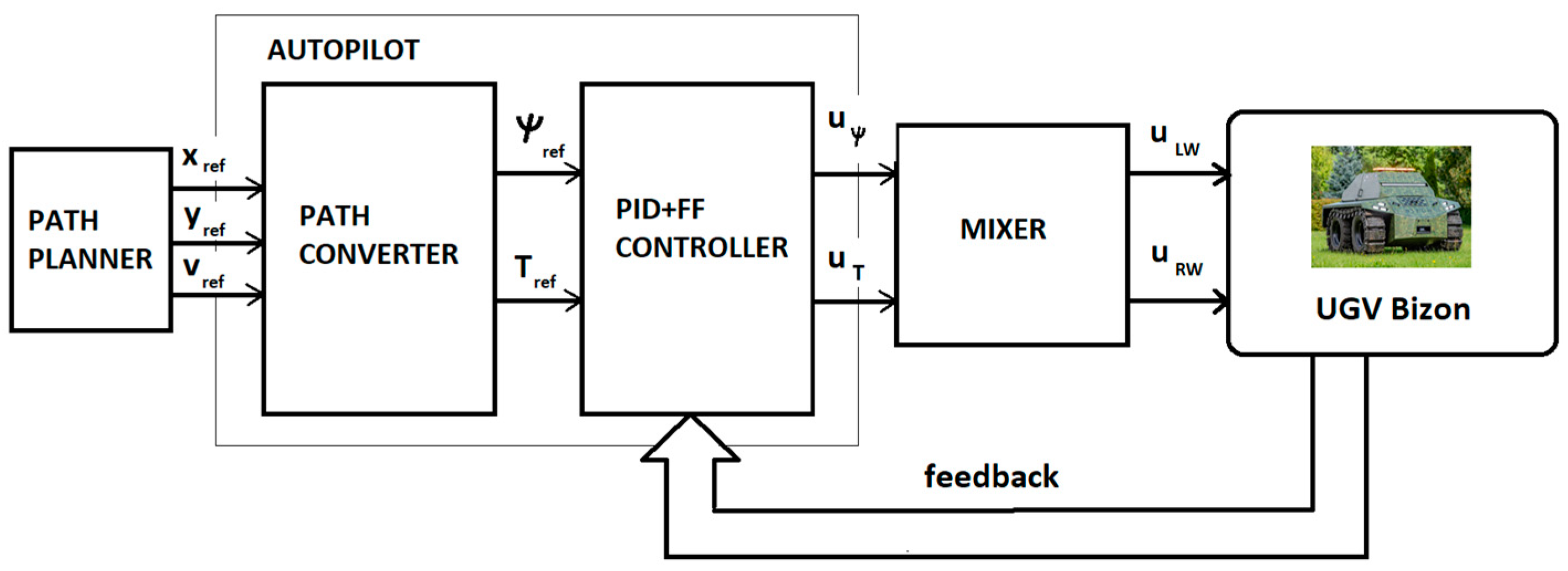
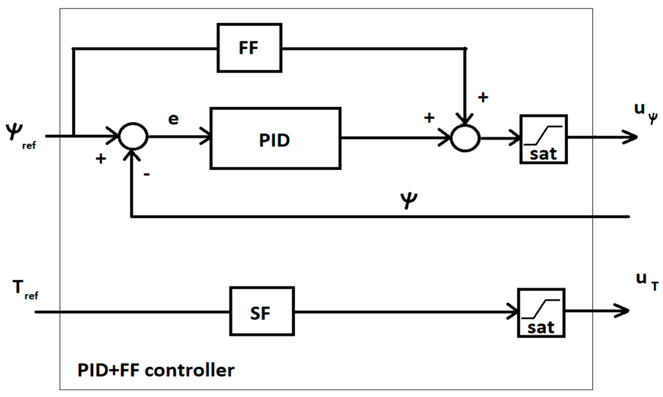
3.2. Control System and Autopilot Design
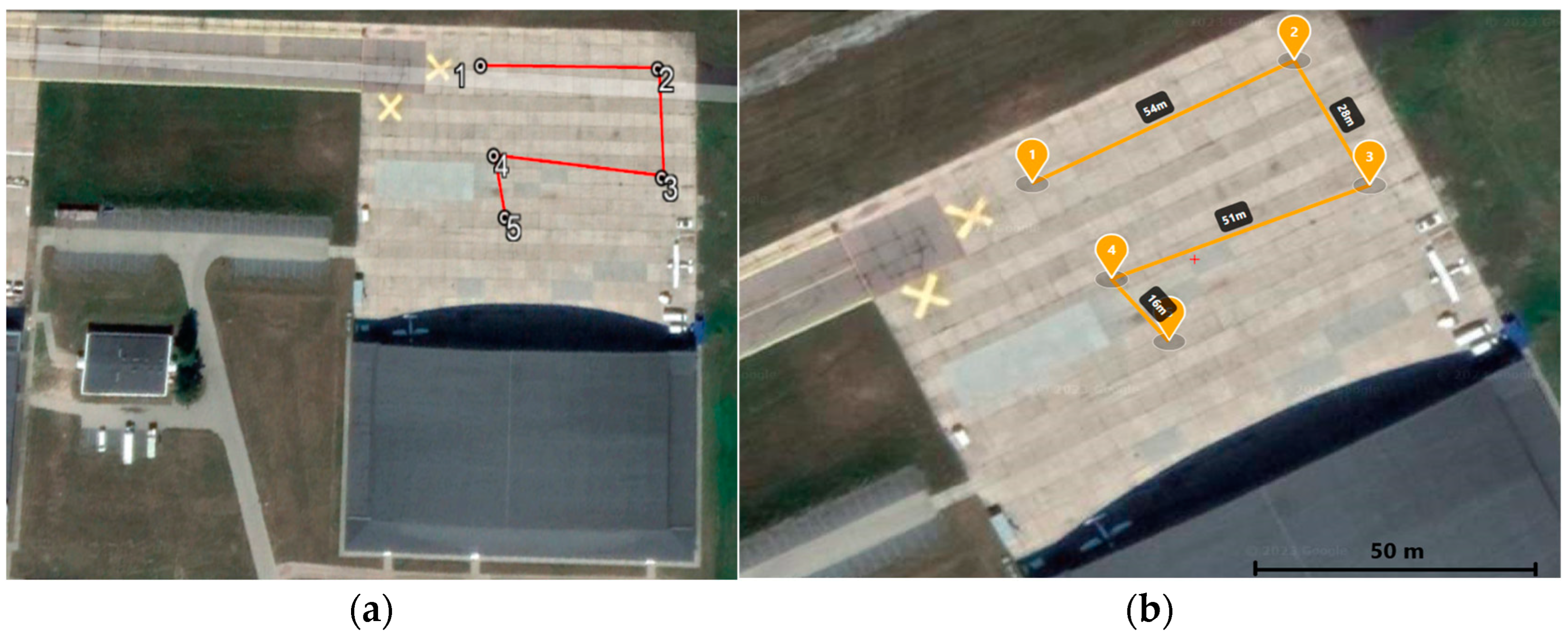
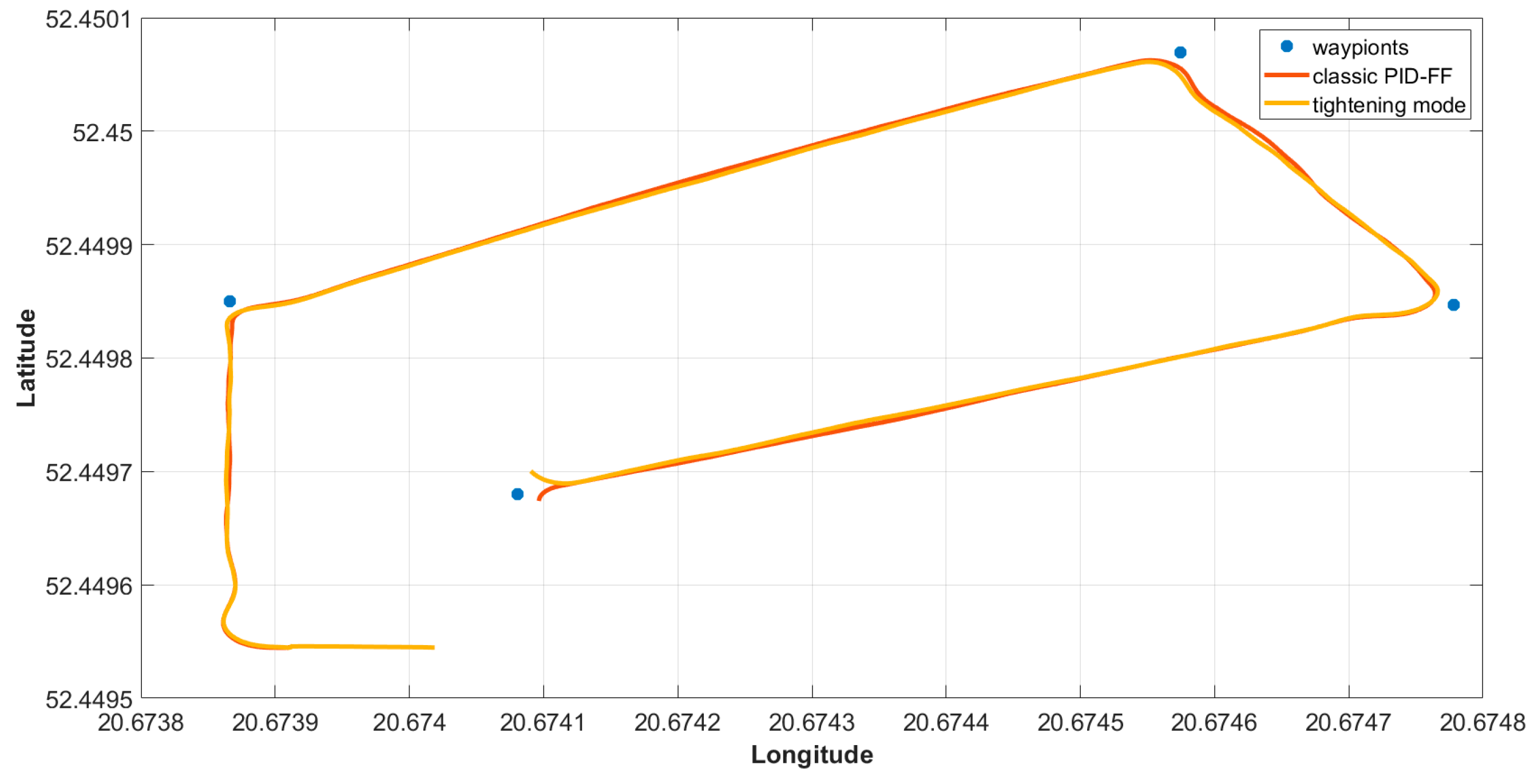
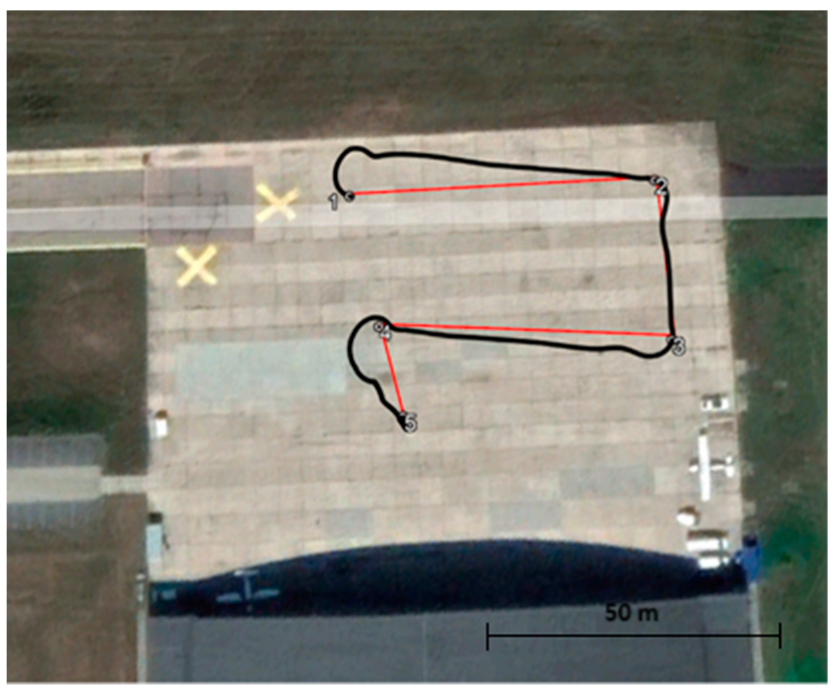
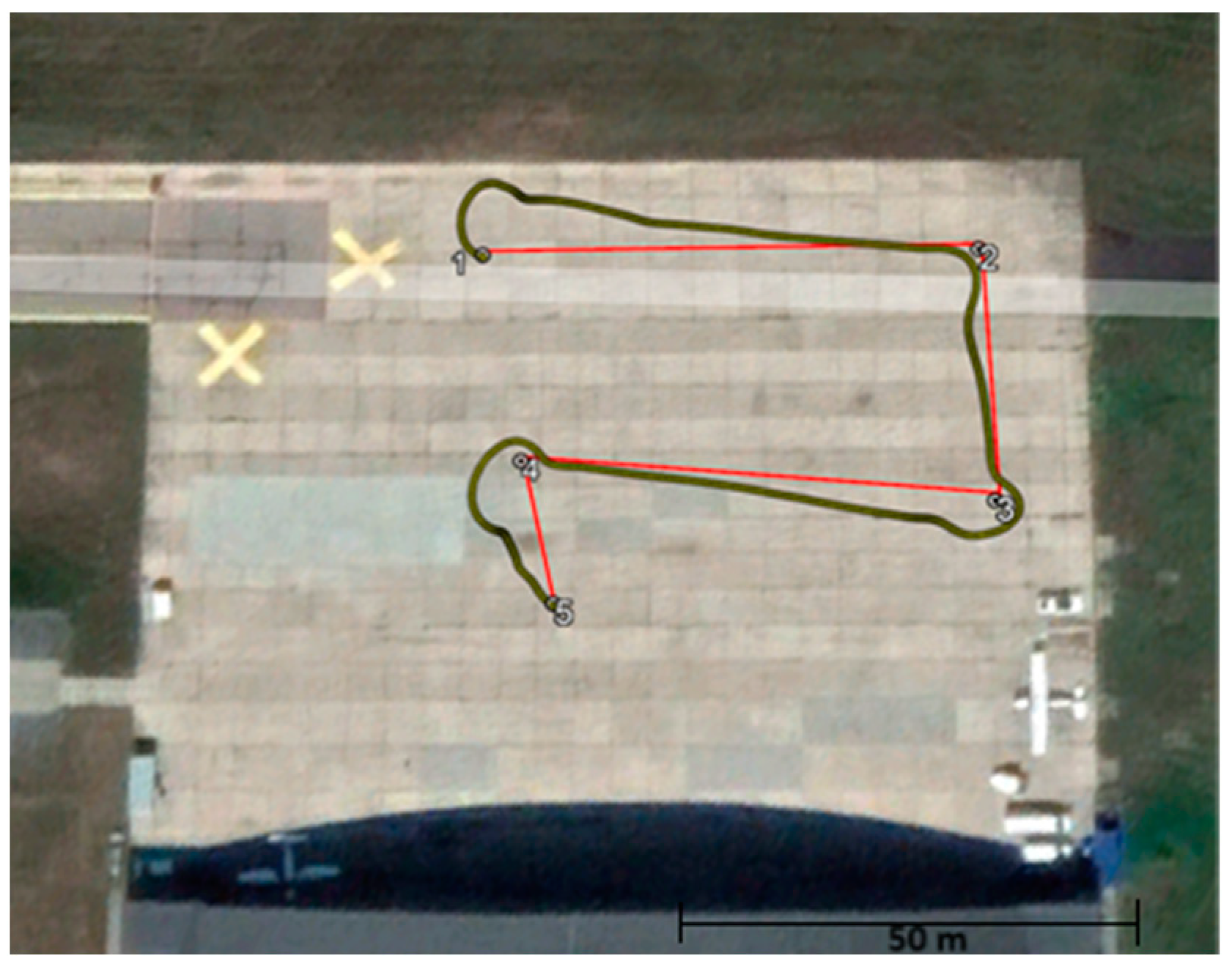
3.3. Experiment and Measurement
- (a)
- typical PID-FF trajectory control;
- (b)
- the PID-FF with tightening to the trajectory.
4. Conclusions
Author Contributions
Funding
Institutional Review Board Statement
Informed Consent Statement
Data Availability Statement
Acknowledgments
Conflicts of Interest
References
- Singh, S. The DARPA Urban Challenge: Autonomous Vehicles in City Traffic; Springer: Berlin/Heidelberg, Germany, 2009; Volume 11. [Google Scholar]
- Naranjo, J.E.; Clavijo, M.; Jimenez, F.; Gomez, O.; Rivera, J.L.; Anguita, M. Autonomous vehicle for surveillance missions in off-road environment. In Proceedings of the IV IEEE Intelligent Vehicles Symposium, Gothenburg, Sweden, 19–22 June 2016; pp. 98–103. [Google Scholar]
- Pazderski, D. Waypoint Following for Differentially Driven Wheeled Robots with Limited Velocity Perturbations. Asymptotic and Practical Stabilization Using Transverse Function Approach. J. Intell. Robot. Syst. 2017, 85, 1–23. [Google Scholar] [CrossRef]
- Tseng, Y.-H.; Kang, S.-C.; Chang, J.-R.; Lee, C.-H. Strategies for autonomous robots to inspect pavement distresses. Autom. Constr. 2011, 20, 1156–1172. [Google Scholar] [CrossRef]
- Chang, J.-R.; Tseng, Y.-H.; Kang, S.-C.; Tseng, C.-H.; Wu, P.-H. The Study in Using an Autonomous Robot for Pavement Inspection. In Proceedings of the 24th International Symposium on Automation and Robotics in Construction, Kochi, India, 19–21 September 2007; pp. 229–234. [Google Scholar]
- Nowakowski, M. Perception technology for conversion of off-road vehicles for the purposes of unmanned missions. J. Civ. Eng. Transp. 2023, 5, 15–27. [Google Scholar] [CrossRef]
- Kelner, J.M.; Burzynski, W.; Stecz, W. Modeling UAV swarm flight trajectories using Rapidly-exploring Random Tree algorithm. J. King Saud. Univ.-Comput. Inf. Sci. 2024, 36, 101909. [Google Scholar] [CrossRef]
- Mei, A.; Zampetti, E.; Di Mascio, P.; Fontinovo, G.; Papa, P.; D’Andrea, A. ROADS—Rover for Bituminous Pavement Distress Survey: An Unmanned Ground Vehicle (UGV) Prototype for Pavement Distress Evaluation. Sensors 2022, 22, 3414. [Google Scholar] [CrossRef] [PubMed]
- Coenen, T.B.; Golroo, A. A review on automated pavement distress detection methods. Cogent Eng. 2017, 4, 1374822. [Google Scholar] [CrossRef]
- Kim, T.; Ryu, S.K. Review and analysis of pothole detection methods. J. Emerg. Trends Comput. Inf. Sci. 2014, 5, 603–608. [Google Scholar]
- Yu, B.X.; Yu, X. Vibration-based system for pavement condition evaluation. In Applications of Advanced Technology in Transportation; ASCE: Reston, VA, USA, 2006; pp. 183–189. [Google Scholar]
- Eriksson, J.; Girod, L.; Hull, B.; Newton, R.; Madden, S.; Balakrishnan, H. The pothole patrol: Using a mobile sensor network for road surface monitoring. In Proceedings of the 6th International Conference on Mobile Systems, Applications, and Services, Breckenridge, CO, USA, 17–20 June 2008; pp. 29–39. [Google Scholar]
- Buza EOmanovic, S.; Huseinovic, A. Pothole detection with image processing and spectral clustering. In Proceedings of the 2nd International Conference on Information Technology and Computer Networks, Mathura, India, 9–10 March 2013; Volume 810, p. 4853. [Google Scholar]
- Zhang, Z.; Ai, X.; Chan, C.K.; Dahnoun, N. An efficient algorithm for pothole detection using stereo vision. In Proceedings of the 2014 IEEE International Conference on Acoustics, Speech and Signal Processing (ICASSP), Florence, Italy, 4–9 May 2014; pp. 564–568. [Google Scholar]
- Korayem, M.H.; Nekoo, S.R.; Korayem, A.H. Finite time SDRE control design for mobile robots with differential wheels. J. Mech. Sci. Technol. 2016, 30, 4353–4361. [Google Scholar] [CrossRef]
- Akin, J. (Ed.) Finite Element Analysis Concepts via SolidWorks; World Scientific: Singapore, 2009. [Google Scholar]
- Kurowski, P.M. Engineering Analysis with SW Simulation Professional 2006; SDC Publishing: Mission, KS, USA, 2006. [Google Scholar]
- Dohrmann, C.R.; Key, S.W.; Heinstein, M.W.; Jung, J. A least squares approach for uniform strain triangular and tetrahedral finite elements. Int. J. Numer. Methods Eng. 1998, 42, 1181–1197. [Google Scholar] [CrossRef]
- Puso, M.A.; Solberg, J. A formulation and analysis of a stabilized nodally integrated tetrahedral. Int. J. Numer. Methods Eng. 2006, 67, 841–867. [Google Scholar] [CrossRef]
- Al-Milli, S.; Seneviratne, L.D.; Althoefer, K. Track-terrain modelling and traversability prediction for tracked vehicles on soft terrain. J. Terramechanics 2010, 47, 151–160. [Google Scholar] [CrossRef]
- Liu, C.; Chen, W.H.; Andrews, J. Optimisation based control framework for autonomous vehicles: Algorithm and experiment. In Proceedings of the 2010 International Conference on Mechatronics and Automation (ICMA), Xi’an, China, 4–7 August 2010; pp. 1030–1035. [Google Scholar]
- Wong, J.Y. Theory of Ground Vehicles; John Wiley & Sons: New York, NY, USA, 2008. [Google Scholar]
- Dobrowolski LLC Company. Available online: https://www.dobrowolski.com.pl (accessed on 2 May 2023).
- Air Force Institute of Technology. Available online: https://itwl.pl (accessed on 2 May 2023).
- Silva, F.O.E.; Ferreira, L.H.D.C. Design and implementation of a PID control system for a coaxial two-wheeled mobile robot. In Proceedings of the IEEE International Symposium on Industrial Electronics, Taipei, Taiwan, 28–31 May 2013; pp. 1–6. [Google Scholar]
- Khalaji, A.K.; Moosavian, S.A.A. Stabilization of a tractor-trailer wheeled robot. J. Mech. Sci. Technol. 2016, 30, 421–428. [Google Scholar] [CrossRef]


| Parameter | Value [Quantity] |
|---|---|
| 2000 [kg] | |
| 200 [kg] | |
| 0.6 [m] | |
| 0.5 [m] | |
| 21.2 [kg.m2] | |
| 0.02 [kg.m2] | |
| 0.27 [kg.m2] |
| Point nr. | Geographic Coordinates | Distance between Points [m] | Heading Angle [°] | |
|---|---|---|---|---|
| Latitude | Longitude | |||
| 1 | 52°26′59.461″ N | 20°40′25.917″ E | - | 63.2 |
| 2 | 52°27′0.2500″ N | 20°40′28.467″ E | 54.4 | 151.0 |
| 3 | 52°26′59.449″ N | 20°40′29.201″ E | 28.6 | 248.6 |
| 4 | 52°26′58.849″ N | 20°40′26.691″ E | 51.0 | 140.7 |
| 5 | 52°26′58.446″ N | 20°40′27.240″ E | 16.5 | |
Disclaimer/Publisher’s Note: The statements, opinions and data contained in all publications are solely those of the individual author(s) and contributor(s) and not of MDPI and/or the editor(s). MDPI and/or the editor(s) disclaim responsibility for any injury to people or property resulting from any ideas, methods, instructions or products referred to in the content. |
© 2024 by the authors. Licensee MDPI, Basel, Switzerland. This article is an open access article distributed under the terms and conditions of the Creative Commons Attribution (CC BY) license (https://creativecommons.org/licenses/by/4.0/).
Share and Cite
Chodnicki, M.; Nowakowski, M.; Pietruszewski, P.; Wesołowski, M.; Stępień, S. BIZON–UGV for Airport Pavement Testing: Mechanics and Control. Appl. Sci. 2024, 14, 2472. https://doi.org/10.3390/app14062472
Chodnicki M, Nowakowski M, Pietruszewski P, Wesołowski M, Stępień S. BIZON–UGV for Airport Pavement Testing: Mechanics and Control. Applied Sciences. 2024; 14(6):2472. https://doi.org/10.3390/app14062472
Chicago/Turabian StyleChodnicki, Marcin, Mirosław Nowakowski, Paweł Pietruszewski, Mariusz Wesołowski, and Sławomir Stępień. 2024. "BIZON–UGV for Airport Pavement Testing: Mechanics and Control" Applied Sciences 14, no. 6: 2472. https://doi.org/10.3390/app14062472
APA StyleChodnicki, M., Nowakowski, M., Pietruszewski, P., Wesołowski, M., & Stępień, S. (2024). BIZON–UGV for Airport Pavement Testing: Mechanics and Control. Applied Sciences, 14(6), 2472. https://doi.org/10.3390/app14062472