Abstract
The electric vehicle deployment, due to the plans defined according to the energy transition objectives, produces new challenges for the electrical system. These challenges are associated with the charging infrastructure of these vehicles since they require a high current during specific periods, which can increase losses in the network, overload the lines, or cause voltage drops that affect the system’s stability. To solve these challenges, one of the possible solutions is the investment in new network infrastructure to face the increase in demand, such as the construction of new transformation centers or new medium and low-voltage lines. However, in the case of rural networks with a small number of users, these investments may not be viable. This article analyzes the possible impacts of connecting electric vehicles in a rural low-voltage network located in a Spanish municipality, as well as possible implementable solutions that do not require investment in new infrastructure. The number of connected vehicles has been calculated based on the national plan for 2030, and the network model used is based on actual data provided by the distribution company that operates in the area.
1. Introduction
Global emissions from the transport sector contribute significantly to greenhouse gas emissions, accounting for 24% of direct carbon dioxide (CO2) and playing a substantial role in climate change [1]. Electric vehicles (EVs) using electricity obtained from low-carbon sources can help significantly to reduce CO2 emissions from the transport sector, while decreasing emissions of other air pollutants such as particles and NOx [2,3]. It has also been shown that the emission reductions are maintained regardless of the type of vehicle, sedan, suv or pickup [4]. For these reasons, many countries have adopted measures to encourage using vehicles with more efficient combustion engines (with lower emissions) or electric vehicles. These measures include mainly much more restrictive emission regulations and low-emission zones in major cities [5]. As a result, many automobile manufacturers have begun to emphasize the development of various types of electric vehicles. These include battery electric vehicles, which operate solely on the energy stored in their batteries, and plug-in hybrid vehicles, which run on a combination of battery and combustion engines [6].
From an end-user perspective, there are still barriers to the transition to electric vehicles, such as high prices, limited range and lack of charging infrastructure. To introduce electric vehicles in the transport sector, many countries have set ambitious targets that, combined with the possible increase in the price of fossil fuels in the coming years, will lead to the deployment of electric vehicle technologies [7].
The massive adoption of these vehicles could have an undesirable impact on the electricity system, especially on distribution networks, which would compromise their stability, creating new challenges for distribution system operators [8]. Some authors proposed load-shifting strategies to reschedule electric vehicle charging during periods of lower grid load by controlling the load [9] or even moving charging periods to nighttime [10]. These strategies allow for mitigating the effects on the grid but highlight that policies should be implemented to enable an orderly way of charging electric vehicles, maximizing their penetration while minimizing the impact on the grid.
The possible harmful consequences of massive electrical vehicle deployments would include imbalances between the different phases of the three-phase system, voltage drops, and overloading of network components. Such effects would mostly occur during periods of simultaneous charging of a large number of vehicles due to the limited power that the distribution network can supply [11]. To help grid operators detect and assess potential grid congestion due to the electrification of private vehicles, accurate models are needed to determine the charging energy and power demand of battery electric vehicles with high spatial and temporal resolution. Different approaches to this problem can be found in the literature. The complete decarbonization of Australia’s electricity and transport system was considered by Nadolny et al. [12], detecting a 40% increase in electricity demand with a 4% to 8% increase in the levelized cost of electricity. However, if the effect of charging many vehicles in the afternoon peak period was considered, the average energy price increased by 18%. The effects on city networks were studied by several authors. Dillman et al. [13] developed a model to analyze the potential additional electric load on the Reykjavik power grid due to the integration of electric vehicles (EVs) and according to different pro-EV policies, showing that the power system could face stresses with a potential peak load increase of up to 114% during the study period. Straub et al. [14] propose a novel approach to develop an activity-based model that does not require traffic flow data as input parameters. They use a routing procedure, assigning a destination to each trip based on evaluating all possible destinations based on trip distance and speed, the attractiveness of car access, and the availability of parking spaces. The model was tested in all districts of Berlin, and the results show that peak energy demand can be reduced by up to 31.7% compared to uncontrolled charging.
Adverse effects particularly affect rural grids, as they are generally radial topology grids with a more deteriorated and aging infrastructure compared to urban grids [15]. Rural grids connect consumers spread over a large territory so their cables cross valleys, mountains, and forests. Due to the orography, they are difficult to access for maintenance and repair, which is aggravated by adverse weather conditions. Another problem is that, unlike urban networks, rural networks often lack a communication system. For this reason, distribution system operators cannot remotely solve any eventualities, increasing the time without supply to consumers in the event of a fault [16].
This work aims to study the impact of electric vehicle charging on the low-voltage grid of a Spanish rural community. The study uses actual grid data and consumer demand with an electric vehicle fleet estimated from the forecasts made in the draft of the Spanish National Energy and Climate Plan [17]. Based on the results of the impact on the grid, the work proposes solutions for the mitigation of some of its harmful effects.
This paper is organized as follows: Section 2 depicts the works found in the literature related to EVs in rural and low-voltage networks. Section 3 presents the methodology and the different cases studied in the work, Section 4 shows the results of the simulations with the impact of the EVs charging process, Section 5 proposed some improvements contributing to the stability of the grid and favoring the EV penetration. Finally, Section 6 summarizes the contributions and conclusions.
2. Background
The number of papers covering the impact of EVs in rural areas is much smaller than those dedicated to urban areas. Nevertheless, in the following paragraphs, we will give an overview of what can be found in the literature.
Some authors explore the possibilities of EVs in rural areas, finding that the lack of infrastructure may exclude rural communities from EV development and deployment, contributing to the urban–rural divide [18]. A study of the potential for EVs in rural businesses highlights that rural areas have particular vehicle use and infrastructure characteristics with longer distances and travel times that cause much greater concern for users due to autonomy anxiety [19]. This work concludes that the generalization of EVs in rural businesses needs to improve their cost, performance, and range; moreover, in the current situation, their widespread use would imply changing the organization and planning of companies.
Rural grids are radial and long, often presenting problems of instability and voltage drops at their ends. Several authors studied the use of electric vehicle batteries as storage systems that help improve the stability and reliability of these grids and the penetration of electric vehicles into them. For example, a smartgrid architecture with real-time control integrating different distributed generation technologies and EV charging stations allows for decentralized management while increasing the ability to integrate new distributed energy resources (including EV charging stations) [16]. Yu et al. [20] present a power electronic device featuring multiple AC and DC interfaces and flexible control capability. Based on this system, AC feeders can be converted to symmetric DC feeders by reusing existing transformers and power lines, forming a low-voltage microgrid and increasing the penetration of VE to 352%. Other authors explore cooperative charging of EVs to improve grid stability while increasing EV penetration [21,22]. Xu et al. [23] apply another approach and predict the load demand of EVs in a rural area and optimize charging strategies to smooth demand fluctuations in the network and reduce peak–valley differences while maximizing the economic benefits of participants. Finally, Gschwendtner et al. [24] combines charging control and plug-in behavior, finding that the first has a more significant impact on grid flexibility, but with a minor effect on rural grids.
Regarding simulations, the impact of EV charging on rural grids has been studied using different assumptions, objectives, and methodologies. One of the first works to consider how charging EVs affects rural grid performance through simulation was conducted by Goolsby [25]. He concluded that it was necessary to limit on-peak charging processes so as not to compromise the operation of grid equipment. In addition, the limit determined by the voltage drop is reached earlier than the ampacity limit in rural feeders. Hartvigsson et al. [26] used a synthetic network for the simulations and found that the risks of violating network stability conditions were higher in urban than in peri-urban and rural areas. However, they only considered thermal limits, undervoltage, and overvoltages in the point of connection without considering the effects at the end of the feeders and the imbalances due to the use of single-phase chargers in households. Nacmanson et al. [27] simulated a combination of a detailed high-voltage network with a low-voltage grid, determined from only the number of users, showing that EV penetration can reach up to 80% of residential costumers in urban grids, while rural grids can only sustain 40% penetration. Kurth et al. [28] considered a rural grid with only seven households to simulate the load complementarity of EVs with small photovoltaic (PV) generation systems, demonstrating how the two systems can complement each other to keep the voltage levels of the entire grid within the allowed limits. Among the cases studied, they did not consider the exclusive use of EV chargers without the support of PV systems.
One of the major problems caused by the massive use of single-phase chargers is the appearance of unbalances in the grid and their consequences. They can jeopardize the functionality of the distribution grid, and the effects have been thoroughly examined in [29,30,31]. The key problems include:
- Neutral Conductor Overload. The current through the neutral wire is the sum of the current of the three phases (1). A sufficiently large current can lead to cable heating, degradation, and potential failures [32].
- Distribution Transformer Overheating. The zero-sequence current magnetic flux closes through the oil tank wall of the distribution transformer (DT), resulting in heat generation, increased losses, and reduced equipment lifespan [33].
- Voltage Quality Reduction [34,35].
- Line Losses Increase, caused by neutral line losses and suboptimal distribution of phase currents [36].
- Abnormal vibration and malfunction in induction equipment, such as rotating machines [37,38,39].
- Mal-operation of Protection Relays [39].
- Increase in Neutral to Ground Voltage [32,40].
It is clear that the charging process of electric vehicles in rural networks strongly impacts the network characteristics and can be a barrier to deploying these vehicles. Several authors proposed methods to minimize the impact of imbalances and improve the quality and reliability of the electrical supply. These methods can be categorized into two groups: those based on reconfiguration techniques and those using electronic devices for current compensation [30]. Reconfiguration techniques include the reconfiguration of the distribution feeder, aiming to change the topological structure of the network by altering the state of switches in the distribution feeder [41,42] and the phase balancing technique, which modifies the phase connection between phases through phase swapping [43,44]. The use of electronic devices focusing on current compensation to mitigate the effects is further divided into three progressive approaches. The first is the Increase Nominal Capacity method, which mitigates imbalances by enhancing the nominal power capacity of equipment, such as oversizing protections, distribution transformers, cables, or even separating the neutral conductor [36]. The second approach involves special transformer configurations, utilizing transformers that are more resistant to unbalances, such as the T-connected transformer, Scott transformer, or star-hexagon transformer. Additionally, active filters can be added to the DT [39,45,46,47]. Lastly, the Shunt Active Power Filter (APF) method aims to reduce imbalances by installing shunt APFs with commonly used topologies, including three single-phase H-bridge, 3P-4W with midpoint capacitor, and 3P-4W with four legs (4L) [48,49,50].
From the above, it can be concluded that there are still no studies on the impact of electric vehicle charging in rural networks that detail the low-voltage distribution network with a significant number of inhabitants. Furthermore, it is necessary to consider users’ habits in using their vehicles, among which the availability and proximity of the vehicle in the event of any contingency prevail, which translates into non-centralized charging processes in homes to the maximum possible extent that the batteries allow.
3. Methodology
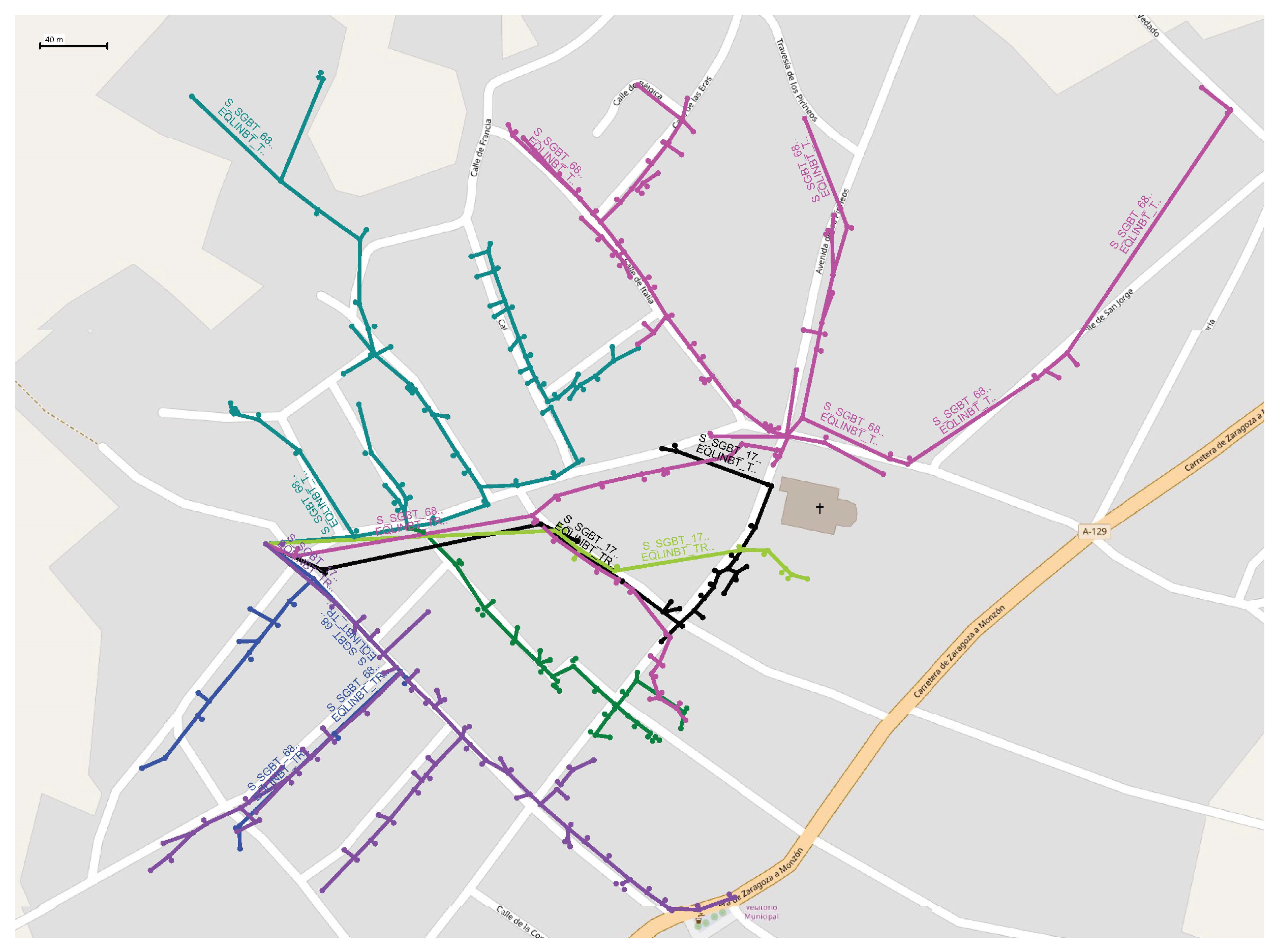
This paper analyses the effect of the massive connection of EVs in low-voltage rural networks by simulating different scenarios in a village in Aragon, Spain. The grid model has been developed in DIgSILENT PowerFactory, and it is based on the data provided by EDISTRIBUCIÓN Redes Digitales, S.L., the main DSO in the region (Figure 1).
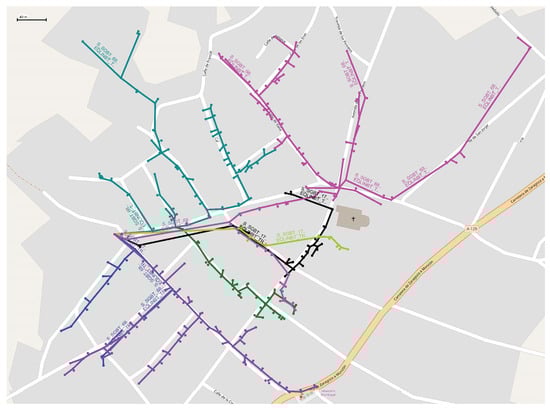
Figure 1.
Analyzed low-voltage power grid.
The results have been obtained using quasi-dynamic simulation. This simulation method is particularly beneficial for medium and long-term planning analyses, where variable demand and generation profiles are established, and the network’s evolution is modeled in various expansion stages. During these phases, multiple load flow simulations are executed with user-defined time intervals, ranging from minutes to hours [51].
The analysis is focused on the effect of the charging process on the network, specifically examining the following:
- Voltage drops;
- Network saturation;
- Unbalanced currents and voltages;
- Increase in network losses.
Various options exist for measuring the imbalance of three-phase networks [30], with the most commonly used being the Unbalance Factor (UF), defined by decomposing the network into its symmetrical components. In this way, considering only positive and negative sequences, UF is typically expressed as:
where G can be either voltages or currents, is the value corresponding to the negative sequence, and is that of the positive sequence.
In the case of four-wire three-phase networks, the most commonly used is the unbalance factor , defined as:
where G0 is the zero-sequence or homopolar component. In the rest of the paper, CUF and CUF0 will refer to Current Unbalance Factors, and VUF and VUF0 will refer to Voltage Unbalance Factors.
The ANSI standard [52] suggests that the voltage unbalance factor (VUF0) values should be kept below 3%, whereas the International Electrotechnical Commission (IEC) [53] and the International Council on Large Electric Systems (CIGRE) [54] related standards establish a limit of 2%, permitting it to reach 3% in networks with a high concentration of single-phase customers to guarantee supply quality.
3.1. Network Description
The modeled network comprises seven circuits connected to the company’s medium-voltage network through a 15 kV/400 V/230 V three-winding transformer. Among these circuits, three are linked to the 400 V output, while the remaining four are connected to the 230 V output of the transformer. The 400 V output is utilized for supplying three-phase loads, as well as single-phase loads with a phase-neutral connection at 230 V. On the other hand, the 230 V output supplies single-phase loads connected between two phases. A network equivalent represents the medium-voltage network, as the study primarily focuses on analyzing the behavior of the low-voltage network downstream of the transformer. Figure 1 shows the analyzed network, where each color represents a different circuit.
The low-voltage network comprises insulated cables with aluminum conductors ranging in sections from 25 mm2 to 150 mm2 across all lines. Distances between nodes vary, as they are based on actual network data, and the spacing between connection points is not uniform. The maximum distance between two nodes is 221 m, found at the end of Circuit 4, while the minimum distance is 5 m. The network comprises 499 terminals interconnected by 509 cables, with a total of 251 loads connected to these circuits. These loads are characterized based on the contracted power at installation nodes and usage factors, which depend on the load type, whether residential, service, or industrial, according to the circuit distribution indicated in Table 1. Industrial and service loads are small workshops, shops and offices in the village. These loads have been considered three-phase loads with delta connection. Domestic loads are typically single-family detached or semi-detached houses with some small blocks of flats. These domestic loads are considered single-phase or three-phase regarding the contracted power. If the contracted power is smaller than 5.5 kW, it has been assumed that this is a single-family house whose connection is single-phase. However, if the contracted power is higher than that value, it has been assumed that there is more than one home, and therefore, it has been assumed that the load is three-phase.

Table 1.
Distribution of the loads in the network circuits.
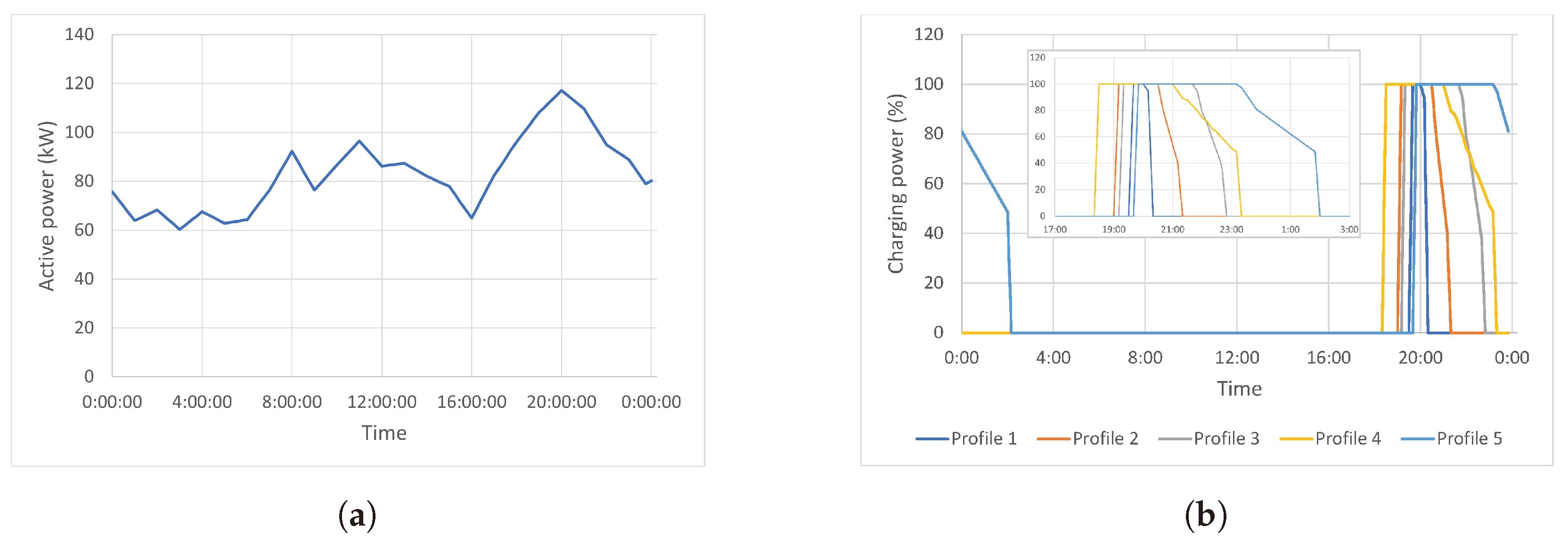
Furthermore, the variation in consumed power has been determined from current measurements at the transformation centre provided by the distribution company. The measurement campaign was carried out over a month, and from these data, a typical week curve was determined for that season (Figure 2a). The figure shows that the power demanded by the loads remains within a range of 50 to 100 kW throughout the day, except for the period between 18:30 and 21:30, coinciding with the typical arrival time at homes in Spain, when demand increases, reaching the highest peak at 20:00.
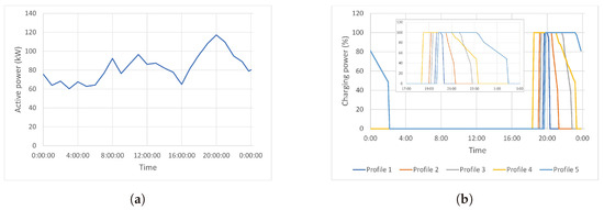
Figure 2.
(a) Power consumed by loads as a function of time of day; (b) charging profile of Electric Vehicles (EVs) at slow charging, p < 3.7 kW with a zoom into the charging period.
3.2. EV Charging Modes
The IEC 61851-1 standard [55] establishes four charging modes for electric vehicles. Modes 1, 2, and 3 all involve charging in alternating current, with the charger on board the vehicle, at power levels ranging from 3.7 kW in the first case, up to 44 kW in Mode 3. Mode 4 considers alternating and direct current charging with power levels reaching 240 kW. However, when integrating electric vehicles to the grid, the ability to control the charging process from electric vehicle supply equipment (EVSE) is more important than power limits. This control can be based on directives from the DSO or signals from voltages and currents measured at the charger connection point. Only Modes 3 and 4 allow for controlled charging through directives or load limitation. Communication between EV and EVSE in Europe follows the ISO 15118 protocol [56] for both Mode 3 and the Combined Charging System (CCS) of Mode 4, as well as wireless charging. Intelligent charging applications calculate personalized charging schedules based on grid conditions, energy requirements, and driver mobility schedules. This ensures each charging session is optimally adjusted to the grid’s capacity and the electric demand generated by simultaneous electric vehicle charging. Finally, it should also be considered that according to [57], the predominant trend for charging in various studied countries globally occurs after 18:00, peaking around 21:00 when users arrive home.
According to the IEA’s Global Electric Vehicle Outlook 2022 [57], it is projected that by 2030, 90% of EV chargers will be privately owned, ranging in power from 3 to 22 kW. This form of charging is expected to remain dominant, particularly for personal vehicles, with 70% of the total energy dedicated to EV charging derived from private chargers. The proportion of private charging stations will largely hinge on whether EV owners reside in individual homes or larger residential complexes. In Spain, the Business Association for the Development and Promotion of Electric Mobility estimates that 85.9% of EV owners have private chargers installed in their homes [58]. However, it is important to note that the average power contracted by Spanish households stands at 4.2 kW, according to the National Commission for Markets and Competition. This figure dropped to 3.9 kW over the past year for households with contracts in the regulated market [59]. Given the high cost associated with the contracted power term, there is a prevailing trend towards reducing the contracted power level. Consequently, it has been assumed in this study that charging will occur at a lower power rating of 3.7 kW. This decision is primarily driven by the desire to mitigate the need for most users to increase their electricity contract’s power term, which would significantly escalate electricity bill expenses. Therefore, the domestic charging stations examined in this study will utilize single-phase chargers with control capabilities (Mode 3), and charging will commence upon the individual’s arrival at home.
3.3. Definition of Scenarios
The network described in Section 3.1 corresponds to the current situation of the grid, which has been called “Scenario 0”. As the work aims to study the effects of the integration of EVs in the grid, the expectations regarding the number of electric vehicles and chargers in the region have been considered to define what has been called “Scenario 1”.
In Spain, on 3 November 2020, the Council of Ministers approved the ‘Estrategia a Largo Plazo para una Economía Española Moderna, Competitiva y Ambientalmente Neutral en 2050’ (ELP 2050), a document that outlines the roadmap to achieve climate neutrality by 2050. The ELP 2050 guides in attaining the proposed objectives specified for each decade in the ‘Plan National Integrado de Energa y Clima’ (PNIEC) [17]. PNIEC aims at achieving electrification (100%) in the road transport sector by 2050 and sets a goal for Spain to deploy 5.5 million electric vehicles (EV) by 2030. According to the 2022 report of the Spanish Association of Automobile and Truck Manufacturers (ANFAC) [60], the Spanish fleet totaled over 30.2 million vehicles, of which 25.6 million were passenger cars, accounting for approximately 84.8%. Extrapolating vehicle registration data from the historical series provided by ANFAC, it can be considered that by 2030, there will be around 32.8 million vehicles, with 27.7 million being passenger cars. According to this proportion, of the 5.5 million electric vehicles projected by the PNIEC for 2030, slightly more than 4.2 million will be passenger cars, representing (15.2%) of the total passenger cars. Using the statistical data from the Spanish National Institute of Statistics (INE), Spain is expected to have around 50.5 million inhabitants in 2030, resulting in a passenger car motorization rate of nearly 550 cars per 1000 inhabitants. Based on an analysis of the town’s characteristics, including its average size and a stable population of 1200 inhabitants, the number of vehicles in the area is expected to mirror the national average. By 2030, it is projected that there will be approximately 660 vehicles, of which 100 are estimated to be electric. These projections rely on assumptions of demographic stability and do not encompass possible changes in transportation patterns or social dynamics. According to INE data, about 26% of the vehicles in the Aragón region are parked on the street. Consequently, only 74% of the vehicles would have access to private charging facilities at their residences. Given that not all cars require daily charging, and according to the experience of the distribution company, which provided the network data, we have assumed that only 75% of the drivers available to charge at home do so regularly, so only 56 vehicles will require daily charging upon returning home.
The charging profiles of electric vehicles have been chosen considering only weekdays for the sake of simplicity. The profiles have been defined considering different charge starting times and charging states. The starting times range between 18:30 and 20:00, as they are the typical arrival times at homes in Spain. Regarding the charging states, five different load profiles have been defined for 65%, 56%, 47%, 39% and 29% of the maximum load when the charge starts. Each vehicle connected to a charging point has been randomly assigned one of these five charging states. Figure 2b shows the used charging profiles.
Once the two base scenarios, Scenario 0 without EVs and Scenario 1 with EVs, are analyzed, three solutions are proposed to mitigate the effects of the penetration of the EVs in the grid. They are defined as Scenarios 2, 3 and 4. Scenario 3 includes a control system for EV charging based on a threshold for the maximum voltage drops allowed in the grid. In Scenario 2, a 4-branch D-FACTS is connected to the grid for current balancing. Finally, Scenario 5 combines both solutions, D-STATCOM and the controlled charging system.
4. Impact of Uncontrolled Charging of Electric Vehicles on the Low Voltage Network
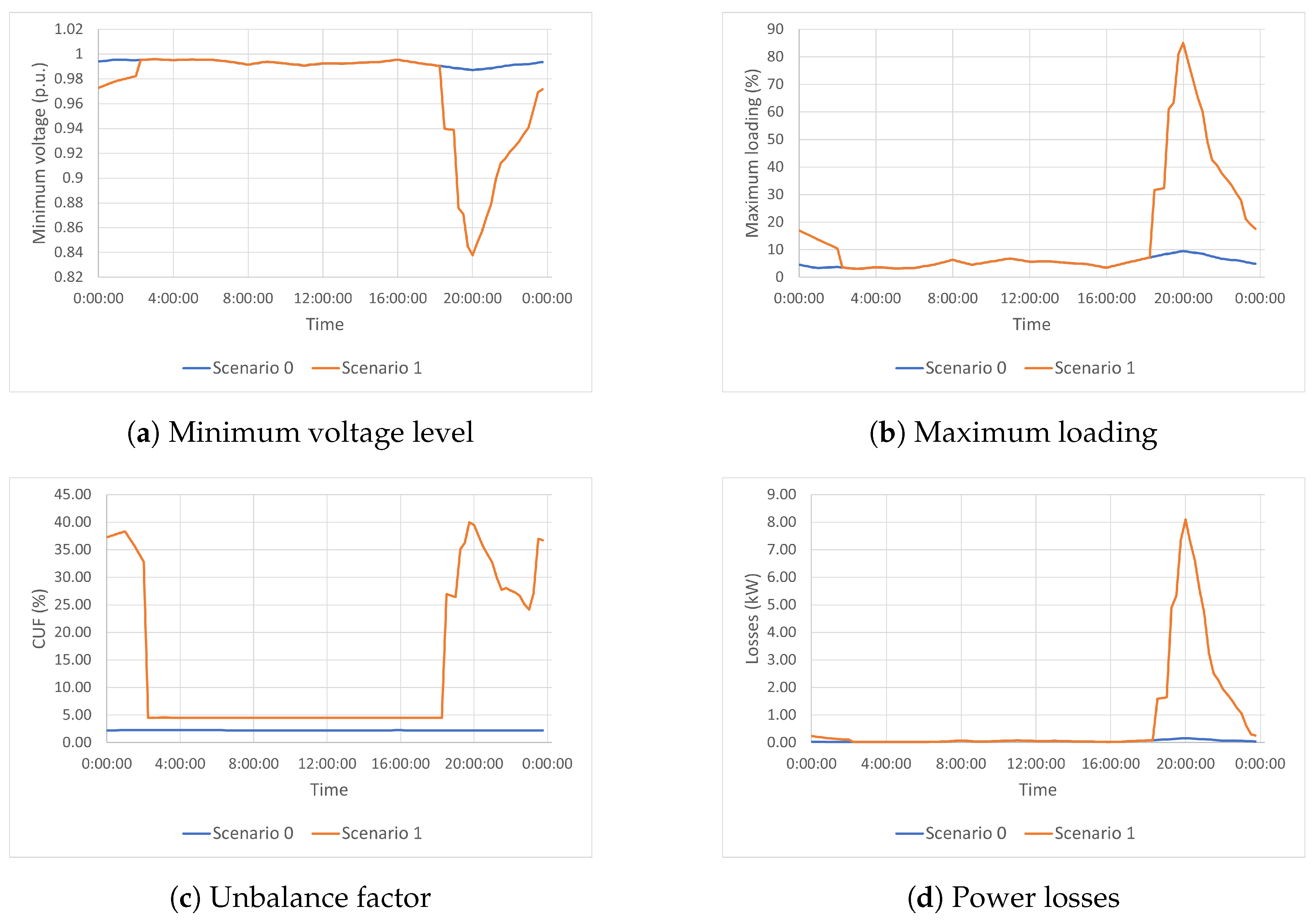
This section examines the simulation results conducted before (Scenario 0) and after (Scenario 1) for the connection of electric vehicles in the analyzed network according to the previously described criteria. In Scenario 0, the distribution network analysis is carried out for the configuration shown in Figure 1 under current grid conditions and with the load profile illustrated in Figure 2a. In Scenario 1, 56 electric vehicles are introduced with slow charging at 3.7 kW using single-phase chargers, randomly distributed throughout the distribution network, and considering the five charging profiles outlined in Figure 2b.
Figure 3 and Table 2 show the typical weekday results. Figure 3a compares the minimum voltage values reached in the analyzed network. As can be seen in Scenario 0, the voltage remains above 0.9 p.u. with a minimum value of 0.98. However, the increase in current due to uncontrolled charging of the EVs causes the voltage to drop, reaching a minimum of 0.84 p.u., below the prescribed lower limit of 0.9 p.u. [61]. Regarding the maximum loading, Figure 3b shows that the network is significantly oversized, with a minimum value in Scenario 0 lesser than 9.5% and a significant increase when introducing EV charging, reaching a maximum of 85.06%, which translates to an increase of 75.56%. As expected, the limiting factor in this network is the voltage at the farthest points from the transformation center, so this will be the parameter to consider when controlling the charging process, as explained in the following sections.

Figure 3.
Comparison of the obtained results during a typical week day for Scenario 0 and Scenario 1.
Table 2.
Comparison of the results before and after the connection of the EVs.
During the charging process of EVs, there is a significant increase in the unbalance factor, as shown in Figure 3c. The first peak is observed at 20:00 when all vehicles are connected and charging at the same time, but after that moment, there is a reduction from 39.97% to 27.73% at 21:30, and a new increase reaching 37.00% when EVs with Profile 4 stop charging. Therefore, for the unbalance factor, it is necessary to consider not only the number of installed chargers per phase, but also the number of active chargers, which is a random number that depends on the users’ habits. Global control of the charging process of the VEs can help avoid this effect as will be showed in the next sections. Figure 3d compares the losses in the low voltage lines that increase in Scenario 1 due to the current increase during the VEs charging process, as expected.
Table 2 summarizes the most relevant results. Using Scenario 0 as a reference, the uncontrolled charging of electric vehicles, corresponding to Scenario 1, causes an increase in the current flowing through the low-voltage lines. The low load rate obtained in Scenario 0 indicates that the line is oversized, allowing for the 75.56% increase obtained in Scenario 1 without overloading. However, this result clearly shows that this situation would lead to network overload with a tighter design. Secondly, the significant increase in current produces two detrimental effects. The first one is a reduction below normal operating limits in voltage at the furthest points from the transformer. The second is a substantial increase in losses in the distribution network itself.
5. Improvements to the Charging Procedures
The results obtained in Section 4 clearly show that the charging of EVs produces a severe impact on the studied low-voltage network. Here, two different options are proposed to minimize these negative effects, expanding the connection capacity of EVs. They are the control of the EVs charging process and the connection of specific power electronic devices to reduce voltage and current unbalance. Subsequently, three more scenarios will be studied:
- Scenario 2: Charging process control addressing the maximum voltage drop.
- Scenario 3: Connection of specific power electronics configurations to reduce voltage and current unbalance.
- Scenario 4: Combined solution from Scenarios 2 and 3.
5.1. Scenario 2: Charging Process Control Attending to the Maximum Voltage Drop
To mitigate the problem of voltage drops caused by EVs charging, a car charging control mechanism is proposed to ensure that the minimum voltage at the grid nodes does not drop below the 0.9 p.u. limit [61], while keeping the line load below 100%. For this purpose, an iterative algorithm is proposed (see Figure 4), which, based on monitoring the grid voltage at critical points, checks if the voltage does not drop below a certain safety threshold (0.92 p.u). If it reaches this value, a parameter J is sent to modify the power setpoint to Mode 3 chargers. The system generates stepwise decreases of 5% in setpoint if the voltage is below the threshold and increments of 5% if the voltage recovers above 0.95 p.u. In Figure 4, t is the waiting time before the next check. Mode 3 chargers receive the parameter J, which is sent to the BMS to adapt the power to where P is the initial value of the power.
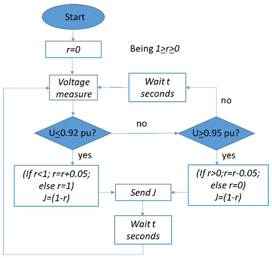
Figure 4.
Voltage Control Flowchart.
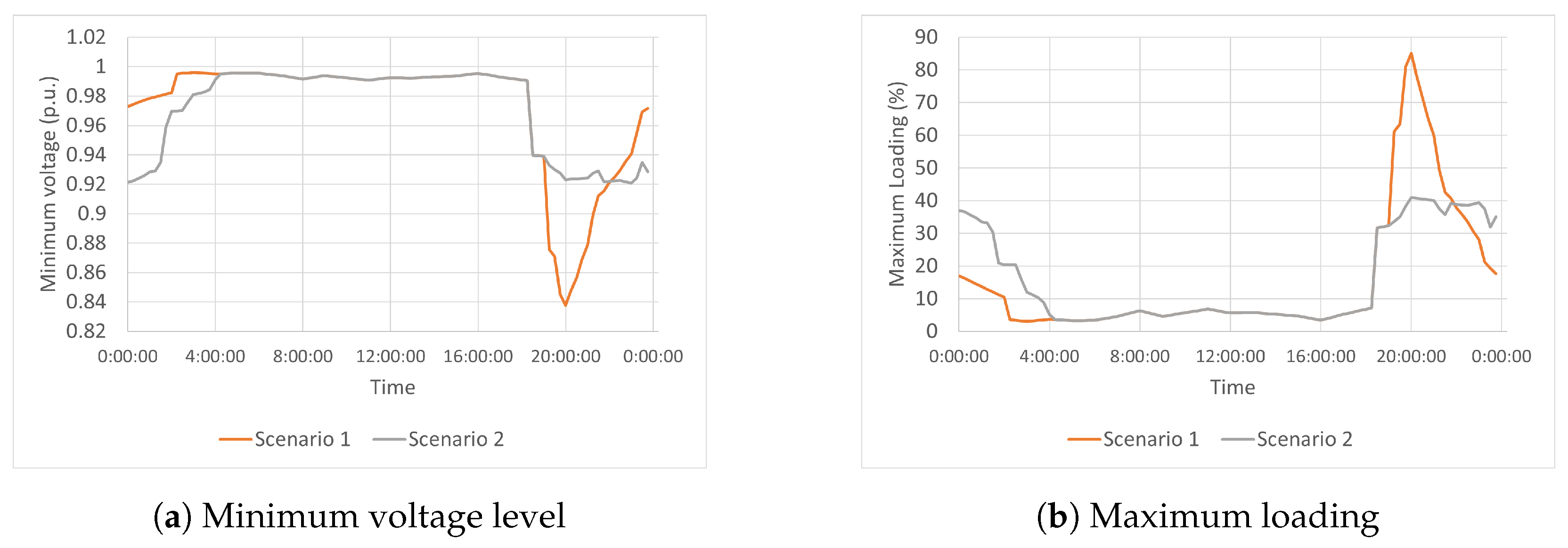
Figure 5 shows the effect of applying the control algorithm to the charging process of the EVs. In Figure 5a, it can be observed that the voltage is consistently maintained within the specified range during the whole charging period. Figure 5b illustrates that network overloading is reduced in 48%, approximately.
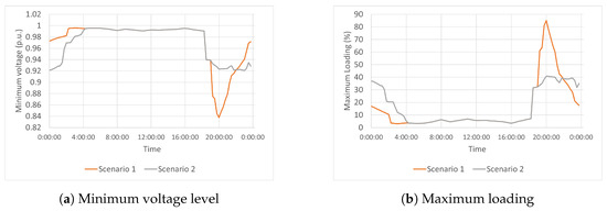
Figure 5.
Comparison of the results of Scenario 2 regarding Scenario 1.
Figure 6 shows the resulting charging profiles of the electric vehicles when the charging control operates (Scenario 2). Reducing the maximum charging power during undervoltage inevitably prolongs the vehicle charging duration but ensures that the voltage remains within the acceptable range. It can be seen how the charging profile of the most discharged vehicle demonstrates a constrained power profile, particularly at the initiation of the charging process when coinciding with other vehicles. As these vehicles progressively complete their charging, the setpoint for the maximum permissible power has been raised. Consequently, the duration of the charging process has been extended by an average of 2 h.
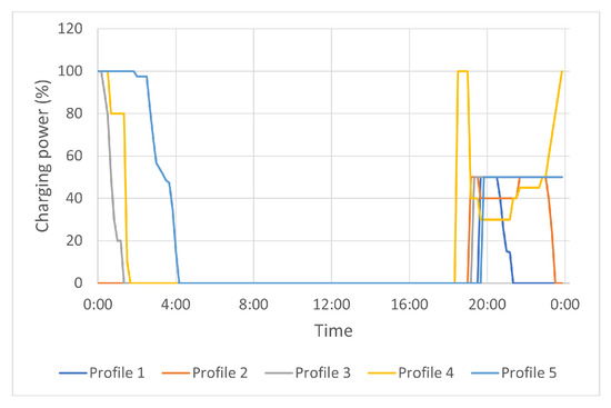
Figure 6.
Charging profiles of Electric Vehicles in Scenario 2.
5.2. Scenario 3: Connection of Specific Power Electronics to Reduce Voltage and Current Unbalance
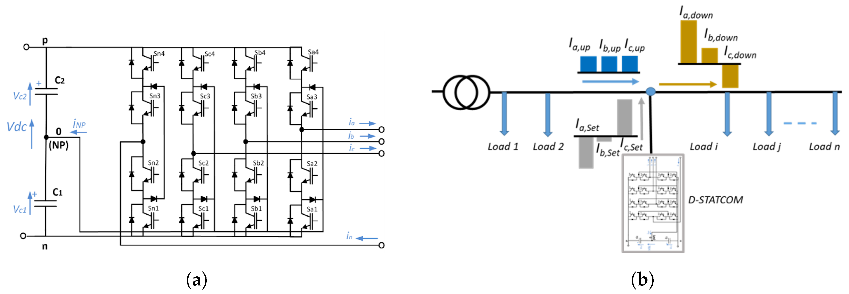
The charging control presented in Section 5.1 can prevent overloads and excessive voltage drops, indirectly mitigating unbalances by reducing current intensity. However, it does not address the issue comprehensively, as it lacks individualized control for current flowing through the phase where each charger is connected. Scenario 3 includes using a three-phase, four-leg D-STATCOM (Figure 7a), connected at low voltage to mitigate the unbalance effect [31]. The fourth leg allows the circulation of current through it, thereby enabling the independent control of currents in each phase without the requirement that the sum of phase currents be zero. However, since it lacks an energy source connected to the DC bus, such as batteries or a generation system, it cannot generate the direct component of active power. Nevertheless, it can extract active power from one phase and inject it into another, thereby maintaining the total sum of active power at zero. This configuration allows the control of the homopolar (zero) and the reverse (negative) components of the current, the direct component of the reactive power, and the active power exchange between phases.

Figure 7.
Description of the D-STATCOM and its operation. (a) 4legs D-STATCOM schematics [31], (b) D-STATCOM connection and current balance.
The goal of this 4 legs D-STATCOM is to have the upstream active power () equal in all three phases and zero reactive power ():
Then, the D-STATCOM must inject the required active power () and reactive power () to compensate for the difference in each phase:
being the reactive power downstream.
Calculating the current setpoint in each phase () is obtained from the apparent power () and the voltage in each phase as follows:
Figure 7b shows the connection to the grid and how the D-STATCOM uses the active power exchange between phases to equilibrate the currents upstream of the connection point.
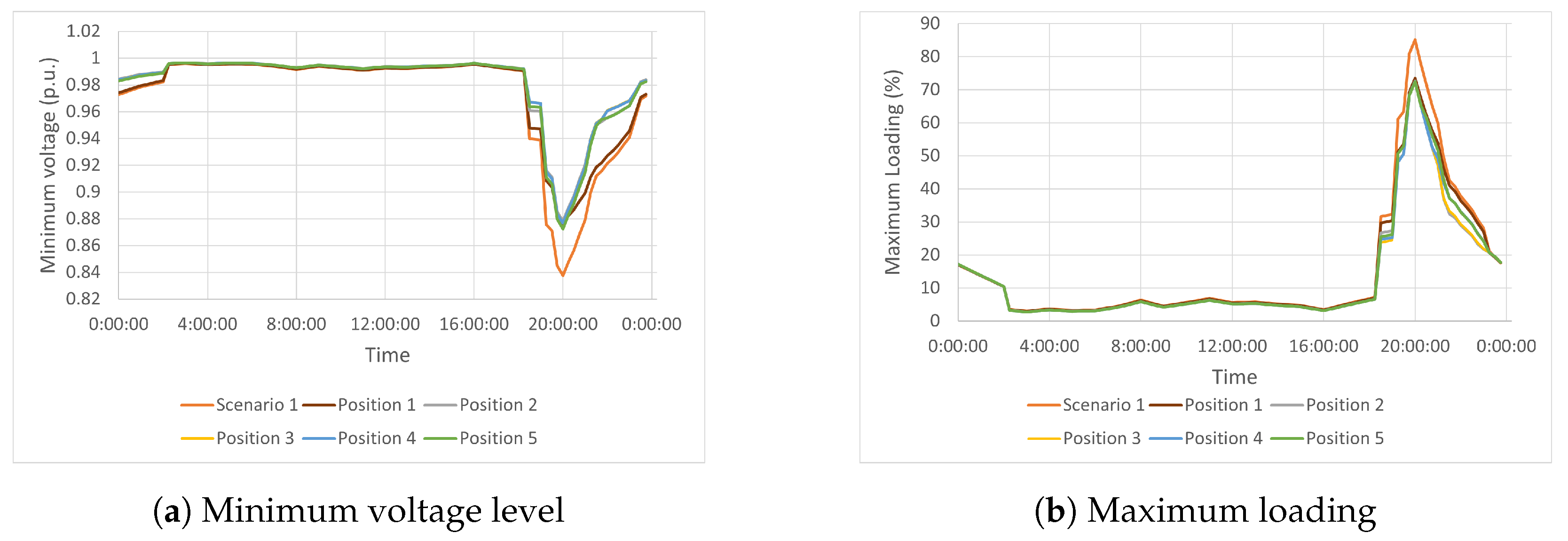
The position of the D-STATCOM should be the most suitable to mitigate the effects of the EV charging process. From the results of Scenario 1, Circuit 3 (in pink in Figure 1), which presents the highest voltage drop, was selected. In this circuit, the impact of a 30 kVA D-STATCOM in 5 different positions was analyzed, with Position 1 being the furthest away from the transformer and Position 5 the closest.
Table 3 and Figure 8 show the results obtained with the D-STATCOM connected at the five selected circuit positions compared to Scenario 1. In all cases, the voltage drop is improved, although it does not reach a value higher than 0.9 p.u., as shown in Figure 8a. The peak load is reduced by approximately 10% in all cases. The optimal outcome was achieved in Position 2, resulting in a significant reduction in maximum neutral current from 152.1 A to 87.5 A, marking a substantial decrease of 58%. Additionally, this position exhibited the most notable improvement in voltage drop, showing an increase of 4%. Furthermore, in Position 2, there was a notable enhancement in the maximum load of the network, which improved from 85.06% to 72.58%.
Table 3.
Comparison of the results depending on the D-STATCOM location.

Figure 8.
Comparison of the results of Scenario 3 with the five different positions for the D-STATCOM regarding Scenario 1.
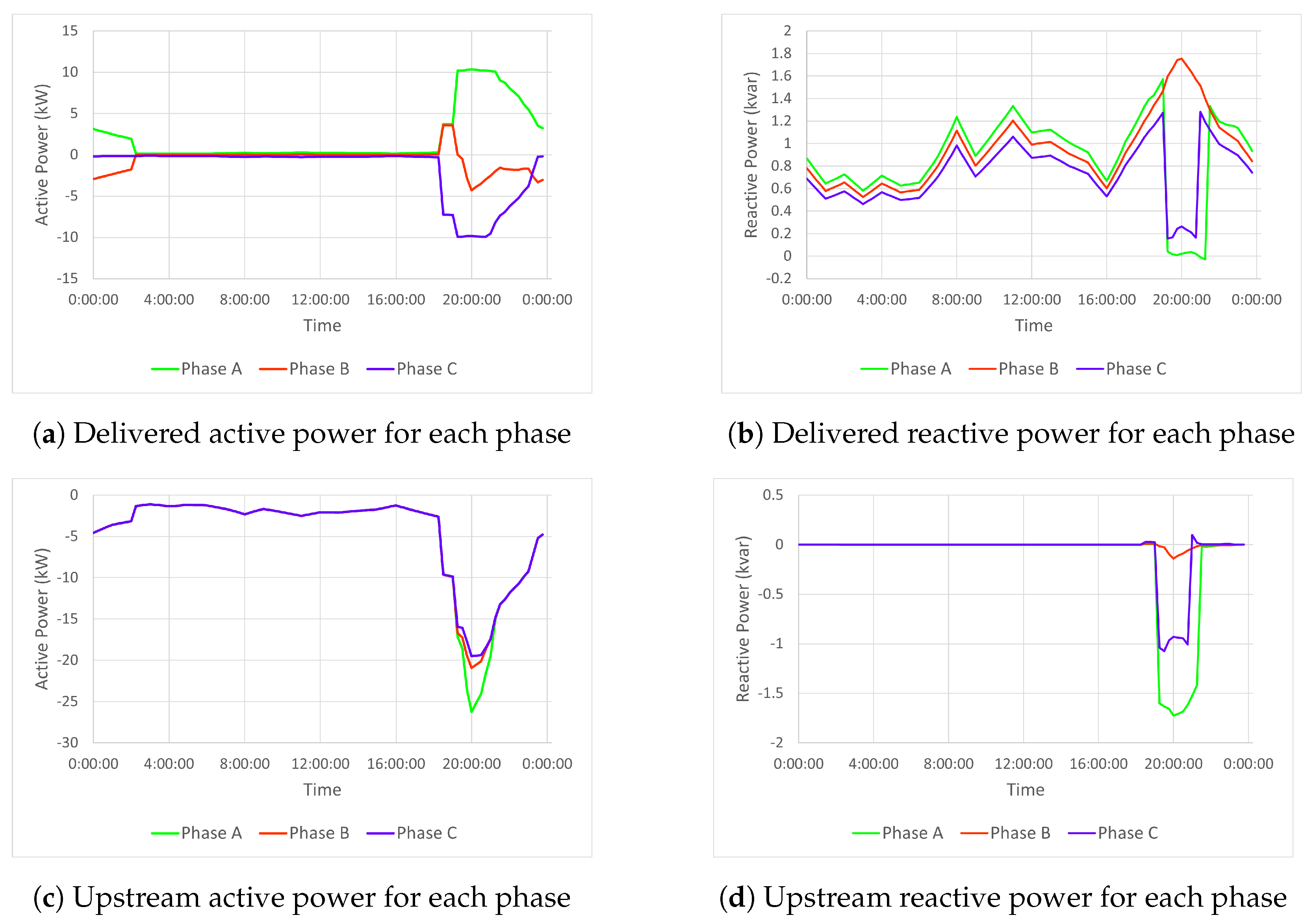
To analyse these results, the active and reactive power contribution of the D-STATCOM in each phase must be considered, as well as the active and reactive power values per phase upstream of the equipment connection point. Figure 9a,b show the active and reactive power exchanged by each phase of the D-STATCOM. The active power exchange is limited to 10 kW in phases A and C during the time interval in which the maximum EV charging current occurs. In this case, the active power exchange has been prioritised; therefore, if the current limit is reached, the active power exchange will be prioritised, and the reactive power exchange will be reduced, as observed between 19:15 and 21:15. This affects the active and reactive power per phase upstream of the D-STATCOM equipment, as shown in Figure 9c,d. When the current limitation is active, the active power through the different phases is different, and the reactive power is different from zero.
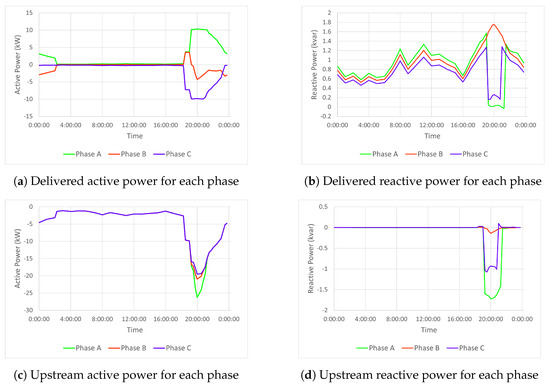
Figure 9.
Delivered active and reactive power (a,b) and Upstream active and reactive power (c,d) in each phase due to the connetion of the 30 kVA D-STATCOM.
When the limit per phase of the D-STATCOM is reached, no matter what position it is connected, the active power balance and the compensation of reactive power in all phases can not be achieved. Figure 9a shows how Phases A and C reach the 10 kW limit, preventing the injection of reactive power during that period, as seen in Figure 9b, particularly in Phases A and C. Figure 9c depicts how this limit impedes the balancing of powers across all three phases, especially in Phase A. Furthermore, during the same period, the reactive power of Phase A and Phase C is not reduced, and in the case of Phase B, it is not completely compensated, as seen in Figure 9d. It is worth mentioning here that the D-STATCOM system performs balancing at one point of the analyzed network, so the currents will continue to be unbalanced downstream of the connection point.
To ascertain whether this solution can address the issues related to the uncontrolled connection and charging of electric vehicles, a series of simulations have been conducted to assess the impact of increasing the nominal power of the D-STATCOM at Position 2.
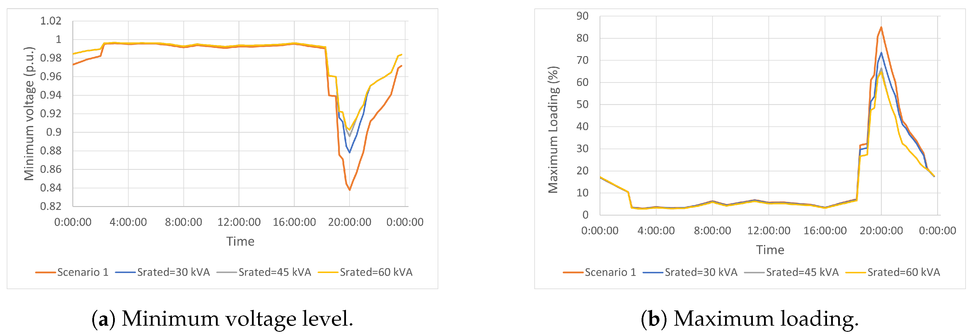
Table 4 and Figure 10 confirm the assumption showing an improvement in the results in terms of voltage, load, and losses when increasing the nominal power of the equipment. It is also reflected that above 60 kVA, there is no improvement, and the results stay the same because the current when the rated power is greater than that value is no longer limited. In this case, the minimum voltage remains at 0.902 p.u., just above the 0.9 p.u. limit given by the standards.
Table 4.
Comparison of the results depending on the D-STATCOM rated power.
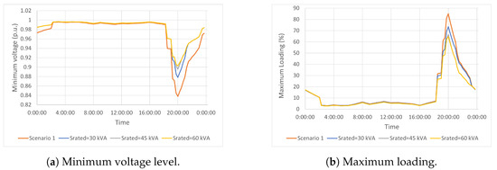
Figure 10.
Comparison of the results of Scenario 3 with different rated power values for the D-STATCOM regarding Scenario 1.
5.3. Scenario 4: Combinations of the Solutions from Scenario 2 and Scenario 3
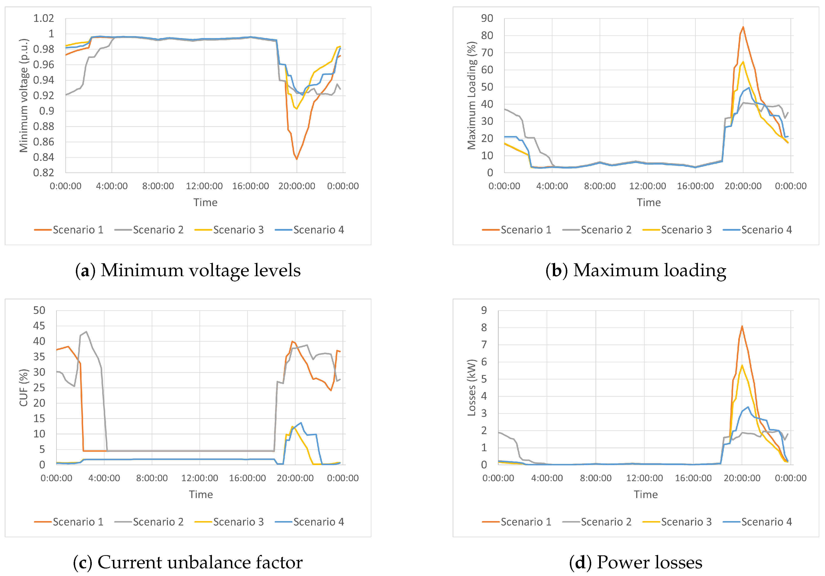
In Scenario 4, the combination of connecting a 30 kVA D-STATCOM unit, explained in Scenario 3, along with the electric vehicle load control, corresponding to Scenario 2, has been analyzed. Table 5 and Table 6 as well as Figure 11 compare the results obtained in the four scenarios with EV. The chosen case for Scenario 3 was that which included a D-STATCOM with a rated power of 60 kVA. Scenarios 2, 3, and 4 manage to limit voltage drop within the desired limit of 0.9 p.u. The main difference is noticeable from 20:00 onwards, when the most significant voltage drop occurs along with the highest increase in maximum load. Scenarios incorporating load control through voltage monitoring yield the best results in this regard. Furthermore, as expected, the best balancing data is obtained in scenarios including the D-STATCOM. It can be observed from Table 5 and Table 6 that voltage control in Scenario 2 limits voltage value but worsens current unbalance. In Scenario 4, the combination of a D-STATCOM with half the power of that considered in Scenario 3, along with load control from Scenario 2, clearly achieves the best overall results. Table 6 shows the improvement of the analyzed indices in percentage. It can be seen that Scenario 4 exhibits the best overall performance. Only Scenario 3 slightly enhances current unbalance results at the cost of doubling the equipment’s power. Finally, it is important to indicate that the voltage imbalance limit of 2% indicated by the regulations is not reached in all the proposed solutions.
Table 5.
Comparison of the results in the analysed Scenarios.
Table 6.
Comparison of the improvement in the evaluated indexes for the analysed Scenarios.

Figure 11.
Comparison of results for the four analysed scenarios.
6. Conclusions
In the coming years, a significant increase in electric vehicles is expected due to the objectives associated with the energy transition. The charging of these electric vehicles from the electrical grid represents a substantial increase in energy demand that can cause saturation problems, undervoltage, and increased losses in the network. There are solutions to address these impacts, but they usually involve significant investments in infrastructure to build new transformation centers, new lines, etc.
In Spain, it is projected that by 2030, 5.5 million EVs will need to be charged from the electrical grid. The majority will be in cities, but a significant percentage will be in small towns whose electrical grids are predominantly weak radial networks and where a significant investment in new infrastructure is not profitable due to the low number of users. This study examines the impact that the charging of electric vehicles will have on a real low-voltage rural network in a town in Spain by that date and explores possible solutions that do not involve the construction of new infrastructure. For this purpose, a preliminary analysis of the projected number of EVs has been conducted to model a future scenario in which the charging of EVs is carried out mainly in households at night and without any control; that is, the charging is carried out when the user connects the vehicle to the network. It is observed that charging may lead to problems with excessive voltage drops and a significant increase in current unbalance, which implies a restriction on the deployment of electric mobility.
Three solutions are proposed to address this issue. Firstly, controlling the vehicle charging by limiting the power based on the voltage drop in the distribution network is suggested. This solution ensures that voltage levels remain within advised limits, with a minimum value of 0.9 p.u., while reducing line losses by 46.7% and decreasing the maximum load by 51.9%. These benefits are achieved by extending the charging time of affected vehicles by two hours to complete the charge of the EVs. However, this method increases the current unbalance by 8.4%.
The second proposed method involves installing a 4-branch D-STATCOM capable of balancing active power upstream to achieve zero current in the neutral while also reducing or eliminating reactive power upstream of its point of connection. With this system, the balance is obtained only in the line that is upstream of the connection point; in the rest of the network, the unbalance is present, but a reduction in the neutral current and a general improvement in the balance is obtained, which makes this solution attractive in case of large imbalances. The optimal location of the equipment is studied to analyze this solution, followed by assessing the required power and concluding that a power of 60 kVA is necessary for the proposed application in this network. This solution reduces current imbalances by around 70% and decreases losses by lowering the maximum line load up to 27%, but it has a smaller reduction in voltage drop than the first solution. However, this method is limited by the equipment’s power as its effects depend on the point of connection and the imbalance in the grid.
The third and final proposed solution combines the previous two methods, using a 30 kVA D-STATCOM. This combination provides the benefits of both previous solutions at a lower cost, halving the power of the D-STATCOM. With this solution, line loading is reduced by 41.6%, while the current balance is improved up to 65.4%, reducing losses by 52% with a minimum voltage of 0.92 p.u.
Encouraging off-peak charging, particularly at night, can be accomplished by implementing higher tariffs during periods of high demand or by incentivizing users to install programmable devices. These measures can significantly contribute to a more equitable distribution of electrical load throughout the day, benefiting both grid management and users regarding energy efficiency and cost reduction. However, this may not be the best solution, as it does not guarantee that the grid voltage is maintained at adequate values. Much more interesting is the promotion of dynamic load control (V1G). This concept will allow EV charging to be adapted to the conditions of the grid where the vehicles are connected and will also improve the penetration of renewable energies, mainly distributed generation in households. The V1G concept will also allow future EV owners to participate by offering flexibility services to the DSO, such as congestion reduction or peak shaving. Finally, the sooner the implementation of dynamic controllable charging starts, the better the results will be, enabling higher penetration of EVs and distributed generation in LV grids.
On the other hand, as has been seen, keeping voltages within the allowed ranges does not prevent the occurrence of significant imbalances. This problem may increase with the installation of distributed generation. In this respect, the DSO can rethink or reinforce the network. However, given the changing load profile of the grid and its variability over time in this new paradigm of EV and DG penetration, it is preferable to have dynamic systems that adapt to this variability, and the proposed DS-STATCOM has been demonstrated as a good solution.
In summary, it is possible to connect the number of electric vehicles expected by 2030 to this network without building new lines or other infrastructure. Still, it is necessary that the charging of these vehicles is carried out in a controlled manner. The two solutions analyzed in this article and, especially, the combination of them allow the voltage values to remain in the considered range, a reduction in losses, and a decrease in the current imbalance index.
Author Contributions
Conceptualization, M.P.C. and J.F.S.-O.; methodology, M.P.C., J.F.S.-O. and J.J.M.; software, M.P.C. and O.G.-I., validation, M.P.C. and O.G.-I.; writing—original draft preparation, J.J.M., O.G.-I. and J.F.S.-O.; writing—review and editing, J.J.M.; supervision, M.P.C. and J.F.S.-O. All authors have read and agreed to the published version of the manuscript.
Funding
Grant TED2021-131397B-I00: “Transición ecológica en áreas rurales” funded by MCIN/AEI/10.13039/501100011033 and by the European Union NextGenerationEU/PRTR. Grant of the Innovation and Energy Sustainability Endesa Chair at the University of Zaragoza.
Institutional Review Board Statement
Not applicable.
Informed Consent Statement
Not applicable.
Data Availability Statement
The datasets presented in this article are not readily available because they are subject subject to a confidentiality agreement with the owner company.
Acknowledgments
The authors of this work would like to thank the Innovation and Energy Sustainability Endesa Chair at the University of Zaragoza for providing the grid data.
Conflicts of Interest
The authors declare no conflicts of interest.
References
- Ritchie, H. Cars, Planes, Trains: Where do CO2 Emissions from Transport Come From? Our World in Data 2020. Available online: https://ourworldindata.org/co2-emissions-from-transport (accessed on 26 October 2023).
- Noel, L.; de Rubens, G.Z.; Kester, J.; Sovacool, B.K. Beyond emissions and economics: Rethinking the co-benefits of electric vehicles (EVs) and vehicle-to-grid (V2G). Transp. Policy 2018, 71, 130–137. [Google Scholar] [CrossRef]
- Vega-Perkins, J.; Newell, J.P.; Keoleian, G. Mapping electric vehicle impacts: Greenhouse gas emissions, fuel costs, and energy justice in the United States. Environ. Res. Lett. 2023, 18, 014027. [Google Scholar] [CrossRef]
- Woody, M.; Vaishnav, P.; Keoleian, G.A.; Kleine, R.D.; Kim, H.C.; Anderson, J.E.; Wallington, T.J. The role of pickup truck electrification in the decarbonization of light-duty vehicles. Environ. Res. Lett. 2022, 17, 034031. [Google Scholar] [CrossRef]
- BOE. Ley 7/2021, de 20 de Mayo, de Cambio Climático y Transición Energética. 2021. Available online: https://www.boe.es/eli/es/l/2021/05/20/7/con (accessed on 1 March 2024).
- Guzek, M.; Jackowski, J.; Jurecki, R.S.; Szumska, E.M.; Zdanowicz, P.; Żmuda, M. Electric Vehicles—An Overview of Current Issues—Part 1—Environmental Impact, Source of Energy, Recycling, and Second Life of Battery. Energies 2024, 17, 249. [Google Scholar] [CrossRef]
- Venegas, F.G.; Petit, M.; Perez, Y. Active integration of electric vehicles into distribution grids: Barriers and frameworks for flexibility services. Renew. Sustain. Energy Rev. 2021, 145, 111060. [Google Scholar] [CrossRef]
- Draz, M.; Vob, M.; Freund, D.; Albayrak, S. The impact of electric vehicles on low voltage grids: A case study of Berlin. In Proceedings of the 20th Power Systems Computation Conference, PSCC 2018, Dublin, Ireland, 11–15 June 2018. [Google Scholar] [CrossRef]
- Purvins, A.; Covrig, C.F.; Lempidis, G. Electric vehicle charging system model for accurate electricity system planning. IET Gener. Transm. Distrib. 2018, 12, 4053–4059. [Google Scholar] [CrossRef]
- Cardenas, A.; Guzman, C.; Martinez, W. EV Overnight Charging Strategy in Residential Sector: Case of Winter Season in Quebec. Vehicles 2021, 3, 557–577. [Google Scholar] [CrossRef]
- Richardson, P.; Flynn, D.; Keane, A. Optimal charging of electric vehicles in low-voltage distribution systems. IEEE Trans. Power Syst. 2012, 27, 268–279. [Google Scholar] [CrossRef]
- Nadolny, A.; Cheng, C.; Lu, B.; Blakers, A.; Stocks, M. Fully electrified land transport in 100networks dominated by variable generation. Renew. Energy 2022, 182, 562–577. [Google Scholar] [CrossRef]
- Dillman, K.J.; Fazeli, R.; Shafiei, E.; Örvar, G.; Jónsson, J.; Haraldsson, H.V.; Davíðsdóttir, B. Spatiotemporal analysis of the impact of electric vehicle integration on Reykjavik’s electrical system at the city and distribution system level. Util. Policy 2021, 68, 101145. [Google Scholar] [CrossRef]
- Straub, F.; Maier, O.; Göhlich, D.; Zou, Y. Forecasting the spatial and temporal charging demand of fully electrified urban private car transportation based on large-scale traffic simulation. Green Energy Intell. Transp. 2023, 2, 100039. [Google Scholar] [CrossRef]
- Arendarski, B.; Lombardi, P.; Mencke, N.; Komarnicki, P.; Parol, M.; Polecki, M.; Rokicki, L.; Poplawska, M.; Luto, M.; Piotrowski, M.; et al. Concept of rural intelligent grid interactive planning methodology. In Proceedings of the Proceedings—EPNet 2016, Electric Power Networks, Szklarska Poreba, Poland, 19–21 September 2016. [Google Scholar] [CrossRef]
- Girbau-Llistuella, F.; Díaz-González, F.; Sumper, A.; Gallart-Fernández, R.; Heredero-Peris, D. Smart Grid Architecture for Rural Distribution Networks: Application to a Spanish Pilot Network. Energies 2018, 11, 844. [Google Scholar] [CrossRef]
- Ministerio para la Transición Ecológica y el Reto Demográfico. Borrador de actualización del Plan Nacional Integrado de Energía y Clima 2023–2030. 2023. Available online: https://www.miteco.gob.es/content/dam/miteco/es/energia/files-1/_layouts/15/Borrador%20para%20la%20actualizaciÃşn%20del%20PNIEC%202023-2030-64347.pdf (accessed on 26 January 2024).
- Dall-Orsoletta, A.; Ferreira, P.; Dranka, G.G. Low-carbon technologies and just energy transition: Prospects for electric vehicles. Energy Convers. Manag. X 2022, 16, 100271. [Google Scholar] [CrossRef]
- Jones, A.; Begley, J.; Berkeley, N.; Jarvis, D.; Bos, E. Electric vehicles and rural business: Findings from the Warwickshire rural electric vehicle trial. J. Rural Stud. 2020, 79, 395–408. [Google Scholar] [CrossRef]
- Yu, H.; Lei, X.; Niu, S.; Jian, L. Hybrid AC/DC Microgrid Reconstruction in Rural Low-Voltage Distribution Grids to Enhance Electric Vehicle Penetration. In Proceedings of the Hybrid AC/DC Microgrid Reconstruction in Rural Low-Voltage Distribution Grids to Enhance Electric Vehicle Penetration, Hefei, China, 12–14 May 2023; pp. 3744–3749. [Google Scholar] [CrossRef]
- Pannala, S.; Khan, A.; Schulz, N.; Srivastava, A.; Sharma, A.; Srivastava, S.C. Cooperative Framework For Mitigation of Voltage Limit Violations in a Rural Distribution System with Electric Vehicles Fleet. In Proceedings of the Cooperative Framework For Mitigation of Voltage Limit Violations in a Rural Distribution System with Electric Vehicles Fleet, New Delhi, India, 17–19 December 2022; pp. 332–337. [Google Scholar] [CrossRef]
- Badiei, Y.; do Prado, J.C. Advancing Rural Electrification through Community-Based EV Charging Stations: Opportunities and Challenges. In Proceedings of the Advancing Rural Electrification through Community-Based EV Charging Stations: Opportunities and Challenges, Cleveland, OH, USA, 25–28 April 2023; pp. 69–73. [Google Scholar] [CrossRef]
- Xu, J.; Wang, H.; Zhang, W.; Wang, T.; Wu, C. Prediction of Electric Vehicle Charging Demand in Rural Areas Based on Driving Track Data. In Proceedings of the Prediction of Electric Vehicle Charging Demand in Rural Areas Based on Driving Track Data, Changchun, China, 24–26 February 2023; pp. 292–296. [Google Scholar] [CrossRef]
- Gschwendtner, C.; Knoeri, C.; Stephan, A. Mind the goal: Trade-offs between flexibility goals for controlled electric vehicle charging strategies. iScience 2023, 26, 105937. [Google Scholar] [CrossRef] [PubMed]
- Goolsby, R.T. Electric Vehicle Charging and Rural Distribution Systems. In Proceedings of the Electric Vehicle Charging and Rural Distribution Systems, Savannah, GA, USA, 27–29 April 2021; pp. 1–5. [Google Scholar] [CrossRef]
- Hartvigsson, E.; Taljegard, M.; Odenberger, M.; Chen, P. A large-scale high-resolution geographic analysis of impacts of electric vehicle charging on low-voltage grids. Energy 2022, 261, 125180. [Google Scholar] [CrossRef]
- Nacmanson, W.J.; Zhu, J.; Ochoa, L.F. Assessing the unmanaged EV hosting capacity of Australian rural and urban distribution networks. In Proceedings of the CIRED Porto Workshop 2022: E-Mobility and Power Distribution Systems, Porto, Portugal, 2–3 June 2022; Volume 2022, pp. 681–685. [Google Scholar] [CrossRef]
- Kurth, M.; Meyer, M.; Vertgewall, C.M.; Lutat, P.; Jung, B.; Ulbig, A.; Peikenkamp, M.; Lorenz, M.; Pletzer, T. Investigating the impact of electric vehicle charging and photovoltaic systems on a rural and a suburban low-voltage grid. In Proceedings of the CIRED Porto Workshop 2022: E-Mobility and Power Distribution Systems, Porto, Portugal, 2–3 June 2022; Volume 2022, pp. 553–557. [Google Scholar] [CrossRef]
- Ghosh, A.; Ledwich, G. Power Quality Enhancement using Custom Power Devices; Springer: New York, NY, USA, 2002. [Google Scholar]
- Islam, M.R.; Lu, H.; Hossain, M.; Li, L. Mitigating unbalance using distributed network reconfiguration techniques in distributed power generation grids with services for electric vehicles: A review. J. Clean. Prod. 2019, 239, 117932. [Google Scholar] [CrossRef]
- Ballestín-Fuertes, J.; Sanz-Osorio, J.F.; Muñoz-Cruzado-Alba, J.; Puyal, E.L.; Leiva, J.; Rivero, J.R. Four-Legs D-STATCOM for Current Balancing in Low-Voltage Distribution Grids. IEEE Access 2022, 10, 779–788. [Google Scholar] [CrossRef]
- Gruzs, T. A survey of neutral currents in three-phase computer power systems. IEEE Trans. Ind. Appl. 1990, 26, 719–725. [Google Scholar] [CrossRef]
- Song, Q.; Yin, Z.; Xue, J.; Zhou, L. Zero-sequence harmonics current minimization using zero-blocking reactor and zig-zag transformer. In Proceedings of the 3rd International Conference on Electric Utility Deregulation and Restructuring Power Technologies, Nanjing, China, 6–9 April 2008; pp. 1758–1764. [Google Scholar]
- Ciontea, C.I.; Iov, F. A Study of Load Imbalance Influence on Power Quality Assessment for Distribution Networks. Electricity 2021, 2, 77–90. [Google Scholar] [CrossRef]
- IEEE Power and Energy Society. IEEE Recommended Practice for Monitoring Electric Power Quality; Technical Report 1159; IEEE: Piscataway, NJ, USA, 2019. [Google Scholar]
- Kim, S.P.; Song, S.G.; Park, S.J.; Kang, F.S. Imbalance Compensation of the Grid Current Using Effective and Reactive Power for Split DC-Link Capacitor 3-Leg Inverter. IEEE Access 2021, 9, 81189–81201. [Google Scholar] [CrossRef]
- Deleanu, S.; Iordache, M.; Stanculescu, M.; Niculae, D. The Induction Machine Operating from a Voltage Supply, Unbalanced and Polluted with Harmonics: A Practical Approach. In Proceedings of the 2019 15th International Conference on Engineering of Modern Electric Systems (EMES), Oradea, Romania, 13–14 June 2019; pp. 181–184. [Google Scholar] [CrossRef]
- Apsley, J.M. Derating of Multiphase Induction Machines Due to Supply Imbalance. IEEE Trans. Ind. Appl. 2010, 46, 798–805. [Google Scholar] [CrossRef]
- Chen, T.H.; Yang, C.H.; Hsieh, T.Y. Case Studies of the Impact of Voltage Imbalance on Power Distribution Systems and Equipment. In Proceedings of the Case Studies of the Impact of Voltage Imbalance on Power Distribution Systems and Equipment, Hangzhou, China, 20–22 May 2009. [Google Scholar]
- Alam, M.J.E.; Muttaqi, K.M.; Sutanto, D. Alleviation of Neutral-to-Ground Potential Rise Under Unbalanced Allocation of Rooftop PV Using Distributed Energy Storage. IEEE Trans. Sustain. Energy 2015, 6, 889–898. [Google Scholar] [CrossRef]
- Abbasi, A.R. Investigation of Simultaneous Effect of Demand Response and Load Uncertainty on Distribution Feeder Reconfiguration. IET Gener. Transm. Distrib. 2020, 14, 1438–1449. [Google Scholar] [CrossRef]
- Lotfi, H.; Ghazi, R.; Naghibi-Sistani, M. Multi-objective dynamic distribution feeder reconfiguration along with capacitor allocation using a new hybrid evolutionary algorithm. Energy Syst. 2020, 11, 779–809. [Google Scholar] [CrossRef]
- Montoya Giraldo, O.; Alarcon-Villamil, J.; Full Professor, J. Operating Cost Reduction in Distribution Networks Based on the Optimal Phase-Swapping Including the Costs of the Working Groups and Energy Losses. Energies 2021, 14, 4535. [Google Scholar] [CrossRef]
- Cortés-Caicedo, B.; Avellaneda-Gómez, L.S.; Montoya, O.D.; Alvarado-Barrios, L.; Álvarez Arroyo, C. An Improved Crow Search Algorithm Applied to the Phase Swapping Problem in Asymmetric Distribution Systems. Symmetry 2021, 13, 1329. [Google Scholar] [CrossRef]
- Nikum, K.; Wagh, A.; Saxena, R.; Singh, A. Power Quality Problems in Large Commercial Load and their Mitigation: A Case Study. In Proceedings of the 2019 IEEE 1st International Conference on Energy, Systems and Information Processing (ICESIP), Chennai, India, 4–6 July 2019; pp. 1–5. [Google Scholar] [CrossRef]
- Dai, C.; Sun, Y. Investigation of the Imbalance Current Compensation for Transformers Used in Electric Railways. In Proceedings of the 2010 Asia-Pacific Power and Energy Engineering Conference, Chengdu, China, 28–31 March 2010; pp. 1–4. [Google Scholar] [CrossRef]
- Jayaprakash, P.; Singh, B.; Kothari, D.P. Three-Phase 4-Wire DSTATCOM Based on H-Bridge VSC with a Star/Hexagon Transformer for Power Quality Improvement. In Proceedings of the 2008 IEEE Region 10 and the Third International Conference on Industrial and Information Systems, Kharagpur, India, 8–10 December 2008; pp. 1–6. [Google Scholar] [CrossRef]
- Li, D.; Wang, T.; Pan, W.; Ding, X.; Gong, J. A comprehensive review of improving power quality using active power filters. Electr. Power Syst. Res. 2021, 199, 107389. [Google Scholar] [CrossRef]
- Teke, A.; Saribulut, L.; Meral, M.; Tümay, M. Active power filter: Review of converter topologies and control strategies. Gazi Univ. J. Sci. 2011, 24, 283–289. [Google Scholar]
- Chen, D.; Xie, S. Review of the control strategies applied to active power filters. In Proceedings of the 2004 IEEE International Conference on Electric Utility Deregulation, Restructuring and Power Technologies, Hong Kong, China, 5–8 April 2004; Volume 2, pp. 666–670. [Google Scholar] [CrossRef]
- Das, H.; Rahman, M.; Li, S.; Tan, C. Electric vehicles standards, charging infrastructure, and impact on grid integration: A technological review. Renew. Sustain. Energy Rev. 2020, 120, 109618. [Google Scholar] [CrossRef]
- American National Standards Institute. Standard ANSI C84.1-2011; Electric Power Systems and EquipmentVoltage Ratings (60 Hertz). National Electrical Manufacturers Association: Rosslyn, VA, USA, 2011.
- International Electrothecnical Comission. Electromagnetic Compatibility (EMC)—Part 3–6: Limits—Assessment of Emission Limits for the Connection of Distorting Installations to MV, HV and EHV Power Systems; Technical Report IEC TR 61000-3-6; IEC: London, UK, 2008. [Google Scholar]
- CIGRE WG C4.07. CIGRE Technical Brochure 261, Power Quality Indices and Objectives; Technical Report; CIGRE: Paris, France, 2004; Available online: https://www.e-cigre.org/publications/detail/261-power-quality-indices-and-objectives.html (accessed on 26 January 2024).
- IEC61851-1:2017; Electric Vehicle Conductive Charging System—Part 1: General Requirements. IEC: Geneva, Switzerland, 2017.
- ISO/IEC 15118-2:2014; Road Vehicles Vehicle-to-Grid Communication Interface Part 2: Network and Application Protocol Requirements. ISO: London, UK, 2014.
- IEA, Paris. Global EV Outlook 2020. 2020. Available online: https://www.iea.org/reports/global-ev-outlook-2020 (accessed on 26 January 2024).
- Asociación Empresarial Para el Desarrollo de la Movilidad Eléctrica, AEDIVE. Anuario 2022–2023 de la Movilidad eléCtrica. 2023. Available online: https://aedive.es/wp-content/uploads/2023/05/Anuario-AEDIVE.pdf (accessed on 10 March 2024).
- Comisión Nacional de los Mercados y ls Competencia, CNMC. Estadísticas Panel de Hogares. 2024. Available online: https://data.cnmc.es/panel-de-hogares/conjuntos-de-datos/estadisticas-panel-de-hogares (accessed on 10 March 2024).
- Asociación Española de Fabricantes de Automóviles y Camiones. ANFAC 2022 Informe Anual. 2022. Available online: https://anfac.com/publicaciones/informe-anual-2022/ (accessed on 12 July 2023).
- Standard EN 50160; Voltage Characteristics of Electricity Supplied by Public Distribution Systems. CENELEC: Brussels, Belgium, 2014.


Disclaimer/Publisher’s Note: The statements, opinions and data contained in all publications are solely those of the individual author(s) and contributor(s) and not of MDPI and/or the editor(s). MDPI and/or the editor(s) disclaim responsibility for any injury to people or property resulting from any ideas, methods, instructions or products referred to in the content. |
© 2024 by the authors. Licensee MDPI, Basel, Switzerland. This article is an open access article distributed under the terms and conditions of the Creative Commons Attribution (CC BY) license (https://creativecommons.org/licenses/by/4.0/).