Article

An Investigation into the Lateral Bearing Performance of a Single Pile Embedded at a Three-Dimensional Asymmetric Local Scour Site Using the Modified Strain Wedge Model

1
School of Civil Engineering and Architecture, Henan University of Science and Technology, Luoyang 471023, China
2
Engineering Technology Research Center of Safety and Protection of Buildings of Henan Province, Luoyang 471023, China
*
Author to whom correspondence should be addressed.
Appl. Sci. 2024, 14(7), 3056; https://doi.org/10.3390/app14073056
Submission received: 1 March 2024 / Revised: 25 March 2024 / Accepted: 3 April 2024 / Published: 5 April 2024

Abstract

:
The scouring effect is widely acknowledged as a primary contributor to the weakening in the bearing performance of offshore piles; it often results in asymmetric scour patterns around the pile. To meticulously examine the impact of three-dimensional asymmetric local scour on the lateral bearing performance of a single pile, the Boussinesq solution is employed to determine the effective stress within the soil encompassing the pile, considering the presence of a three-dimensional asymmetric local scour hole. Utilizing the strain wedge model, the calculation method for the lateral bearing performance of a single pile under the condition of three-dimensional asymmetric local scour is established. The validity of this approach is established, and parameter analysis unveils the effect of varying sizes of three-dimensional asymmetric scour holes on the mechanical properties and displacement performance of a single pile. The analysis reveals that, as scouring dimensions around the pile escalate, the impact of scouring on single-pile lateral displacement and internal forces intensifies, leading to a decrease in the lateral bearing performance of a single pile. At a constant scour depth, the bottom area of the upstream scour hole significantly influences the displacement performance of a single pile. When the bottom length Swb1 of the upstream scour hole grows by 1 time, 4 times, and 8 times, the lateral displacement of a single pile at a buried depth of 6 m is augmented by approximately 0.41%, 1.65%, and 2.06%, respectively. The simplified model obtained via the modified strain wedge model and Boussinesq solution can provide a theoretical basis for the preliminary design of a single pile under asymmetric scour hole conditions.

1. Introduction

In recent years, there has been significant research focused on renewable and clean wind energy as a more effective solution to addressing resource limitations and mitigating climate change. To harness more stable and potent wind resources, there has been a continuous expansion in the performance of offshore structures [1]. In terms of design, manufacturing, and installation, single-pile foundations are the most prevalent and cost-effective choice. In fact, approximately 80% of offshore wind farms in Europe opt for this basic form of foundation [2,3]. Under prolonged exposure to water flow, the presence of a single pile can alter the initial flow field and the dynamics of water flow, leading to local scour. This phenomenon causes the erosion and degradation of the surrounding soil near the pile foundation in offshore wind turbines and other engineering projects. As a result, the lateral bearing performance and stiffness of the pile foundation are significantly affected, posing a serious risk to the stability and safety of the pile foundation and its supporting structure [4]. Therefore, it is necessary to study the influence of scouring on a single pile.
Scholars both domestically and internationally have made noteworthy advancements in investigating erosion-related concerns pertaining to pile foundations, aiming to unveil its impact on the lateral bearing performance of a single pile. Kishore et al. [5] conducted tests on model piles, both with and without scour, to unveil the impact of scouring on the design of laterally loaded piles. Li et al. [6] calibrated the numerical model for a single pile in marine soft soil using field test data without scour and established the correlation between scour dimensions and the ultimate lateral bearing performance of a single pile. Lin et al. [7] revealed the impact of scour dimensions on the bearing performance and displacement behavior of a single pile using the p–y curve method. Through the improved p–y curve method based on Mindlin’s solution, Zhang et al. [8] revealed the influence of the soil stress history and three-dimensional scour geometry on the lateral mechanical properties of a single pile in soft clay. Utilizing a tailored strain wedge method for scour holes, Yang et al. [9] disclosed how scour hole sizes affect the lateral load response of a single pile in sand. Based on the established earthquake–wind–wave–vehicle–bridge (EWWVB) dynamic coupling system, Zhu et al. [10] computed the load–displacement relationship of a pile foundation under different scour degrees using the p–y curve method. In current pile design practices, the local scour effect is typically addressed by removing the sediment layer within the local scour depth range when analyzing the lateral response of the pile. However, the contribution of the sediments surrounding the pile is often disregarded in this process [11,12]. If the soil layer is completely scoured to the scour depth, the pile’s side resistance will be significantly reduced compared to considering the geometry of the scour hole. As a result, there will be a substantial increase in deflection and the maximum bending moment at the top of the pile, which can make the design overly conservative. To facilitate numerical analysis, crater geometry is usually idealized as an inverted truncated cone [7,13]. However, the physical model test clearly shows that the scour hole is asymmetric in reality [14]. For the pile foundation in the asymmetric scour hole, the soil around the pile is eroded to varying degrees, resulting in unequal lateral forces generated via the self-weight of the overlying soil on both sides of the pile foundation along the flow direction, resulting in the pile foundation in a dangerous state. Therefore, it is necessary to study the influence of asymmetric scour holes on the bearing characteristics of horizontally loaded piles.
Through an array of centrifugal model tests on single model piles in saturated sand, Zhu et al. [15] revealed the mechanical characteristics of slender piles under a lateral monotonic load and a cyclic load, and they deduced the static and cyclic p–y curves of a pile. Through the centrifugal test, Chortis et al. [16] revealed the influence of the type and shape of the scour hole on the p–y curve of the rigid pile. Through addressing the Boussinesq point load arising from scour unloading, Zhang et al. [17] developed the p–y analysis method under asymmetric scour conditions, developing a simplified method for calculating lateral loads on small-diameter flexible piles. By adapting the Matlock p–y curve and incorporating the Boussinesq solution, Zhang et al. [18] introduced the concept of average reduced stress to formulate a comprehensive analytical solution for laterally loaded piles in soft clay. The p–y curve method mentioned above is a relatively common analysis method at home and abroad. However, the p–y curve method should be based on the test results, and the p–y curve calculation method suitable for the test site or similar test site should be obtained via inversion and curve fitting. Therefore, the p–y curve method depends on tests and experience.
To accurately evaluate the impact of scouring on the lateral bearing performance of a single pile, further investigation is needed utilizing the achievements from the theory of lateral loaded pile analysis. Introducing the Duncan–Chang model and Mohr–Coulomb model, Xu et al. [19] enhanced the strain wedge and conducted nonlinear analysis of a laterally loaded pile in sand. Leveraging the strain wedge model, Xu et al. [20] incorporated the state-dependent plasticity model to compute the stress–strain relationship of sand within the wedge. Based on a strain wedge, Abbasi et al. [21] proposed a versatile state-dependent constitutive model to promote its predictive performance across different scenarios. Peng et al. [22] presented a modification of the strain wedge model in sloped pile foundations. Utilizing a modified three-dimensional cone-shaped strain wedge model, Zhang et al. [23] proposed a novel technique for calculating the ultimate shaft resistance of piles in sand. Using the modified strain wedge model, Xu et al. [24] derived the p–y criterion for rock-socketed piles while considering Hoek–Brown failure criterion. Wang et al. [25] proposed the conical strain wedge (CSW) model to conduct the nonlinear analysis of a single pile subjected to lateral loading within layered soil. Wang et al. [26] proposed a scour failure wedge (SFW) model to simulate the interaction between laterally loaded piles and sand with local scour. Zhang et al. [27] established an approximate cone strain wedge model, considering both free-water-head and fixed-head conditions. In summary, the strain wedge model and its improved model can be derived from the theory of the soil stress–strain relationship, the displacement–strain relationship, and the load–stress relationship, and they are not affected based on the test site or the artificial selection of a curve form.
Considering the unique advantages of the strain wedge model, strain wedge theory does not rely on empirical parameters (or field tests), and it can consider the three-dimensional continuity of the soil and the characteristics of the pile. In this paper, based on the improved strain wedge model, the fine size of the scour hole is considered with the Boussinesq solution, and a simplified calculation model of the single pile under the condition of a three-dimensional asymmetric local scour hole is established to reduce the construction cost of the pile foundation and the operation and maintenance cost of an offshore wind farm. At the same time, this paper provides guidance for the scour protection of an offshore pile foundation.

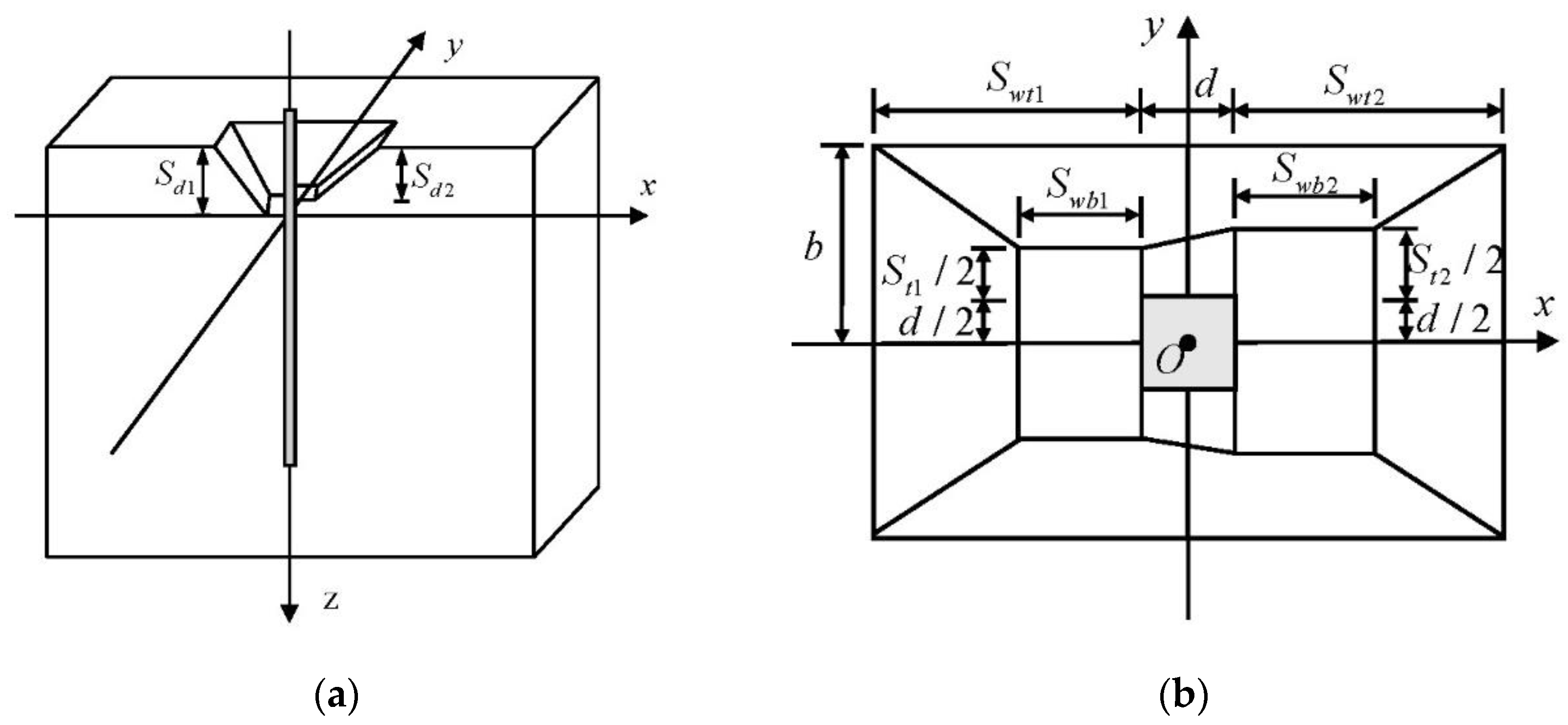
2. Asymmetric Scour Hole Modeling

Differing from the traditional strain wedge model that assumes a linear variation in lateral displacement of a pile with depth, an improved nonlinear strain wedge model was employed [28]. As shown in Figure 1, under the action of a lateral load, the passive compressive soil behind the pile foundation can be regarded as a three-dimensional wedge. The governing differential equation of a laterally loaded single pile is as follows:
E I 4 y 4 z + k i y i = 0
where E I is the flexural stiffness of a single pile, y i is the lateral displacement of the i th layer of a single pile, and z is the depth below the ground surface. The subgrade reaction modulus of the strain wedge at the depth z of any layer is
k i = p i ( y i 1 + y i ) / 2
where p i represents the soil resistance provided via the unit pile length at the i th layer. Drawn from Figure 1a, h is the maximum depth of the wedge, corresponding to the first zero point of the pile displacement curve. The subgrade reaction modulus in the area below the wedge is calculated with k i = η h z i , where η h is the constant of subgrade reaction [21].
Under the action of a lateral load, the three-dimensional wedge with a height of h , a base angle of β m , and a fan angle of φ m is formed in front of the pile foundation in Figure 1a. The wedge changes dynamically with the varying load, for which the base angle β m and fan angle φ m follow. β m = 45 ° + φ m / 2 .
As shown in Figure 1b, the top view of the i th layer wedge satisfies the following equilibrium relationship:
p i = ( Δ σ h ) i B C i S 1 + 2 τ i d S 2
where S 1 and S 2 are pile shape factors for a circular pile, versus S 1 = 0.75 and S 2 = 0.5 for a square pile, S 1 = S 2 = 1.0 , d represents the diameter of a circular pile or the width of the square pile shaft, and ( Δ σ h ) i is the lateral stress increment at the i th layer of the wedge. Using Duncan–Chang model, the stress–strain state of the soil is given as
( Δ σ h ) i = ( σ 1 σ 3 ) i = ε i 1 E ini + ε i ( σ 1 σ 3 ) ult
where ε i represents the lateral strain at the i th layer in the wedge, corresponding to the axial strain in triaxial tests, and E i n i represents the initial tangent modulus during the hyperbolic stage [29]. The asymptotic value of the deviatoric stress ( σ 1 σ 3 ) ult is calculated with
( σ 1 σ 3 ) ult = ( σ 1 σ 3 ) f R f
where R f is the failure ratio, and ( σ 1 σ 3 ) f is the deviatoric stress at failure, calculated as
( σ 1 σ 3 ) f = Δ σ hf = σ v 0 [ tan 2 ( π 4 + φ 2 ) 1 ]
where σ v 0 is the vertical effective stress.
The connection between the sandy mobilized friction angle, φ m i , and the lateral stress change, ( Δ σ h ) i , is established based on the stress level, S L i [30]:
S L i = ( Δ σ h ) i Δ σ hf = [ tan 2 ( π 4 + φ m i 2 ) 1 ] [ tan 2 ( π 4 + φ 2 ) 1 ]
In Equation (3), B C i is the bottom width of the wedge at the i th layer, which is
B C i = d + 2 E F i tan φ m i
where E F i is the vertical distance from the i th layered pile to the failure surface in front of the wedge in Figure 2, φ m i is the sandy mobilized friction angle at the i th layer, and τ i is the lateral shear stress on the pile side at the i th layer in sand [9].
The stain wedge and pile are equally divided into layers with a height of h i , as shown in Figure 2; ε i is the strain of the i th layer soil, y i 1 and y i is the displacement of the single pile at the upper and lower interfaces of the i th layer, respectively. Then, the connection between the pile deflection angle, δ i , and the pile displacement y i of the i th layer is
tan δ i = y i 1 y i h
Corresponding to Figure 1c and Figure 2, the soil strain, ε i , in the depth range of the wedge changes nonlinearly with the depth, which is
ε i = y i 1 + y i 2 E F i
The connection between the pile deflection angle, δ i , of the pile and the lateral soil strain, ε i , and the sandy mobilized friction angle, φ m i , is [31]
δ i = γ i 2 = ( 1 + ν ) ε i 2 cos φ m i
where ν is the Poisson ratio of the soil.
Figure 3 shows the simplified model of the three-dimensional asymmetric local scour hole, where O is the center point of the pile. The geometric parameters include the following: the scour hole width, 2 b ; the upstream scour depth, S d 1 ; the length of the upstream top of the scour hole, S wb 1 ; the width of the upstream bottom of the scour hole, S t 1 ; the length of the upstream bottom of the scour hole, S wt 1 ; the downstream scour depth, S d 2 ; the length of the downstream top of the scour hole, S wb 2 ; the width of the downstream bottom of the scour hole, S t 2 ; the length of the downstream bottom of the scour hole, S wb 2 ; the upstream scour hole slope of the pile foundation, β 1 ; the downstream scour hole slope of the pile foundation, β 2 , and the slope of both sides of the pile foundation, β 3 . The simplified model is symmetrical about the xoz plane in Figure 3a; therefore, only half of the geometric dimensions of the model are marked in Figure 3b and used for calculation [31].
The self-weight of the soil above the xoy plane is equivalent to the external load, and the vertical additional stress term, Δ σ z , is generated at any depth, z , on the xoy plane. Based on the Boussinesq solution, the vertical additional stress of the soil around the pile is expressed as
σ z = 3 P ( x , y ) × z 3 2 π × ( x 2 + y 2 + z 2 ) 5 2 = 3 P ( x , y ) × z 3 2 π × R 5
In the equation,
R = ( x 2 + y 2 + z 2 ) 1 / 2
Under three-dimensional asymmetric local scour conditions, the calculation of vertical effective stress in the soil around the pile is divided into two parts: first, the vertical effective stress generated via the soil below the bottom of the scour hole, and second, the additional stress generated via the soil above the bottom of the scour hole. These are determined via segmental double integration in the x and y directions using Equation (12), with each component shown below:
Δ σ z 1 = 0 d 2 d 2 S t 1 + d 2 3 2 π ( S d 1 S d 2 2 + S d 1 S d 2 d × x ) γ × z 3 R 5 d x d y
Δ σ z 2 = 0 d 2 S t 1 + d 2 λ 1 3 2 π [ ( S d 1 S d 2 2 + S d 1 S d 2 d × x ) - 2 y ( S t 1 + d ) S t 2 S t 1 ( S d 1 S d 2 ) ] γ × z 3 R 5 d x d y
Δ σ z 3 = d 2 2 S w b 2 + d 2 0 S t 1 + d 2 3 2 π ( S d 1 S d 2 ) γ × z 3 R 5 d x d y
Δ σ z 4 = d 2 2 S w b 2 + d 2 S t 1 + d 2 S t 2 + d 2 3 2 π [ ( S d 1 S d 2 ) ( S d 1 S d 2 ) × 2 y ( S t 1 + d ) S t 2 S t 1 ] γ × z 3 R 5 d x d y
Δ σ z 5 = 2 S w b 2 + d 2 2 S w t 2 + d 2 0 S t 1 + d 2 3 2 π [ ( S d 1 S d 2 ) + S d 2 × x ( S w b 1 + d / 2 ) S w t 2 S w b 2 ] γ × z 3 R 5 d x d y
Δ σ z 6 = 2 S w b 2 + d 2 2 S w t 2 + d 2 S t 1 + d 2 λ 2 3 2 π [ ( S d 1 S d 2 ) + x S w b 2 d 2 S w t 2 S w b 2 × S d 2 y ( S t 1 + d ) / 2 b ( S t 1 + d ) / 2 × S d 1 ] γ × z 3 R 5 d x d y
Δ σ z 7 = 2 S w t 1 + d 2 0 S t 1 + d 2 b 3 2 π ( S d 1 × y ( S t 1 + d ) / 2 b ( S t 1 + d ) / 2 ) γ × z 3 R 5 d x d y
Δ σ z 8 = 0 2 S w t 2 + d 2 S t 1 + d 2 b 3 2 π ( S d 1 × y ( S t 1 + d ) / 2 b ( S t 1 + d ) / 2 ) γ × z 3 R 5 d x d y
Δ σ z 9 = 2 S w t 1 + d 2 2 S w b 1 + d 2 0 S t 1 + d 2 3 2 π [ S d 1 × x + ( S w b 1 + d 2 ) S w b 1 S w t 1 ] γ × z 3 R 5 d x d y
Δ σ z 10 = 2 S w t 1 + d 2 2 S w b 1 + d 2 S t 1 + d 2 λ 3 3 2 π [ S d 1 × x + ( S w b 1 + d / 2 ) S w b 1 S w t 1 S d 1 × 2 y ( S t 1 + d ) 2 b ( S t 1 + d ) ] γ × z 3 R 5 d x d y
Δ σ z 11 = d 2 0 0 S t 1 + d 2 3 2 π ( S d 1 S d 2 2 + S d 1 S d 2 2 × 2 x d ) γ × z 3 R 5 d x d y
Δ σ z 12 = d 2 0 S t 1 + d 2 λ 4 3 2 π [ S d 1 S d 2 2 + S d 1 S d 2 2 × 2 x d ( S d 1 S d 2 ) × 2 y ( S t 1 + d ) S t 2 S t 1 ] γ × z 3 R 5 d x d y
Δ σ z 13 = 2 S w t 1 + d 2 0 b 3 2 π S d 1 × γ × z 3 R 5 d x d y
Δ σ z 14 = 0 + b + 3 2 π S d 1 × γ × z 3 R 5 d x d y
Δ σ z 15 = 2 S w t 2 + d 2 + 0 b 3 2 π S d 1 × γ × z 3 R 5 d x d y
In the equation,
λ 1 = S t 2 S t 1 2 d × x + S t 1 + S t 2 + 2 d 4
λ 2 = b ( S t 2 + d ) / 2 S w t 2 S w b 2 x + b b ( S t 2 + d ) / 2 S w t 2 S w b 2 × ( S w t 2 + d 2 )
λ 3 = 2 b S t 1 d 2 ( S w b 1 S w t 1 ) ( x + S w t 1 + d 2 ) + b
λ 4 = S t 2 S t 1 2 d × x + S t 1 + S t 2 + 2 d 4
The vertical effective stress of the soil around the pile at any depth, z , is
σ z = 2 Δ σ z + γ z
where σ z is equivalent to σ v 0 in the strain wedge model, and Δ σ z is the superposition of Equations (14)–(28).

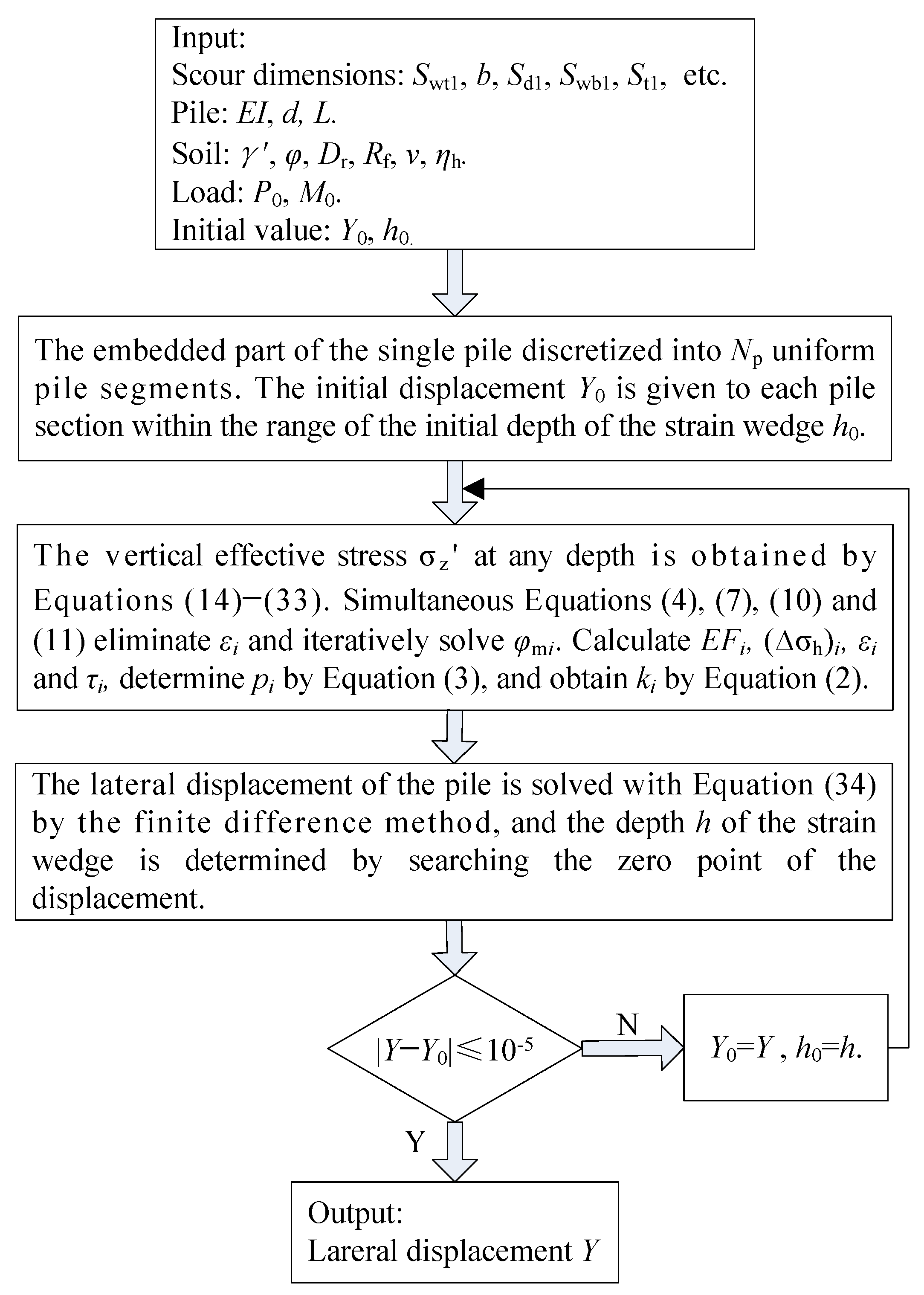
3. Calculation Process

After discretizing the embedded part of a single pile with length L into N p uniform pile segments and incorporating boundary conditions, the finite difference method is used to solve Equation (1), resulting in the equation system as
K Y = F
which contains a stiffness matrix, K , of size ( N p + 1 ) × ( N p + 1 ) , the displacement vector Y , and the lateral load vector F , both of size ( N p + 1 ) .
When using the calculation method for various stress components in the soil around the pile under the condition of three-dimensional asymmetric local scour based on the Boussinesq solution, the vertical effective stress at any depth around the pile is calculated. Then, a simplified model for a single pile under a three-dimensional asymmetric local scour condition is established using the strain wedge model. A numerical calculation program can be developed to perform the calculations, and the detailed process is shown in Figure 4.

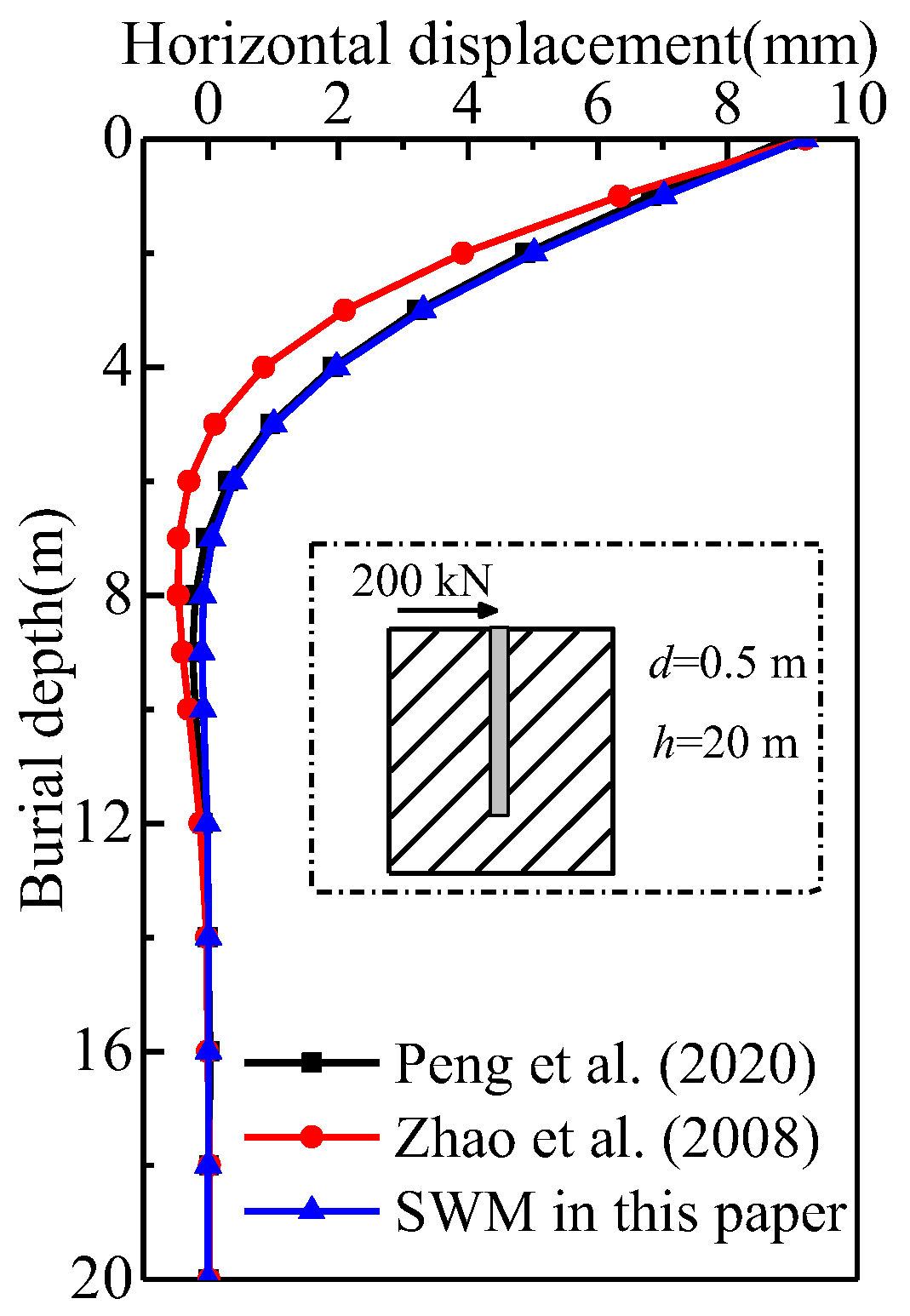
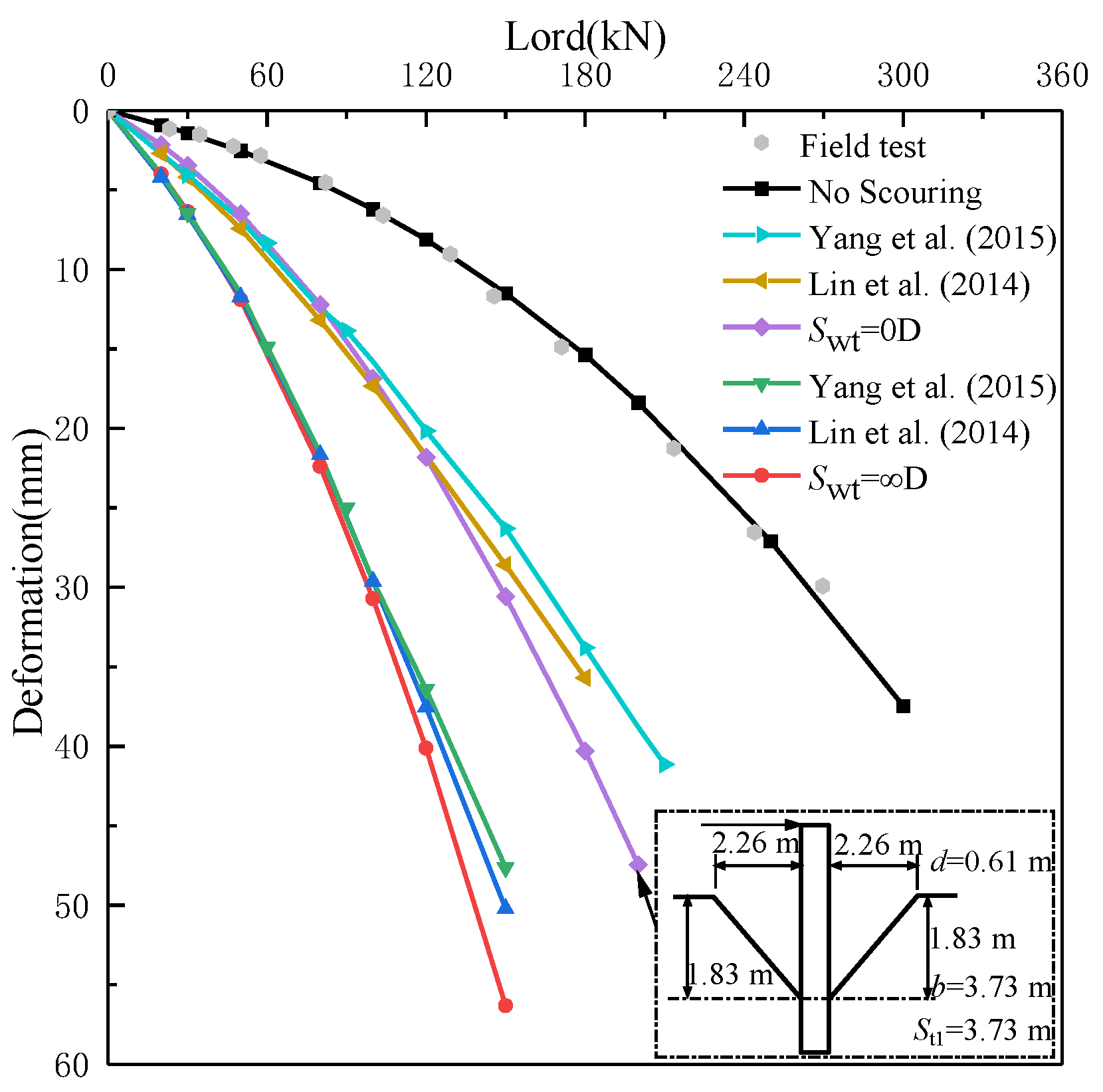
4. Theoretical Verification

In the example of a certain cast-in-place reinforced concrete pile [32], Table 1 provides the physical and mechanical parameters of a single pile and the surrounding soil. The displacement curve of the pile obtained using the modified strain wedge method (SWM) is compared with the results from references [22,32] to validate the accuracy of the SWM method. It is evident that the displacement curve obtained using the SWM method exhibits a similar variation trend to the results in references [22,32], and the displacement values are highly consistent in Figure 5.
To verify the correctness of the SWM method under the condition of three-dimensional asymmetric local scour, the calculation results of the proposed method are compared with those of the simplified method [7] and the equivalent-strain wedge method [28] using the parameters given in Table 2 and Table 3.
Figure 6 demonstrates the excellent agreement between the groundline displacement obtained through the calculation method proposed in this paper and the results from the field test [7]. The figure unmistakably demonstrates that, with an increase in the scouring size, there is a remarkable escalation in the groundline displacement. When factoring in the scour effect, it becomes apparent that the calculation results in this paper closely align with those results in the references [7,28] when the groundline displacement of the pile is maintained within the 20 mm range. However, when the groundline displacement exceeds 20 mm, the calculated lateral bearing performance appears to be lower. The primary reason behind this discrepancy could be attributed to the continuous compression and densification of the passive soil in front of the pile during the actual loading process. Consequently, the soil stiffness increases, leading to an enhanced bearing performance on the side of the pile. However, this paper does not take into account this particular effect. Figure 3b shows a simplified model of three-dimensional asymmetric local scour around the pile. Compared to references [7,28], the proposed method considers the impact of the scouring sizes on the response of a single pile under the asymmetric scour condition. Therefore, the scour pattern selected is more flexible and realistic.

5. Parametric Analysis
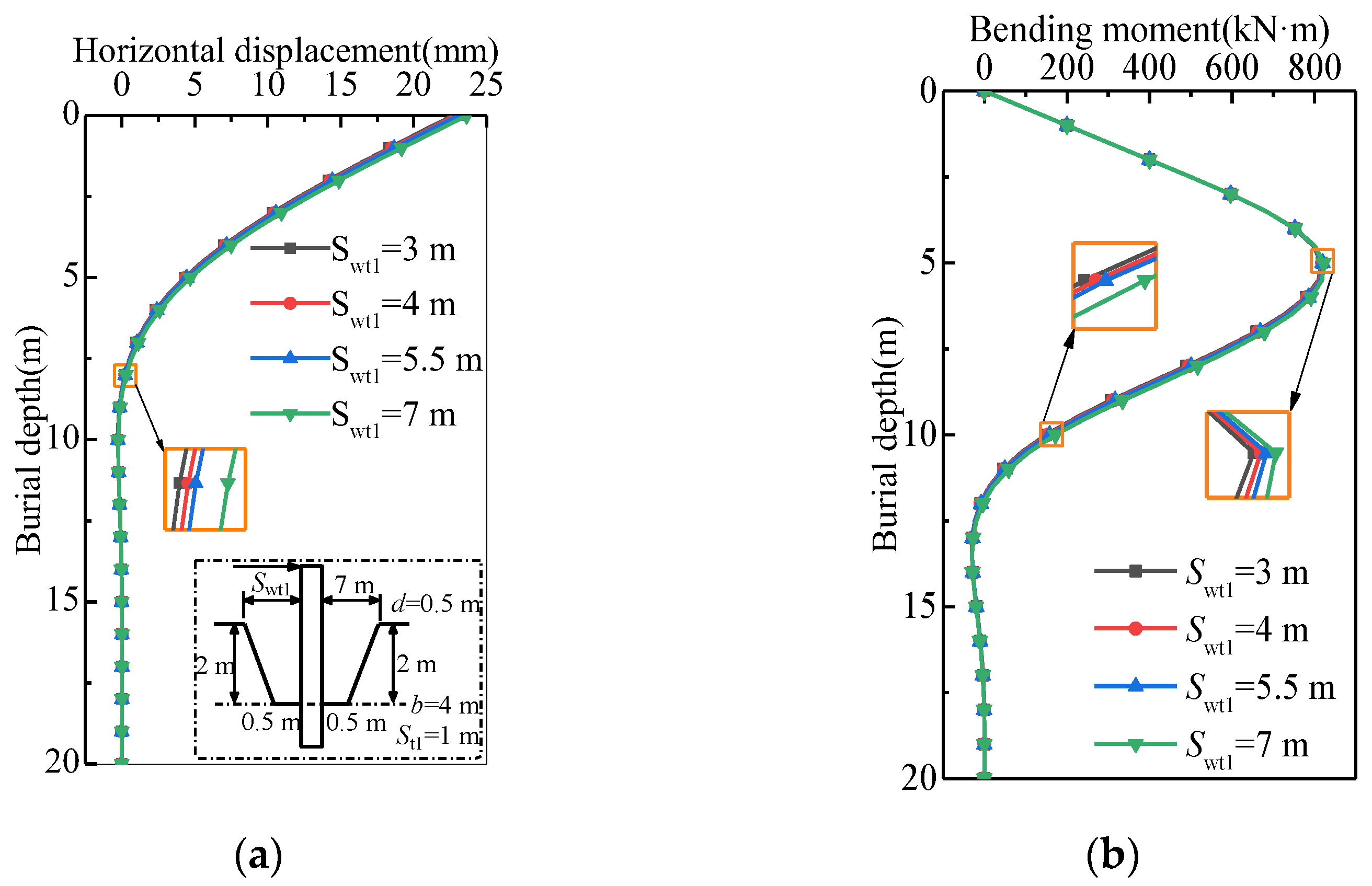
Two key points were selected for analysis to intuitively reflect the impact of three-dimensional asymmetric scour on the lateral bearing performance of a single pile, namely the lateral displacement and the bending moment. The buried depth of a single pile corresponds to the surface position before scouring, and a certain engineering pile was still selected as the calculation object [32]. Because the scour slope and depth upstream of a single pile are larger than those downstream, the positive direction of the lateral load should be the upstream side of the single pile in the parameter analysis. Based on the model, several independent variables directly related to the three-dimensional asymmetric local scour and scouring action were considered: the length of the upstream top of the scour hole, S wt 1 ; the upstream scour depth, S d 1 ; the downstream scour depth, S d 2 ; the length of the upstream bottom of the scour hole, S wb 1 ; the width of the upstream bottom of the scour hole, S t 1 ; and the scour hole width, 2 b . The study aimed to explore the impact of scouring action on the lateral bearing performance of a single pile.

5.1. Effect of S wt 1

To determine the effect of S wt 1 , parameter analysis was performed by changing S wt 1 (using 3 m, 4 m, 5.5 m, and 7 m widths) while keeping the other parameters constant, Figure 7 shows the lateral displacement and internal force diagram calculated under different S wt 1 values. As shown in Figure 7a, it is noticeable that, when the buried depth is less than 10 m, the lateral displacement values of piles at different S wt 1 values are quite close. This suggests that the impact of local scour on the lateral displacement of a single pile is limited to a specific depth so that the effect of S wt 1 below that depth can be ignored. The top area of the upstream scour hole increases from 24 m2 to 56 m2 while keeping the other parameters constant, and the lateral displacement of the single pile will increase. It can be seen from Figure 7b that the change in S wt 1 has the most significant influence on the bending moment of the pile body in the range of 5–12.5 m. When S wt 1 increases by 1.3, 1.8, and 2.3 times, respectively, while the other parameters remain constant, the lateral displacement of a single pile at the groundline increases by 0.90%, 1.67%, and 4.27%, respectively. Overall, the existence of an asymmetric scour hole shape leads to a difference in pile deformation, which means that the upstream and downstream of the pile are eroded to varying degrees. This phenomenon leads to the difference in soil pressure between the upstream and downstream of the pile, resulting in a large horizontal stress difference, so the pile will undergo greater bending displacement. Therefore, the geometric shape of the asymmetric scour hole shows a greater influence on the deformation response of the horizontal load pile. Because, in many design standards, the scour hole formed around the pile is usually idealized as a symmetrical shape, obviously, the assumption of a symmetrical scour hole is relatively unsafe. To ensure the safe operation of offshore wind turbines and bridge structures, it is crucial to account for the asymmetric geometry of a scour hole in pile foundation design.

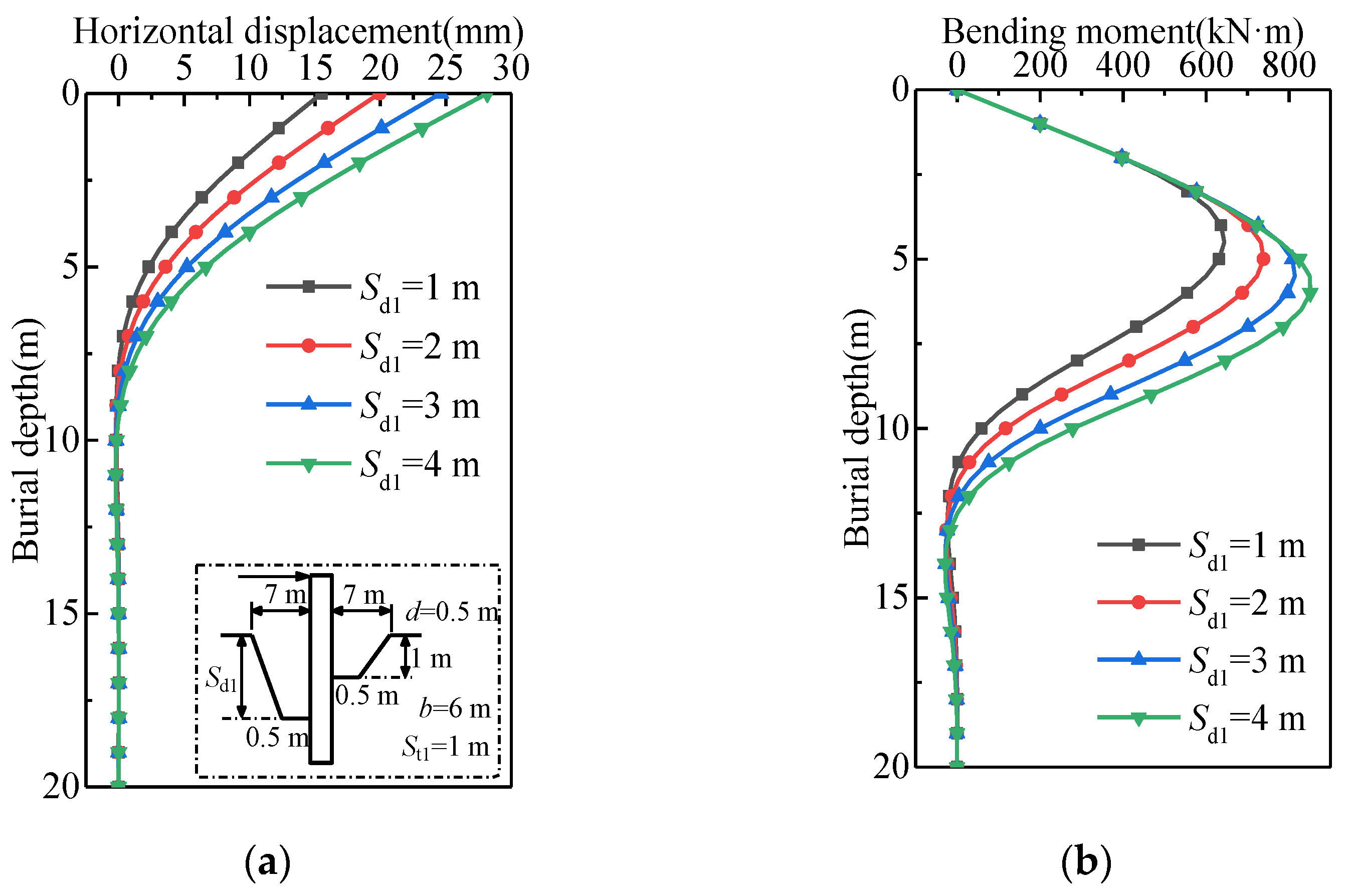
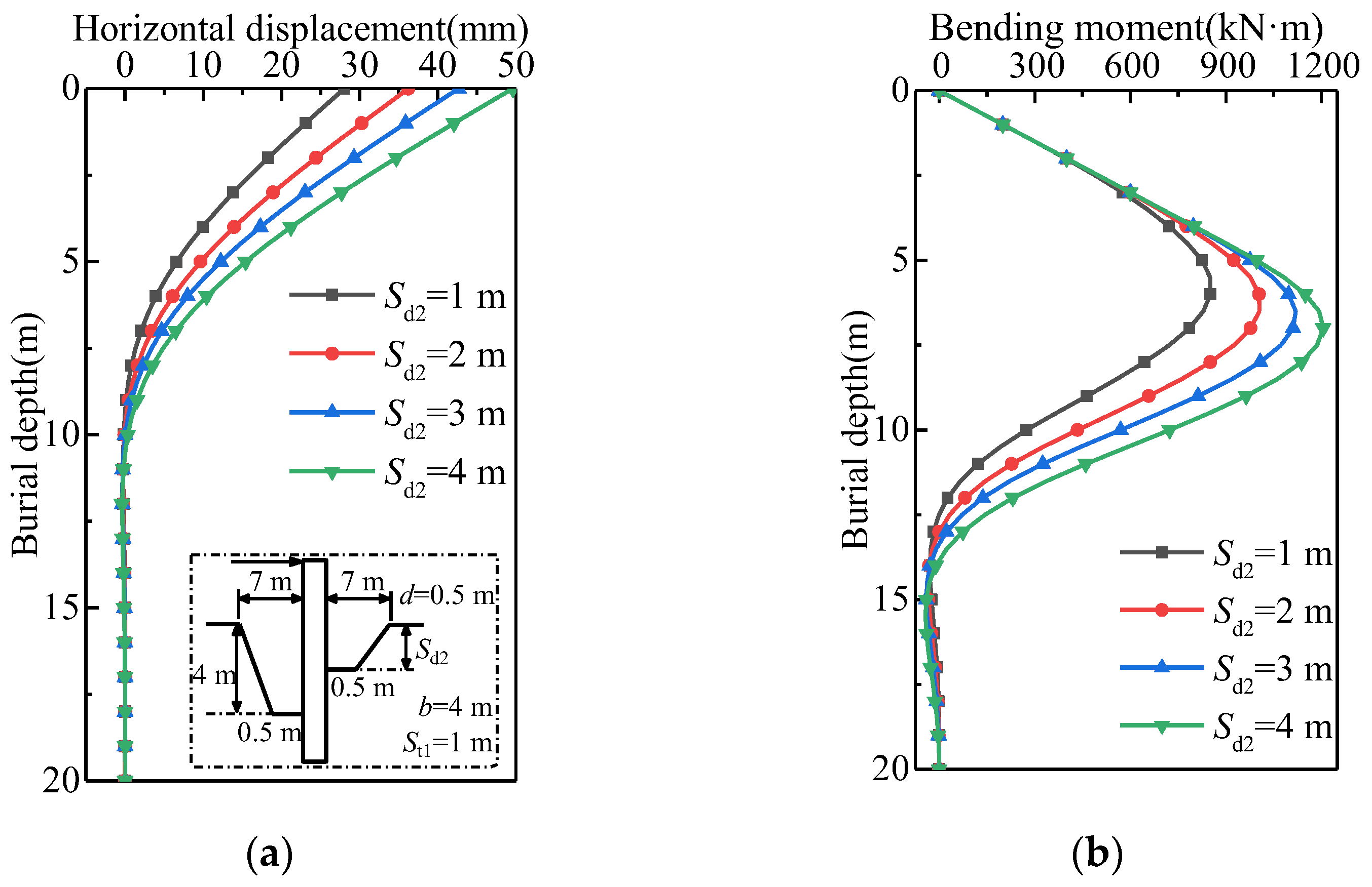
5.2. Effect of Scour Depth

Illustrated in Figure 3a, in the context of three-dimensional asymmetric local scour where the scouring depth, S d 1 , exceeds S d 2 , fixed constraints are applied to the partially embedded pile section from ( S d 1 S d 2 ) m to 0 m in the z direction. The vertical effective stress at any depth, z , within this partially embedded portion is linearly interpolated utilizing the vertical effective stress values at ( S d 1 S d 2 ) m and 0 m.
To determine the effect of the scour depth, parameter analysis was performed by changing the scour depth (using 2.0 D, 4.0 D, 6.0 D, and 8.0 D depths) while keeping other parameters constant; Figure 8 and Figure 9 show the lateral displacement and internal force diagrams calculated under different upstream scour depth S d 1 values and the downstream scour depth S d 2 , respectively. With the increase in S d 1 from 2.0 D to 8.0 D, the maximum bending moment of the pile gradually moves down from 9 D to 12 D from the top of the pile. The reason for these results Is that, with the increase in the scour depth, the loss of sand around the pile increases, so the constraint of the soil on the pile is weakened. With the increase in the scour depth S d 1 from 2.0 D to 8.0 D, the maximum bending moment increases from 643.9 kN·m to 851.4 kN·m (an increase of 32.2%). Moreover, it can be noted that the zero points of bending moment are located at 22 D, 23 D, 24 D, and 25 D respectively. As S d 2 increases, the point of contraflexure of the pile moves downward. As S d 2 increases by 1, 2, and 3 times, while keeping the other parameters constant, the groundline displacement of the pile increases by 29.43%, 52.22%, and 76.95%, respectively. Through a comparison between the curves depicted in Figure 8a,b and Figure 9a,b the consistent trend shows that the influence of the scour depth on the lateral deformation and internal force of a single pile is particularly obvious. The reason for these results is that, with the increase in the scour depth, the soil around the pile is scoured and lost, and the lateral resistance provided via the soil on the pile side disappears. It can be seen that the existence of an asymmetric scour hole leads to a difference in pile displacement. This phenomenon leads to a large horizontal stress difference in the pile body, so the pile will undergo significant bending displacement. Therefore, in the design of an offshore pile foundation, it is particularly important to strengthen the maximum bending moment of the pile. Anti-scouring materials are used to cover the surface around the pile foundation, such as rock filling and a protective concrete wall, so as to reduce erosion via water flow to the soil around the pile foundation, avoid the deepening of the scour depth around the pile and improving the lateral bearing performance of the pile foundation.

5.3. Effect of S wb 1

The parameters of the three-dimensional scour hole size are as follows: S wt 1 = S wt 2 = 7     m , S wb 2 = 0.5     m , S d 1 = S d 2 = 2     m , and S t 1 = 1     m , b = 4     m . Table 4 shows the lateral displacement and internal force data of a single pile with different upstream bottom lengths of the scour hole while keeping the other parameters constant. From the Table 4, it is discernible that, as S wb 1 rises, both the lateral displacement and bending moment of the pile exhibit a tendency to ascend. At a burial depth of 6 m, for S wb 1 increments of 1 time, 4 times, and 8 times, the corresponding lateral displacement and bending moment of a single-pile register increases by roughly 0.41%, 1.65%, and 2.06% and 0.15%, 0.38%, and 0.43%, respectively. Obviously, the length of the upstream bottom of the scour hole, S wb 1 , has less of an influence on the lateral bearing performance of the pile than the scour depth.

5.4. Effect of S t 1

To determine the effect of S t 1 , parameter analysis was performed via a change (using 0 m, 1 m, 2 m, and 3 m widths) while keeping the other parameters constant. Figure 10 shows the lateral displacement and internal force diagram calculated under different S t 1 values. Figure 10a reveals that the lateral displacement of a single pile at a given buried depth increases with the increase in S t 1 . When drawing insight from Figure 10b, it becomes clear that, within the burial depth range of 5 to 12.5 m, the variation in S t 1 exerts the most pronounced effect on the pile’s bending moment. The reason for these findings is that, as S t 1 increases, the slopes, β 3 , on both sides of the scour hole are elevated, consequently prompting the point of contraflexure of the pile to shift downward.

5.5. Effect of 2 b

To determine the effect of 2 b , parameter analysis was performed via a change (using 4 m, 6 m, 8 m, and 12 m widths) while keeping the other parameters constant. Figure 11 shows the lateral displacement and internal force diagram calculated under different 2 b values. In Figure 11a, it is noticeable that, within the range of influence when keeping the burial depth constant, increasing the top area of the upstream scour hole from 28 m2 to 84 m2 brings about a notable increase in the lateral displacement of a single pile. Figure 11b emphasizes that the influence of 2 b on the bending moment of the single pile is the most significant in the range of buried depth of 5–10 m. As 2 b increases, the pile’s point of contraflexure shifts downward.
Analyzing Figure 8 and Figure 9 reveals that the fluctuation in the scour hole width, 2 b , exerts a comparatively minor effect on the lateral displacement and internal forces of the single pile in contrast to variations in the scour depth. Further insights are drawn from Table 5, which outlines additional stresses on the soil encircling the pile at the bottom of the scour hole, considering different widths of the upstream bottom, S t 1 , and scour hole widths, 2 b . From the table, it is evident that, with 2 times, 4 times, and 6 times expansion in the upstream bottom area of the scour hole, the additional stresses on the soil around the pile at the bottom of scour hole plummet by approximately 72.52%, 80.50%, and 82.59%, respectively. When the upstream top area of the scour hole grows by 0.5 times, 1.25 times, and 2 times, the additional stresses on the soil around the pile at the bottom of the scour hole lessen by around 33.65%, 52.94%, and 61.45%, respectively. When maintaining a constant scour depth, the changes in the upstream bottom area of the scour hole exert a more pronounced influence on the lateral displacement capability of the single pile compared to alterations in the upstream top area of the scour hole. Moreover, this method can quantitatively evaluate the change in the additional stress of pile-side soil, which is of guiding significance for further study and the evaluation of the effectiveness of different scour reduction techniques in various cases. In practice, the scour around the pile can be regularly detected. The diversion structure can be set around the pile to guide the water flow away from the pile, reducing the scour effect and protecting the stability of the pile foundation. The timely resolution of any erosion problems through maintenance activities is critical to maintaining the lateral bearing performance of the pile and ensuring the long-term effectiveness of the protection measures.

6. Conclusions

The simplified calculation method for three-dimensional asymmetric local scour based on the improved strain wedge model combined with the Boussinesq solution was used to reflect the influence of scouring on the lateral bearing performance of a pile foundation at an asymmetric local scour site. In the design of the pile foundation, the three-dimensional scour hole size parameters can be considered to optimize the pile foundation, and the decision-making process can be guided when studying the risk related to the scour and its potential impact on the lateral bearing performance. After the accuracy of the proposed method was verified, the influence of the three-dimensional asymmetric local scour size on the lateral bearing performance of a single pile was investigated. The key conclusions of the study are as follows:
  • The approach offers a comprehensive means to unveil the ramifications of three-dimensional asymmetric local scour on the lateral bearing performance of a single pile;
  • Through an analysis of the scouring dimensions, it becomes evident that alterations in the scour depth and scour bottom area exert a substantial influence on the lateral displacement and bending moment of a single pile;
  • With the expansion of the scour dimensions, the lateral displacement of a single pile undergoes an increase within the impacted depth range, concurrently leading to a reduction in its lateral bearing performance;
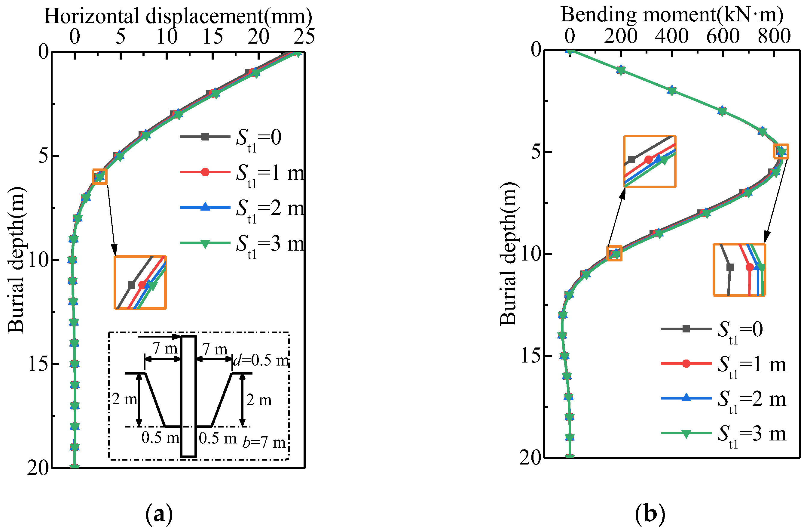
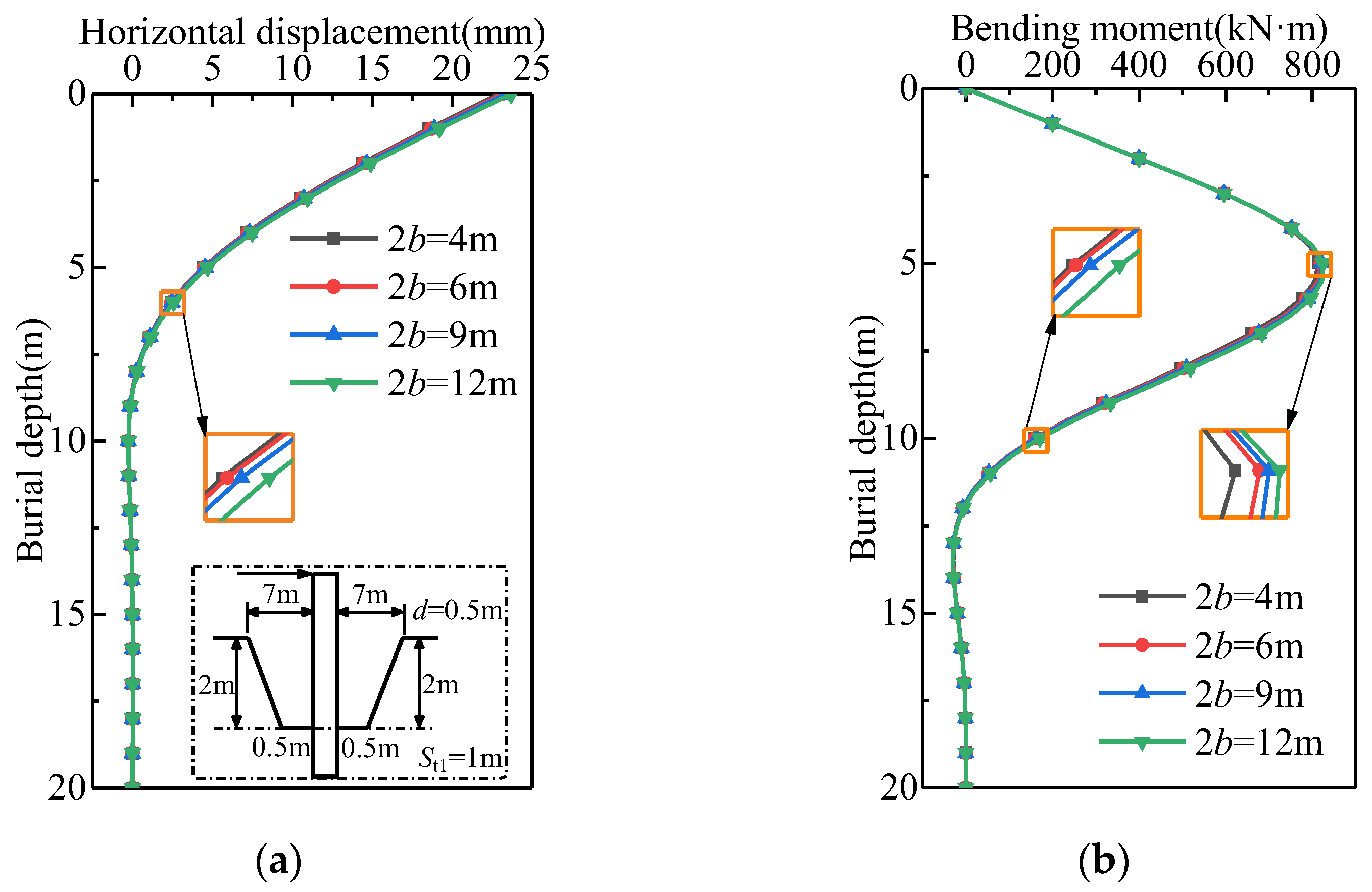
  • With an increase in the upstream bottom width, S wb 1 , the lateral displacement of a single pile within the impacted depth range increases. At a burial depth of 6 m, the corresponding lateral displacement and bending moment of a single pile increase by 0.41%, 1.65%, and 2.06% and 0.15%, 0.38%, and 0.43%, respectively, when S wb 1 increases by two times, four times, and eight times.
At present, the theoretical analysis of a single pile’s response under cyclic loading conditions with three-dimensional asymmetric local scour remains unresolved. Under the action of a cyclic load, the stiffness of the soil around the pile is weakened, and the pile foundation may produce cumulative deformation. Therefore, it is necessary to introduce the soil stiffness attenuation model under the cyclic load. Combined with the method in this paper, the lateral bearing performance of a single pile placed at an asymmetric scour hole site under a cyclic load will be studied. Laboratory experiments will be carried out to simulate single piles placed in a three-dimensional asymmetric scour hole site under cyclic loading. These experiments can help verify the method in this paper and provide parameters for a numerical simulation to ensure the applicability of the research results.

Author Contributions

Conceptualization, J.M.; methodology, J.M. and S.W.; software, S.W.; validation, S.W., C.W. and F.L.; formal analysis, J.M. and C.W.; investigation, J.M. and S.W.; resources, J.M.; data curation, S.W.; writing—original draft preparation, J.M. and S.W.; writing—review and editing, J.M., S.W. and C.W.; visualization, J.M. and D.L.; supervision, S.W.; project administration, J.M. and F.L.; funding acquisition, J.M., F.L. and D.L. All authors have read and agreed to the published version of the manuscript.

Funding

This research was funded by the National Natural Science Foundation of China (grant number 11502072), the Key R&D and Promotion Special Project in Henan Province-Science and Technology Research Project (grant number 222102320462), and the Key R&D and Promotion Special Project in Henan Province-Science and Technology Research (joint fund) Project (grant number 232103810082).

Institutional Review Board Statement

Not applicable.

Informed Consent Statement

Not applicable.

Data Availability Statement

The original contributions presented in the study are included in the article, further inquiries can be directed to the corresponding author.

Acknowledgments

The authors greatly appreciate the comments from the reviewers, whose comments helped improve the quality of the paper.

Conflicts of Interest

The authors declare no conflicts of interest.

References

  1. Dai, G.L.; OuYang, H.R.; Gao, L.C.; Guo, Q.; Gong, W.M. Experimental study on monotonic and cyclic lateral behavior enhancing mechanism of semi-rigid pile under different foundation reinforced methods in clay. Ocean Eng. 2023, 273, 113955. [Google Scholar] [CrossRef]
  2. Tott-Buswell, J.; Prendergast, L.J.; Gavin, K.A. CPT-based multi-spring model for lateral monopile analysis under SLS conditions in sand. Ocean Eng. 2024, 293, 116642. [Google Scholar] [CrossRef]
  3. Gupta, B.K.; Basu, D. Offshore wind turbine monopile foundations: Design perspectives. Ocean Eng. 2020, 213, 107514. [Google Scholar] [CrossRef]
  4. Malakshah, R.R.; Moradi, M.; Mehrabadi, A.R.; Ghalandarzadeh, A. Scour effects on monopile lateral behavior under cyclic and monotonic loading. Ocean Eng. 2023, 269, 113396. [Google Scholar] [CrossRef]
  5. Kishore, Y.N.; Rao, S.N.; Mani, J.S. The behavior of laterally loaded piles subjected to scour in marine environment. KSCE J. Civ. Eng. 2009, 13, 403–408. [Google Scholar] [CrossRef]
  6. Li, F.; Han, J.; Lin, C. Effect of Scour on the Behavior of Laterally Loaded Single Piles in Marine Clay. Mar. Georesour. Geotechnol. 2013, 31, 271–289. [Google Scholar] [CrossRef]
  7. Lin, C.; Han, J.; Bennett, C.; Parsons, R.L. Analysis of Laterally Loaded Piles in Sand Considering Scour Hole Dimensions. J. Geotech. Geoenviron. 2014, 140, 04014024. [Google Scholar] [CrossRef]
  8. Zhang, H.; Chen, S.L.; Liang, F.Y. Effects of scour-hole dimensions and soil stress history on the behavior of laterally loaded piles in soft clay under scour conditions. Comput. Geotech. 2017, 84, 198–209. [Google Scholar] [CrossRef]
  9. Yang, X.F.; Zhang, C.R.; Huang, M.S.; Yuan, J.Y. Lateral loading of a pile using strain wedge model and its application under scouring. Mar. Georesour. Geotechnol. 2017, 36, 340–350. [Google Scholar] [CrossRef]
  10. Zhu, J.; Wang, Y.W.; Li, Y.L.; Zheng, K.F.; Heng, J.L. Scour effect on a sea-crossing bridge under combined action of service and extreme seismic loads. J. Cent. South Univ. 2022, 29, 2719–2742. [Google Scholar] [CrossRef]
  11. Liang, F.Y.; Yuan, Z.C.; Liang, X.; Zhang, H. Seismic response of monopile-supported offshore wind turbines under combined wind, wave and hydrodynamic loads at scoured sites. Comput. Geotech. 2022, 144, 104640. [Google Scholar] [CrossRef]
  12. Ma, J.J.; Han, S.J.; Gao, X.J.; Li, D.; Guo, Y.; Liu, Q.J. Dynamic Lateral Response of the Partially-Embedded Single Piles in Layered Soil. Appl. Sci. 2022, 12, 1504. [Google Scholar] [CrossRef]
  13. Lin, Y.J.; Lin, C. Effects of scour-hole dimensions on lateral behavior of piles in sands. Comput. Geotech. 2019, 111, 30–41. [Google Scholar] [CrossRef]
  14. Yu, T.S.; Zhang, Y.T.; Zhang, S.B.; Shi, Z.Y.; Chen, X.G.; Xu, Y.; Tang, Y.Y. Experimental study on scour around a composite bucket foundation due to waves and current. Ocean Eng. 2019, 189, 106302. [Google Scholar] [CrossRef]
  15. Zhu, B.; Li, T.; Xiong, G.; Liu, J.C. Centrifuge model tests on laterally loaded piles in sand. Int. J. Phys. Model. Geo. 2016, 16, 160–172. [Google Scholar] [CrossRef]
  16. Chortis, G.; Askarinejad, A.; Prendergast, L.J.; Li, Q.; Gavin, K. Influence of scour depth and type on p-y curves for monopiles in sand under monotonic lateral loading in a geotechnical centrifuge. Ocean Eng. 2020, 197, 106838. [Google Scholar] [CrossRef]
  17. Zhang, F.; Dai, G.L.; Gong, W.M. Analysis solution of the lateral load response of offshore monopile foundations under asymmetric scour. Ocean Eng. 2021, 239, 109826. [Google Scholar] [CrossRef]
  18. Zhang, F.; Dai, G.L.; Gong, W.M. Analytical method for laterally loaded piles in soft clay considering the influence of soil outside the scour hole on the effective overburden pressure. Acta Geotech. 2021, 16, 2963–2974. [Google Scholar] [CrossRef]
  19. Xu, L.Y.; Cai, F.; Wang, G.X.; Ugai, K. Nonlinear analysis of laterally loaded single piles in sand using modified strain wedge model. Comput. Geotech. 2013, 51, 60–71. [Google Scholar] [CrossRef]
  20. Xu, L.Y.; Cai, F.; Xue, Y.Y. Implementation of state-dependent plasticity model in strain wedge model for laterally loaded piles in sand. Mar. Georesour. Geotechnol. 2018, 37, 622–632. [Google Scholar] [CrossRef]
  21. Abbasi, H.; Binesh, S.M.; Lashkari, A. Using a state-dependent constitutive model in strain wedge method for laterally loaded piles in sand. Soils Found. 2019, 59, 271–283. [Google Scholar] [CrossRef]
  22. Peng, W.Z.; Zhao, M.H.; Yang, C.W.; Liu, Y.N. Modification of strain wedge model for soil resistance in front of piles in sloping ground. J. Cent. South Univ. (Sci. Technol.) 2020, 51, 1936–1945. [Google Scholar]
  23. Zhang, X.; Liu, Y.; Hu, Z.P.; Zhang, Y.G.; Huang, P. Ultimate lateral resistance of piles in sand based on the modified strain wedge model. Mar. Georesour. Geotechnol. 2022, 40, 690–700. [Google Scholar] [CrossRef]
  24. Xu, F.; Dai, G.L.; Gong, W.M.; Zhao, X.L.; Zhang, F. Lateral Loading of a Rock-Socketed Pile Using the Strain Wedge Model Based on Hoek-Brown Criterion. Appl. Sci. 2022, 12, 3495. [Google Scholar] [CrossRef]
  25. Wang, L.X.; Liu, X.; Wu, W.B.; El Naggar, M.H.; Mei, G.X.; Wen, M.J.; Xu, M.J.; Liu, H.; Lu, C.H. Nonlinear analysis of laterally loaded single pile in layered soil based on conical strain wedge model. Ocean Eng. 2023, 280, 114699. [Google Scholar] [CrossRef]
  26. Wang, L.X.; Wu, W.B.; Naggar, M.H.E.; Zhang, Y.P.; Liu, X.; Sun, J. Scoured failure wedge model for analysis of scoured pile-soil interaction in sand. Comput. Geotech. 2024, 166, 105981. [Google Scholar] [CrossRef]
  27. Zhang, F.; Dai, G.L.; Gong, W.M.; Liu, J.H. Curved Strain Wedge Analysis of Laterally Loaded Flexible Piles in Various Soil Types. J. Geotech. Geoenviron. Eng. 2022, 148, 04022037. [Google Scholar] [CrossRef]
  28. Yang, X.F.; Zhang, C.R.; Yuan, J.Y. Equivalent-strain wedge method for laterally loaded pile in sand considering scouring effect. Rock Soil Mech. 2015, 36, 2946–2950. [Google Scholar]
  29. Byrne, P.M.; Cheung, H.; Yan, L. Soil parameters for deformation analysis of sand masses. Can. Geotech. J. 1987, 24, 366–376. [Google Scholar] [CrossRef]
  30. Ashour, M.; Norris, G.; Pilling, P. Lateral loading of a pile in layered soil using the strain wedge model. J. Geotech. Geoenviron. Eng. 1998, 124, 303–315. [Google Scholar] [CrossRef]
  31. Zhou, H.; Wang, Z.L.; Liu, H.L.; Ding, X.M.; Wu, D.F.; Liu, M.Y.; Chen, Z.X. Analytical Solution of Soil Stress Variation Under Condition of Asymmetric Local Scour of Pile Foundation. China J. Highw. Transp. 2021, 34, 72–82. [Google Scholar]
  32. Zhao, M.H.; Liu, D.P.; Zou, X.J. Analysis of pile-soil interaction under horizontal load by meshless method. Rock Soil Mech. 2008, 29, 2476–2480. [Google Scholar]
Figure 1. Strain wedge model: (a) three-dimensional view, (b) top view, and (c) side view.
Applsci 14 03056 g001
Figure 2. Nonlinear displacement in wedge.
Applsci 14 03056 g002
Figure 3. Three-dimensional asymmetric local scour hole simplified model: (a) sectional view and (b) plan view.
Applsci 14 03056 g003
Figure 4. Flow chart of the simplified model.
Applsci 14 03056 g004
Figure 5. Lateral displacement curves of single pile, Peng et al. [22]; Zhao et al. [32].
Applsci 14 03056 g005
Figure 6. Comparison of the proposed method with the results of references [7,28].
Applsci 14 03056 g006
Figure 7. Lateral bearing performance of pile at varying S w t 1 values: (a) lateral displacement curves and (b) bending moment curves.
Applsci 14 03056 g007
Figure 8. Lateral bearing performance of pile at varying S d l values: (a) lateral displacement curves and (b) bending moment curves.
Applsci 14 03056 g008
Figure 9. Lateral bearing performance of pile at varying S d 2 values: (a) lateral displacement curves and (b) bending moment curves.
Applsci 14 03056 g009
Figure 10. Lateral bearing performance of pile at varying S t l values: (a) lateral displacement curves and (b) bending moment curves.
Applsci 14 03056 g010
Figure 11. Lateral bearing performance of pile at varying 2 b values: (a) lateral displacement curves and (b) bending moment curves.
Applsci 14 03056 g011
Table 1. Physical parameters of a single pile and the surrounding soil.
Physical MeaningNumerical Value
Lateral load at the top of the pile/kN200
Length, L /m20
Diameter, d /m0.5
Flexural stiffness, E I /kN·m21.17 × 106
Cohesive force, c /kPa0
Relative density, D r /%65
Poisson ratio of the pile, ν 0.2
Poisson ratio of soil, ν s 0.25
Table 2. Physical parameters of single pile and soil.
Physical MeaningNumerical Value
Type of pile foundationSteel pipe pile
Length, L /m21.3
Diameter, d /m0.61
Wall thickness, t /m0.0095
Flexural stiffness, E I /MN·m2163.32
Foundation typeSaturated medium-density fine sand
Effective gravity, γ /kN/m310.4
Internal friction angle, φ 39
Relative density, D r /%60
Poisson ratio of the pile, ν 0.3
Table 3. Three-dimensional asymmetric local scour hole parameters.
Physical MeaningNumerical Value
Width of upstream bottom of pile foundation, S t 1 /m1
Width of scour hole, 2 b /m7.46
Slope of upstream scour hole of pile foundation, β 1 39
Slope of downstream scour hole of pile foundation, β 2 39
Slope on both sides of pile foundation, β 3 32
Table 4. Impact of S wb 1 on displacement and internal force of single pile.
Burial Depth (m)Displacement (mm)Bending Moment (kN·m)
S wb 1 = 0.5   m S wb 1 = 1   m S wb 1 = 2.5   m S wb 1 = 4.5   m S wb 1 = 0.5   m S w b 1 = 1   m S wb 1 = 2.5   m S w b 1 = 4.5   m
023.1723.2223.3323.370.000.000.000.00
214.5214.5614.6414.67400.00400.00400.00400.00
47.237.267.327.33752.19752.37752.53752.59
62.432.442.472.48788.80790.01791.78792.22
80.230.230.240.25504.97506.53509.76510.67
10−0.26−0.26−0.26−0.26159.89160.76163.20163.99
12−0.15−0.15−0.15−0.15−8.00−7.83−7.16−6.92
14−0.03−0.03−0.03−0.03−28.36−28.42−28.51−28.52
160.010.010.010.01−10.18−10.23−10.36−10.40
180.010.010.010.01−0.63−0.64−0.67−0.68
200.000.000.000.000.000.000.000.00
Table 5. Additional soil stress around a pile with varying St1 and 2 b values at the same buried depth.
St1 Value(m)Additional Stress (kN/m2)2b Value (m)Additional Stress (kN/m2)
00.11440.089
10.03160.059
20.02290.042
30.020120.034
Disclaimer/Publisher’s Note: The statements, opinions and data contained in all publications are solely those of the individual author(s) and contributor(s) and not of MDPI and/or the editor(s). MDPI and/or the editor(s) disclaim responsibility for any injury to people or property resulting from any ideas, methods, instructions or products referred to in the content.

