
A Review of Small-Scale Vapor Compression Refrigeration Technologies


Abstract
:1. Introduction
2. Small-Scale Refrigeration Technologies
2.1. Passive Technologies
2.2. Active Technologies
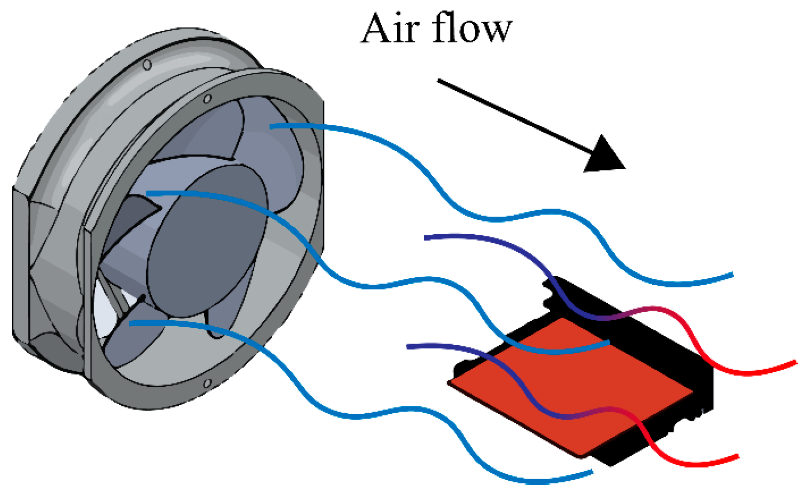
2.2.1. Forced Convection
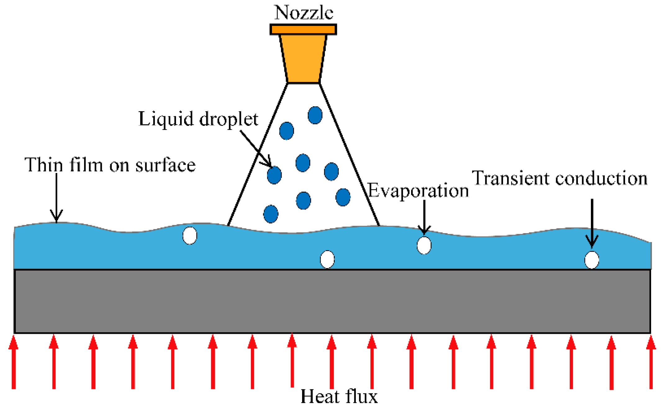
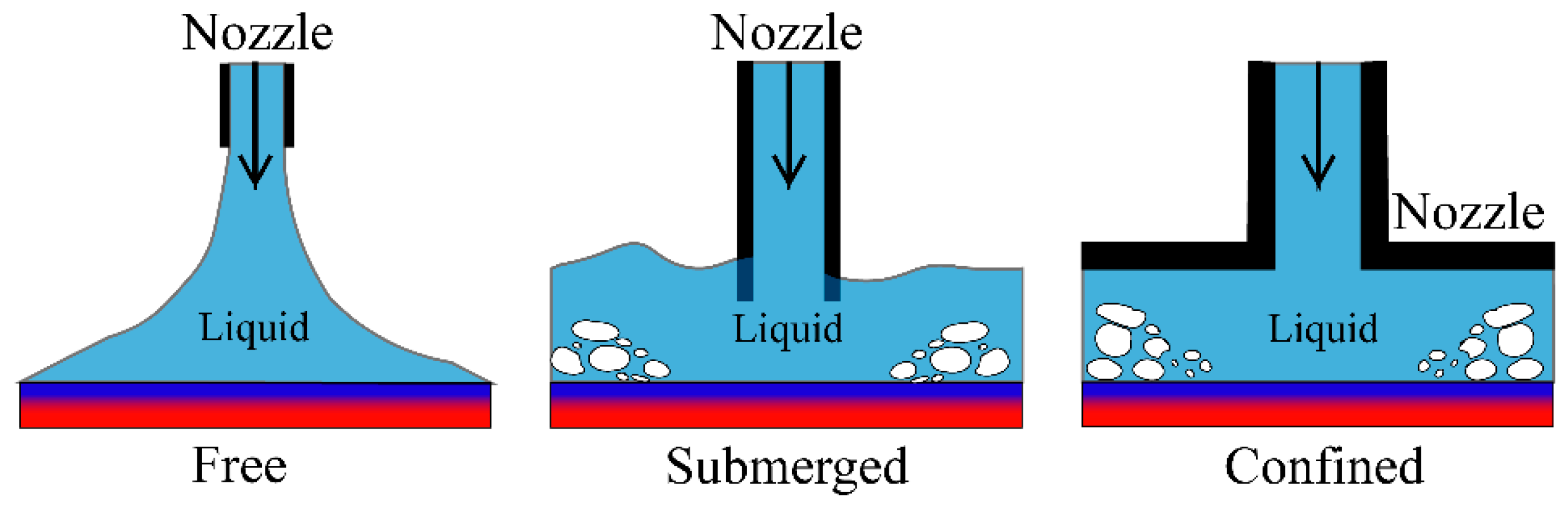
2.2.2. Spray Cooling and Jet Impingement
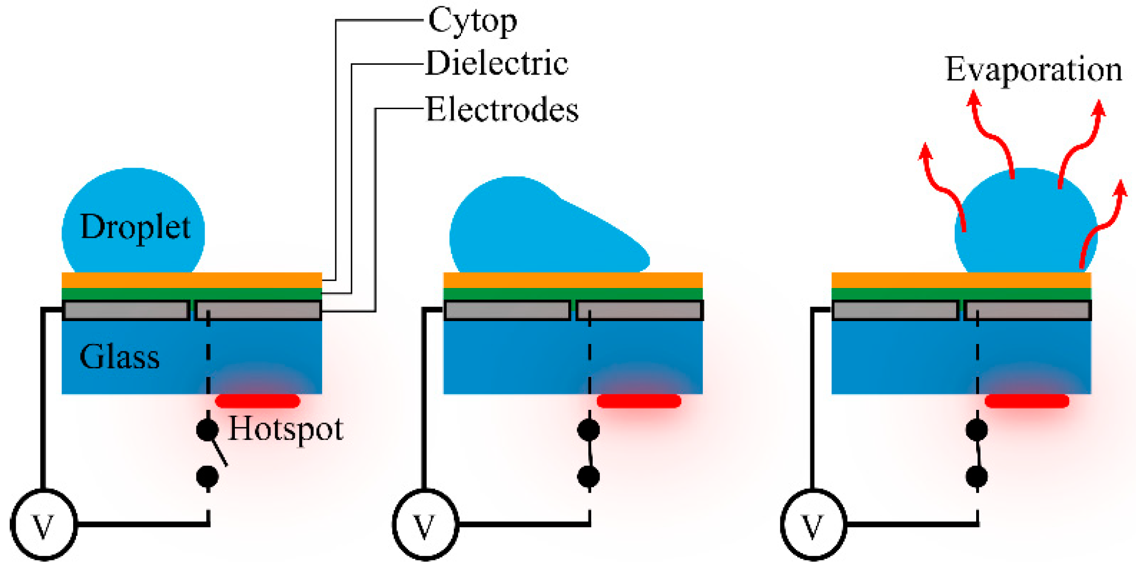
2.2.3. Droplet Electrowetting
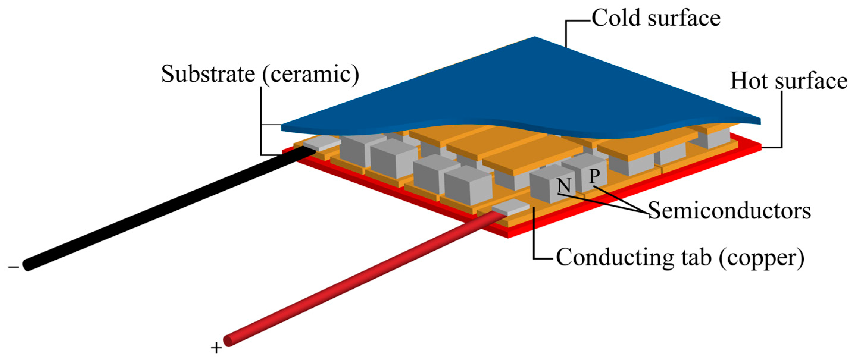
2.2.4. Thermoelectric Cooling
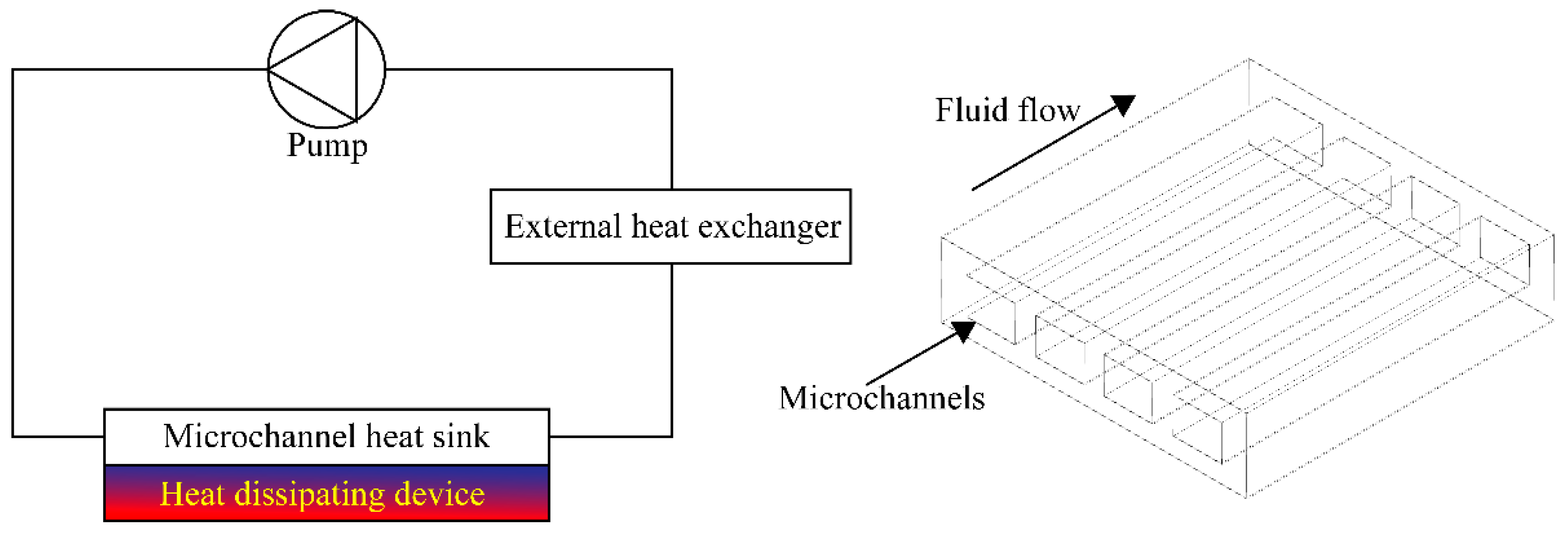
2.2.5. Microchannel Heat Sinks
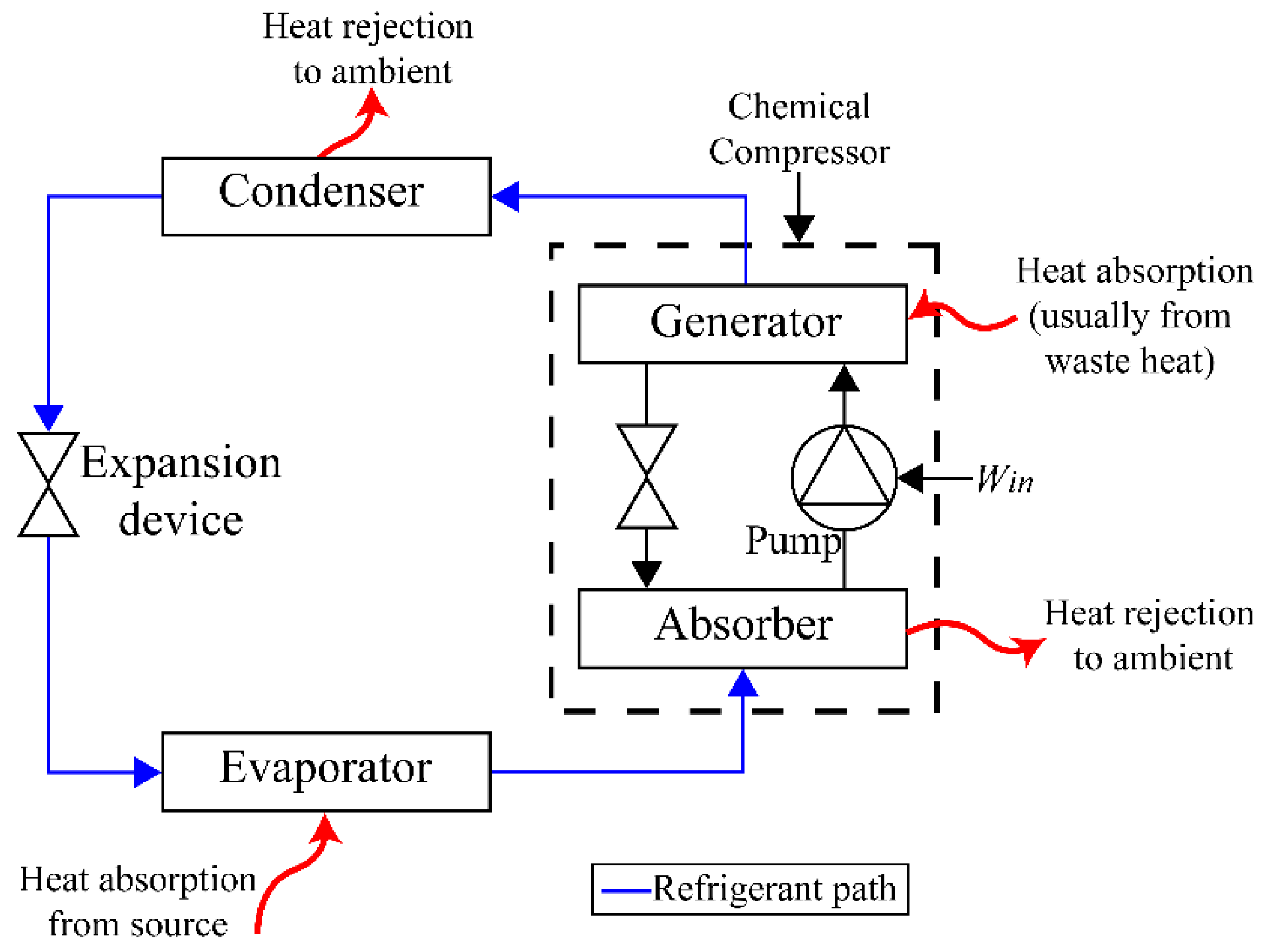
2.2.6. Absorption Cooling
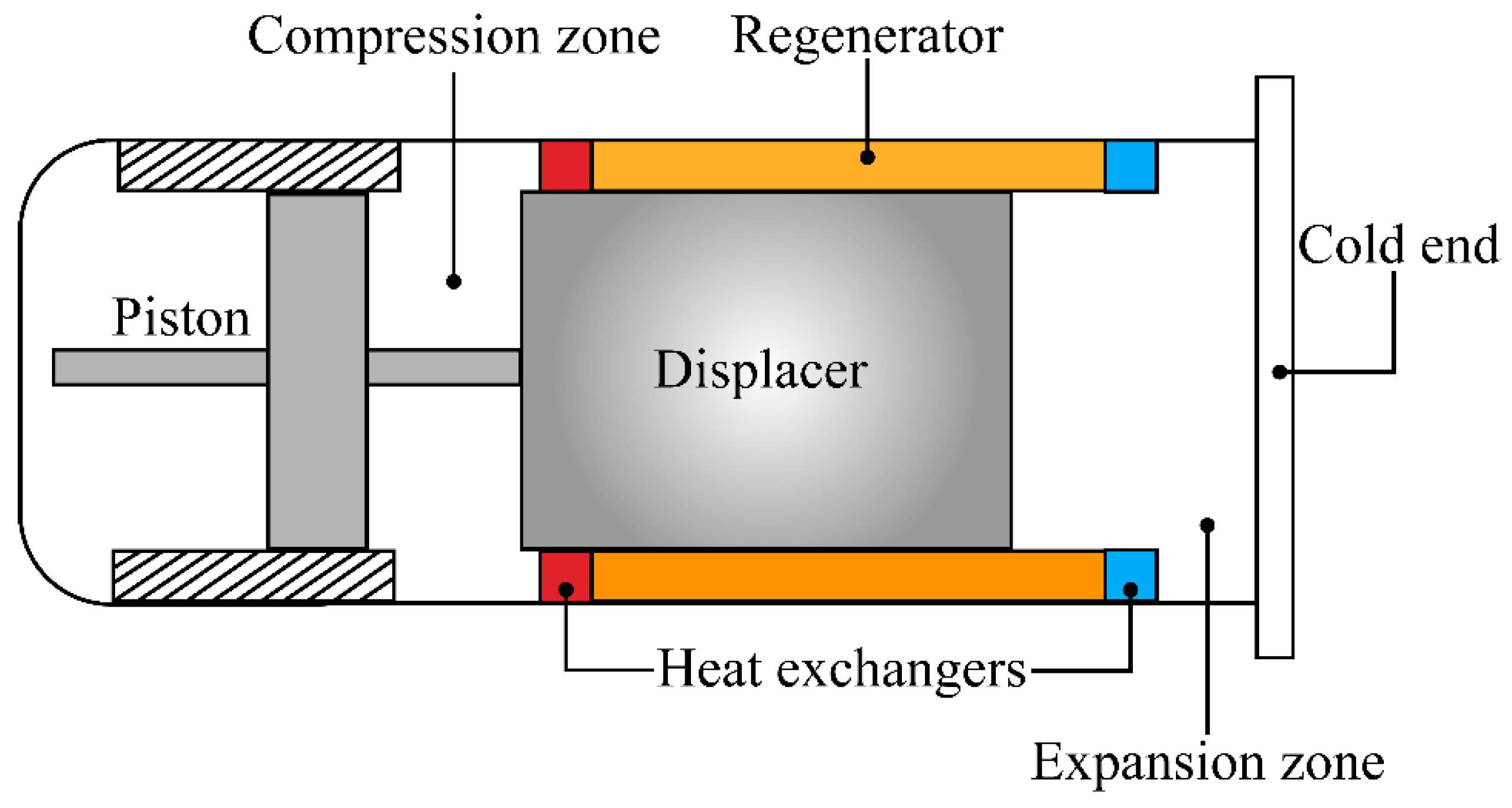
2.2.7. Stirling Cooling
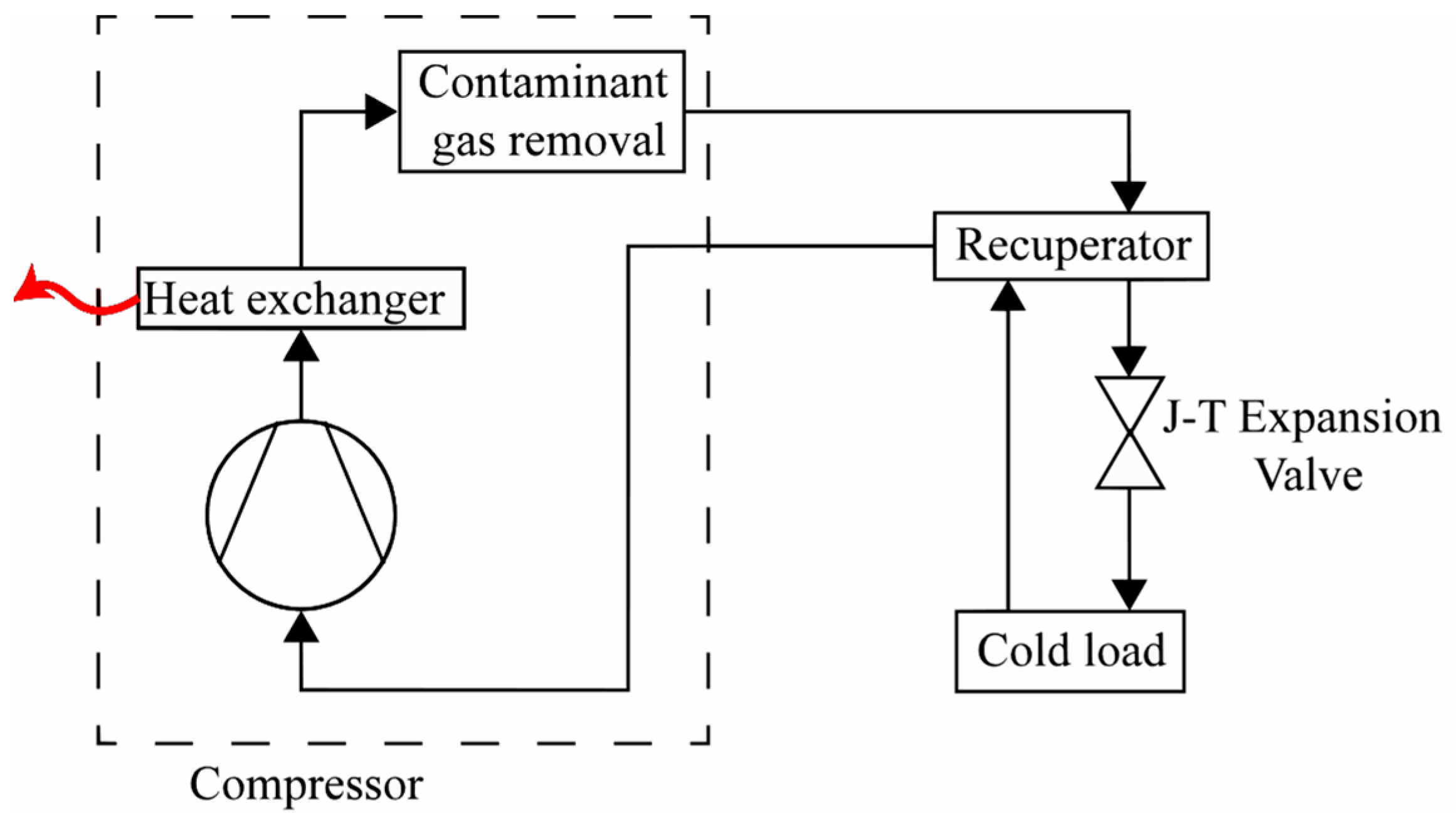
2.2.8. Joule–Thomson (J-T) Cooling
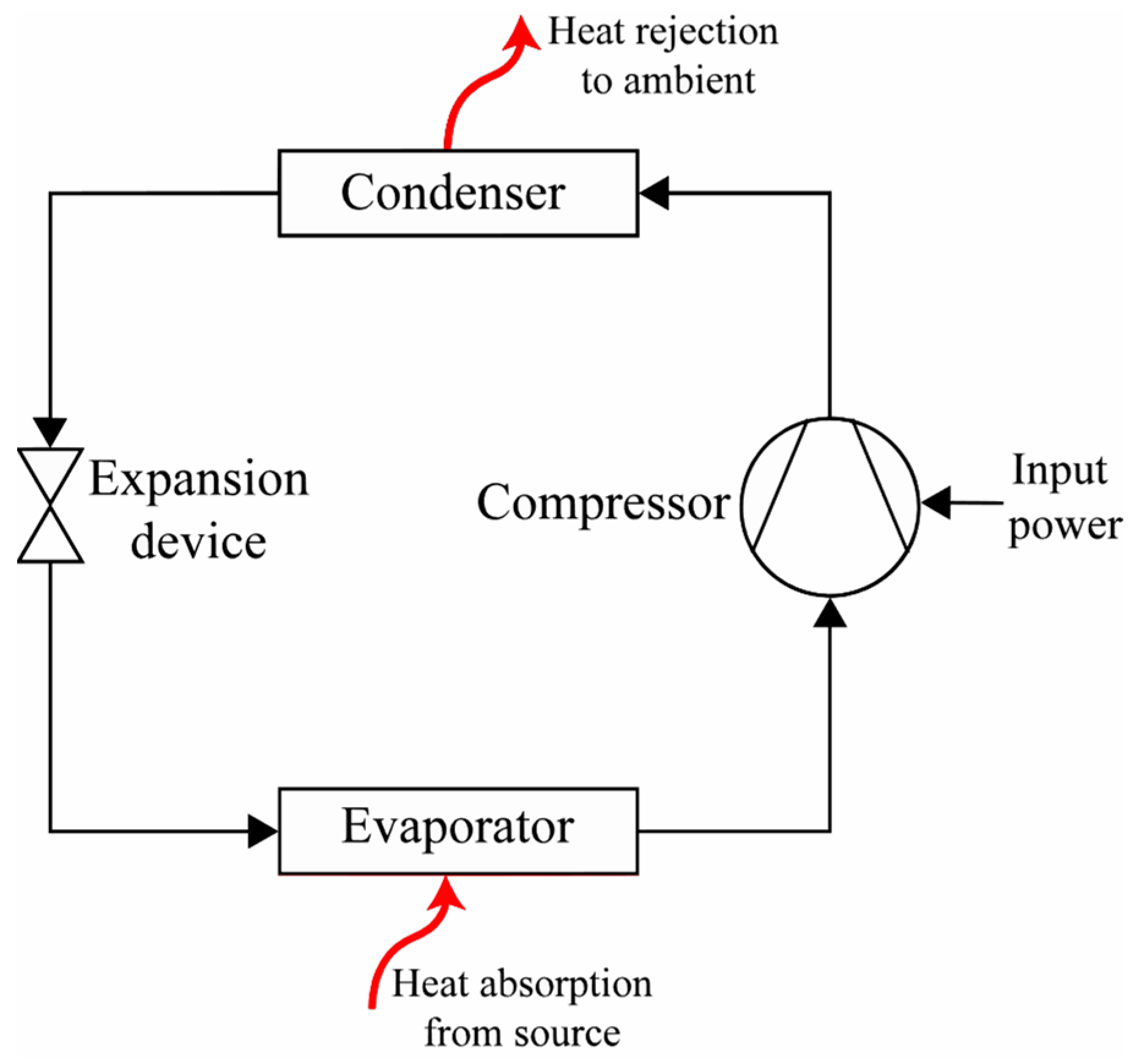
2.2.9. VCR Systems
3. Small-Scale Vapor Compression Refrigeration (VCR) Systems
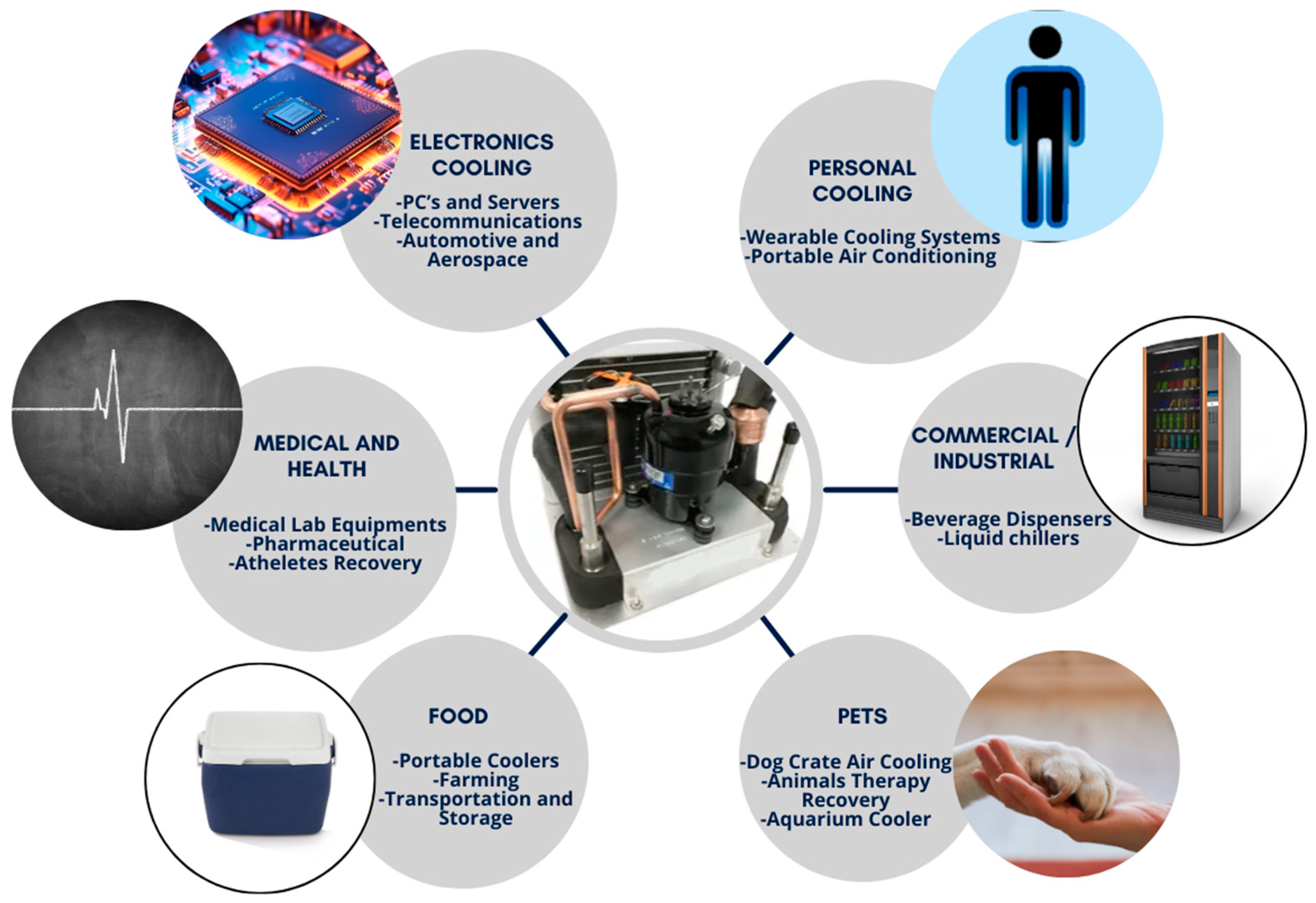
3.1. Small-Scale Vapor Compression Applications
3.1.1. Electronics Cooling
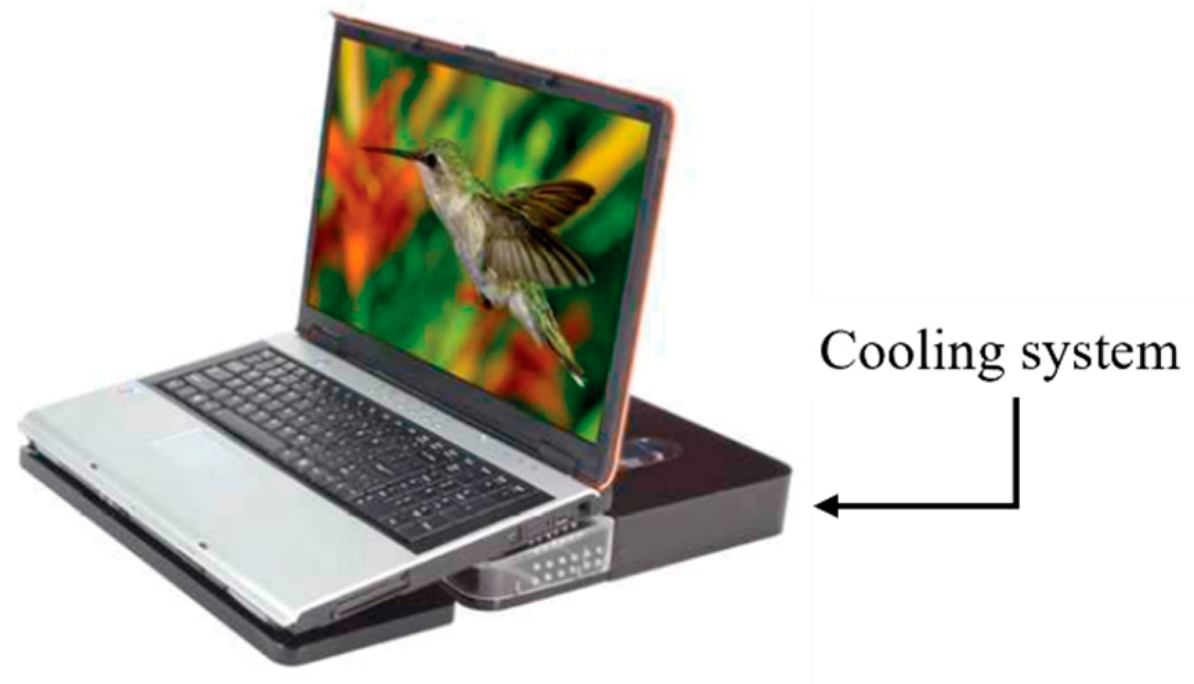
3.1.2. Personal Cooling
3.2. Modifications to the Basic Vapor Compression Cycle
3.3. Modeling
3.4. Components
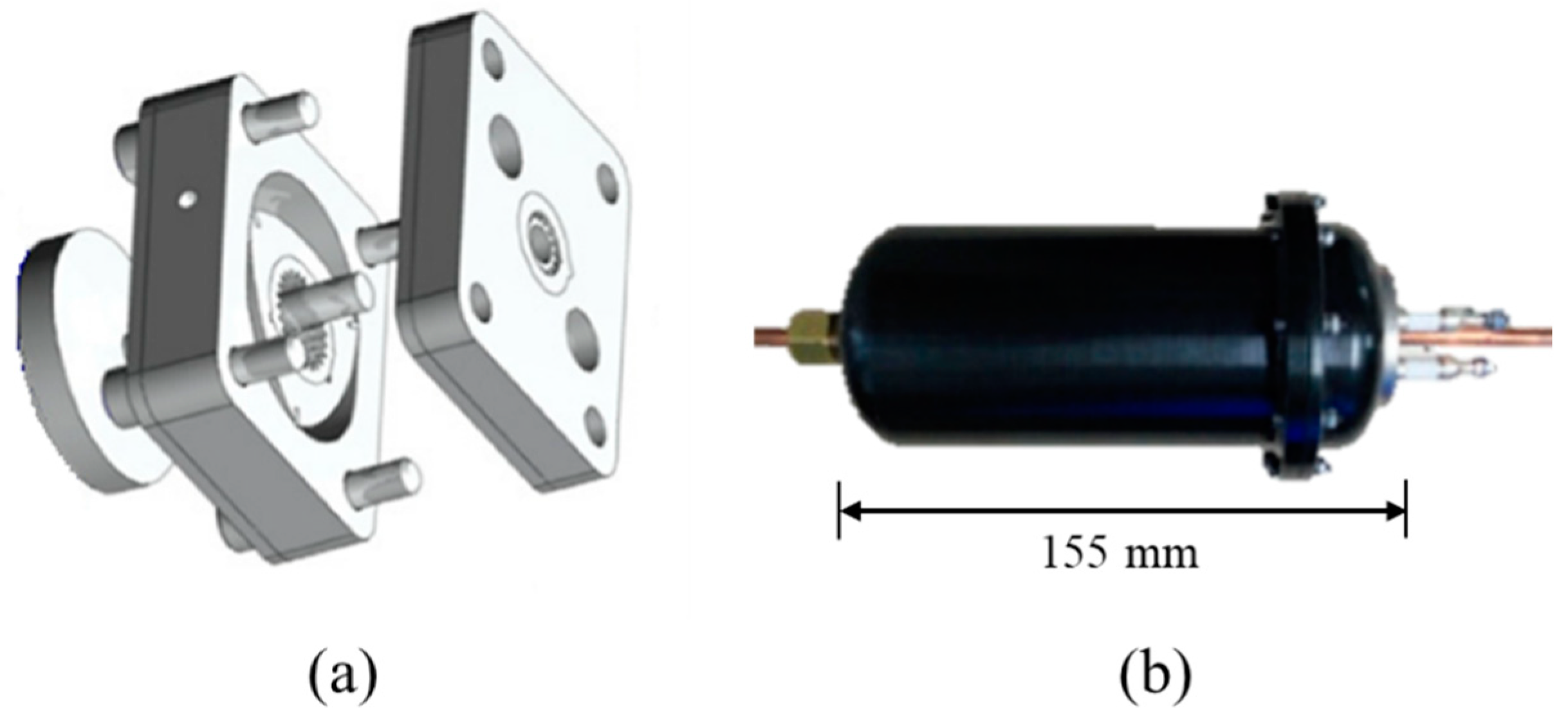
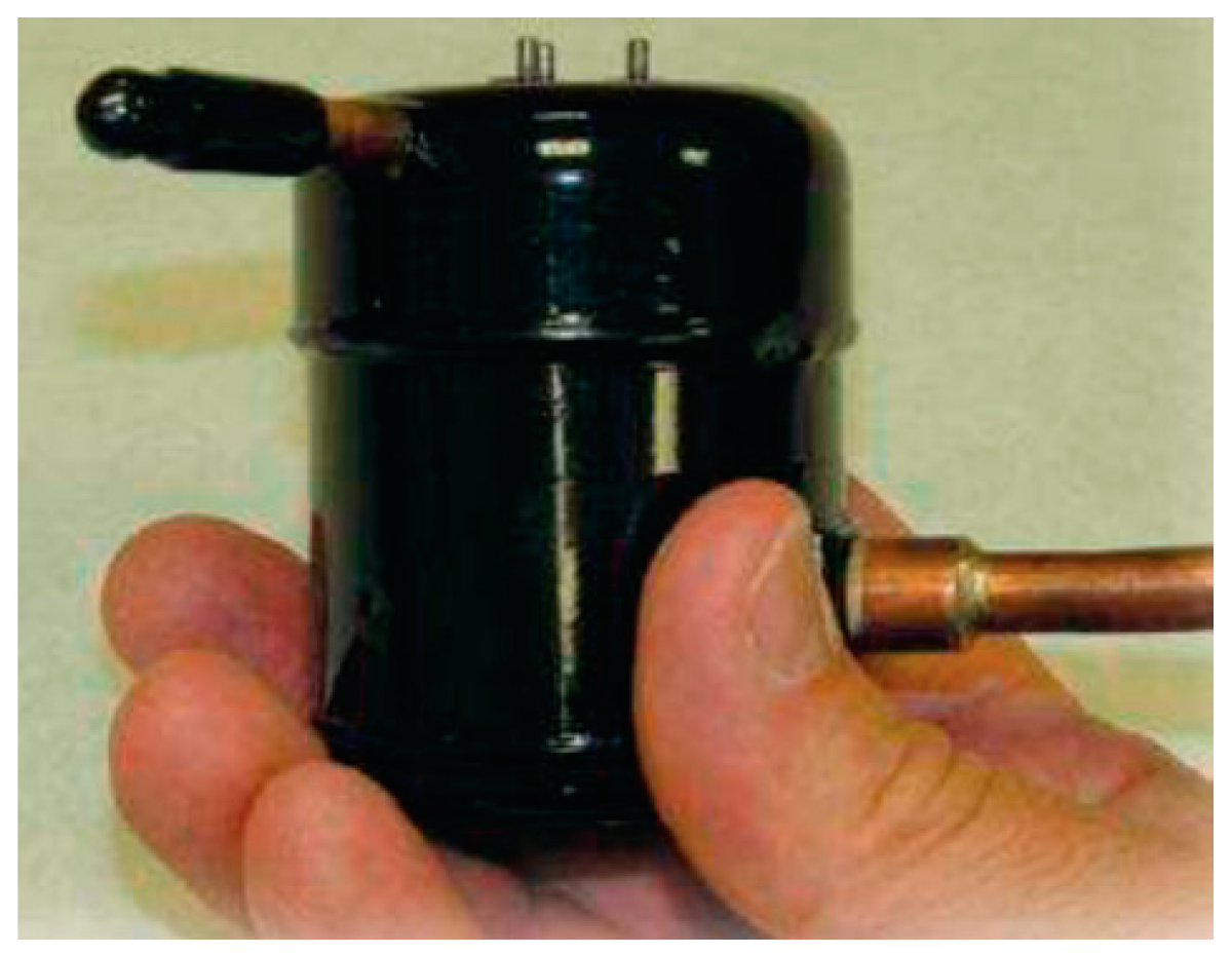
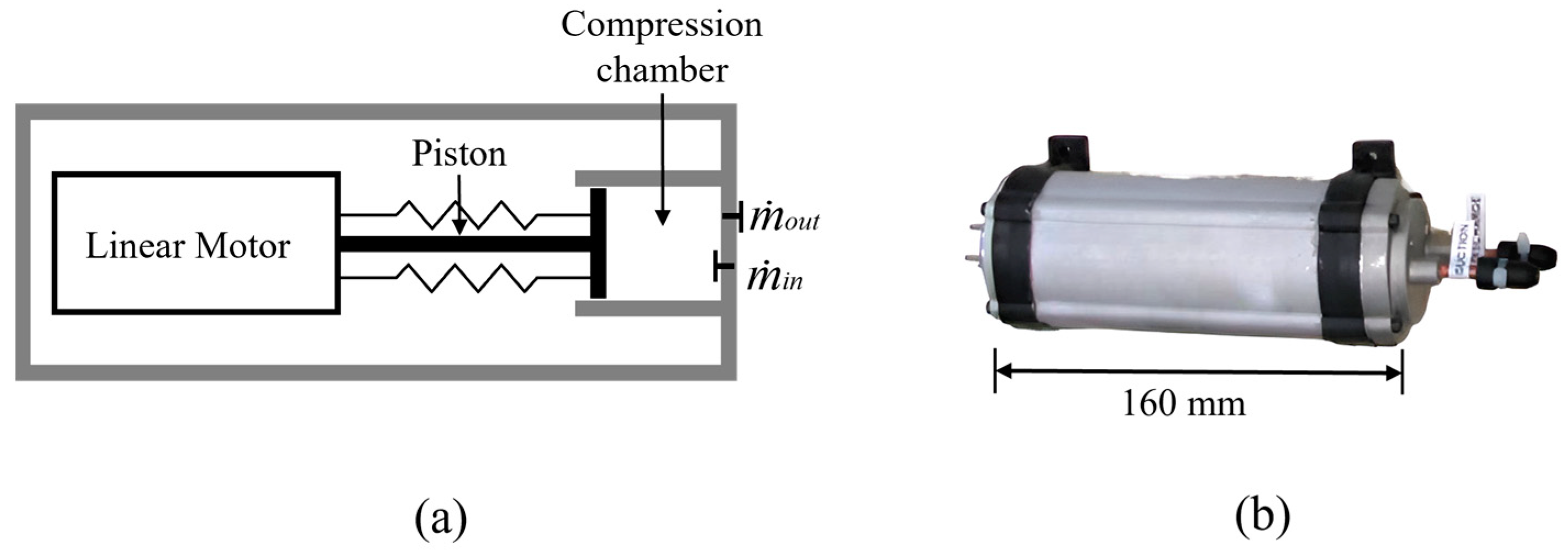
3.4.1. Compressors
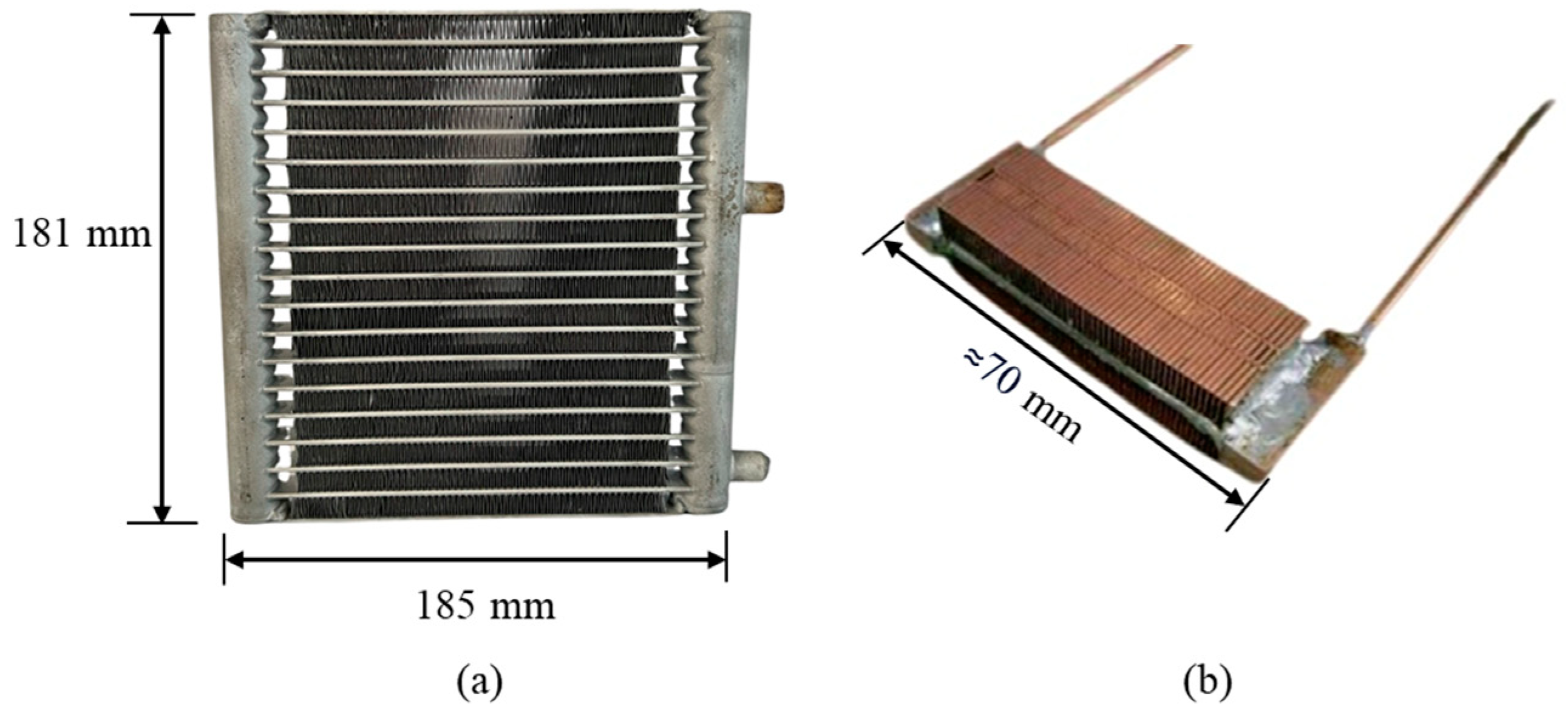
3.4.2. Condensers
3.4.3. Expansion Devices
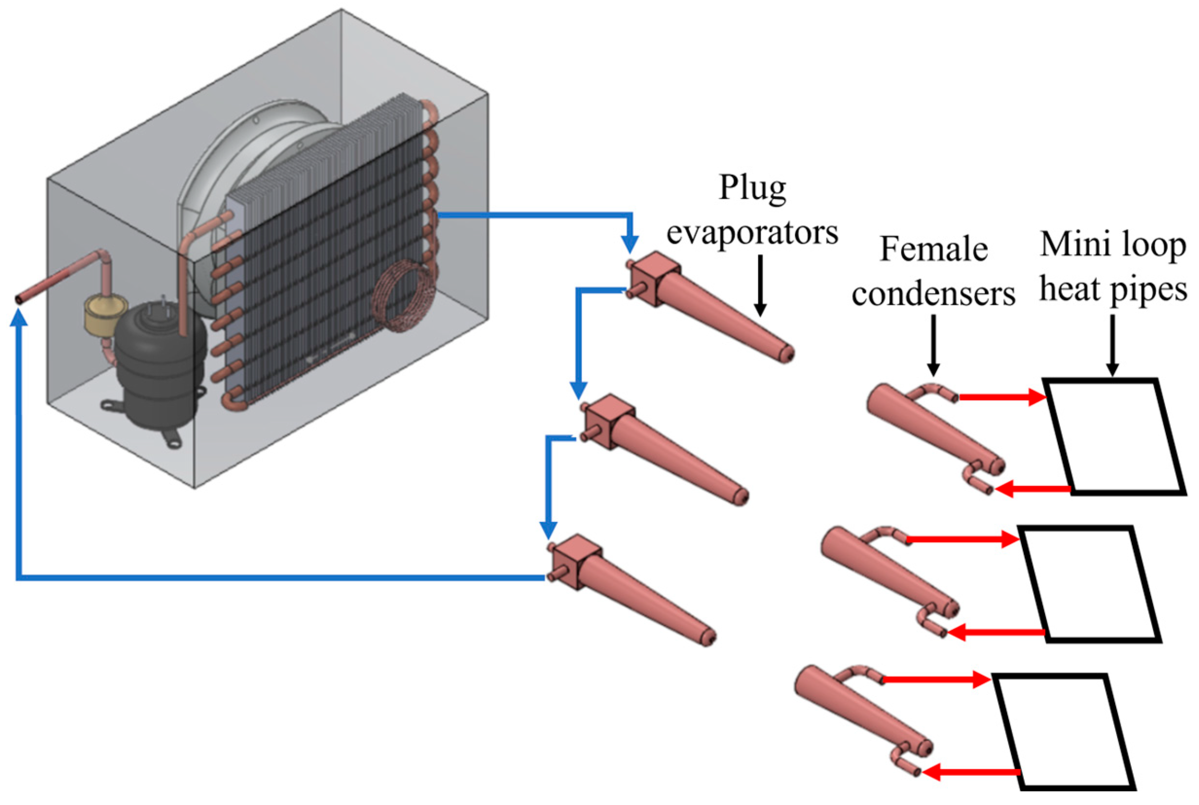
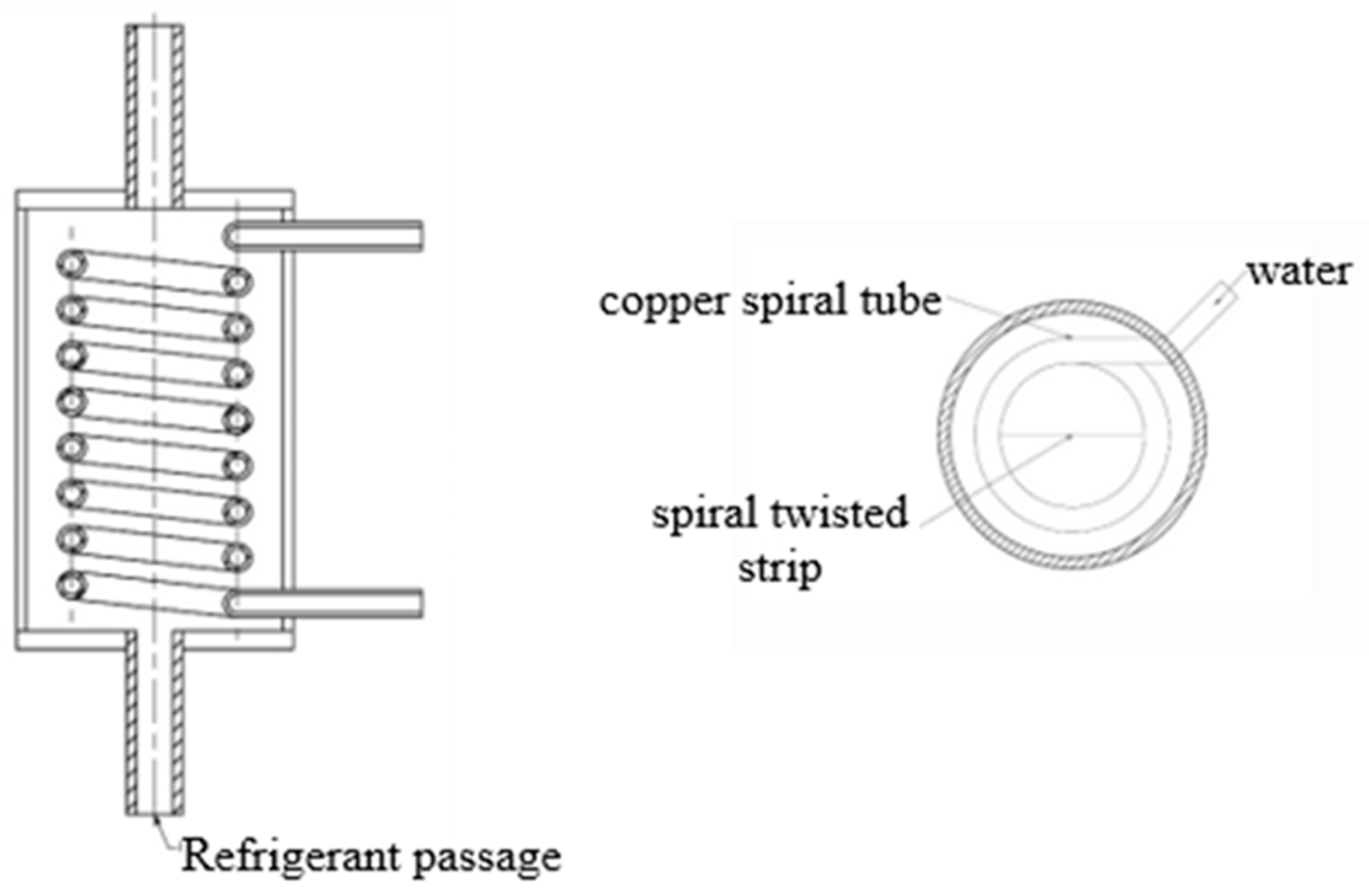
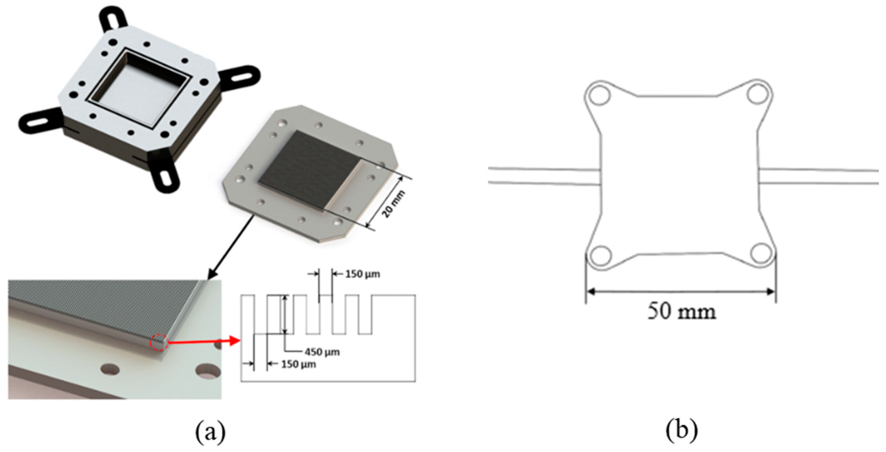
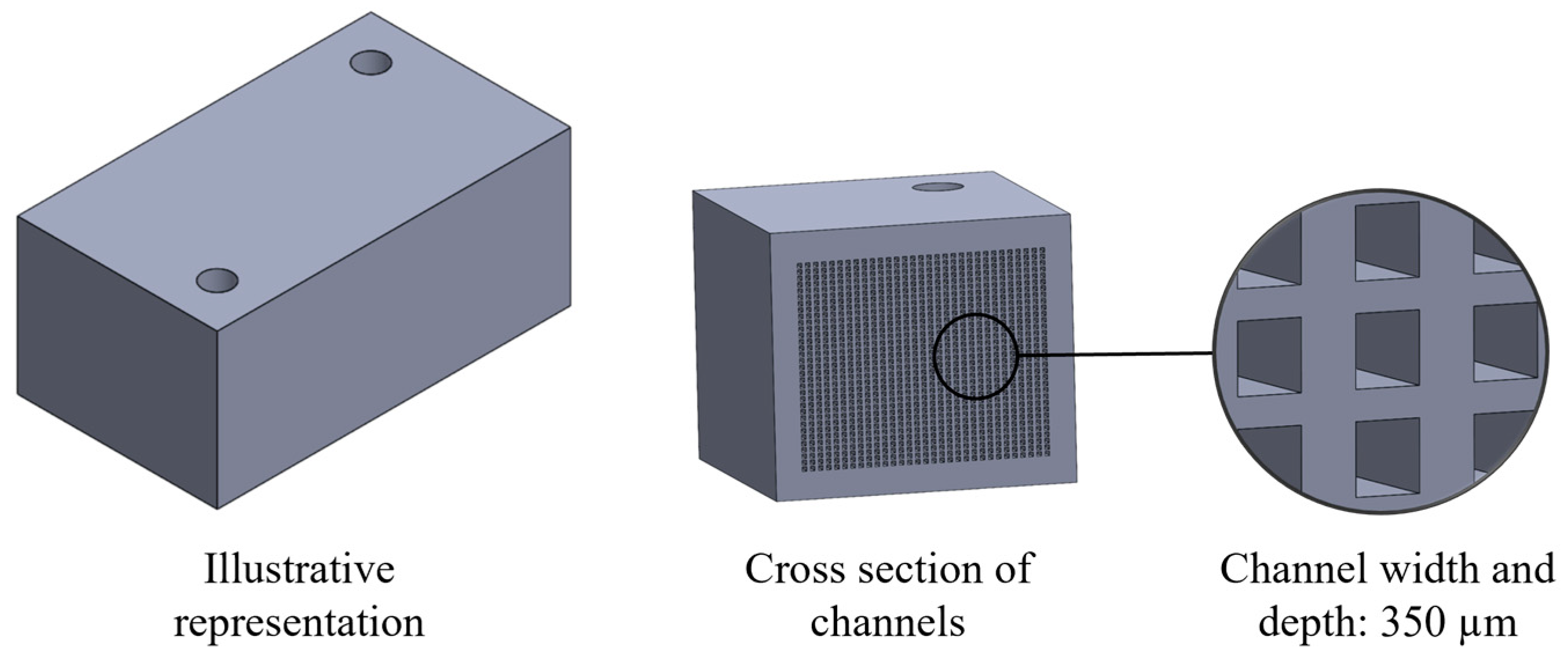
3.4.4. Evaporators
4. Challenges, Perspectives, and Future Directions on Small-Scale Refrigeration
- Electronics and information technology: the manufacture of electronic devices such as computers, servers, microprocessors, and similar components demands precise temperature control for maintaining performance and reliability, as mentioned in Section 3.
- Pharmaceutical and food industry: these systems can be essential to ensure the quality and safety of pharmaceutical and food products, especially those that require storage and transport at controlled temperatures.
- Automotive and aerospace sector: in the cooling of electronic systems on board vehicles and aircraft, as well as in the thermal management of critical components, miniature systems can be beneficial due to space and weight limitations.
- Medical sector: in portable or small-sized medical devices, such as portable diagnostic devices, medical imaging systems, or cooling equipment for biological samples, these systems may be necessary to ensure proper operation and accuracy of the devices.
- Commercial constraints: while major suppliers of these systems maintain an internationally accessible online market, the absence of brick-and-mortar stores and the need to accommodate delivery times pose a limitation directly affecting the affordability of the products.
- Technical constraints: given the limited availability of these systems, technicians providing services may have limited experience installing, operating, and maintaining such technology.
- Regulations and standards: in industries such as pharmaceutical and food, refrigeration systems must comply with strict regulations and standards to ensure product safety and quality. Ensuring compliance with these regulations can be a major constraint in the design and implementation of miniature refrigeration systems.
- Technological constraints: from a technological standpoint, numerous areas of opportunity exist for further enhancements in these systems, as outlined below in the context of future trends.
5. Concluding Remarks
- Miniature vapor compression refrigeration appears to be the best option for many small-scale cooling applications due to advantages such as working over a wide range of operating temperatures, ability to cool down junction temperature below ambient, potential for high COP values, operation for long periods at large cooling capacity with low mass flow rates, and transport of heat away from its source. In addition, vapor compression is well suited for portable applications compared to alternative technologies that involve greater number of components and complexity.
- In the past decade, there has been a reduction in the number of research papers published on miniature vapor compression refrigeration research primarily directed toward cooling electronic components and personal cooling. However, alternative applications are currently being commercially offered in sectors such as medical, pharmaceutical, automotive, and food preservation, among others. Consequently, further research is necessary to validate their feasibility for both existing and prospective applications, facilitating widespread commercialization.
- It can be concluded that the challenges associated with component miniaturization have been a critical factor hindering widespread study and development of these systems. Many of the components used in the publications cited in this review were custom-built by researchers due to limited commercial availability, thus slowing technical progress. It is, however, anticipated that research will experience a resurgence in the coming years, given the current availability of both individual components and pre-assembled prototypes of miniature VCR systems in the market.
- The industrial sector has a strong need for effective thermal management and heat dissipation, while commercial, technical, technological, and normative aspects limit the applicability of small-scale refrigeration.
- It is finally observed that miniature vapor compression refrigeration has not reached maturity since there are still many areas to be explored, including, among others, evaluation of low GWP refrigerants, search for energy savings, improvements in energy efficiency, additive manufacturing, artificial intelligence, and integration with renewable energies. Some of these topics have been addressed for conventional refrigerators and now demand further development for application to miniature systems.
Author Contributions
Funding
Institutional Review Board Statement
Informed Consent Statement
Data Availability Statement
Acknowledgments
Conflicts of Interest
Nomenclature
| h | Enthalpy |
| ṁ | Mass flow rate |
| N | Compressor rotation speed |
| P | Pressure |
| Q | Heat rejected/absorbed |
| T | Temperature |
| W | Input power |
| η | Efficiency |
| Abbreviations | |
| BJ | Box–Jenkins |
| CC | Cooling Capacity |
| cc | Cubic Centimeters |
| COP | Coefficient of Performance |
| CPU | Central Processing Unit |
| DC | Direct Current |
| EES | Engineering Equation Solver |
| EER Energy | Efficiency Ratio |
| EWOD | Electro-Wetting on Dielectric |
| GWP | Global Warming Potential |
| HVAC&R | Heating, Ventilation, Air Conditioning, and Refrigeration |
| ITRS | International Technology Roadmap for Semiconductors |
| MIMO | Multi-Input Multi-Output |
| NSGA-II | Nondominated Storing Genetic Algorithm II |
| OMOPSO | Multi-Objective Particle Swarm Optimization |
| PCM | Phase Change Material |
| PECS | Personalized Environmental Control Systems |
| PTMS | Personal Thermal Management Systems |
| rpm | Revolutions Per Minute |
| TAC | Task Ambient Conditioning |
| VCR | Vapor Compression Refrigeration |
| Subscripts | |
| comp | compressor |
| cond | condenser |
| evap | evaporator |
| ref | refrigerant |
References
- International Institute of Refrigeration. 38th Informatory Note on Refrigeration Technologies. The Role of Refrigeration in the Global Economy; IIR: Paris, France, 2019; Available online: https://iifiir.org/en/fridoc/the-role-of-refrigeration-in-the-global-economy-2019-142028 (accessed on 10 April 2022).
- UNEP. Amendment to the Montreal Protocol on Substances that Deplete the Ozone Layer; United Nations Environment Programme: Kigali, Rwanda, 2016; Available online: https://ozone.unep.org (accessed on 23 November 2022).
- International Institute of Refrigeration. 48th Informatory Note on Refrigeration Technologies. Low-GWP Refrigerants: Status and Outlook; IIR: Paris, France, 2022; Available online: https://iifiir.org/en/fridoc/low-gwp-refrigerants-status-and-outlook-48-lt-sup-gt-th-lt-sup-gt-informatory-145388 (accessed on 8 June 2023).
- Geetha, N.B.; Velraj, R. Passive cooling methods for energy efficient buildings with and without thermal energy storage—A review. Energy Educ. Sci. Technol. Part A Energy Sci. Res. 2012, 29, 913–946. [Google Scholar]
- Zhang, Z.; Wang, X.; Yan, Y. A review of the state-of-the-art in electronic cooling. E-Prime-Adv. Electr. Eng. Electron. Energy 2021, 1, 100009. [Google Scholar] [CrossRef]
- Cao, J.; Zheng, Z.; Asim, M.; Hu, M.; Wang, Q.; Su, Y.; Pei, G.; Leung, M.K.H. A review on independent and integrated/coupled two-phase loop thermosyphons. Appl. Energy 2020, 280, 115885. [Google Scholar] [CrossRef]
- He, Z.; Yan, Y.; Zhang, Z. Thermal management and temperature uniformity enhancement of electronic devices by micro heat sinks: A review. Energy 2021, 216, 119223. [Google Scholar] [CrossRef]
- Yeom, J.; Shannon, M.A.; Singh, T. Micro-Coolers. In Reference Module in Materials Science and Materials; Elsevier: Amsterdam, The Netherlands, 2017. [Google Scholar]
- Barbosa, J.R., Jr. Recent developments in vapor compression technologies for small scale refrigeration applications. In Proceedings of the ASME 2011 9th International Conference on Nanochannels, Microchannels and Minichannels (ASME-ICNMM2011), Edmonton, AB, Canada, 19–22 June 2011. [Google Scholar] [CrossRef]
- Barbosa, J.R., Jr.; Ribeiro, G.B.; De Oliveira, P.A. A state-of-the-art review of compact vapor compression refrigeration systems and their applications. Heat. Transf. Eng. 2012, 33, 356–374. [Google Scholar] [CrossRef]
- Aspen Compressor, LLC. Available online: https://www.aspencompressor.com/applications (accessed on 10 October 2022).
- RIGID HVAC CO., LTD. Available online: https://www.rigidhvac.com/applications (accessed on 10 February 2023).
- Türkakar, G.; Okutucu-Özyurt, T.; Kandlikar, S.G. Entropy generation analysis of a microchannel-condenser for use in a vapor compression refrigeration cycle. Int. J. Refrig. 2016, 70, 71–83. [Google Scholar] [CrossRef]
- Wu, Z.; Du, R. Design and experimental study of a miniature vapor compression refrigeration system for electronics cooling. Appl. Therm. Eng. 2011, 31, 385–390. [Google Scholar] [CrossRef]
- Phelan, P.E.; Chiriac, V.A.; Lee, T.-Y.T. Current and future miniature refrigeration cooling technologies for high power microelectronics. IEEE Trans. Compon. Packag. Technol. 2002, 25, 356–365. [Google Scholar] [CrossRef]
- Warren, W.L.; Dubois, L.H.; Wax, S.G.; Gardos, M.N.; Fehrenbacher, L.L. Mesoscale machines and electronics: “there’s plenty of room in the middle”. In Proceedings of the ASME 1999 International Mechanical Engineering Congress and Exposition, Nashville, TN, USA, 14–19 November 1999. [Google Scholar]
- Rahimi, A.; Dehghan Saee, A.; Kasaeipoor, A.; Hasani Malekshah, E. A comprehensive review on natural convection flow and heat transfer: The most practical geometries for engineering applications. Int. J. Numer. Methods Heat. Fluid. Flow. 2019, 29, 834–877. [Google Scholar] [CrossRef]
- Chen, X.; Ye, H.; Fan, X.; Ren, T.; Zhang, G. A review of small heat pipes for electronics. Appl. Therm. Eng. 2016, 96, 1–17. [Google Scholar] [CrossRef]
- Huang, G.; Liu, W.; Luo, Y.; Li, Y.; Chen, H. A new ultra-thin vapor chamber with composite wick for thin electronic products. Int. J. Therm. Sci. 2021, 170, 107145. [Google Scholar] [CrossRef]
- Ding, T.; Chen, X.; Cao, H.; He, Z.; Wang, J.; Li, Z. Principles of loop thermosyphon and its application in data center cooling systems: A review. Renew. Sustain. Energy Rev. 2021, 150, 111389. [Google Scholar] [CrossRef]
- Joo, Y.; Kim, S.J. Comparison of thermal performance between plate-fin and pin-fin heat sinks in natural convection. Int. J. Heat. Mass. Transf. 2015, 83, 345–356. [Google Scholar] [CrossRef]
- Pambudi, N.A.; Sarifudin, A.; Firdaus, R.A.; Ulfa, D.K.; Gandidi, I.M.; Romadhon, R. The immersion cooling technology: Current and future development in energy saving. Alex. Eng. J. 2022, 61, 9509–9527. [Google Scholar] [CrossRef]
- Ling, Z.; Zhang, Z.; Shi, G.; Fang, X.; Wang, L.; Gao, X.; Fang, Y.; Xu, T.; Wang, S.; Liu, X. Review on thermal management systems using phase change materials for electronic components, Li-ion batteries and photovoltaic modules. Renew. Sustain. Energy Rev. 2014, 31, 427–438. [Google Scholar] [CrossRef]
- Khattak, Z.; Ali, H.M. Air cooled heat sink geometries subject to forced flow: A critical review. Int. J. Heat. Mass. Transf. 2019, 130, 141–161. [Google Scholar] [CrossRef]
- Behi, H.; Behi, M.; Karimi, D.; Jaguemont, J.; Ghanbarpour, M.; Behnia, M.; Berecibar, M.; Van Mierlo, J. Heat pipe air-cooled thermal management system for lithium-ion batteries: High power application. Appl. Therm. Eng. 2021, 183, 116240. [Google Scholar] [CrossRef]
- Afshari, F. Experimental and numerical investigation on thermoelectric coolers for comparing air-to-water to air-to-air refrigerators. J. Therm. Anal. Calorim. 2021, 144, 855–868. [Google Scholar] [CrossRef]
- Murshed, S.S.; De Castro, C.N. A critical review of traditional and emerging techniques and fluids for electronics cooling. Renew. Sustain. Energy Rev. 2017, 78, 821–833. [Google Scholar] [CrossRef]
- Cheng, W.-L.; Zhang, W.-W.; Chen, H.; Hu, L. Spray cooling and flash evaporation cooling: The current development and application. Renew. Sustain. Energy Rev. 2016, 55, 614–628. [Google Scholar] [CrossRef]
- Kumar Tyagi, P.; Kumar, R.; Kumar Mondal, P. A review of the state-of-the-art nanofluid spray and jet impingement cooling. Phys. Fluids 2020, 32, 121301. [Google Scholar] [CrossRef]
- Sharma, R.K.; Bash, C.E.; Patel, C.D. Inkjet Assisted Micro-scale cooling of Electronics. Enabling device compaction by efficient thermal management. NSTI Nanotech 2005, 1, 644–647. Available online: https://briefs.techconnect.org/wp-content/volumes/Nanotech2005v1/pdf/529.pdf (accessed on 27 November 2022).
- Butterfield, D.J.; Iverson, B.D.; Maynes, D.; Crockett, J. Transient heat transfer of impinging jets on superheated wetting and non-wetting surfaces. Int. J. Heat. Mass. Transf. 2021, 175, 121056. [Google Scholar] [CrossRef]
- Ahmad, I.; Ranjan, A.; Pathak, M.; Khan, M.K. A Wettability-Mediated Microdroplet under Electrowetting Effect for Hotspot Cooling. IEEE Trans. Compon. Packag. Manuf. Technol. 2022, 12, 288–296. [Google Scholar] [CrossRef]
- Yan, Z.; Jin, M.; Li, Z.; Zhou, G.; Shui, L. Droplet-Based Microfluidic Thermal Management Methods for High Performance Electronic Devices. Micromachines 2019, 10, 89. [Google Scholar] [CrossRef] [PubMed]
- Salah, W.A.; Abuhelwa, M. Review of thermoelectric cooling devices recent applications. J. Eng. Sci. Technol. 2020, 15, 455–476. [Google Scholar]
- Sahu, V.; Fedorov, A.G.; Joshi, Y.; Yazawa, K.; Ziabari, A.; Shakouri, A. Energy Efficient Liquid-Thermoelectric Hybrid Cooling for Hot-Spot Removal. In Proceedings of the 28th Annual IEEE Semiconductor Thermal Measurement and Management Symposium, San Jose, CA, USA, 18–22 March 2012; Available online: https://www.academia.edu/83725635/Energy_efficient_liquid_thermoelectric_hybrid_cooling_for_hot_spot_removal (accessed on 2 December 2022).
- Hassan, I.; Phutthavong, P.; Abdelgawad, M. Microchannel heat sinks: An overview of the state-of-the-art. Nanoscale Microscale Thermophys. Eng. 2004, 8, 183–205. [Google Scholar] [CrossRef]
- Zhou, J.; Cao, X.; Zhang, N.; Yuan, Y.; Zhao, X.; Hardy, D. Micro-Channel heat sink: A review. J. Therm. Sci. 2020, 29, 1431–1462. [Google Scholar] [CrossRef]
- Determan, M.D.; Garimella, S. Design, fabrication, and experimental demonstration of a microscale monolithic modular absorption heat pump. Appl. Therm. Eng. 2012, 47, 119–125. [Google Scholar] [CrossRef]
- Doğan, B.; Ozturk, M.M.; Erbay, L.B. Effect of working fluid on the performance of the duplex Stirling refrigerator. J. Clean. Prod. 2018, 189, 98–107. [Google Scholar] [CrossRef]
- Xu, Y.; Sun, D.; Qiao, X.; Yu, Y.S.W.; Zhang, N.; Zhang, J.; Cai, Y. Operating characteristics of a single-stage Stirling cryocooler capable of providing 700W cooling power at 77K. Cryogenics 2017, 83, 78–84. [Google Scholar] [CrossRef]
- Chakravarthy, V.S.; Shah, R.K.; Venkatarathnam, G. A Review of Refrigeration Methods in the Temperature Range 4-300 K. ASME. J. Therm. Sci. Eng. Appl. 2011, 3, 020801. [Google Scholar] [CrossRef]
- Liang, K.; Li, Z.; Chen, M.; Jiang, H. Comparisons between heat pipe, thermoelectric system, and vapour compression refrigeration system for electronics cooling. Appl. Therm. Eng. 2018, 146, 260–267. [Google Scholar] [CrossRef]
- Peeples, J.W. Vapor compression cooling for high performance applications. Electron. Cool. 2001, 7, 16–25. [Google Scholar]
- Schmidt, R.R.; Notohardjono, B.D. High-end server low-temperature cooling. IBM J. Res. Dev. 2002, 46, 739–751. [Google Scholar] [CrossRef]
- Shalf, J. The future of computing beyond Moore’s Law. Phil. Trans. R. Soc. A 2020, 378, 20190061. [Google Scholar] [CrossRef] [PubMed]
- Poachaiyapoom, A.; Leardkun, R.; Mounkong, J.; Wongwises, S. Miniature vapor compression refrigeration system for electronics cooling. Case Stud. Therm. Eng. 2019, 13, 100365. [Google Scholar] [CrossRef]
- Yang, J.J.; Li, K.; Cui, X.Y. Experimental study on miniature-refrigeration system. Key Eng. Mat. 2012, 531–532, 584–587. [Google Scholar] [CrossRef]
- Trutassanawin, S.; Groll, E.A.; Garimella, S.V.; Cremaschi, L. Experimental Investigation of a Miniature-Scale Refrigeration System for Electronics Cooling. IEEE Trans. Compon. Packag. Technol. 2006, 29, 678–687. [Google Scholar] [CrossRef]
- Trutassanawin, S.; Groll, E.A. Numerical Analysis of a Miniature-Scale Refrigeration System (MSRS) for Electronics Cooling. In Proceedings of the 10th International Refrigeration and Air Conditioning Conference at Purdue, West Lafayette, IN, USA, 12–15 July 2004; Available online: https://docs.lib.purdue.edu/iracc/679/ (accessed on 8 July 2022).
- Mongia, R.; Masahiro, K.; DiStefano, E.; Barry, J.; Chen, W.B.; Izenson, M.; Possamai, F.; Zimmermann, A.; Mochizuki, M. Small scale refrigeration system for electronics cooling within a notebook computer. In Proceedings of the Thermal and Thermomechanical Proceedings 10th Intersociety Conference on Phenomena in Electronics Systems (ITHERM’06), San Diego, CA, USA, 30 May–2 June 2006. [Google Scholar] [CrossRef]
- Possamai, F.; Lilie, D.E.B.; Zimmermann, A.J.P.; Mongia, R. Miniature Vapor Compression System. In Proceedings of the 12th International Refrigeration and Air Conditioning Conference at Purdue, West Lafayette, IN, USA, 14–17 July 2012; Available online: https://docs.lib.purdue.edu/iracc/963/ (accessed on 7 August 2022).
- Melo, C.; Ferreira, R.T.S.; Boabaid Neto, C.; Gonçalves, J.M.; Mezavila, M.M. An experimental analysis of adiabatic capillary tubes. Appl. Therm. Eng. 1999, 19, 669–684. [Google Scholar] [CrossRef]
- Ribeiro, G.B. Development and Analysis of a Compact Cooling System Using the Microcompressor. In Proceedings of the 13th InterSociety Conference on Thermal and Thermomechanical Phenomena in Electronic Systems, San Diego, CA, USA, 30 May–1 June 2012. [Google Scholar] [CrossRef]
- Ribeiro, G.B. Development of a High Ambient Temperature Cooling Unit Based on Microcompressor Technology. In Proceedings of the 14th International Refrigeration and Air Conditioning Conference at Purdue, West Lafayette, IN, USA, 16–19 July 2012; Available online: https://docs.lib.purdue.edu/iracc/1225/ (accessed on 30 July 2022).
- Mancin, S.; Zilio, C.; Righetti, G.; Rossetto, L. Mini Vapor Cycle System for high density electronic cooling applications. Int. J. Refrig. 2013, 36, 1191–1202. [Google Scholar] [CrossRef]
- Zilio, C.; Righetti, G.; Mancin, S.; Hodot, R.; Sarno, C.; Pomme, V.; Truffart, B. Active and passive cooling technologies for thermal management of avionics in helicopters: Loop heat pipes and mini-Vapor Cycle System. Therm. Sci. Eng. Prog. 2018, 5, 107–116. [Google Scholar] [CrossRef]
- Sung, T.; Lee, D.; Kim, H.S.; Kim, J. Development of a meso-scale vapor compression refrigeration system (mVCRS). Appl. Therm. Eng. 2014, 66, 453–463. [Google Scholar] [CrossRef]
- Chen, W.; Huang, J.; Ma, H.; Zhan, H.; Zhang, P. Dynamic characteristics of an integrated cooling system comprising vapor compression and thermosyphon loop for electronics cooling. Case Stud. Therm. Eng. 2021, 28, 101424. [Google Scholar] [CrossRef]
- Yang, B.; Ding, X.; Wang, F.; Li, A. A review of intensified conditioning of personal micro-environments: Moving closer to the human body. Energy Built Environ. 2021, 2, 260–270. [Google Scholar] [CrossRef]
- Ernst, T.C.; Garimella, S. Demonstration of a wearable cooling system for elevated ambient temperature duty personnel. Appl. Therm. Eng. 2013, 60, 316–324. [Google Scholar] [CrossRef]
- Zhong, X.H.; Gou, Y.J.; Wu, Y.T.; Ma, C.F. Development and experimental study of a miniature vapor compression refrigeration equipment. Sci. China Ser. E Technol. Sci. 2008, 51, 632–640. [Google Scholar] [CrossRef]
- Wu, Y.T.; Ma, C.F.; Zhong, X.H. Development and experimental investigation of a miniature-scale refrigeration system. Energy Convers. Manag. 2010, 51, 81–88. [Google Scholar] [CrossRef]
- Yuan, W.; Yang, B.; Yang, Y.; Ren, K.; Xu, J.; Liao, Y. Development and experimental study of the characteristics of a prototype miniature vapor compression refrigerator. Appl. Energy 2015, 143, 47–57. [Google Scholar] [CrossRef]
- Alzoubi, M.A.; Zhang, T. Characterization of Energy Efficient Vapor Compression Cycle Prototype with a Linear Compressor. Energy Procedia 2015, 75, 3253–3258. [Google Scholar] [CrossRef]
- Chiriac, V.; Chiriac, F. The miniaturization of a refrigeration vapor compression system and application to the cooling of high power microelectronics. In Proceedings of the ASME 2006 International Mechanical Engineering Congress and Exposition, Heat Transfer, Chicago, IL, USA, 5–10 November 2006. [Google Scholar] [CrossRef]
- Coggins, C.L. Single- and Multiple-Stage Cascaded Vapor Compression Refrigeration for Electronics Cooling. Master’s Thesis, Georgia Institute of Technology, Atlanta, GA, USA, August 2007. Available online: https://repository.gatech.edu/entities/publication/4c320442-77c8-46a5-833a-5c641b365616 (accessed on 31 October 2022).
- Wadell, R.P. Experimental Investigation of Compact Evaporator for Ultra Low Temperature Refrigeration of Microprocessors. Master’s Thesis, Georgia Institute of Technology, Atlanta, GA, USA, August 2005. Available online: https://repository.gatech.edu/entities/publication/9f1ffb85-a70b-49fe-97b6-3da3ca646de7 (accessed on 31 October 2022).
- Heydari, A. Miniature vapor compression refrigeration systems for active cooling of high performance computers. In Proceedings of the Eighth Intersociety Conference on Thermal and Thermomechanical Phenomena in Electronic Systems (ITherm 2002), San Diego, CA, USA, 30 May–1 June 2002. [Google Scholar] [CrossRef]
- Chiriac, F.; Chiriac, V. An alternative method for the cooling of power microelectronics using classical refrigeration. ASME. J. Electron. Packag. 2008, 130, 041103. [Google Scholar] [CrossRef]
- COOLPACK, v1.46; Technical University of Denmark, Mechanical Engineering: Lyngby, Denmark, 2004.
- Sung, T.; Kim, Y.J.; Kim, H.S.; Kim, J. Empirical modeling and robust control of a novel meso-scale vapor compression refrigeration system (mVCRS). Int. J. Refrig. 2017, 77, 99–115. [Google Scholar] [CrossRef]
- Yee, R.P.; Hermes, C.J.L. Thermodynamic design of a mesoscale vapor compression cooling device. Appl. Therm. Eng. 2019, 147, 509–520. [Google Scholar] [CrossRef]
- Dhumane, R.; Ling, J.; Aute, V.; Radermacher, R. Performance Comparison of low GWP refrigerants for a miniature vapor compression system integrated with enhanced phase change material. Appl. Therm. Eng. 2021, 182, 116160. [Google Scholar] [CrossRef]
- Modelica Association, “Modelica”. 2019. Available online: https://www.modelica.org/ (accessed on 10 September 2022).
- Moctezuma-Hernández, J.A.; Belman-Flores, J.M.; Soria-Alcaraz, J.A.; Espinal-Jiménez, A.; Rubio-Maya, C. Modeling and multi-objective optimization of a miniature refrigeration system. J. Therm. Sci. Eng. Appl. 2022, 14, 1001007. [Google Scholar] [CrossRef]
- Marchi, D.; Alves, V.H.F.; Hermes, C.J.L. Multi-Objective Optimization of a Vapor Compression Portable Cooler. In Proceedings of the 19th International Refrigeration and Air Conditioning Conference at Purdue, West Lafayette, IN, USA, 10–14 July 2022; Available online: https://docs.lib.purdue.edu/iracc/2322/ (accessed on 6 February 2023).
- Klein, S.A. Engineering Equation Solver User’s Manual, F-Chart Software, Wisconsin-Madison University: Middleton, WI, USA, 2011.
- Goenaga, A.; Martin-Escudero, K.; Flores-Abascal, I.; Azkorra-Larrinaga, Z.; Escudero, C.; Soriano, J. Design of a Microscale Refrigeration System for Optimizing the Usable Space in Compact Refrigerators. Energies 2022, 15, 819. [Google Scholar] [CrossRef]
- Wisconsin-Madison University. EES Engineering Equation Solver. Available online: https://fchartsoftware.com/ees/index.php/ (accessed on 15 April 2021).
- CoolPack. CoolPack–Simulation Tools for Refrigeration Systems; Technical University of Denmark: Kongens Lyngby, Denmark, 1999. [Google Scholar]
- Nasution, D.M.; Siregar, A.H.; Bukit, F.R.A. Modelling a simple-vapour compression refrigeration cycle for Fish-Storage boxes. J. Phys. Conf. Ser. 2020, 1542, 012066. [Google Scholar] [CrossRef]
- Heppner, J.D.; Walther, D.C.; Pisano, A.P. The design of ARTIC: A rotary compressor thermally insulated µcooler. Sens. Actuators A Phys. 2007, 134, 47–56. [Google Scholar] [CrossRef]
- Zhi, R.; Ma, R.; Zhang, D.; Wu, Y.T. Experimental Research on a Lightweight Miniature Wankel Compressor for a Vapor Compression Refrigeration System in Aerospace. Sustainability 2023, 15, 8826. [Google Scholar] [CrossRef]
- Sathe, A.; Groll, E.; Garimella, S. Experimental evaluation of a miniature rotatory compressor for application in electronics cooling. In Proceedings of the International Compressor Engineering Conference at Purdue, West Lafayette, IN, USA, 14–17 July 2008. [Google Scholar]
- Liang, K. A review of linear compressors for refrigeration. Int. J. Refrig. 2017, 84, 253–273. [Google Scholar] [CrossRef]
- Bradshaw, C.R.; Groll, E.A.; Garimella, S.V. A comprehensive model of a miniature-scale linear compressor for electronics cooling. Int. J. Refrig. 2011, 34, 63–73. [Google Scholar] [CrossRef]
- Bradshaw, C.R.; Groll, E.A.; Garimella, S.V. Sensitivity analysis of a comprehensive model for a miniature-scale linear compressor for electronics cooling. Int. J. Refrig. 2013, 36, 1998–2006. [Google Scholar] [CrossRef]
- Marchi, D.; Hermes, C.J.L. Thermodynamic evaluation of two portable coolers running with reciprocating and mini-rotary compressor. Therm. Eng. Eng. Térmica 2022, 21, 54–60. [Google Scholar] [CrossRef]
- Dixit, T.; Ghosh, I. Review of micro- and mini-channel heat sinks and heat exchangers for single phase fluids. Renew. Sustain. Energy Rev. 2015, 41, 1298–1311. [Google Scholar] [CrossRef]
- Yin, X.-W.; Wang, W.; Patnaik, V.; Zhou, J.-S.; Huang, X.-C. Evaluation of microchannel condenser characteristics by numerical simulation. Int. J. Refrig. 2015, 54, 126–141. [Google Scholar] [CrossRef]
- Ribeiro, G.B.; Barbosa, J.R., Jr.; Prata, A.T. Performance of microchannel condensers with metal foams on the air-side: Application in small-scale refrigeration systems. Appl. Therm. Eng. 2012, 36, 152–160. [Google Scholar] [CrossRef]
- Ribeiro, G.B.; Barbosa, J.R., Jr. Comparison of metal foam and louvered fins as air-side heat transfer enhancement media for miniaturized condensers. Appl. Therm. Eng. 2013, 51, 334–337. [Google Scholar] [CrossRef]
- Naqiuddin, N.H.; Saw, L.H.; Yew, M.C.; Yusof, F.; Ng, T.C.; Yew, M.K. Overview of micro-channel design for high heat flux application. Renew. Sustain. Energy Rev. 2018, 82, 901–914. [Google Scholar] [CrossRef]
- Karayiannis, T.G.; Mahmoud, M.M. Flow boiling in microchannels: Fundamentals and applications. Appl. Therm. Eng. 2017, 115, 1372–1397. [Google Scholar] [CrossRef]
- Chang, C.C.; Liang, N.W.; Chen, S.L. Miniature vapor compressor refrigeration system for electronic cooling. IEEE Trans. Compon. Packag. Technol. 2010, 33, 794–800. [Google Scholar] [CrossRef]
- Jin, S.; Sung, T.; Kim, J.; Seo, T. Optimal design of a micro-orifice for constant evaporator superheat in a small cooler. Appl. Therm. Eng. 2011, 31, 2631–2635. [Google Scholar] [CrossRef]
- Chingulpitak, S.; Wongwises, S. Two-phase flow model of refrigerants flowing through helically coiled capillary tubes. Appl. Therm. Eng. 2010, 30, 1927–1936. [Google Scholar] [CrossRef]
- He, J.; Wu, Y.; Chen, X.; Lu, Y.; Ma, C.; Du, C.; Liu, G.; Ma, R. Experimental study of a miniature vapor compression refrigeration system with two heat sink evaporators connected in series or in parallel. Int. J. Refrig. 2015, 49, 28–35. [Google Scholar] [CrossRef]
- Chiriac, V.; Chiriac, F. The optimization of a refrigeration vapor compression system for power microelectronics. In Proceedings of the Thermal and Thermomechanical Proceedings 10th Intersociety Conference on Phenomena in Electronics Systems (ITHERM’06), San Diego, CA, USA, 30 May–2 June 2006. [Google Scholar] [CrossRef]
- Zhou, H.; Li, J. Development and analysis of a simple structured and economic miniature vapor compression refrigerator for cooling electronics in harsh environment. Appl. Therm. Eng. 2023, 223, 120047. [Google Scholar] [CrossRef]
- Lei, H.; Guo, W.; Dai, C. Experimental study of a micro-refrigeration system driven by photovoltaic power generation. Energy Procedia 2019, 158, 516–521. [Google Scholar] [CrossRef]
- Jabbar, M.W.; Naeem, M.H.; Muneer, A.; Rehman, U.; Riaz, T. Solar Powered DC Refrigerator for Small Scale Applications. Eng. Proc. 2021, 12, 98. [Google Scholar] [CrossRef]


| Active Technology | Contact with Cooling Fluid | Common FLUIDS | Heat Flux Density [106 W/m2]/Heat Load [W] | Main Application at the Small-Scale Level | |
|---|---|---|---|---|---|
| Direct | Indirect | ||||
| Forced convection | × | × | Air/Water | <1/ | Electronics, data centers, personal cooling, Li-on batteries, etc. |
| Spray cooling | × | Water/Alcohols/Refrigerants | >3/ | Electronics cooling | |
| Jet Impingement | × | Water/Mineral oils/Refrigerants | >3/ | Electronics cooling | |
| Droplet electrowetting | × | Electrolytes/Oils/Hydrocarbons | 0.05/ | Electronics cooling | |
| Thermoelectric | - | - | - | 5–10/ | Small refrigerators, electronics, air conditioning, medical, marine, and other applications |
| Microchannel | × | Water/Ethylene and Propylene glycol/Refrigerants | >10/ | Electronics, air conditioning, personal cooling, medical, industrial, and aerospace applications, etc. | |
| Absorption | × | Ammonia–water Lithium-bromide | /300 | Electronics, medical and laboratory applications, food and beverage, climate control, and more | |
| Stirling | × | He/H2 | /700 | Portable refrigerators, electronics, climate control, laboratory equipment, etc. | |
| Joule-Thomson | × | He/H2/N/CO2/Air | /<100 | Electronics cooling, laboratory applications, spacecraft applications in cryogenic levels, etc. | |
| Vapor compression | × | Refrigerants (R134a) | /1000 | Electronics, data centers, avionics, telecommunications, personal cooling, air conditioning, medical, military, laboratory applications, and more | |
| Authors | Type Prototype (P) or Model (M) | Application | Refrigerant | Tevap [°C] | Tcond [°C] | Thermal Load/Cooling Capacity [W] | COP | Dimensions [cm3] | Compressor | Condenser | Evaporator | Expansion Device |
|---|---|---|---|---|---|---|---|---|---|---|---|---|
| Liang et al. [42] | P | CPU cooling | R134a | 20 | 50 | 400 | 3.2 | - | Linear | - | - | - |
| Schmidt & Notohardjono [44] | P | High-performance computer | R134a | 15 to 35 | - | 650 to 1050 | 2 to 3 | 26.7 × 26.7 × 71.1 | Rotary | Air-cooled tube-fin | Copper coil internally enhanced heat sink | Thermostatic expansion valve |
| Wu & Du [14] | P | Electronics cooling | R134a | 20 | 45 | 100/200 | 7.4 | 30 × 23 × 7 | Rolling-piston rotary | Air-cooled Al microchannel | Cold plate | Capillary tube |
| Poachaiyapoom et al. [46] | P | Electronics cooling | R134a | 23 | - | 100/150/200 | 9.069 | - | Rotary | Microchannel | Nickel-plated copper microchannel | Capillary tube |
| Yang et al. [47] | P | CPU cooling | - | - | - | 63 | 2.57 | 25 × 20 × 12 | - | Air-cooled tube-fin | Spiral tube | Capillary tube |
| Trutassanawin et al. [48] | P | Electronics cooling | R134a | 21 | 60 | 121 to 268 | 2.8 to 4.7 | - | Rotary | Air-cooled microchannel | Microchannel | Manual needle valve |
| Trutassanawin & Groll [49] | P/M | Electronics cooling | R134a | 10 to 20 | 40 to 60 | 200 | <3.7 | - | Rotary | Air-cooled microchannel | Cold plate microchannel | Manual needle valve/capillary tube |
| Mongia et al. [50] | P | Notebook computer | R600a | 50 | 90 | 50 | 2.25 | - | Reciprocating | Air-cooled microchannel | Copper microchannel cold plate | Capillary tube |
| Possamai et al. [51] | P | Gaming laptop | R600a | 10 | 45 | 30 | 2.55 | - | Linear | Air-cooled microchannel | Air-cooled microchannel | Capillary tube |
| Ribeiro [53] | P | Electronics cooling (telecom stations and command panels) | R134a | 16.7/12.4 | 52.3/58.4 | 72.68/109.03 | 1.45/1.01 | 52.8 × 12.7 × 9.6 | Linear | Finned-tube heat exchanger | Finned-tube heat exchanger | Capillary tube |
| Ribeiro [54] | P | Electronics cooling (telecom stations and command panels) | R134a | 18.8 | 59.3 | 120 | 1.09 | 66 × 20 × 12 | Linear | Finned-tube heat exchanger | Finned-tube heat exchanger | Capillary tube |
| Mancin et al. [55] | P | Electronics cooling in avionics | R134a | 5/15/25 | 30/40/ 50/60 | 37 to 374 | 1.04 to 5.8 | - | Linear | Water-cooled tube-in-tube | Copper cold plate | Needle micro metering valve |
| Zilio et al. [56] | P | Electronics cooling in helicopters | R134a | 12 to 20 | 48 to 62 | 40 | - | - | Rotary | Air-cooled finned coil | Conical bayonet-type | Thermostatic expansion valve |
| Sung et al. [57,71] | P, M | - | R123 | 27.39 | 60 | 80 | 2.15 | 6 × 6 × 10 | Rotary vane-type | Film-wise | Microchannel | Passive-type nozzle |
| Chen et al. [58] | P | Electronics cooling in avionics | R134a | 50 | 72.7 | 1000 | 3.1 | - | Rotary | Air-cooled microchannel | Multi-hole Al flat tubes | Electronic expansion valve |
| Zhong et al. [61] | P | Personal cooling | R22 | - | - | 300 | >2 | 26 × 25 × 12 | Wankel rotary | Air-cooled brazed Al microchannel | Spiral tube | Capillary tube |
| Wu et al. [62] | P | Personal cooling | R22 | 7 | 40 | 300 | 2.3 | 26 × 25 × 12 | Wankel rotary | Air-cooled brazed Al microchannel | Spiral tube | Capillary tube |
| Ernst & Garimella [60] | P | Personal cooling | R134a | 22.2 to 26.1 | 44.2 to 51.5 | 120 to 280 | 5 | 31.8 × 27.3 × 15.2 | Reciprocating | Al Microchannel louver-fin | Coiled tube-in-shell heat exchanger | Thermostatic expansion valve |
| Yuan et al. [63] | P | Personal cooling | R134a | - | - | 260 | 1.62 | 19 × 19 × 10 | Rotary | Air-cooled microchannel | Microchannel plate-fin | Electronic expansion valve |
| Alzoubi & Zhang [64] | P/M | Electronics cooling | R134a | - | - | 50 to 90 | <4.5 | - | Linear | Air-cooled | Microchannel (evaporator and recuperator) | Expansion valve |
| Chiriac & Chiriac [65] | M | High-power electronics | R134a | 10 | 55 | 100 | 0.14 | - | Ejector | Air-cooled microchannel | Microchannel | - |
| Coggings [66] | P | High-performance desktop computer | R404A/R508b | −72.3 | - | 40 | - | 60,000 | Reciprocating (two-stage cascade) | Air-cooled | Microchannel | Capillary tube |
| Wadell [67] | P | High-performance desktop computer | R134a/R508b | −62.2 | - | 100 | - | 241,200 | Reciprocating (two-stage cascade) | Air-cooled | Microchannel | Capillary tube |
| Heydari [68] | M | High-performance computers | R134a | 20 | 60 | 170 | 3 | - | Linear | Compact air-cooled | Cold plate | Capillary tube |
| Chiriac & Chiriac [69] | M | High-power electronics | R134a | 10 | 55 | 100 | 4.24 | 755 | Scroll | Air-cooled microchannel | Microchannel | Capillary tube |
| Yee & Hermes [72] | M | Electronics cooling | R134a | 30 to 33 | 63 to 65 | 110 | 1.6 | - | Reciprocating | Air-cooled louvered fin-and-plate multi-layered | Roll-bond plate-type | Fixed orifice |
| Dhumane et al. [73] | M | Personal cooling | R134a and substitutes | variable | variable | 150 | - | - | Rotary | PCM-condenser | Serpentine microchannel | Thermostatic expansion valve |
| Moctezuma-Hernandez et al. [75] | M | - | R134a | 10 | 35 | 517 | 6.9 | - | Rotary | Air-cooled microchannel | Cold plate | Capillary tube |
| Marchi & Hermes [88] Marchi et al. [76] | P/M | Portable cooler | R134a | −15 to −7 | 24.8 to 52.8 | 30.2 to 75.1 | <2 | 38 liters | Reciprocating/ rotary | Air-cooled tube-fin | Roll-bond | Capillary tube |
| Goenaga et al. [78] | M | Compact refrigerators | R600a | −5 to 10 | 25 to 30 | 100 | 2.3 to 4.14 | 4 × 4 × 2 | - | Finned tube | Finned tube | - |
| Nasution et al. [81] | M | Fish-storage box | R134a/R600a | −10 | 34 to 44 | 450 to 610 | 3 to 5 | - | - | - | - | - |
| Heppner et al. [82] | M | Electronics cooling | R134a | −15.15 | 36.85 | 45 | 4.6 | - | Wankel rotary | Finned serpentine | Insulated serpentine | Expansion valve |
| Zhi et al. [83] | P | Aerospace applications | R134a | variable | variable | 100 | <3.2 | - | Wankel rotary | Plate heat exchanger | Microchannel heat sink | Capillary tube |
| Sathe et al. [84] | P | Electronics cooling | R134a | 0 to 15 | 21 to 62 | 163 to 489 | 2.1 to 7.4 | - | Rolling-piston rotary | - | - | Expansion valve |
| Chang et al. [95] | P | Electronics cooling | R134a | - | 52 | <150 | <4.25 | 35 × 16 × 12 | Rotary | Air-cooled finned tube | Microchannel | Expansion valve |
| He et al. [98] | P | Electronics cooling | R134a | 8 | 48 | <160 | <3.22 | - | - | - | Microchannel heat sink | Capillary tube |
| Zhou and Li [100] | P | Vehicle electronics | R134a | variable | variable | 100 | 2.5 EER | 380 × 350 × 58 | Rotary | Finned tube | Porous media | Capillary |
Disclaimer/Publisher’s Note: The statements, opinions and data contained in all publications are solely those of the individual author(s) and contributor(s) and not of MDPI and/or the editor(s). MDPI and/or the editor(s) disclaim responsibility for any injury to people or property resulting from any ideas, methods, instructions or products referred to in the content. |
© 2024 by the authors. Licensee MDPI, Basel, Switzerland. This article is an open access article distributed under the terms and conditions of the Creative Commons Attribution (CC BY) license (https://creativecommons.org/licenses/by/4.0/).
Share and Cite
Silva-Romero, J.C.; Belman-Flores, J.M.; Aceves, S.M. A Review of Small-Scale Vapor Compression Refrigeration Technologies. Appl. Sci. 2024, 14, 3069. https://doi.org/10.3390/app14073069
Silva-Romero JC, Belman-Flores JM, Aceves SM. A Review of Small-Scale Vapor Compression Refrigeration Technologies. Applied Sciences. 2024; 14(7):3069. https://doi.org/10.3390/app14073069
Chicago/Turabian StyleSilva-Romero, Juan Carlos, Juan Manuel Belman-Flores, and Salvador M. Aceves. 2024. "A Review of Small-Scale Vapor Compression Refrigeration Technologies" Applied Sciences 14, no. 7: 3069. https://doi.org/10.3390/app14073069
APA StyleSilva-Romero, J. C., Belman-Flores, J. M., & Aceves, S. M. (2024). A Review of Small-Scale Vapor Compression Refrigeration Technologies. Applied Sciences, 14(7), 3069. https://doi.org/10.3390/app14073069