Article

Experimental and Numerical Analyses of Timber–Steel Footbridges

by
Jozef Gocál
1,*,
Josef Vičan
1,
Jaroslav Odrobiňák
1,
Richard Hlinka
1,
František Bahleda
1 and
Agnieszka Wdowiak-Postulak
2
1
Department of Structures and Bridges, Faculty of Civil Engineering, University of Žilina, Univerzitná 8215/1, 010 26 Žilina, Slovakia
2
Department of Strength of Materials and Building Structures, Faculty of Civil Engineering and Architecture, Kielce University of Technology, Al. Tysiąclecia Państwa Polskiego 7, 25-314 Kielce, Poland
*
Author to whom correspondence should be addressed.
Appl. Sci. 2024, 14(7), 3070; https://doi.org/10.3390/app14073070
Submission received: 7 February 2024 / Revised: 29 March 2024 / Accepted: 29 March 2024 / Published: 5 April 2024

Abstract

:
In addition to traditional building materials, such as steel and concrete, wood has been gaining increasing prominence in recent years. In the past, the use of wood was limited due to its susceptibility to damage by fungi, insects, and temperature. These shortcomings were gradually eliminated as the quality of wood processing increased and thanks to modern high-quality insulating and protective materials. The return to the utilisation of this natural building material was also supported by the development of new wood-based materials, such as glued laminated wood, and new types of mechanical fasteners, as well as by the introduction of new design methods provided in the Eurocodes. Within this context, this paper focuses on using wood in transport infrastructure, especially as the basic material for footbridges and small road bridges. Combined timber–steel bridges emerge as a very effective type of superstructure in contemporary road bridges and footbridges, especially in areas with natural exposure. Usually, wood is used for the main bridge girders, while steel is preferred for bridge deck elements—stringers and cross-girders. The results of this parametric study offer optimal structural solutions for footbridges with spans of 12.0–24.0 m, reflecting satisfactory static and dynamic footbridge behaviour. Particular attention is paid to a problematic structural detail—the connection between the steel cross-girder and the timber main girder. Firstly, this connection’s characteristics were measured experimentally using nine laboratory samples made of two glued laminated timber blocks, simulating main girders connected with a hot-rolled steel cross-girder. The connection was prepared in three variants, with different heights of the end plates and different numbers of bolts. Subsequently, these characteristics were computed using two numerical FEM models. The first model was created using SCIA Engineer software with a combination of shell and beam finite elements. The second, more sophisticated model was created in the ANSYS software environment using 3D finite elements, allowing us to better take into account the plasticity and orthotropic properties of wood and the points of contact between the individual members. Finally, the experimental results produced by sample testing in the laboratory were compared to the outputs of FEM numerical studies.

1. Introduction

Traditional building materials, such as iron, steel, and reinforced concrete, have been preferred over timber from the second half of the nineteenth century onwards. However, in recent decades, in many European countries, the employment of wood in construction—and specifically in the construction of bridges—has been rediscovered. Timber is one of the oldest structural materials and has been used by human beings for thousands of years. The return to the utilisation of this natural building material has been supported by the development of new wood-based materials and new types of mechanical fasteners, as well as by the introduction of new design methods. Great progress has also been made in improving the durability of timber structures, which represented a key problem in the past, particularly in the field of timber bridge structures.
As a natural and renewable building material, timber has excellent ecological attributes. It acts as a carbon sink and has low embodied energy. The energy needed to convert trees into wood, and hence into structural timber, is significantly lower than that required for other structural materials, such as steel and concrete. A simple illustrative example can be found, e.g., in [1], where the energy requirements to produce equivalent beams from glued laminated timber, steel, and reinforced concrete are compared. According to the authors, five times more energy is needed to produce a reinforced concrete beam with dimensions of 400 × 250 mm than to produce a glued laminated beam with dimensions of 550 × 135 mm. In the case of a 305 × 165 mm hot-rolled steel I beam, up to six times more energy is needed. In addition, timber has a very high strength-to-weight ratio. According to [1], for example, softwood of the common strength class C24 or glued laminated timber of class GL24 have about a 1.8 times higher strength-to-weight ratio than the commonly used low-carbon steel. Compared to reinforced concrete, this ratio is up to eight times higher. Due to its low density (400–500 kg/m3), softwood can offer lightweight structural solutions, which result in reduced foundation loads and the easier lifting of prefabricated elements during transportation and assembly.
Other advantages of using wood for bridge construction include aesthetics, quick and easy assembly, easy shaping and modification of the material, possible recycling of waste material, cost of material (generally lower than the cost of other construction materials, especially in the case of curved geometries), excellent resistance to the salts used in winter road maintenance, etc. [2].
Obviously, there are also several possible disadvantages to using timber as a building material for bridges, e.g., low durability (if the wood is not properly protected from the weather and possible insects), risk of fire (wood is a combustible material), poor shock resistance (for example, due to possible vehicle collision), etc.
The basic design requirements for timber bridges according to the Eurocodes are the same as for all building structures, as given in EN 1990 [3]. The partial safety factor method is applied in the design; according to this method, the reliability of a structure is assessed by verifying the reliability conditions related to the respective ultimate and serviceability limit states. Specific requirements for the design of timber structures and bridges are given in EN 1995-1-1 [4] and EN 1995-2 [5]. The natural origin of wood as a building material and its associated increased sensitivity to environmental effects have been reflected in the design values of the material’s mechanical properties, which are determined depending on the humidity of the environment in which the structure is located and with regard to the time periods of the applied loads.
Currently, timber bridge structures are commonly used in bridge construction in some developed countries of the European Union. These are mainly the Nordic countries [6,7], Germany [8,9], and Italy [10,11], but also, for example, Switzerland [12] and the USA [13]. In these countries, timber footbridges and small road bridges form an inherent feature of the built environment. Statistical data on the Nordic countries (e.g., in [14,15]) suggest that around 5% of bridges in Finland are made of wood, and this figure is even higher in Sweden and Norway, where around 10% and 20% of all new bridges, respectively, are built using wood.
The building material used in these structures is mostly glued laminated timber, which is produced by processing round softwood. Bridges made of this natural material undeniably increase the touristic appeal and attractiveness of the urban built environment and have also gradually been gaining popularity in other countries, for example, in the neighbouring Czech Republic [16], Poland [17,18], and Austria [19,20].
It is reasonable to believe that Slovakia, which has a robust forestry sector, has enormous potential in this area. Nevertheless, in our country, the return to the use of wood as a building material has been a slow process. Its wider use in the constructions of transport infrastructure has so far been hindered by the fundamental shortcomings of wood as a building material, especially its low quality and insufficient protection, which are the causes of the short lifespans of timber structures. These shortcomings are gradually being eliminated thanks to the increasing quality of wood processing and the introduction of modern high-quality insulating and protective materials. Another obstacle is the number of manufactures of glued laminated timber, which is still low; yet another is a certain fear or reluctance of designers to undertake building projects using timber, which is probably related to the above-mentioned reasons.
Decision-makers, designers, and construction companies must be more familiar with the advantages of glued laminated timber. The development of technical manuals and catalogue sheets of basic types of small bridges and footbridges and their details could be of some help. However, to develop these technical documents, it is necessary to carry out extensive analyses of materials, beam samples, and static systems. Achieving this goal requires an optimal combination of experimental research and the latest theoretical and numerical tools, alongside a greater commitment of the state and investors as well as manufacturers of timber structures.
Another factor which may aid in broadening the use of wood in load-bearing structures in buildings and in the construction of transport infrastructure is that it can be successfully combined with other building materials, such as concrete [21] or steel [22]. Combined timber–steel bridges represent a very effective type of superstructure in contemporary road and footbridges, especially in natural areas, but also in urban environments. Wood, as a warm natural material, is usually used for the main support system, defining the architectural feature of the bridge object, while steel is utilised for the construction of fasteners and for elements providing the overall stiffness of the superstructure or those exposed to local concentrated forces. A superstructure consisting of a pair of glued laminated timber girders connected at the bottom by steel cross-girders, usually made of hot-rolled I-shaped cross-sections, is a relatively common type of such a combined bridge structure.
This article deals with these types of footbridges in terms of verifying their behaviour. Such bridges were built without the knowledge of the real stiffness of the connection between the steel cross-girder and the timber main girder. The main goal of our research was to observe and verify the factors influencing the stability of main girders and the real behaviour of these types of footbridges.
Firstly, we designed the selected types of footbridges at spans of 12.0–24.0 m, graduated at 2.0 m. All footbridges were designed with two-plate main girders made of glulam timber and placed at the same axial distance. Three types of bridge decks were investigated: two types were made of steel cross-girders and steel stringers at different distances in the transverse direction of the footbridge, whereas in the third type, the stringers were omitted. Bridge coverings made of oak beams were placed longitudinally on the upper flanges of the steel cross-girders.
The design of the selected types of footbridges and a proof-load test conducted in situ on a real bridge structure showed the importance of cross-girder-to-main-girder connections, mainly in terms of ensuring the stability of timber main girders. Therefore, this study sought to evaluate these connections. To this end, three types of connections, differing in height and in the number of bolts, were assessed in laboratory conditions. Numerical analyses using two kinds of software were carried out after the experimental research to compare the results and determine the real stiffness of this connection.

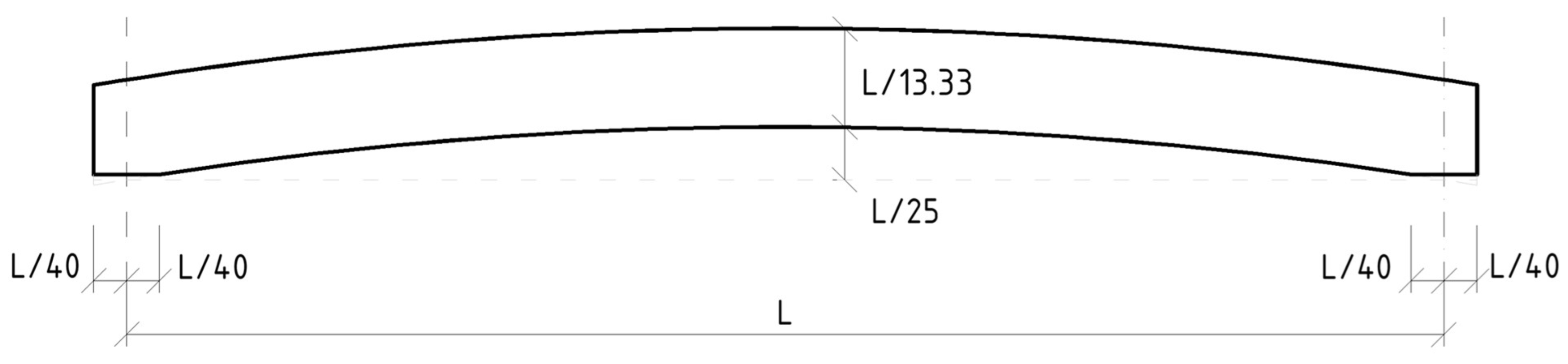
2. Parametric Study of Timber Footbridges

Optimal types of timber-based bridge systems combined with a steel member deck to be used in footbridges and small road bridges were developed in cooperation with the timber bridge execution company CB Ltd. [23], which has extensive previous experience with producing similar types of structures. The parametric numerical study was focused on timber plate-girder footbridges with bottom bridge decks consisting of appropriately combined steel and wooden members.
The main girders of the investigated footbridges consisted of two plate-girders made of glued laminated timber. They were always placed at such an axial distance as to ensure a free width of 2.8 m between them. After applying two-sided curbs with a width of 150 mm, a free width of 2.5 m of the pavement was ensured. Footbridges with spans of 12, 16, 20, and 24 m were proposed. The heights of the main girders were chosen as 1/13.33 of the respective spans and were constant along the overall lengths of the girders. The thicknesses of the girders resulted from the verification of their resistance, deformation, and dynamic response. The results were glulam girders with a cross-section of 150/900 mm for a span of 12 m, 180/1200 mm for a footbridge with a span of 16 m, 220/1500 mm for a span of 20 m, and 280/1800 mm for a footbridge with a span of 24 m. The main girders were designed with the pre-cambering of a circular arch shape; the maximum value fell in the middle of 1/25 of the span (see Figure 1).
Three types of bridge member decks were analysed. The first type was a steel member deck composed of steel cross-girders, stringers carrying the transverse wooden bridge covering and the transverse oak plank pavement, and bottom steel bracing (Figure 2). Cross-girders made of hot-rolled steel IPE 200 profiles were connected to the main girders in each span variant at axial distances of 4.0 m. The end cross-girders were made of hot-rolled profile HE200A. Two stringers made of hot-rolled steel IPE 200 profiles were connected between the cross-girders at an axial distance of 2.00 m. On the stringers’ upper flanges, a bridge covering made of oak beams with a cross-section of 200/110 mm was transversely laid. The stiffness of the bridge superstructure in the transversal horizontal direction was ensured via bottom longitudinal bracing, which was designed using hot-rolled steel angles arranged in the shape of a rhombic system under the plane of the cross-girders.
The second type of bridge deck was made up of the same structural elements as the first one. However, the stringers were designed from L 140 × 140 × 10 hot-rolled steel angles and were continuously connected with screws directly to the main girders (Figure 2). This simplified the deck, but the bridge covering, constructed using oak beams with a cross-section of 200/120 mm, contributed to the spatial effect of the overall system to a greater extent, which had to be considered in the computational model. Cross-girders and longitudinal footbridge bracings were designed with the same profiles and at the same distances as in type I.
In the third type of the proposed bridge deck, the stringers were omitted entirely. A bridge covering made of oak beams with a cross-section of 200/110 mm was placed longitudinally on the upper flanges of the cross-girders, which were, therefore, all designed with the steel wide-flange hot-rolled profile HE200A (Figure 2). The axial distance of the cross-girders was 2.0 m in each span variant. An oak pavement of 40 mm in thickness was again placed on the wooden bridge covering. In this case, the bottom longitudinal bridge bracing made of angles was arranged in the form of a K-truss system.
The parametric study was carried out using SCIA Engineer software (https://www.scia.net/en (accessed on 5 January 2023)) [24]. The main girders made of glued laminated timber were modelled using shell finite elements. All other footbridge members were considered as beam elements. Cross-girders were always modelled as hinged in the plane of the bridge deck and rigidly connected to the main beam for vertical bending. To ensure the stiffness required for main girder stability, reinforcing haunches were included at both ends of the cross-girders. Stringers in bridge deck type I were connected to the cross-girders via hinges.
Similarly, the placement of bridge coverings, if part of the individual model variant, had to allow for rotation on both main axes. All bracing joints were considered perfect hinges. For the sake of illustration, we present a geometric scheme and visualisation of computational models of footbridge superstructures with a theoretical span of 16 m, including all three types of bridge member decks considered in this study (Figure 3 and Figure 4).
Load was calculated in accordance with the applicable Eurocodes. In addition to self-weight and all permanent loads, variable traffic load was computed according to EN 1991-2 [25] in the form of a uniformly distributed load with a value of 5.0 kN∙m−2. Wind load was also considered, in accordance with EN 1991-1-4 [26].
As the first step, the stresses and deformations of individual elements were determined via static analysis. Subsequently, the resistance of the main girder against lateral–torsional buckling was verified via linear buckling analysis (LBA). The wooden members of the bridge superstructure were assessed using EN 1995-1-1 [4] or EN 1995-2 [5], whereas steel structural members were assessed in accordance with EN 1993-1-1 [27] or EN 1993-2 [28]. Finally, dynamic analysis was used to determine the natural vibration modes of the superstructures. The corresponding natural vibration frequencies were verified to ensure that they do not fall into dangerous intervals when resonance phenomena occur.
Table 1 summarises several key parameters, providing an overview of the static and dynamic behaviour of the designed footbridges. The different bridge deck types only minimally affect the stress on the main girders. The main contribution of cross-girders and bracings is to protect the main girders against lateral–torsional buckling and confer favourable dynamic properties in the horizontal direction.
In Table 1, the following designations are used:
  • σd—design value of stress caused by all relevant combinations of actions;
  • fd—design value of wood strength;
  • δk—characteristic value of the maximum deflection of main girders;
  • δlim—limit value of main girder deflection;
  • αcr—minimum force amplifier to reach elastic critical buckling;
  • fV1—value of the first natural frequency of main girder vibration in vertical direction;
  • fH1—value of the first natural frequency of main girder vibration in horizontal direction.
As we can see in Table 1, the footbridges with the larger spans already reach the interval of dangerous frequencies in the vertical direction. For spans larger than 24 m, it would probably be appropriate to increase the height of the girders to 1/12 or to 1/10 of the span. It is also obvious that the serviceability limit state, represented by the deflections of the main girders, do not play a significant role.
As for comparing between the three deck variants, bridge deck type I seems to be the least advantageous in terms of material consumption as well as production difficulty. Bridge deck type II removes some of the disadvantages of bridge deck type I. Bridge deck type III seems to be the least demanding from a structural viewpoint, and if hot-rolled IPE profiles could be used in the bridge superstructure, it would be the most advantageous in terms of steel consumption. However, due to the longitudinal placement of bridge covering on the stringers’ upper flanges, the wide-flange profiles of the HEA type must be used. Therefore, it can be concluded that all three types of bridge decks show a similar steel consumption. When deciding on a specific type of bridge deck, it is, therefore, necessary to consider the speed and simplicity of bridge assembly and the guaranteed degree of safety and durability.
Finally, it could be concluded that a rigid connection between the cross-girders and the main girders should be sufficient to protect the latter against lateral–torsional stability loss. Therefore, this connection is a very important detail which ensures the overall stiffness of the superstructure and improves its dynamic properties. The design of this connection must, therefore, minimise twist in the end node of the cross-girder. In the present study, the joint was considered fully rigid in the vertical direction. On the other hand, the connections of wooden structural members are usually considered to be nominally hinged, which is due to a slip of the joint created with dowel-type fasteners. It may be expected that the true stiffness of the joint is somewhere between these two extremes. Since this detail appeared to be essential for the design of the above-mentioned footbridge type, further attention was paid to it in our research.

3. Experimental and Numerical Analysis of the Structural Detail of Interest in a Real Footbridge

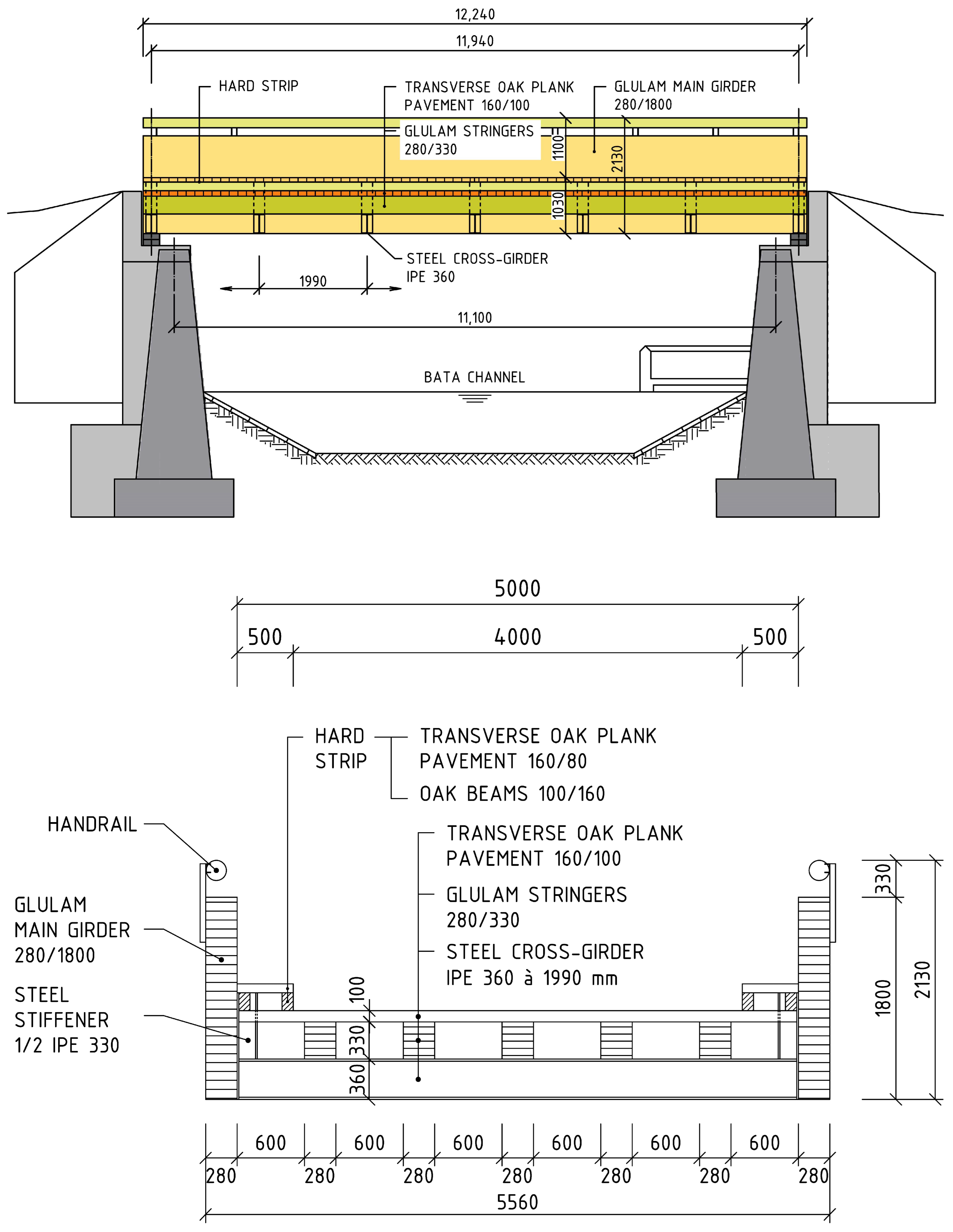
3.1. Footbridge Superstructure Description

First, we focused on the analysis of this structural detail in a real timber footbridge with possible vehicle access. This bridge is located on the Bata channel in Huštěnovice, Czech Republic. It is a simply supported plate-girder bridge with a bottom member deck. The main girders are made of glued laminated timber and have a theoretical span of 11.94 m. They are fixed at an axial distance of 5.28 m at both ends and at intervals of one-sixth of the span (i.e., at distances of 1.99 m) by steel cross-girders made of steel profiles IPE 360. On the cross-girders, continuous glulam stringers with a cross-section of 280/330 mm are placed at axial distances of 0.88 m. The stringers carry a pavement made of transverse oak planks with a cross-section of 160/100 mm. The longitudinal and cross-sectional dimensions of the tested footbridge are shown in Figure 5.
The connection of steel cross-girders to the main timber girders is achieved using 15 mm thick end plates and twelve bolts 20 mm in diameter. Together with the cross-girder, a vertical stiffener made of a “T” profile 165 mm in height (1/2 of IPE 330), welded to the overlapping end plate and the top flange of the cross-girder, forms a steel half-frame that protects the main timber girders against lateral–torsional buckling.

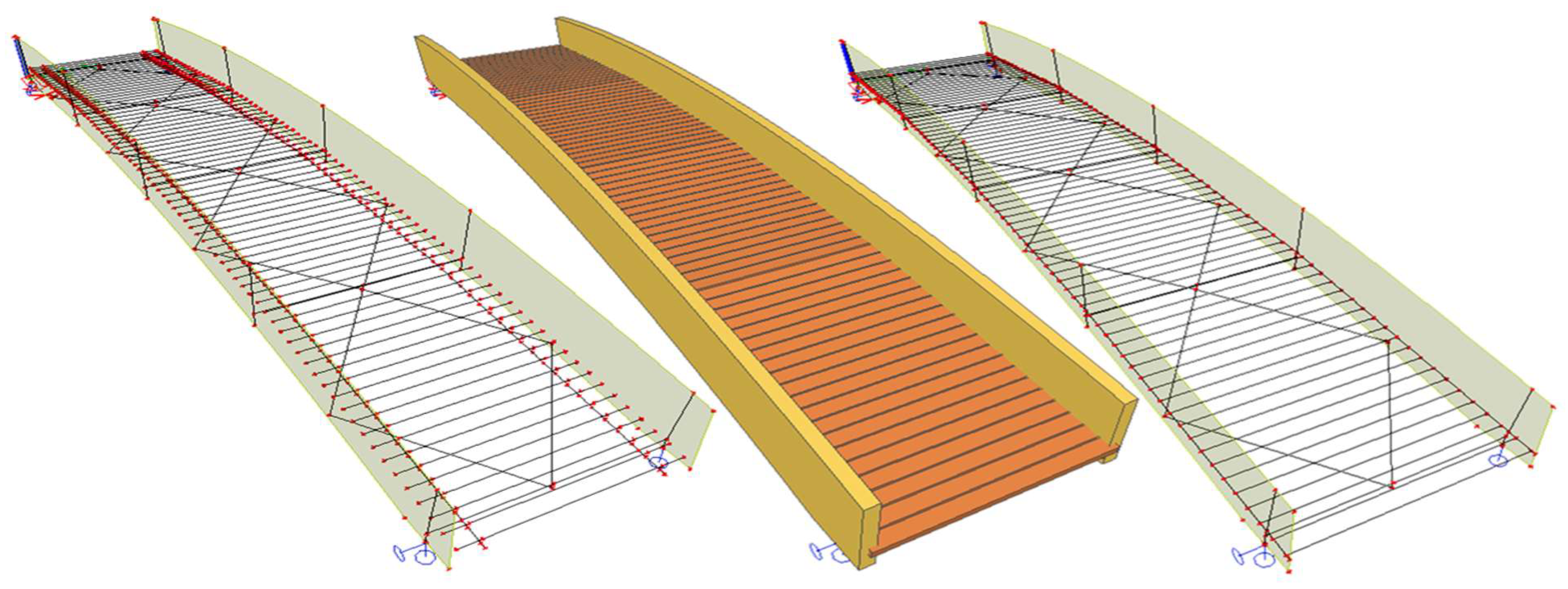
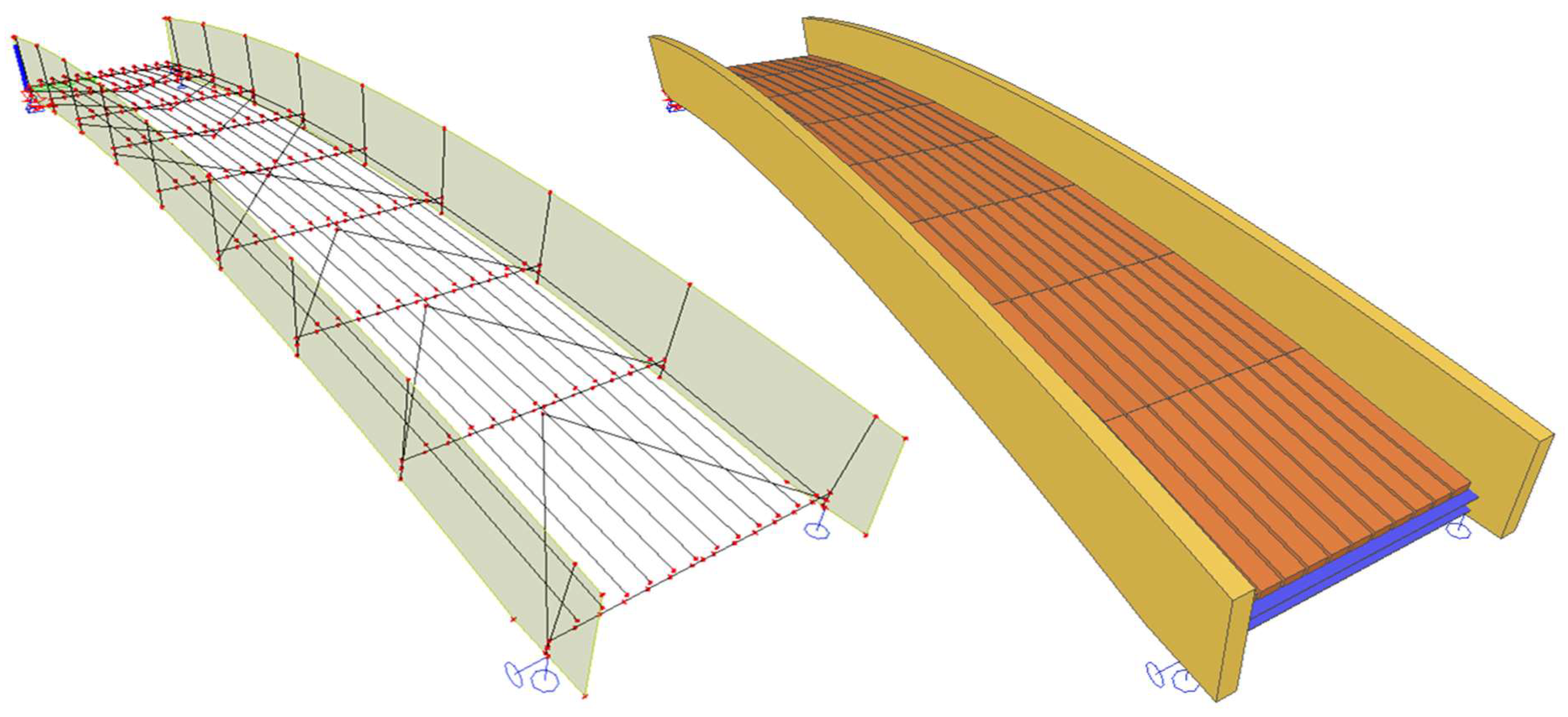
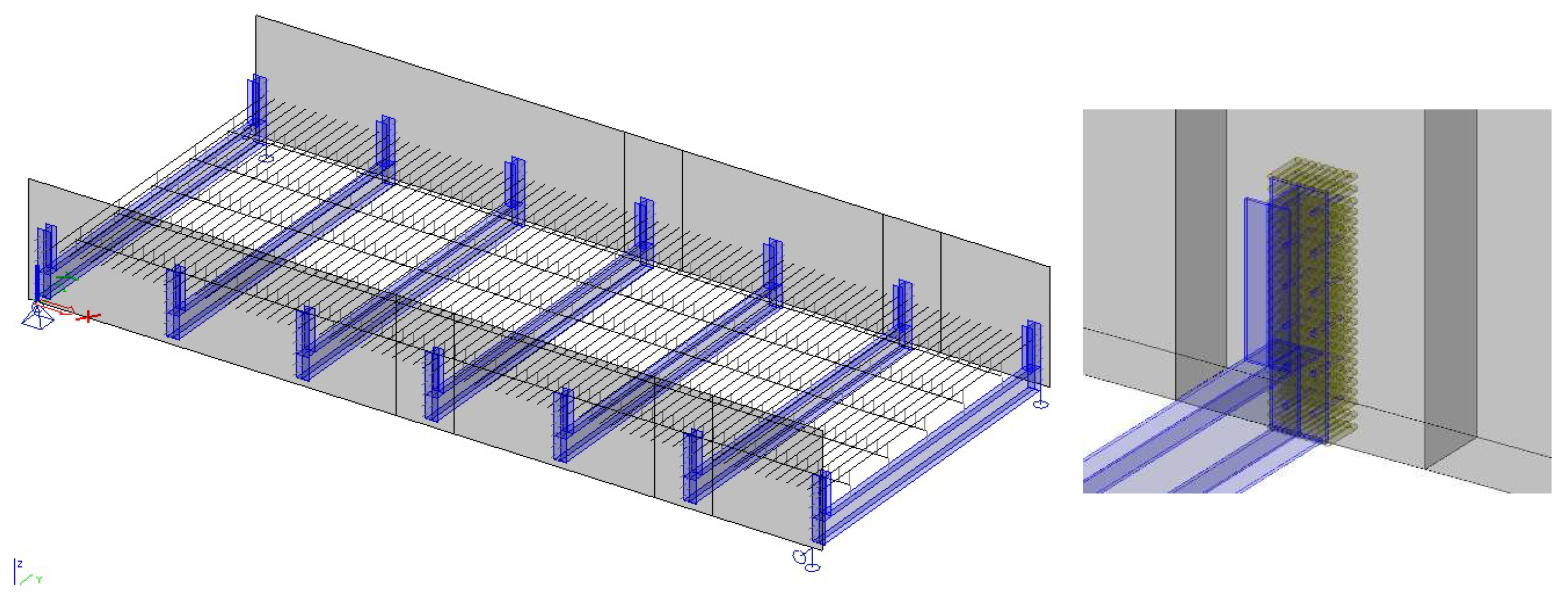
3.2. Numerical Analysis

Numerical calculations were carried out using a FEM model of the footbridge superstructure created in the SCIA Engineer software environment [24]. The processed spatial computational model (Figure 6) combines shell elements modelling main timber girders, steel cross-girders, and vertical stiffeners with beam elements modelling stringers and transversal plank pavement members. All eccentricities at the joints of members were respected in the model using fictitious perfectly rigid links—so-called rigid arms. The material parameters of the main girders and stringers were refined based on the results of non-destructive measurements conducted on the real-life bridge.
The bolts connecting the end plates to the main girders were modelled using beam elements with realistic cross-sectional and material characteristics, which were excluded from axial compressive action using local “tension-only” beam nonlinearity. Due to the software’s limitations, the contact surface between the end plate and the web of the main girder was modelled by discretely inserted beam elements made of the same material as the main girders. These contact members were placed in a suitably chosen orthogonal grid of 25/40 mm at the investigated cross-girder or 50/80 mm for other cross-girders. In contrast to the members modelling the bolts, all contact members were excluded from tension action in the model using local “compression only” beam nonlinearity.

3.3. Experimental Analysis

Based on the preliminary numerical analysis conducted using the presented model, several characteristic locations were chosen to verify the behaviour of the bridge superstructure under a testing load of a Tatra 815 truck (Tatra, Koprivnice, Czech Republic), with a total weight of 12 tons [29]. Deflections and stresses in the chosen main girder as well as those in the stringer and the cross-girder were measured during the proof-load test and were subsequently compared to the computed values.
Regarding the investigated bending stiffness of the cross-girder–main girder connection, the second steel cross-girder’s stress response from the abutment to the testing load is presented hereinafter. Normal stresses in the middle of the cross-girder and near the connection to the main girder were recorded using strain gauges, the arrangement of which is presented in Figure 7.

3.4. Comparison of Measured and Computed Results

The measured and computed results of normal stresses and deflections on the selected cross-girder are summarised in Table 1. The numerical model provides relatively good concordance in terms of stresses computed under the stringer near the main girder; however, the stresses at the connection to the main girder differ significantly from the measured values. In addition, the deflection and normal stresses computed in the middle of the cross-girder are considerably lower than the measured ones. The real-life connection seems to be less rigid than that calculated in the FEM model.
Therefore, it may be stated that the numerical model does not correspond to the real behaviour of the bridge superstructure. In the numerical model, the stress response in the upper cross-girder flange is significantly affected by local stress peaks at the discrete stringer connections. In addition, the slip in joints, which was not considered in the numerical model, is another factor that can have a considerable effect on the computed results. On the other hand, the measured values may also show some deviation, the influence of which increases with decreasing absolute values.

4. Laboratory Testing of the Structural Detail of Interest

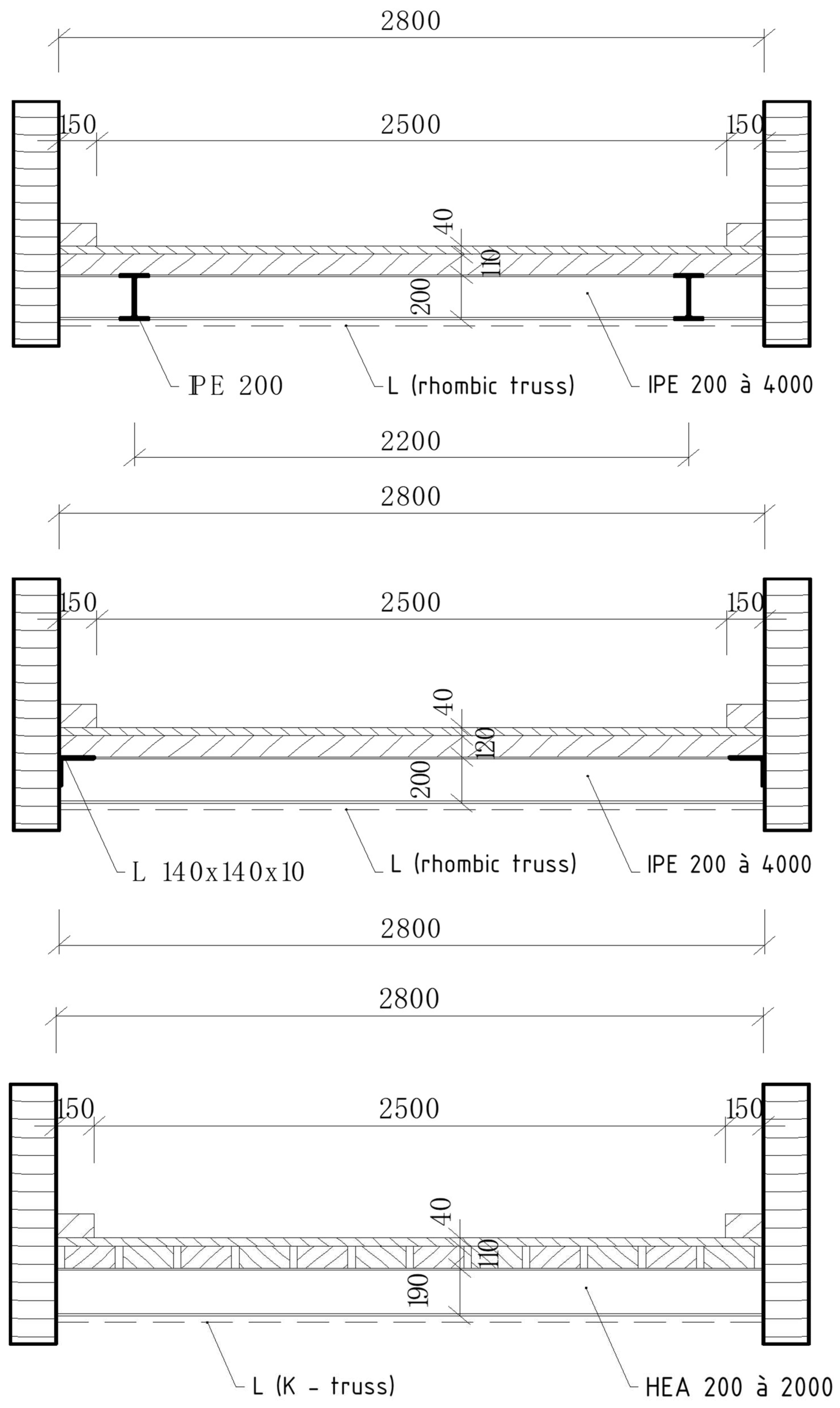
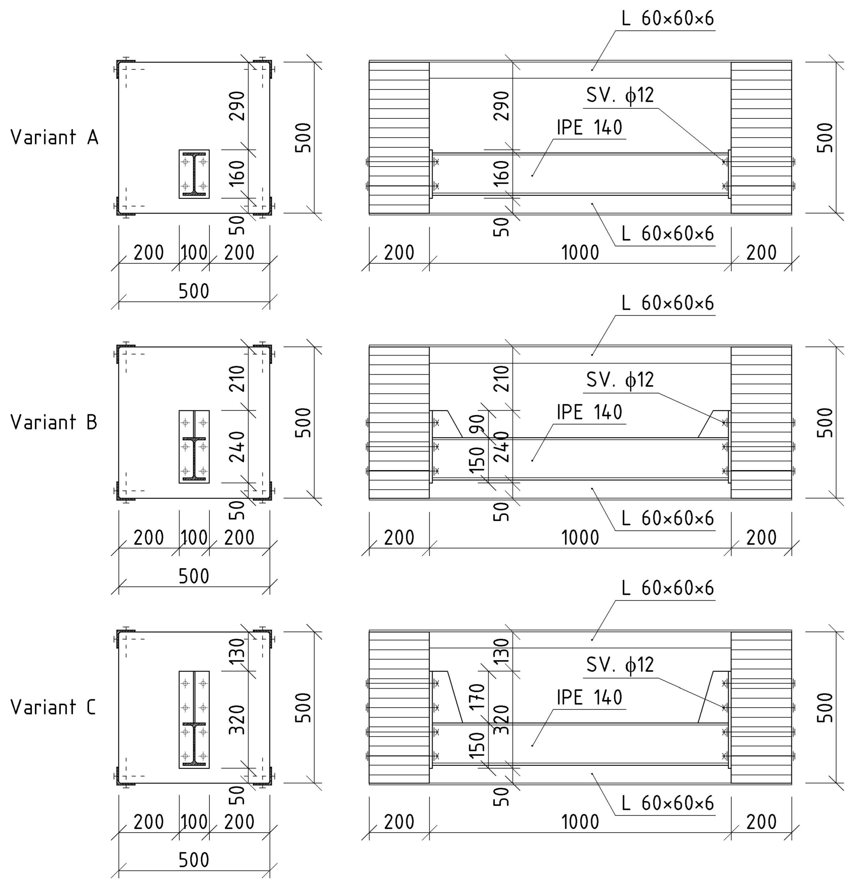
4.1. Description of Laboratory Specimens

Due to the unsatisfactory results of the experimental in situ measurements and numerical analysis of the bridge superstructure presented in Table 2, additional laboratory tests on specially designed and produced test specimens were carried out alongside more sophisticated numerical analyses. To confirm the actual behaviour of the steel-to-timber connection, nine laboratory specimens were designed and manufactured. The basic geometrical parameters of the specimens are presented in Figure 8.
Every specimen was manufactured using two 200 × 500 × 500 mm blocks made of glued laminated timber with strength class GL24h, which modelled the main timber girders. A hot-rolled steel beam made of IPE 140, steel grade S235, approximating a cross-girder, was connected to the timber blocks at their bottom edges. The timber blocks were simply supported to allow for movement in the direction of the cross-girder. In order to investigate the steel-to-timber connection only, the rotation of the timber blocks was eliminated using L60 × 60 × 6 mm hot-rolled angles fixed at all corners of the blocks. The upper angles performed the function of spacers; the angles in the lower part acted as tie rods.
The connections between the steel cross-girders and the timber blocks were constructed using 10 mm thick end plates and steel bolts of strength class 5.6 with a diameter of 12 mm.
Three variants of bolt arrangements were designed for the steel-cross-girder-to-timber-block connections; they were manufactured according to the joint stiffnesses designated for variants “A”, “B”, and “C”. Individual specimen variants differed in terms of the number of bolts situated on the cross-girder’s upper flange and the height of the end plate, depending on the height of its stiffener. Therefore, three specimens were manufactured for each of the previously mentioned variants. During laboratory tests, the cross-girder’s stress–strain response to transverse acting load was observed by means of discrete forces.

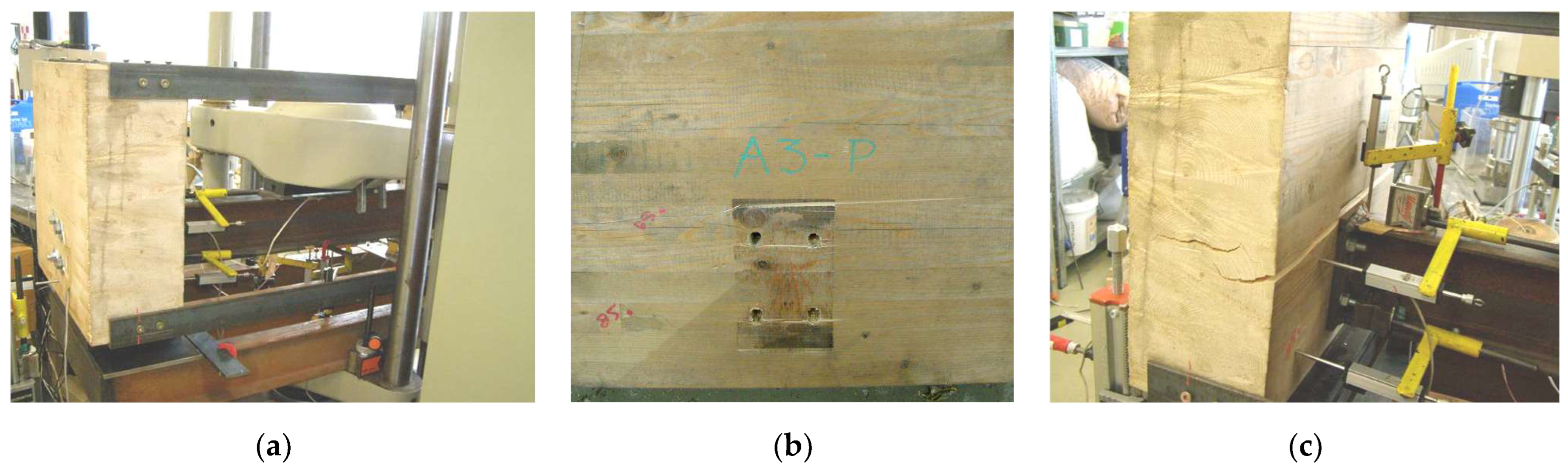
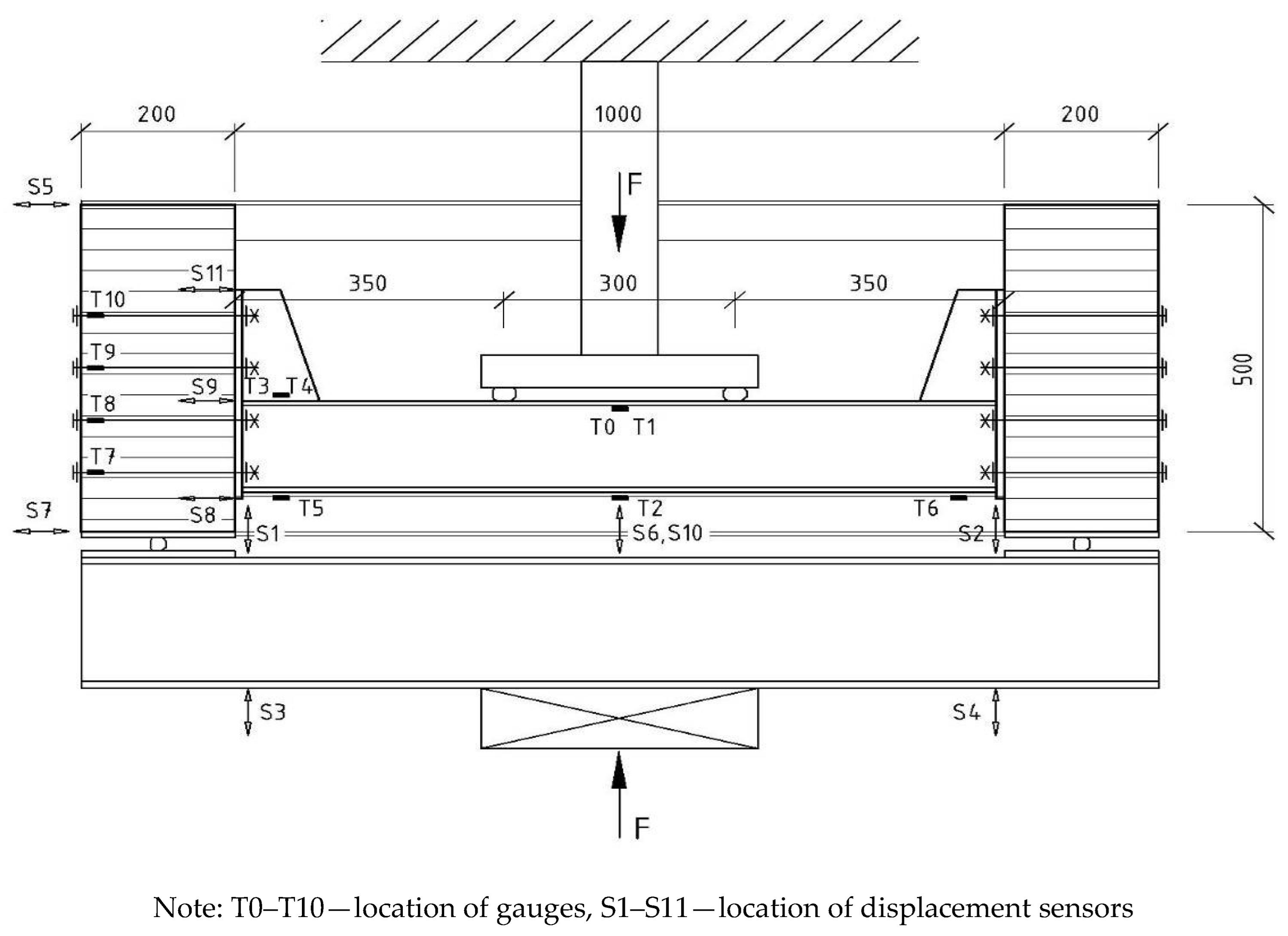
4.2. The Course of the Experiment

The stress–strain response of the steel cross-girder to the load caused by transverse acting discrete forces was observed in laboratory tests. Based on the preliminary analyses, the specimens were loaded with two forces situated symmetrically at a distance of 150 mm from the midpoint. The test arrangement of series “C” specimens subjected to the four-point bending test as well as the locations of strain gauges and displacement sensors are shown in Figure 9. The following stresses and deformations were registered during the tests:
-
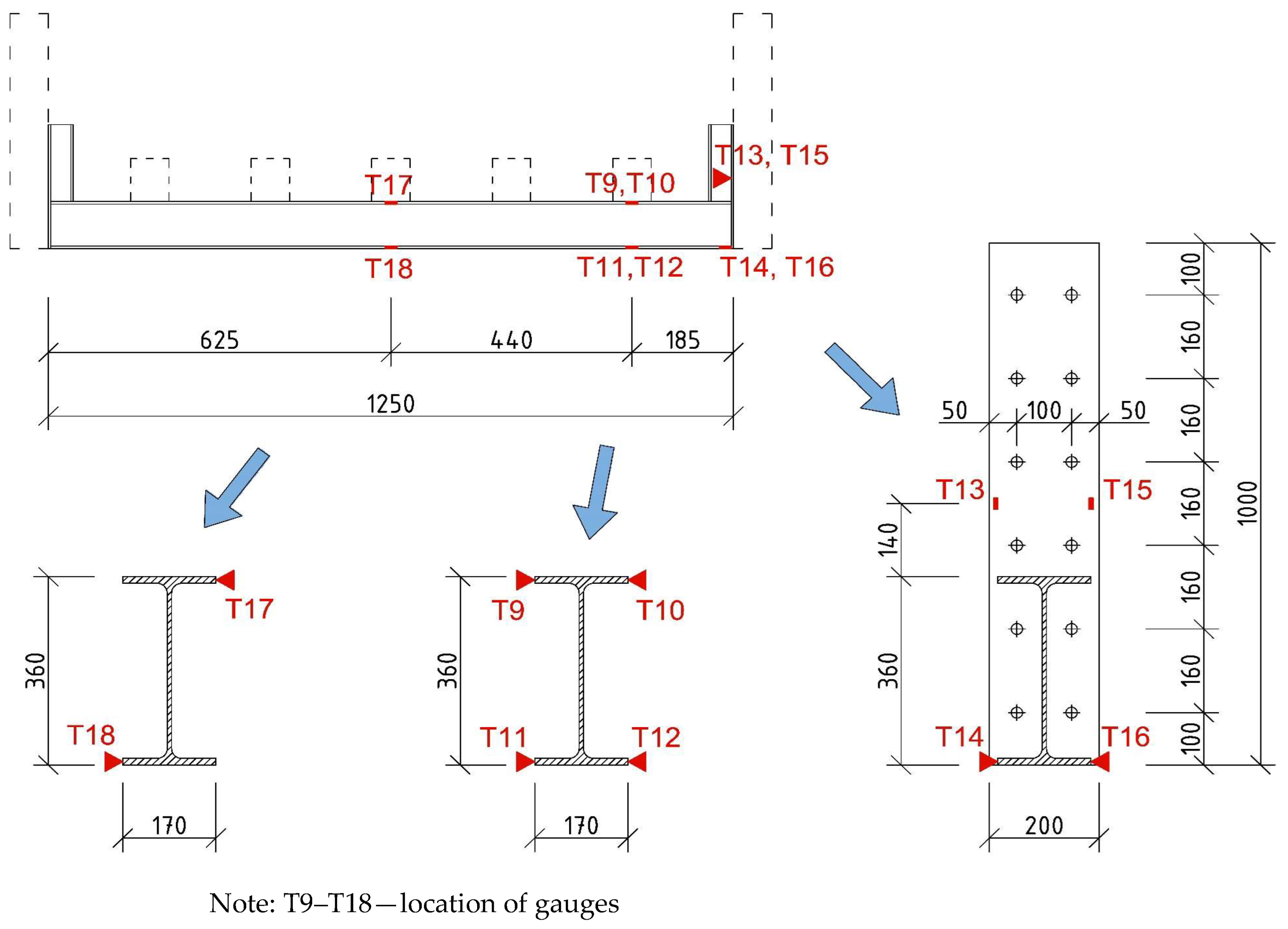
Stresses in the mid-span of the cross-girder (gauges T0, T1, and T2);
-
Stresses at the cross-girder-to-timber-block connections (gauges T3, T4, T5, and T6);
-
Stresses in the bolts (gauges T7, T8, T9, and T10);
-
Vertical deformation in the middle of the cross-girder (sensors S6 and S10);
-
Vertical deformations of the overhanging ends of the steel hydraulic press’s distribution beam (sensors S3 an S4);
-
Bolts pushing into the wooden blocks (sensors S1 and S2);
-
Absolute rotations of the wooden blocks (based on the horizontal deformations of the top and bottom edges of the wooden blocks measured by sensors S5 and S7);
-
Relative rotations of the end plate against the wooden blocks (sensors S8, S9, and S11).
A hydraulic press was used to produce the pressure needed for specimen testing. At the beginning, every sample was loaded with a force of 5.0 kN divided into two half forces. This force introduced the basic load level of all tested specimens. Consequently, the samples were tested by gradually increasing the force by a step of 5.0 kN in the case of specimens in series “A” and 10.0 kN in the case of specimens in series “B” and “C”. After each loading step, the specimens were unloaded to the basic loading level. The test continued until the samples collapsed, which was due to either a bearing failure of the wood or the wood splitting in the direction perpendicular to the grain because of transverse bending of the timber blocks (Figure 10).

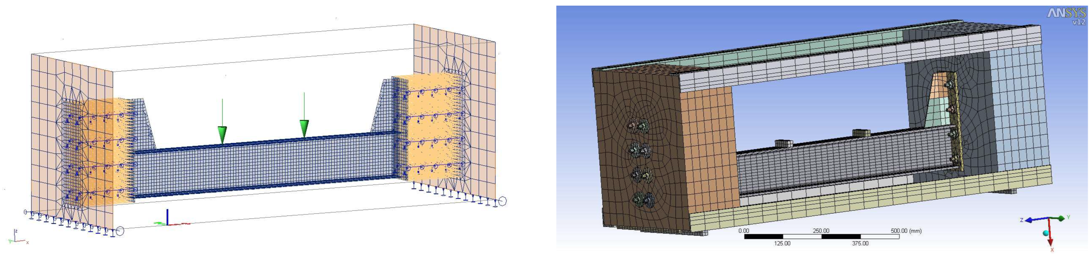
5. Numerical Analysis of the Tested Specimens

Two computational models were used to numerically analyse each of the three tested sample variants. The first model was created using the software SCIA Engineer [24] by combining shell and beam finite elements. Shell elements with the corresponding thicknesses were used to approximate the timber blocks and cross-girders, including all parts of their connections to the timber blocks, i.e., end plates and stiffeners. Beam elements modelled the stiffening angles and bolts connecting the end plates to the timber blocks. To model the joint itself, the approach used during the creation of the superstructure model was utilised (see Section 3.2). Slips between steel end plates and timber blocks due to the bolt shafts being pushed into wood were accounted for by means of linear elastic supports of the beam elements simulating the bolts. The stiffness of the support was derived from the modulus of elasticity perpendicular to the grains.
Since the model described above was not able to adequately consider the behaviour of the connection between the cross-girder and the wooden blocks, a more sophisticated model was created in the ANSYS software environment (http://www.ansys.com/Industries/Academic (accessed on 28 March 2024)) [30] using 3D finite elements SOLID186 and SOLID187. This software allows for an optimised consideration of the plasticity and orthotropic properties of wood and the contact points between connected members. Using special contact finite elements, CONTA174, combined with elements TARGE170, bolt deformations and stresses at the contact points between the end plates and the timber blocks were calculated to more precisely reflect actual joint behaviour. Both numerical models of specimen variant “C” are shown in Figure 11. Firstly, the previously mentioned models were used for preliminary calculations to optimise the course of the laboratory tests. After experimental analyses, both models were modified implementing the actual material characteristics; they were then used for detailed numerical analyses of the tested samples. The following physical and mechanical properties of the timber blocks were obtained by means of tests performed in accordance with EN 384 [31] and used in numerical calculations:
-
Mean value of wood density, ρm = 433.1 kg∙m−3;
-
Characteristic value of wood density, ρk = 416.0 kg∙m−3;
-
Characteristic elasticity modulus of timber blocks in tension and compression, E0,05 = 8764.4 MPa;
-
Mean value of elasticity modulus in tension and compression parallel to wood grains, E0,mean = 13,081.2 MPa;
-
Mean value of elasticity modulus in tension and compression perpendicular to the wood grain, E90,mean = 436.0 MPa and
-
Mean value of shear elasticity modulus, Gmean = 817.6 MPa.

6. Comparison of Measured and Computed Results

Figure 12 and Figure 13 show a comparison of selected experimental results with the corresponding theoretical outputs obtained from both numerical models described in Section 5 (excluding specimen A1, of which its measurement failed during testing). Vertical deformations of the cross-girder in the middle of its span were purged from pushing bolts into the wooden blocks. The rotations of the end plates were specified using the measured and computed values of horizontal deformations.

7. Conclusions

The results of the experimental and numerical analyses confirmed that the cross-girder stress–strain response is heavily dependent on joint arrangement and stiffness.
-
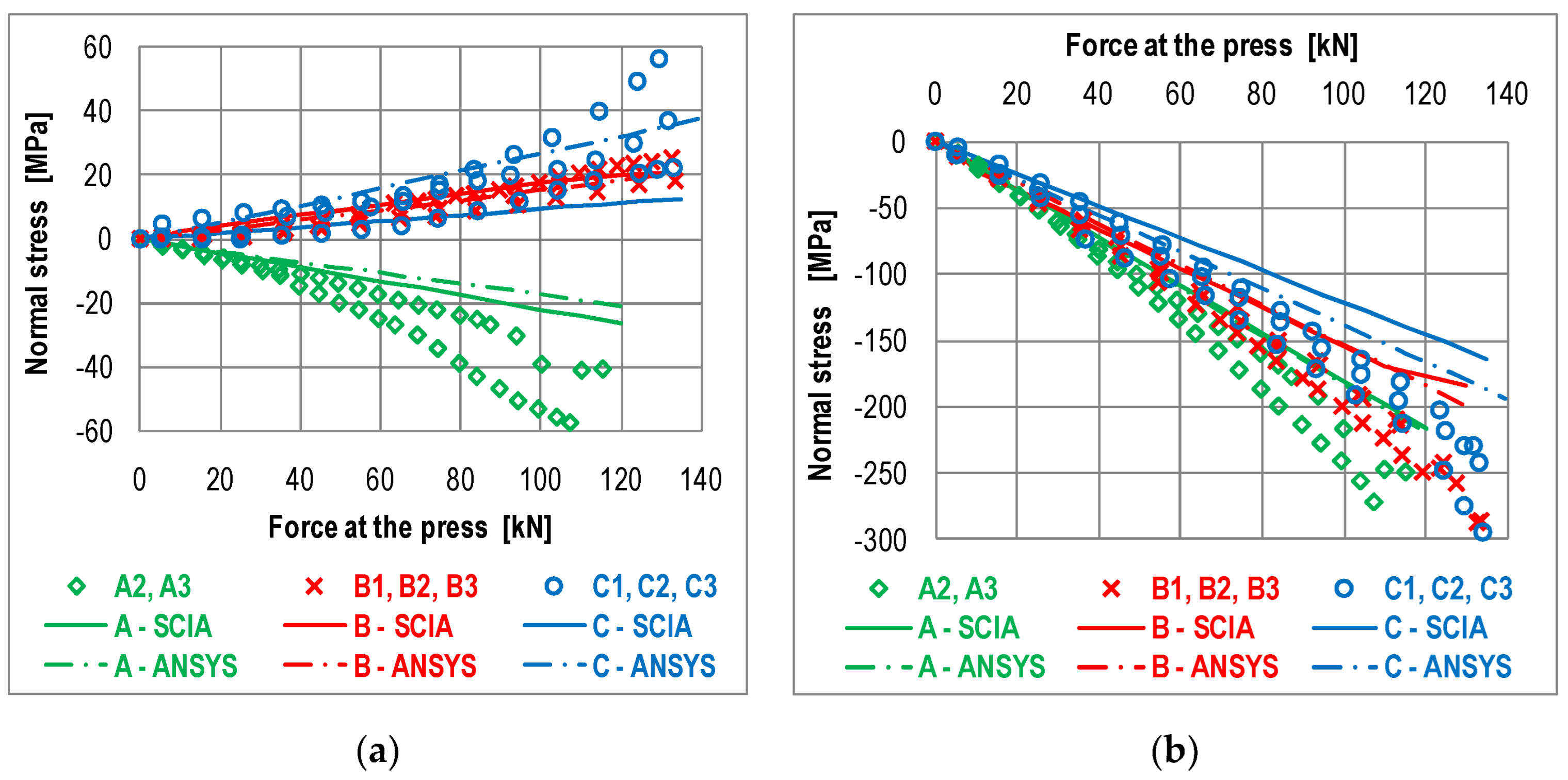
The behaviour of a steel-cross-girder-to-timber-block connection manufactured without a corner stiffener seems to be very close to that of a nominally hinged joint. This is confirmed by the compression stresses in the upper flange of the cross-girder (Figure 12a), which were present even at a distance of 50 mm from the wooden block. The compression stresses were caused due to a small positive bending moment;
-
Joint stiffness was increased due to the addition of a stiffener with one or two rows of bolts above the upper cross-girder flange, which caused tensile stresses in the upper cross-girder flange (Figure 12a);
-
Because of increasing joint stiffness, a decreasing absolute value of stresses in the cross-girder midpoint was observed (Figure 12b), corresponding to the redistribution of the bending moment from the mid-span to the connection with the timber blocks;
-
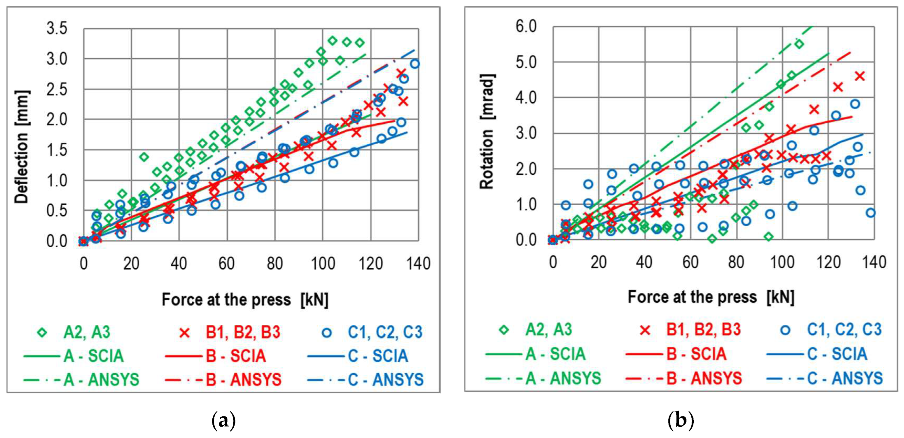
The higher joint stiffness in samples “B” and “C” was also proved by the lower values of cross-girder deflection in its mid-span (Figure 13a) and by rotations of the end plate towards the wooden blocks;
-
The most rigid connection with joint arrangement was observed in the specimens in series “C”. Normal stresses in the cross-girder mid-span decreased by about 33% in comparison to stresses arising in the same place in specimens of series “A”;
-
In a fully rigid joint, there should be a 65% decrease in stress. This corresponds to the reduction in the bending moment in the mid-span of the cross-girder from M = 0.35·F/2, valid for a double-hinged girder, to M = 0.1225·F/2 in the case of a double-fixed girder, where “F” is the value of the acting force, according to Figure 9;
-
The deflection of the cross-girder mid-point decreased by about 55% in specimens in series “C” compared to series “A”, while it should decrease by 79% in the case of full fixation;
-
Values obtained through experimental analyses naturally show some dispersion due to the large variance in physical and mechanical properties in wood. The end plate rotations calculated from the measured horizontal deformations in particular vary significantly. This can be explained by the significant sensitivity of the calculated rotation value to the accuracy of measurement of horizontal displacements of the end plate against the timber block;
-
A very important factor influencing joint behaviour is also the way in which they are assembled, especially the level of the prestress in bolts. Bolt prestress increases the friction on the surface between the steel end plate and the timber block, and so the shear resistance of the connection is also enhanced. Naturally, prestress in bolts also increases initial joint rotation stiffness. However, since the level of prestress in bolts was not controlled during the construction of the footbridge analysed in this study, it was not taken into account during numerical analyses.
The results of the presented numerical and experimental analyses confirm that the behaviour of the investigated structural detail is semi-rigid. Its bending stiffness especially depends on joint arrangement and on its manner of assembly.
An approximation of the structural joint as a perfect hinge may be accepted for preliminary global analysis or in the case of local cross-girder analysis to determine the maximum traffic action effect in the cross-girder mid-point. However, in the case of detailed structural analyses, such as main girder stability verification or dynamic behaviour investigation of a footbridge superstructure, the actual joint stiffness should be considered, for instance, by means of elastic fixation. How to determine the joint stiffness parameters of the aforesaid structural detail is discussed, for example, in [32], where the component method, usually used for steel joints, is applied.

Author Contributions

Numerical analyses in the parametric study on timber plate-girder footbridges—J.G., J.O. and A.W.-P.; numerical analysis of the real footbridge—J.G.; preparation, execution, and processing of the results of experimental measurements of the real footbridge—F.B., J.G., R.H. and J.V.; preparation, execution, and processing of the results of laboratory measurements—F.B., J.G., J.O., R.H. and J.V.; numerical analyses of the tested steel-to-timber connection—R.H. and J.G.; supervision and coordination of individual works—J.V. and J.O.; project administration—J.V. and J.O.; writing: preparation of the original draft—J.G. and J.O.; writing: review and editing—A.W.-P. and J.V. All authors have read and agreed to the published version of the manuscript.

Funding

This research was supported by the Scientific Grant Agency of the Slovak Republic under the project 1/0472/24.

Institutional Review Board Statement

Not applicable.

Informed Consent Statement

Not applicable.

Data Availability Statement

The raw data supporting the conclusions of this article will be made available by the authors upon request.

Conflicts of Interest

The authors declare no conflicts of interest.

References

  1. Structural Timber Association, Technical Bulletin 01—Timber as a Structural Material—An Introduction. Available online: https://www.structuraltimber.co.uk/ (accessed on 28 March 2024).
  2. Crocetti, R. Timber Bridges: General Issues, with Particular Emphasis on Swedish Typologies. In Proceedings of the 20th Internationales Holzbau-Forum (IHF 2014), Garmisch-Partenkirchen, Germany, 3–5 December 2014. [Google Scholar]
  3. EN 1990; Eurocode. Basis of Structural Design. CEN: Brussels, Belgium, 2002.
  4. EN 1995-1-1; Eurocode 5: Design of Timber Structures—Part 1-1: General Common Rules and Rules for Buildings. CEN: Brussels, Belgium, 2006.
  5. EN 1995-2; Eurocode 5: Design of Timber Structures—Part 2: Bridges. CEN: Brussels, Belgium, 2004.
  6. Juttila, A.; Mäkipuro, R.; Salokangas, L. Testing a Wood-Concrete Composite Bridge. Struct. Eng. Int. 1997, 7, 275–277. [Google Scholar] [CrossRef]
  7. Gustafsson, M. Two Timber Footbridges, Sweden. Struct. Eng. Int. 1993, 3, 75–76. [Google Scholar] [CrossRef]
  8. Svensson, H.S.; Maier, M. Long-Span Pedestrian Timber Truss Bridge Across the Dahme River at Berlin. Innov. Wooden Struct. Bridges 2001, 85, 239–244. [Google Scholar]
  9. Gerold, M. Pedestrian and Cyclic Bridge near Rheinfeld, Germany. Struct. Eng. Int. 2000, 10, 155–157. [Google Scholar] [CrossRef]
  10. Liuzzi, M.A.; Fiore, A.; Greco, R. Some Structural Design Issues on a Timber Bridge for Pedestrians. OPTARCH 2019, 44, 583–590. [Google Scholar] [CrossRef]
  11. Pedrazzi, G.; Beltrami, C. Design of long span timber footbridge. In Proceedings of the International Conference on the Design and Dynamic Behaviour of Footbridges, Paris, France, 20–22 November 2002; pp. 1–11. [Google Scholar]
  12. Conzett, J. The Traversina footbridge, Switzerland. Struct. Eng. Int. 1997, 7, 92–94. [Google Scholar] [CrossRef]
  13. USFS. Timber Bridge Manual; Minnesota Department of Transportation: St. Paul, MN, USA, 1992. Available online: https://www.dot.state.mn.us/bridge/pdf/insp/USFS-TimberBridgeManual/index.html (accessed on 28 March 2024).
  14. Available online: https://puuinfo.fi/puutieto/wooden-bridges/?lang=en (accessed on 28 March 2024).
  15. Seppälä, M.; Ilgın, H.E.; Karjalainen, M.; Pajunen, S. An Analysis on Finnish Wooden Bridge Practices. Appl. Sci. 2023, 13, 4325. [Google Scholar] [CrossRef]
  16. Fojtík, R.; Lokaj, A.; Gabriel, J. Timber Bridges and Footbridges; Monograph (in Czech). Information Centre of Czech Chamber of Authorized Engineers and Technicians Active in Construction: Prague, Czech Republic, 2017. [Google Scholar]
  17. Zobel, H.; Al-Khafaji, T. Contemporary structural solutions of timber pedestrian bridges. In Proceedings of the 4th International Conference Footbridge 2011, Wroclaw, Poland, 6–8 July 2011; pp. 56–73. [Google Scholar]
  18. Billiszczuk, J.; Hawryszków, P.; Sułkowski, M.; Maury, A.; Węgrzyniak, M. A Cable-Stayed Footbridge Made of Glued-Laminated Wood—Design, Election and Experimental Investigations. In Dorogi i Mosti [Roads and Bridges]; NIDI: Kyiv, Ukraine, 2008; Volume 10, pp. 20–28. Available online: http://dorogimosti.org.ua/en (accessed on 28 March 2024). (In English)
  19. Luggin, W.F.; Luggin-Erol, K. Historic Timber Bridge System, Böheimkirchen, Austria. Struct. Eng. Int. 2002, 12, 182–184. [Google Scholar] [CrossRef]
  20. Halaczek, B.; Knight, M. A New, Sustainable Bridge Form, The Margaretengurtel Bridge, Vienna. In Proceedings of the 4th International Conference Footbridge 2011, Wroclaw, Poland, 6–8 July 2011; pp. 250–251. [Google Scholar]
  21. Bajzecerová, V.; Kánocz, J.; Rovňák, M.; Kováč, M. Prestressed CLT-concrete composite panels with adhesive shear connection. J. Build. Eng. 2022, 56, 104785. [Google Scholar] [CrossRef]
  22. Concrete and Timber Services, Ltd. Available online: https://www.ctsbridges.co.uk/bridges/steel-and-timber/ (accessed on 28 March 2024).
  23. CB, Ltd., Kunovice, Czech Republic. Available online: https://www.ekatalog.cz/firma/270267-cb-sro/ (accessed on 28 March 2024).
  24. SCIA Engineer. Structural Analysis Software. Available online: https://www.scia.net/en (accessed on 5 January 2023).
  25. EN 1991-2; Eurocode 1. Actions on Structures—Part 2: Traffic Loads on Bridges. CEN: Brussels, Belgium, 2003.
  26. EN 1991-1-4; Eurocode 1: Actions on Structures—Part 1-4: General Actions—Wind Actions. CEN: Brussels, Belgium, 2010.
  27. EN 1993-1-1; Eurocode 3: Design of Steel Structures—Part 1-1: General Rules and Rules for Buildings. CEN: Brussels, Belgium, 2005.
  28. EN 1993-2; Eurocode 3: Design of Steel Structures—Part 2: Steel bridges. CEN: Brussels, Belgium, 2006.
  29. Vičan, J.; Hlinka, R.; Bahleda, F.; Lokaj, A. Experimental Verifying of the Timber Bridge Superstructure Behaviour. In Proceedings of the Conference: Wooden Constructions and Structures Based on Wood, Štramberk, Czech Republic, 11–12 November 2009; pp. 114–119. (In Slovak). [Google Scholar]
  30. ANSYS, Inc. ANSYS Academic Research. Available online: http://www.ansys.com/Industries/Academic (accessed on 28 March 2024).
  31. EN 384; Structural Timber. Determination of Characteristic Values of Mechanical Properties and Density. CEN: Brussels, Belgium, 2016.
  32. Odrobiňák, J.; Vičan, J. Establishment of the Component Method for a Semi-rigid Steel-Timber Joint. In Proceedings of the Conference: Timber Structures, Habovka, Slovakia, 3–4 June 2010; pp. 87–92. (In Slovak). [Google Scholar]
Figure 1. Shape of the main girder of the investigated footbridges.
Applsci 14 03070 g001
Figure 2. Cross-sections of the investigated timber footbridges (dimensions are given in mm).
Applsci 14 03070 g002
Figure 3. Geometric scheme and visualisation of 16 m span footbridge model, bridge deck types I and II.
Applsci 14 03070 g003
Figure 4. Geometric scheme and visualisation of 16 m span footbridge model, bridge deck type III.
Applsci 14 03070 g004
Figure 5. Longitudinal section and cross-section of the tested footbridge (dimensions are given in mm).
Applsci 14 03070 g005
Figure 6. Numerical model of the tested footbridge and detail of the modelled cross-girder connection.
Applsci 14 03070 g006
Figure 7. Arrangement of installed gauges on the chosen cross-girder.
Applsci 14 03070 g007
Figure 8. Geometrical parameters of laboratory specimens (dimensions are given in mm).
Applsci 14 03070 g008
Figure 9. Arrangement of specimen “C” during the test (dimensions are given in mm).
Applsci 14 03070 g009
Figure 10. Photos from the experimental measurements: (a) view of specimen A3 during the test, (b) bearing failure of the bolted connection, (c) splitting of wood due to transverse bending of the timber blocks.
Applsci 14 03070 g010
Figure 11. Numerical FEM models of specimen variant “C” in SCIA Engineer and in ANSYS.
Applsci 14 03070 g011
Figure 12. Comparison of measured and computed normal stresses in the upper flange of the cross-girder: (a) at the connection and (b) in the middle of the span.
Applsci 14 03070 g012
Figure 13. Comparison of measured and computed deformations of the cross-girder: (a) deflection in the middle and (b) rotation of the end plate towards the timber block.
Applsci 14 03070 g013
Table 1. Summary of results of the parametric study.
SpanMain Girder Cross-Section
[mm]
Compared ValuesFootbridge Deck Type
Type IType IIType III
12150/900Resistanceσd/fd[-]0.880.830.81
Deflectionδklim[-]0.470.550.50
Stabilityαcr[-]16.0522.8424.70
DynamicfV1[Hz]6.326.486.21
fH1[Hz]8.897.388.03
16180/1200Resistanceσd/fd[-]0.840.710.76
Deflectionδklim[-]0.570.530.64
Stabilityαcr[-]17.7526.7517.36
DynamicfV1[Hz]5.515.955.98
fH1[Hz]4.966.826.45
20220/1500Resistanceσd/fd[-]0.730.600.66
Deflectionδklim[-]0.640.590.71
Stabilityαcr[-]22.7529.2317.00
DynamicfV1[Hz]5.005.395.22
fH1[Hz]3.685.395.22
24260/1800Resistanceσd/fd[-]0.680.580.62
Deflectionδklim[-]0.690.600.75
Stabilityαcr[-]29.4231.2816.87
DynamicfV1[Hz]5.015.215.13
fH1[Hz]3.555.204.75
Table 2. Measured and computed values of stresses [MPa] and deflections [mm] of the observed steel cross-girder.
Value SourceUnder the Outer StringerAt Joint to Main GirderIn the Middle
T9T10T11T12T13T14T15T16T17T18Deflection
Measurement−11.0−17.518.514.46.9−0.4−1.0−0.4−42.142.32.8
Numerical calculation−14.8−13.518.219.15.1−8.75.5−5.7−27.132.11.9
Disclaimer/Publisher’s Note: The statements, opinions and data contained in all publications are solely those of the individual author(s) and contributor(s) and not of MDPI and/or the editor(s). MDPI and/or the editor(s) disclaim responsibility for any injury to people or property resulting from any ideas, methods, instructions or products referred to in the content.

