Abstract
Electric vehicles (EVs), which are environmentally friendly, have been used to minimize the global warming caused by fossil fuels used in vehicles and increasing fuel prices due to the decrease in fossil resources. Considering that the energy used in EVs is obtained from fossil resources, it is also important to store and use energy efficiently in EVs. In this context, recovery from a regenerative braking system plays an important role in EV energy efficiency. This paper presents a fuzzy logic-based hybrid storage technique consisting of a supercapacitor (SC) and battery for efficient and safe storage of a regenerative braking system. First, the constraints of the battery to be used in the EV for fuzzy logic control are identified. Then, the fuzzy logic system is created and tested in the ADVISOR and Siemens Simcenter Flomaster programs in the New European Driving Cycle (NEDC) driving cycle. A SC was selected for primary storage to prevent the battery from being continuously charged from regenerative braking, thus reducing its lifetime. In cases where the vehicle consumes more energy than the average energy consumption, energy consumption from the battery is reduced by using the energy stored in the SC, and the SC energy is discharged, making preparations for the energy that will come from the next regenerative braking. Thus, the high current values transferred to the battery during regenerative braking are effectively limited by the SC. In this study, the current values on the battery in the EV with a hybrid storage system decreased by 29.1% in the ADVISOR program and 28.7% in the Simcenter Flomaster program. In addition, the battery generated 46.84% less heat in the hybrid storage system. Thus, the heating and capacity losses caused by this current on the battery were minimized. The presented method provides more efficient energy management for EVs and plays an important role in maintaining battery health.
1. Introduction
Nowadays, the production of EVs is rapidly increasing. While the total number of EVs worldwide was less than 200,000 in 2010, this value has increased approximately 55 times in the last 10 years with the increase in mass production and reached 11 million [1,2]. Carbon emissions are one of the main causes of global warming and air pollution. The use of fossil fuels is one of the most important sources of CO2 emissions into the atmosphere. In 2020, it was stated that 25% of CO2 emissions in air pollution originate from the transportation sector [3]. Moreover, road transport accounts for 53% of carbon emissions in global trade-related transport, and this share is expected to increase to 56% by 2050 if the current trends continue [4]. By 2050, the number of light commercial vehicles is expected to increase by more than 100% of the current level, on average over 2 billion. [5]. Therefore, if there are no changes in vehicle production and vehicle fuel consumption, no reduction in GHG emissions from environmental and air pollution is expected in the coming decades. In this context, in order for countries to achieve net-zero emissions as required by the Paris Agreement, all road transportation should be provided by EVs. [6]. In this rapid transformation, users’ demands for longer-range, safer, and long-lasting batteries must be met.
The biggest challenge in the deployment of EVs lies in the development of low-cost and high-range battery systems [7]. Because the production of low-cost batteries will enable us to see more EVs on the roads, battery manufacturers are investing heavily in their facilities [8,9]. It is desirable that the batteries used in EVs have high power and energy densities. However, EVs have not yet reached the targeted energy density [10]. To overcome this problem arising from batteries, the first work to be done brings with it the necessity of using energy in the most efficient way in EVs. Scientific studies conducted for this purpose have shown that regenerative braking can increase the range of EVs by 20–30% [11,12,13]. However, electrical conditions such as fast charging and frequent charging, which we can see as the reason for this situation, cause negative effects on the vehicle battery and cause the battery pack or battery cells to deteriorate [14,15,16,17]. In addition to increasing the range of EVs, preventing battery aging is critical for ensuring economic and environmental sustainability.
Although significant advances in battery performance have been made recently [18,19], damage to batteries due to sudden energy demands is a common problem, especially in intensive use. This is due to the rapid charging/discharging of batteries during the acceleration and braking of EVs [20]. Batteries perform better when charged/discharged with a low current because the chemical reactions occur continuously and regularly [21]. However, when EVs require instantaneous power consumption during acceleration, batteries meet this demand with high current values [21,22]. Likewise, when a high current is stored in the batteries during regenerative braking, this variable current can shorten the life of the battery. When such acceleration and regenerative braking situations are repeated frequently, especially in urban driving, the battery’s life can be negatively affected [23].
Various battery types are used in EVs, but the most promising, and currently the most common type of energy storage, is the lithium-ion (Li-ion) battery [24,25]. While Li-ion batteries have a high energy density, their power density is not high enough [26]. Supercapacitors (SCs) have similar electrochemical systems for energy storage and allow fast charge/discharge processes [27]. Due to their low energy density compared with batteries, they cannot be directly used as a power source for EVs [27,28,29]. However, they are a good option for compensating for high use intensity in short time periods when the battery power is insufficient. Thus, in hybrid storage EVs with SC, the battery is protected from high currents and overheating.
In the late 1990s, SCs were introduced by investigating their performance for fast energy harvesting and sudden acceleration during braking and downhill descent via a SC unit consisting of 40 × 2 SCs (Panasonic, 2.3 V, 1800 F) installed in a Mazda Bongo Friendee [30]. At the same time, hybridization of SCs with EV batteries, such as valve-regulated lead-acid (VRLA), nickel-metal hydride (Ni-MH), lithium-ion (Li-ion), and PbA batteries, has been proposed [31,32,33,34]. Researchers have stated that SCs may appear as an alternative to replace existing storage batteries, as energy density is less important than power density for vehicle acceleration [34,35,36,37]. It has also been stated that a successful energy storage system should provide more power by improving the vehicle’s performance; the storage system should have a longer operating life, stable performance at low temperatures, and be lighter and smaller in size [37]. However, the ultimate use of this application will depend on the development of this system and consumer demand. Recent studies have shown that consumers are reluctant to choose EVs unless they can be used for transportation over longer distances without range anxiety [38]. Although SCs are not suitable for use as a stand-alone storage source in EVs, they are a very suitable storage source for the hybrid storage option.
Due to the high cost of SCs, battery–SC hybrid systems have not been widely adopted or used compared with Li-ion batteries [39]. The most important reason for this is that the price of a SC with the same energy capacity as a Li-ion battery is 275% higher [40]. However, studies have shown that the price difference between the lifecycle of SCs and Li-ion batteries is a false issue when the entire lifetime of the EV is considered [41,42,43]. Studies have shown that hybrid energy storage systems (HESS) with SCs increase the cost by about 25% but reduce the operating costs by 10% to 27% by extending the battery life [42].
In addition to all these advantages, an important advantage of SCs compared to Li-ion batteries is that they have a wide operating temperature range (−20 °C to +80 °C) [44,45]. This provides an advantage in the use of battery–SC hybrid storage systems in EVs. Thus, using SCs outside the temperature limits of Li-ion batteries can help extend the lifetime of energy sources. A wider temperature range can facilitate fast charging. The management of HESS is important and needs to be compatible with the air and liquid thermal management systems. Another advantage of battery–SC HESSs for EVs is that they do not pose a risk of ignition and combustion in the event of a traffic accident [46].
The main objective of this study is to increase the battery life by reducing the negative effects of regenerative braking on the battery in EVs. Since the battery is one of the most costly components of EVs, a SC was first used to reduce the charge/discharge cycles. The limitations between these storage components were determined by a fuzzy logic controller. In the study, battery tests were performed using two different simulation programs to demonstrate the effect of this method on the battery. The ADVISOR and Siemens Simcenter Flomaster programs were used to perform the tests in the NEDC cycle. In this way, the effect of the HESS with a SC on battery aging was determined. A review of the existing literature shows that while the studies generally focus on how the regenerative braking system works and how the energy is collected, there are limited studies on how to store the energy obtained and how to use it later [46,47]. This study focuses on the existing gap in the literature and highlights the innovative approach of the regenerative braking system to reduce the negative effects on the battery and improve battery life. The simulations clearly demonstrate the positive impact of the hybrid storage system with a SC on battery life. This study will be an important step towards the sustainability of EV technology.
The remainder of this paper is organized in the following sections. Section 2 describes the fuzzy logic methodology; Section 3 describes the design of the energy management system of the FLC-based hybrid storage EV; Section 4 compares the driving cycles in the ADVISOR and Siemens Simcenter Flomaster programs; Section 5 presents the results and discussions of the study; and Section 6 presents the conclusions of the study.
2. Experimental Preparation for Fuzzy Logic Application
The regenerative braking system used in EVs increases the amount of charging cycles on the battery and has a negative impact on battery life [16]. The HESS proposed in this study improve the battery charging processes by reducing the negative effects on battery life. The factors affecting battery life are the temperature of the battery, charging current, battery state-of-charge (SoC) during regenerative braking, and input values of the SC SoC fuzzy logic controller. The reason for choosing these values is that depending on the vehicle’s speed and road condition, the braking force will affect the current, temperature, and battery SoC values on the battery. Using the experimental studies, the constraints for the input values of the fuzzy logic controller to be used in the HESS were determined.
2.1. Temperature
Battery capacity tests were performed at different temperatures to determine the effect of the temperature on the battery and to establish the boundaries of the fuzzy logic controller. Aspilsan brand 18650 cylindrical Li-ion (NMC) batteries were used in the experiment phase (Figure 1). The reason for choosing these batteries was to support Türkiye’s domestic and national battery production. In addition, the possibility of TOGG— the country’s domestic EV—using these batteries in the future is also considered. In this context, these batteries are used in this study to encourage domestic battery production and support the domestic EV industry. The data obtained in this context will provide an important contribution to EV manufacturers who will use this brand of battery.

Figure 1.
Aspilsan 18650 NMC battery.
To monitor the behavior of the battery at different temperatures, battery capacity experiments were performed at 10 °C, 20 °C, 30 °C, 40 °C, 50 °C, and 60 °C using a water-circulating cooling bath (Figure 2) and drying oven (Figure 3). Due to the change observed between 40 °C and 50 °C, battery capacity experiments were performed at 43 °C and 45 °C to more accurately investigate this range.
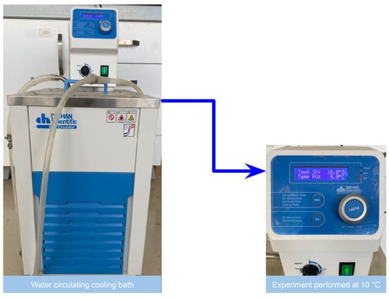
Figure 2.
Water-circulating cooling bath with battery capacity experiment at 10 °C.
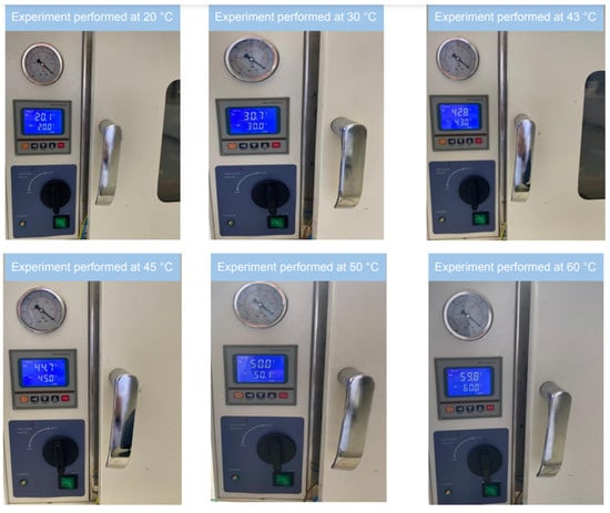
Figure 3.
Battery capacity experiments at different temperatures using a drying oven.
Discharging at 1C at eight different temperature values was carried out with the DL24P discharge device, and the results are given in Figure 4. Different batteries were used at each temperature, and the tests were started after the batteries were discharged at 1C and charged at 1C as they left the factory.
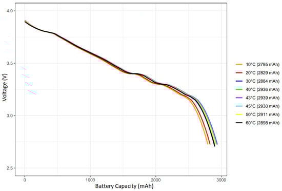
Figure 4.
Battery capacity test at 1C charging current at different temperatures.
Figure 4 shows that the highest capacity value was observed at 43 °C. Considering battery heating during the use of EVs, the battery operating temperature was determined to be between 0 °C and 45 °C. The reason for setting the battery temperature in this range is that if the battery goes out of the ideal operating range, the charging current to be obtained from the energy obtained from regenerative braking will be directed to the SC instead of the battery. Using batteries for charging at low or high temperatures causes permanent capacity losses in the battery [17]. Considering the results obtained experimentally, although the Aspilsan company states that this model battery can operate up to 60 °C in the catalog of use, the temperature is limited to 45 °C to prevent the temperature increase caused by regenerative braking in the battery within the scope of this study.
2.2. Battery Charging Current
A factor affecting both the battery capacity and battery life is the determination of the values between which the battery charging current will be. The charging or discharging rates in the batteries are symbolized by C, and this rate is defined as, for example, the ability of a 1 Ah battery to maintain a current of 1 A for 1 h. Discharge processes at different values of the Li-ion battery were performed experimentally. In this way, the limits of the discharge current to be used in the fuzzy logic controller were determined. The batteries used in the experiment are offered to the user at a 30% discharge rate from the factory. Operating between 4.2 V and 2.5 V voltage values, these batteries were first discharged at 1 C and then charged at 1 C. Discharging at different C ratios was performed at 43 °C with a DL24P discharger capable of discharging between 0.1 A and 30 A. The battery charging current experiments were performed at 43 °C, and the highest capacity was obtained at this temperature (Figure 5).
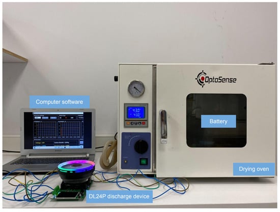
Figure 5.
Discharge experimental setup at 43 °C and different C values.
In this test setup, discharges were performed at C/10, C/5, C/3, C/2, C, 2 C, 3 C, and 5 C ratios. The Aspilsan 18650 NMC battery used in this study has a capacity of 2900 mAh. This capacity value of the battery means that it can meet 2.9 A for 1 h. While charging and discharging processes have a positive effect on the battery’s capacity at low C rates, at high C rates, some of the energy is converted into heat and causes capacity loss on the battery. The evolution of the capacity as a function of the discharge rate is given in Figure 6.
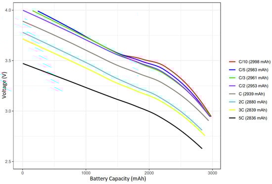
Figure 6.
Battery capacity test at 25 °C at different C ratios.
The battery capacity decreased by around 5% of its capacity when the C ratios increased from C/10 to 5 C, while the heating increased from 43.2 to 93.6 °C (Figure 7). The breaking point of the heat increases is observed above 0.5 C. At high C ratios, some of the energy during the charge/discharge process is converted into heat energy, decreasing the battery capacity.
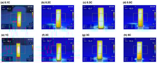
Figure 7.
Evolution of the battery temperatures during the isothermal discharge at 43 °C with different C ratios.
In a fuzzy logic controller, the battery parameters used in an EV and the proposed SC parameters are needed to determine the constraints. The EV battery and motor parameters used to determine the constraints are given in Table 1.

Table 1.
EV battery and motor parameters.
There are 95 series-connected battery cells and 48 parallel-connected battery cells in the EV battery pack. With a motor power of 160 kW, the maximum current to be drawn from the battery cell of the EV is 8.7 A. The maximum current value to be drawn from the battery cell corresponds to the 3 C ratio. Formulas (1)–(4) are calculated for transferring the power gained from regenerative braking to the HESS. (1) is the moment of inertia, (2) is the aerodynamic drag resistance force, (3) is the rolling resistance force, and (4) is the power transferred to the HESS.
where is the rim weight (kg), is the rim radius (m), is the wheel weight (kg), and is the tire sidewall thickness (m).
where is the air density (kg·m3), is the drag coefficient, is the vehicle front surface area, and is the speed (km/h).
where is the rolling coefficient, is the weight coefficient on the front axle, is the total weight (kg), and is the gravity acceleration (m/s2).
where is the motor-generator efficiency ratio, is the transfer rate, is the transfer efficiency, is the axle efficiency, is the variable acceleration (m/s2), is the regenerative braking coefficient, is the coefficient of braking friction, is the motor-generator moment of inertia (kg.m2), and is the power transferred to the hybrid storage system (kW).
Based on these formulas, the energy to be obtained from regenerative braking can be calculated; however, since this energy varies continuously depending on the road condition in EVs, certain scenarios should be determined first. In the first scenario, it is assumed that the vehicle is traveling at 120 km/h and brakes for 12 s after noticing the red lights. Because there is no slope in this scenario, the energy that the EV will obtain from regenerative braking can be calculated by calculating the kinetic energy. First, using the aerodynamic drag resistance force (2), we calculated that the vehicle consumes 5.25 kWh of energy against the drag resistance. The rolling resistance (3) for dry ground is calculated as 15.22 kWh. The kinetic energy of the EV at 120 km/h is 0.316 kWh. In addition to this kinetic energy, the kinetic energy of wheel rotation must be added. The tire size of the EV used in the study is 235/50/19, and the total tire weight is 30 kg. Based on this data, the total rotational kinetic energy for the four wheels is 0.25 kWh. Thus, the total regenerative braking energy will be 0.566 kWh. The regenerative braking energy for EVs with 80% drivetrain efficiency [48] would be 0.452 kWh. A total of 1627.2 kJ of energy would be stored within the vehicle’s total braking time of 12 s. This will result in a peak power of 108.480 kW. With 80% powertrain efficiency in the vehicle, the peak power value will be 86.784 kW. If this power is divided first by the total battery voltage of 400 V and then by 48 parallel-connected battery cells, a charging current value of 4.52 A per cell will be found. This value corresponds to 1.558 C (4.52/2.9 = 1.558) for a 2900 mAh capacity battery.
In the second scenario, a vehicle traveling at 50 km/h is assumed to be driving in the city. In this drive, 0.0756 kWh of energy will be stored during a full stop, and 0.065 kWh of energy will be recovered from regenerative braking with 80% powertrain efficiency. This complete stop will require 5 s of braking. Repeated 100 times for 100 km of city driving, a total of 6.5 kWh of energy will be stored. For an EV with 16.7 kWh energy consumption per 100 km, this energy will provide a gain of 38.9 km. In this scenario, 197.9 kJ of energy will generate a charging current of 2.061 A per battery cell. This value corresponds to 0.710 C for a 2900 mAh capacity battery.
In the last scenario, the regenerative braking energy that will occur when the vehicle descends from 650 m above sea level to sea level is calculated. Considering the total road length of 15 km, the road slope will be 4.33%. Assuming that the vehicle descends this slope at a speed of 80 km/h, 0.26 kWh of energy will be gained. If this process is repeated five times along the road, a total of 1.3 kWh of energy will be recovered from regenerative braking. In this scenario, a charging current of 2.27 A per battery cell will be generated. This corresponds to a value of 1.277 C for a 2900 mAh capacity battery. In all these scenarios, the vehicle weight and the driver were calculated. Changing the weight of the vehicle causes the regenerative braking energy to change. In this case, the charging current value of the energy gained at different loads to the battery cell is given in Table 2. The weight of a passenger is assumed to be 80 kg in the calculations.
Table 2.
Energy gained from regenerative braking under different loads.
In the calculations made under different road conditions and different loads from the three scenarios developed, the charging current gained by regenerative braking to the EV battery cell reached a high charging current value with a C value of 2.275. Low C rates during battery charging increase the battery capacity and battery life. In this context, the SC will be preferred primarily for energy storage from regenerative braking. As soon as the instantaneous average consumption exceeds 16.9 kWh, the SC discharges the load by feeding the electric motor. Thus, the SC will remain empty continuously. When the SC is full, if the temperature and SoC values are suitable for the battery, charging by limiting the charging current value by 0.5 C will improve the battery life. If the SC is full of the battery and is not suitable for energy storage, safe deceleration or stopping will be achieved by mechanical braking. In the current applications to preserve battery life, the efficiency of the energy to be stored is lower than that of the method used in this study because of the lack of a HESS.
Considering all these scenarios, the SC capacity was calculated to optimally store the energy gained from regenerative braking. The capacity of a Maxwell brand BCAP0350 model 350 F SC is 0.354 Wh. The SC pack voltage is 400 V, equivalent to the battery pack voltage, and consists of 150 series connections. To store the energy from regenerative braking and to direct the peak current value during braking to the SC, three parallel connections are considered appropriate. In this case, the total capacity of 450 SCs is 159.3 Wh.
When using two SC packs connected in parallel, a capacity of 106.2 Wh is obtained. This capacity value can store 23.49% of the braking of Scenario 1 with only the driver in the vehicle. This may cause us to recharge the battery with high current values without being able to sufficiently transfer the high current values at the beginning of the braking to the SC. Therefore, the number of SCs is set to 450. Thus, at maximum regenerative braking, 35.24% of the energy will be transferred to the SC, and high current values will be prevented from damaging the battery. The parameters of the Maxwell brand BCAP0350 model 350 F SC are given in Table 3.
Table 3.
Parameters of the Maxwell SC model BCAP0350.
The continuous maximum current value of the SC is 170 A. In all calculated scenarios, a maximum charging current of 92.38 A will be obtained for 150 series and three parallel-connected SC cells. In this case, safe storage will be provided without exceeding the maximum current of the SCs.
2.3. Battery and Supercapacitor State-of-Charge
For the batteries to charge/discharge healthily, they must be operated within a certain SoC range. When the studies in the literature are examined, it is seen that the most efficient operating SoC range of Li-ion batteries is 20–90% [49]. In this context, charge/discharge operations at low and high SoC values increase the stress on the battery [50]. SCs can charge and discharge very quickly [51]. Moreover, because of their high power density, SCs can cater to the sudden acceleration demands in EVs. In addition, the cycle life of SCs is more than 1 million [52]. Because of their high cycle life, they can be operated in a wider SoC range than batteries. Similarly, their operating temperatures are also wider than those of Li-ion batteries. In this way, SCs are preferred in applications that require a continuous charge/discharge, such as regenerative braking. SCs can be operated in the 5–95% SoC range to achieve high efficiency from their energy density [53,54].
3. Design of Fuzzy Logic System
3.1. Data Preparation
A fuzzy logic control system has four inputs, namely temperature, charging current, battery SoC, and SC SoC, and two outputs, namely the battery transfer ratio and SC transfer ratio. The boundary ranges of these inputs were determined by the experimental studies, and a dataset of 1000 units was created. Table 4 shows the data entered into the “Matlab® Fuzzy Logic” system. The main objective is to prolong the battery life by maintaining battery health by directing energy from regenerative braking to the SC under high temperatures, high charging currents, and high battery SoC conditions.
Table 4.
Fuzzy logic dataset.
3.2. Building the Model
There are some reasons for choosing the membership functions and the type of modeling in fuzzy logic. In complex systems such as HESS, it is important to have the ability to model the complex interactions of various input variables. Trapezoidal membership functions better handle the complexities of such systems, providing flexibility and helping to make clearer decisions in uncertain situations. Therefore, the membership functions for the inputs defined in the fuzzy logic control system are characterized as trapezoidal ‘trapmf’ shaped. In terms of the modeling type in fuzzy logic, there are two different approaches. These are Sugeno-type modeling and Mamdani-type modeling. While Sugeno-type modeling is mainly used to create and analyze a mathematical model of uncertain systems, Mamdani-type modeling is preferred for creating and interpreting fuzzy logic rule sets using natural language expressions. The Sugeno-type modeling method was chosen in order to define the energy transfer rates of batteries and SCs more clearly. In addition, the Sugeno modeling method is more successful than the Mamdani modeling method in explaining non-linear relationships, such as in the HESS, clarity of outputs, and ease of mathematical analysis. Therefore, the Sugeno-type modeling method was chosen for a clearer description of the battery and SC transfer rates. Table 5 provides the boundary points of the membership functions. In this table, the input levels are expressed as low (L), nominal (N), and high (H).
Table 5.
Fuzzy logic control system’s membership functions.
The boundary points provided in Table 5 were determined on the basis of the experiments conducted. The representation of the membership functions for these boundary points in the Matlab program is illustrated in Figure 8.
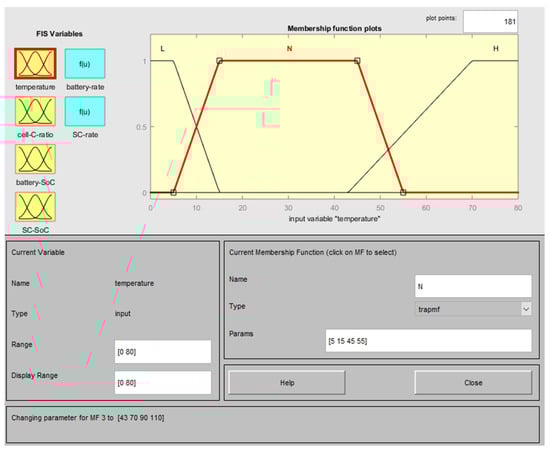
Figure 8.
Membership functions related to the battery temperature.
After the membership functions for all the input values were created according to the specified boundary values, 800 data points were entered for the training phase in the ANFIS environment. Based on these data, ANFIS generated 81 rules. These rules are shown in Figure 9, and the interval variables associated with them are shown in Figure 10.
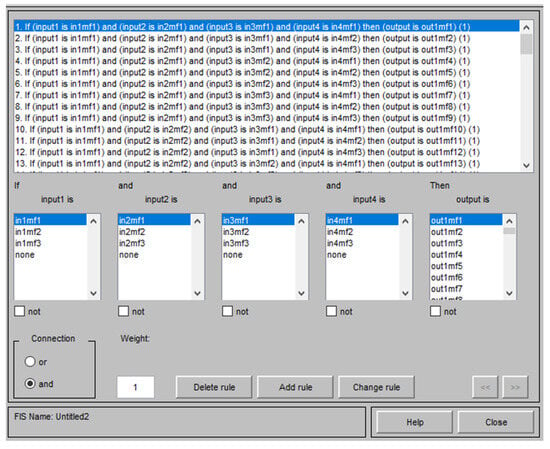
Figure 9.
ANFIS rule table.

Figure 10.
ANFIS rule output values.
A total of 800 data were used in the training phase, while the remaining 100 data were used in the testing phase, and 100 data were used in the validation phase. In the results obtained using the ANFIS method, the model achieved very successful learning and could make decisions with high accuracy rates. The performance of the model with the test data is given in Table 6. The fact that the R2 value is close to 1 and the MSE and RMSE values are close to 0 indicates the success of the model. The connection between the input variables of the model is shown in three dimensions in Figure 11.
Table 6.
Performance evaluation of the model.
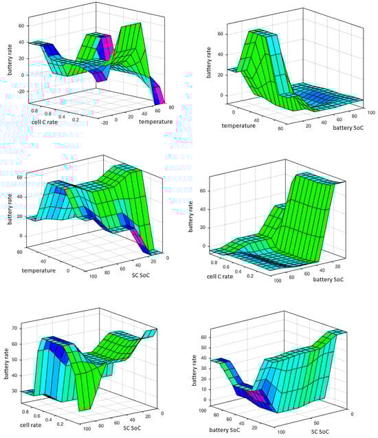
Figure 11.
Three-dimensional relationship between input variables in the model.
Another important feature of the model is the switching between the battery and SC. The output results can be battery-only, SC-only, or the HESS with different ratios. In the case of battery-only or SC-only, routing must be provided by switching. Similarly, in the case of the HESS, the third switch should be used, and the connection between the battery and SC should be disconnected. This is because the internal resistance of the SC is much smaller than that of the Li-ion battery. Therefore, if the SC SoC ratio is lower than the battery SoC ratio, the SC may pull the load on the battery. A third switch is needed to prevent this situation. In addition, thyristors should be used to provide energy storage at different rates in the HESS. For this storage at variable rates, storage can be provided by changing the trigger angle of the thyristor. This ensures frequency matching between these two storage methods. The HESS can quickly draw energy from the SCs to stabilize momentary power fluctuations while turning to the batteries for longer-term energy needs [55]. In this way, the power stability and performance of the vehicle are ensured while at the same time ensuring that the batteries last longer and are protected from constant overloading or discharging.
4. Simulation and Analysis
In this study, the NEDC’s cycle is simulated, which is close to real-world driving. The NEDC is a standardized test procedure in a laboratory environment and is used to measure the fuel consumption and emissions of vehicles. However, in real-world conditions, the performance, fuel consumption, and emissions of vehicles can often differ from the NEDC test results. The reasons for this are traffic, vehicle aging, weather conditions, and driver behavior. In this study, we minimized this difference by simulating vehicle aging (battery) and different weather conditions in the simulation environment. However, some differences may still occur due to driver behavior. Furthermore, the NEDC’s drive cycle used in this study includes traffic density and congested traffic conditions in the cycle. In this way, the data obtained takes into account urban, suburban, and congested road conditions.
4.1. ADVISOR Simulation Environment
The ADVISOR program was developed by the National Renewable Energy Laboratory (NREL) in the late 1990s [56]. The ADVISOR program is used in the analysis of conventional, hybrid, and EVs. Since it is an open-source software, many researchers have contributed to the program’s library. In addition, because it works as a Matlab Simulink module, it offers the flexibility to create a control strategy. ADVISOR makes agreements with commercial automobile manufacturers and universities to ensure that the algorithms reach minimum uncertainty. There are 59 different driving configurations in the program. Each configuration parallels real-life situations and is recognized by international institutions [57].
In this paper, the proposed HESS and conventional storage system are designed in the ADVISOR program. The designed fuzzy logic controller is integrated into the HESS and analyzed. Before the blog diagram is created, the researcher is first presented with the vehicle data entry screen in the ADVISOR program. On this screen, the researcher enters the relevant data and is transferred to the next stage, the blog diagram design.
Based on the data entered on the vehicle data entry screen, a blog diagram is automatically created for the EV, while a new blog diagram is created for the HESS. In the automatically generated diagram, data can be obtained from all the important units of the EV, such as the brakes, wheels, engine, and battery. In the HESS, the battery and SC are connected in parallel, and a fuzzy logic controller is added as the control system. Figure 12 shows the blog diagram of the EV, and Figure 13 shows the blog diagram of the EV with the hybrid storage system.
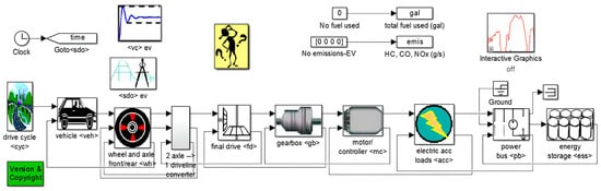
Figure 12.
EV’s blog diagram.
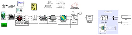
Figure 13.
Blog diagram of an EV with HESS.
Among the driving cycles in the ADVISOR program, the two cycles most frequently used by automobile manufacturers are the New European Driving Cycle (NEDC) and the Worldwide Harmonised Light Vehicle (WLTC) [58]. The NEDC cycle was preferred until 2018, but the WLTC cycle was switched to WLTC driving because fuel consumption in conventional vehicles was lower in this cycle than in real life [59]. The WLTC driving cycle was deemed unsuitable for this study because of the excessive regenerative braking. The NEDC driving cycle includes both urban and non-urban data. The amount of regenerative braking is more in line with real driving. Figure 14 shows the speed–time graph of the NEDC cycle.
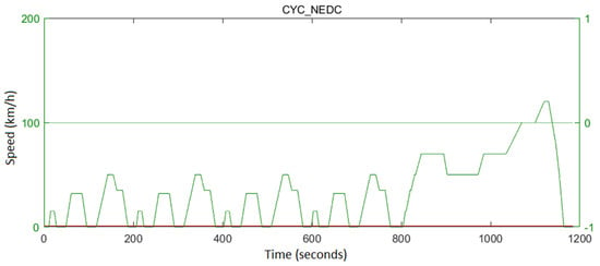
Figure 14.
NEDC driving cycle.
The NEDC driving cycle is carried out at an ambient temperature ranging from 20 °C to 30 °C and a driving cycle distance of 10.93 km. The maximum speed during the cycle is 120 km/h, and the average speed is 33.21 km/h. In addition, the total duration of this drive is 1184 s, and the maximum acceleration is 1.06 m/s2. The majority of driving occurs within the city (Figure 14). Because this driving cycle includes both urban and non-urban driving, it is a suitable driving technique for EVs in terms of application. Figure 15 shows the speed ratios of the driving cycle in percentages.
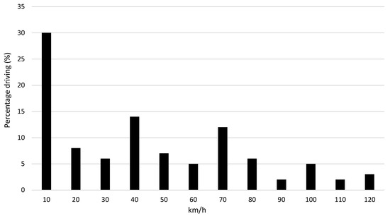
Figure 15.
Vehicle speed percentiles used in the NEDC driving cycle.
In the simulation environment, the vehicle’s road conditions in Europe (NEDC) were simulated, and the current values drawn from the battery and HESS were analyzed. The negative values represent the charging current from regenerative braking, and the positive values represent the current drawn from the battery during the driving cycle. The current values are calculated as the C value per battery and are given in Figure 16. When the current values drawn from the battery and the current values from regenerative braking are analyzed, the battery in the HESS is exposed to 29.1% lower current values than the battery storage system. This will contribute to the battery’s health and help the battery to be used longer.
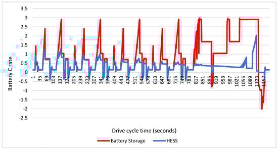
Figure 16.
Current values in the NEDC driving cycle in the ADVISOR program.
The ADVISOR program does not support a SC storage system. However, by modifying the blog diagram, testing can be performed by defining the SC catalog data as a battery. The test starts at 70% SoC and 70% SC SoC in the NEDC drive cycle. The HESS completed the driving cycle with a 7.28% battery loss, whereas the battery storage system completed the driving cycle with a 15.64% battery loss. When the test results are analyzed, it is seen that the fuzzy logic controller makes a positive contribution to the average energy consumption with the SC. Figure 17 shows the SoC change in the systems during the drive cycle.
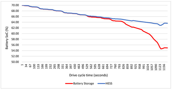
Figure 17.
Battery SoC replacement in NEDC driving cycle in ADVISOR program.
In simulation tests performed in the ADVISOR program, it is not possible to change the outdoor temperature. In addition, the program does not allow the determination of the internal resistance of the battery and the change in the battery SoC value at the beginning of the test. Due to these limitations of the program, simulations were also performed and compared with the Siemens Simcenter Flomaster program, which has more advanced features.
4.2. Siemens Simcenter Flomaster Simulation Environment
This program provides more possibilities than the ADVISOR program in changing the motor, battery, and outdoor parameters. It can also be integrated with the Matlab program. In this way, the fuzzy logic controller was integrated into the system, and driving cycles were realized. Values are defined for 40 different components used in the modeling and the properties of these components. While the model for the EV is created automatically in line with the data entered on the vehicle data entry screen, the EV battery model is designed for the hybrid storage system. In this model, data can be obtained from all units of the EV, such as the brakes, wheels, engine, and battery. In the HESS, the battery and SC are connected in parallel and a fuzzy logic controller is integrated as the control system. Figure 18 shows the EV blog diagram modeled in the Simcenter Flomaster program.
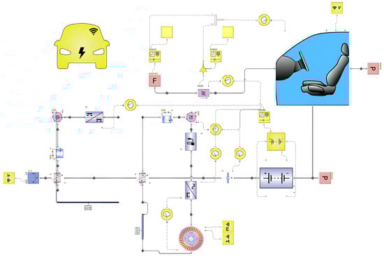
Figure 18.
EV control blog diagram modeled in the Simcenter Flomaster program.
In this program, outdoor and in-cabin temperatures can be adjusted to obtain the closest-to-reality results on battery usage values. It also allows changes to the battery’s initial SoC and battery capacity. The Simcenter Flomaster program allows customization of all battery parameters. In this context, it creates an internal resistance model, which is the most important variable for battery health. The three-dimensional relationship of the internal resistance created in the program for the battery used in this study is shown in Figure 19.
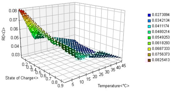
Figure 19.
Internal resistance changes depending on battery temperature and SoC in the Simcenter Flomaster program.
In the simulation environment, the vehicle’s road conditions in Europe (NEDC driving cycle) were simulated at different outdoor temperatures and different battery SoC values, and then the current values that passed through the battery and HESS were examined. The battery data of the EV that was modeled in the simulation is defined as 4560 battery units with 95 series and 48 parallel connections. In this study, 2900 mAh batteries were tested at −10 °C, 0 °C, 10 °C, 20 °C, 20 °C, 30 °C, 40 °C, and 50 °C outdoor temperatures. At all these outdoor temperatures, the EV cabin temperature was kept constant at 20 °C. The current values obtained from the Simcenter Flomaster program at a 20 °C outdoor temperature are calculated as the C value per battery (Figure 20). The regenerative braking rate was defined as 80%, and the battery’s initial SoC was defined as 70%. When the current values through the battery and the current values from regenerative braking are analyzed, the battery in the hybrid storage system is exposed to 28.7% lower current values than the battery storage system.
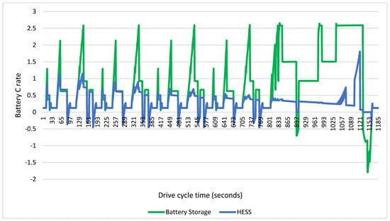
Figure 20.
Current values in the NEDC driving cycle in the Simcenter Flomaster program.
The Simcemter Flomaster program was tested at a 70% battery charge and a 50% SC charge. The hybrid storage system completed the driving cycle with a 4.15% battery loss, whereas the battery storage system completed the driving cycle with a 5.02% battery loss. Figure 21 shows the SoC change in the systems during the driving cycle. Figure 22 shows the battery SoC values obtained after the driving cycle at a 20 °C outdoor temperature and different SoC values of the battery.
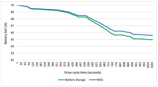
Figure 21.
Battery SoC replacement in NEDC driving cycle in Simcenter Flomaster program.
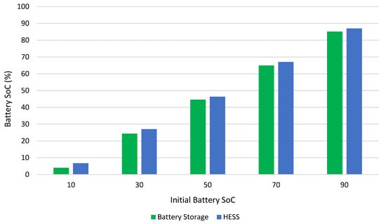
Figure 22.
Battery variation at different SoC values.
Different percentage gains were obtained by starting the driving cycle with different SoC ratios of the battery. This is because fuzzy logic protects the battery’s health by selecting different storage methods at different SoC ratios. The same is true for different temperature values. Figure 23 shows the battery SoC values obtained because of the driving cycle at 70% battery and a 50% SC SoC ratio and different outdoor temperatures.
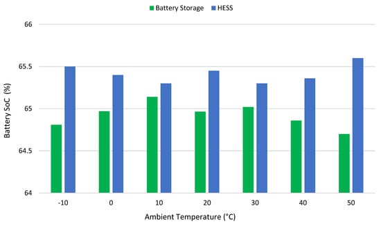
Figure 23.
Battery SoC obtained at different temperatures.
When the battery SoC was 10%, the system used the SC more to prevent the battery from deep discharging. When the battery SoC is 90%, a similar situation is realized, and the battery is prevented from creating a security weakness by charging to full capacity. Considering all the different SoC values, the battery consumed 20.43% less energy in the HESS. The battery utilization rate also changed with the change in outdoor temperature, and the battery utilization rate decreased by 21.3% in the tests performed at six different outdoor temperatures. When the outdoor temperature was 50 °C, the battery SoC increased as the system reduced its battery usage. Because of the reduced battery utilization, the heat generated by the battery pack is reduced, and the energy consumption for cooling is reduced. Figure 24 shows the heat energy generated by the battery pack during the driving cycle at 70% battery, a 50% SC SoC, and a 20 °C outdoor temperature.
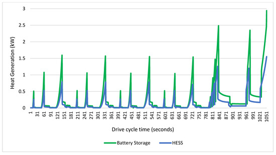
Figure 24.
Heat generation of the battery in the NEDC driving cycle (kW).
The HESS produced 46.84% less heat than the standard battery system during the NEDC driving cycle. Thus, the battery’s health was preserved by preventing the increase in internal resistance that would occur in the battery because of battery heating. Thus, the HESS contributed positively to both the vehicle range and battery life. During the driving cycle, the range of the EV without regenerative braking with battery storage was 218 km, 235 km with only regenerative braking, and 243 km with a combination of regenerative braking and hybrid storage. Thus, both the range of the EV has increased and the battery life has been positively contributed to due to less battery use.
5. Results and Discussion
The comparison of the HESS controlled by fuzzy logic with the battery storage system was carried out in the ADVISOR and Simcenter Flomaster programs. The NEDC driving cycle was used in the simulations, and the current values on the battery and battery SoC were compared. Although SCs lack a high energy density, they quickly store the instantaneous energy demands from regenerative braking and quickly meet the instantaneous energy demands during sudden acceleration. In this way, the consumption values on the battery were reduced and the battery’s health was maintained by reducing the high current values in the energy stored and consumed from regenerative braking on the battery. Figure 25 shows the current values generated on the battery by the HESS in ADVISOR and Simcenter Flomaster programs.
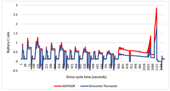
Figure 25.
Comparison of the current values generated by the HESS on the battery.
The ADVISOR program, on the other hand, starts the battery’s initial SoC value with only 70%. For this reason, the tests of the battery at different SoC values were performed using the Simcenter Flomaster program. In addition, tests at different outdoor temperatures and heat generation values of the battery were performed using the Simcenter Flomaster program. In the EV with the HESS, the current values on the battery decreased by 29.1% in the ADVISOR program and 28.7% in the Simcenter Flomaster program. Similarly, the battery SoC values decreased by 7% in the ADVISOR program and 4.15% in the Simcenter Flomaster program.
Martyushev et al. [60] reduced the energy consumption by 5% by optimizing the power distribution between the SCs and batteries in composite energy storage systems. Furthermore, the energy efficiency was increased from 4.1% to 6.7% by optimizing the parameters of the flywheel device and the energy management strategy. As a result of their simulation study, Song et al. [61] argued that the total cost of the HESS during a 10-year operation, including capital costs, electricity costs, and battery replacement costs, is 25.9% less than current battery prices. Da Silva et al. [62] developed a multi-objective optimization dual HESS and achieved a 19.57% range increase and 22.88% battery life extension compared to a single HESS-equipped EV. In the existing literature studies, a HESS system based on a regenerative braking system is quite scarce. In this study, simulations in the ADVISOR and Siemens Simcenter Flomaster programs show that the HESS is effective in maintaining the battery’s health and optimizing energy consumption, especially in regenerative braking situations. The integration of SCs in the storage and utilization of the battery contributes to a significant reduction in average energy consumption, an increase in vehicle range, and the preservation of battery health. This study provides more comprehensive results than other studies by presenting a comprehensive analysis with tests performed over a wide temperature range and data obtained at different SoC values.
6. Conclusions
There has been a marked increase in the popularity of EVs, driven by growing environmental concerns and market demand. However, electrochemical energy storage systems are not yet competitive with fuel-based vehicles. One of the main reasons is the limited lifetime of battery systems, which necessitates a redesign of the energy storage systems. In this context, SCs in the HESS offer a solution for batteries that are weak. However, the installation of battery/SC systems is more complex than the integration of two different electrochemical power sources. The timing of the charging or discharging of each electrochemical cell is an important factor that needs to be carefully managed. This requires a complex handling procedure, which is different from the regular testing of electrochemical cells. This study aims to attract the interest of various researchers and focus on the design of local battery/SC systems, especially for EVs. In this direction, an energy storage system is designed by evaluating the performance of the battery at different temperatures, SoCs, and currents using a fuzzy logic controller.
This study highlights the potential of the HESS to enhance the battery performance in EVs. The research results underscore the remarkable effectiveness of the HESS in bolstering EV performance, concurrently ensuring battery longevity and optimizing energy usage. In simulated NEDC driving cycles using both the ADVISOR and Siemens Simcenter Flomaster programs, the HESS showcased significant reductions in battery capacity loss. Specifically, the HESS demonstrated a remarkable 7.28% reduction in loss compared to the battery storage system’s 15.64% in the ADVISOR program and a notable 4.15% loss compared to the system’s 5.02% in the Siemens Simcenter Flomaster program. Furthermore, the HESS contributed substantially to reducing on-battery currents by 29.1% in the ADVISOR program and 28.7% in the Siemens Simcenter Flomaster program. These reductions effectively alleviate high current stresses on the battery. Temperature variations also played a crucial role, with tests conducted in the Siemens Simcenter Flomaster program revealing a significant 21.3% reduction in the average battery utilization rate. Moreover, during the NEDC drive cycle, the HESS demonstrated a noteworthy 46.84% reduction in heat generation within the battery. The HESS played an instrumental protective role by preventing temperature rises and mitigating the increase in internal resistance, thereby positively contributing to the battery’s life and health. Additionally, tests conducted at various SoC values revealed an average energy consumption reduction of 20.43% with the implementation of the HESS. Remarkably, during the NEDC driving cycle, the integration of the HESS led to a notable 3.4% increase in driving range compared to traditional battery storage systems. This underscores the significant potential of the HESS in extending EVs operational distances, offering tangible benefits to users while enhancing an overall efficiency and sustainability in transportation. In summary, these findings affirm that the HESS significantly enhances the EV’s performance while preserving its battery life and optimizing energy consumption. The widespread adoption of the HESS is poised to drive down energy consumption in EVs, accelerating countries’ efforts to achieve their carbon emission reduction targets effectively and expeditiously.
Author Contributions
Conceptualization, M.Ş. and M.Ö.; Methodology, M.Ş. and Y.R.E.; Investigation, M.Ş.; Resources, M.Ö. and Y.R.E.; Data curation, M.Ş.; Writing—original draft, M.Ş. and Y.R.E.; Writing—review and editing, M.Ö. and Y.R.E.; Visualization, M.Ş.; Supervision, M.Ö. and Y.R.E.; Project administration, M.Ö. and Y.R.E. All authors have read and agreed to the published version of the manuscript.
Funding
This research received no external funding.
Institutional Review Board Statement
Not applicable.
Informed Consent Statement
Not applicable.
Data Availability Statement
The data used to support the findings of this study are included within the article.
Acknowledgments
The authors acknowledge the support of the Konya Necmettin Erbakan University (NEU) Science and Technology Research and Application Center (BITAM).
Conflicts of Interest
The authors declare no conflicts of interest.
References
- Executive Summary—Global EV Outlook 2022—Analysis. IEA. Available online: https://www.iea.org/reports/global-ev-outlook-2022/executive-summary (accessed on 26 February 2024).
- Global EV Market Share. Statista. Available online: https://www.statista.com/statistics/1371599/global-ev-market-share/ (accessed on 26 February 2024).
- Xu, B.; Sharif, A.; Shahbaz, M.; Dong, K. Have Electric Vehicles Effectively Addressed CO2 Emissions? Analysis of Eight Leading Countries Using Quantile-on-Quantile Regression Approach. Sustain. Prod. Consum. 2021, 27, 1205–1214. [Google Scholar] [CrossRef]
- Road Freight Global Pathways Report. Available online: https://www.mckinsey.com/industries/automotive-and-assembly/our-insights/road-freight-global-pathways-report (accessed on 25 March 2024).
- Prospects for Electric Vehicle Deployment. Available online: https://www.iea.org/reports/global-ev-outlook-2023/prospects-for-electric-vehicle-deployment (accessed on 25 March 2024).
- The Paris Agreement. Available online: https://unfccc.int/process-and-meetings/the-paris-agreement (accessed on 26 February 2024).
- Ishaque, M.R.; Khan, M.A.; Afzal, M.M.; Wadood, A.; Oh, S.-R.; Talha, M.; Rhee, S.-B. Fuzzy Logic-Based Duty Cycle Controller for the Energy Management System of Hybrid Electric Vehicles with Hybrid Energy Storage System. Appl. Sci. 2021, 11, 3192. [Google Scholar] [CrossRef]
- Alanazi, F. Electric Vehicles: Benefits, Challenges, and Potential Solutions for Widespread Adaptation. Appl. Sci. 2023, 13, 6016. [Google Scholar] [CrossRef]
- Yang, H.; Fulton, L. Decoding US Investments for Future Battery and Electric Vehicle Production. Transp. Res. D Transp. Environ. 2023, 118, 103693. [Google Scholar] [CrossRef]
- Deng, J.; Bae, C.; Denlinger, A.; Miller, T. Electric Vehicles Batteries: Requirements and Challenges. Joule 2020, 4, 511–515. [Google Scholar] [CrossRef]
- Lee, G.; Song, J.; Han, J.; Lim, Y.; Park, S. Study on Energy Consumption Characteristics of Passenger Electric Vehicle According to the Regenerative Braking Stages during Real-World Driving Conditions. Energy 2023, 283, 128745. [Google Scholar] [CrossRef]
- Kashkanov, A.; Semenov, A.; Kashkanova, A.; Kryvinska, N.; Palchevskyi, O.; Baraban, S. Estimating the Effectiveness of Electric Vehicles Braking When Determining the Circumstances of a Traffic Accident. Sci. Rep. 2023, 13, 19916. [Google Scholar] [CrossRef] [PubMed]
- Bautista-Montesano, R.; Galluzzi, R.; Mo, Z.; Fu, Y.; Bustamante-Bello, R.; Di, X. Longitudinal Control Strategy for Connected Electric Vehicle with Regenerative Braking in Eco-Approach and Departure. Appl. Sci. 2023, 13, 5089. [Google Scholar] [CrossRef]
- Chidambaram, R.K.; Chatterjee, D.; Barman, B.; Das, P.P.; Taler, D.; Taler, J.; Sobota, T. Effect of Regenerative Braking on Battery Life. Energies 2023, 16, 5303. [Google Scholar] [CrossRef]
- Saiteja, P.; Ashok, B.; Wagh, A.S.; Farrag, M.E. Critical Review on Optimal Regenerative Braking Control System Architecture, Calibration Parameters and Development Challenges for EVs. Int. J. Energy Res. 2022, 46, 20146–20179. [Google Scholar] [CrossRef]
- Liu, H.; Lei, Y.; Fu, Y.; Li, X. Multi-Objective Optimization Study of Regenerative Braking Control Strategy for Range-Extended Electric Vehicle. Appl. Sci. 2020, 10, 1789. [Google Scholar] [CrossRef]
- Keil, P.; Jossen, A. Aging of Lithium-Ion Batteries in Electric Vehicles: Impact of Regenerative Braking. World Electr. Veh. J. 2015, 7, 41–51. [Google Scholar] [CrossRef]
- Kouchachvili, L.; Yaïci, W.; Entchev, E. Hybrid Battery/Supercapacitor Energy Storage System for the Electric Vehicles. J. Power Sources 2018, 374, 237–248. [Google Scholar] [CrossRef]
- Sowe, J.; Varela Barreras, J.; Schimpe, M.; Wu, B.; Candelise, C.; Nelson, J.; Few, S. Model-Informed Battery Current Derating Strategies: Simple Methods to Extend Battery Lifetime in Islanded Mini-Grids. J. Energy Storage 2022, 51, 104524. [Google Scholar] [CrossRef]
- Zhang, L.; Sun, C.; Cai, G.; Koh, L.H. Charging and Discharging Optimization Strategy for Electric Vehicles Considering Elasticity Demand Response. eTransportation 2023, 18, 100262. [Google Scholar] [CrossRef]
- Zhang, M.; Liu, Y.; Li, D.; Cui, X.; Wang, L.; Li, L.; Wang, K. Electrochemical Impedance Spectroscopy: A New Chapter in the Fast and Accurate Estimation of the State of Health for Lithium-Ion Batteries. Energies 2023, 16, 1599. [Google Scholar] [CrossRef]
- Dai, Q.; Kelly, J.C.; Gaines, L.; Wang, M. Life Cycle Analysis of Lithium-Ion Batteries for Automotive Applications. Batteries 2019, 5, 48. [Google Scholar] [CrossRef]
- Garniwa, I.; Orlando, G.; Noorfatima, N.; Sudiarto, B.; Dipantara, B. Study of Battery Performance Analysis with Regenerative Braking Methods Using SIMULINK. J. Phys. Conf. Ser. 2019, 1376, 012027. [Google Scholar] [CrossRef]
- Salek, F.; Resalati, S.; Babaie, M.; Henshall, P.; Morrey, D.; Yao, L. A Review of the Technical Challenges and Solutions in Maximising the Potential Use of Second Life Batteries from Electric Vehicles. Batteries 2024, 10, 79. [Google Scholar] [CrossRef]
- Manzetti, S.; Mariasiu, F. Electric Vehicle Battery Technologies: From Present State to Future Systems. Renew. Sustain. Energy Rev. 2015, 51, 1004–1012. [Google Scholar] [CrossRef]
- Li, J.; Du, Z.; Ruther, R.E.; An, S.J.; David, L.A.; Hays, K.; Wood, M.; Phillip, N.D.; Sheng, Y.; Mao, C.; et al. Toward Low-Cost, High-Energy Density, and High-Power Density Lithium-Ion Batteries. JOM 2017, 69, 1484–1496. [Google Scholar] [CrossRef]
- Ahsan, M.B.F.; Mekhilef, S.; Soon, T.K.; Mubin, M.B.; Shrivastava, P.; Seyedmahmoudian, M. Lithium-ion Battery and Supercapacitor-based Hybrid Energy Storage System for Electric Vehicle Applications: A Review. Int. J. Energy Res. 2022, 46, 19826–19854. [Google Scholar] [CrossRef]
- Guo, L.; Hu, P.; Wei, H. Development of Supercapacitor Hybrid Electric Vehicle. J. Energy Storage 2023, 65, 107269. [Google Scholar] [CrossRef]
- Lemian, D.; Bode, F. Battery-Supercapacitor Energy Storage Systems for Electrical Vehicles: A Review. Energies 2022, 15, 5683. [Google Scholar] [CrossRef]
- Chau, K.T.; Wong, Y.S.; Chan, C.C. An Overview of Energy Sources for Electric Vehicles. Energy Convers. Manag. 1999, 40, 1021–1039. [Google Scholar] [CrossRef]
- Owens, B.B.; Osaka, T. Panel Discussion Future Prospects of Lithium Batteries. J. Power Sources 1997, 68, 173–186. [Google Scholar] [CrossRef][Green Version]
- Gutmann, G. Hybrid Electric Vehicles and Electrochemical Storage Systems—A Technology Push–Pull Couple. J. Power Sources 1999, 84, 275–279. [Google Scholar] [CrossRef]
- Lam, L.T.; Louey, R. Development of Ultra-Battery for Hybrid-Electric Vehicle Applications. J. Power Sources 2006, 158, 1140–1148. [Google Scholar] [CrossRef]
- Shukla, A.K.; Aricò, A.S.; Antonucci, V. An Appraisal of Electric Wieczorek Power Sources. Renew. Sustain. Energy Rev. 2001, 5, 137–155. [Google Scholar] [CrossRef]
- Song, Z.; Li, J.; Hou, J.; Hofmann, H.; Ouyang, M.; Du, J. The Battery-Supercapacitor Hybrid Energy Storage System in Electric Vehicle Applications: A Case Study. Energy 2018, 154, 433–441. [Google Scholar] [CrossRef]
- Zhu, T.; Lot, R.; Wills, R.G.A.; Yan, X. Sizing a Battery-Supercapacitor Energy Storage System with Battery Degradation Consideration for High-Performance Electric Vehicles. Energy 2020, 208, 118336. [Google Scholar] [CrossRef]
- Lei, D.; Gao, Y.; Hou, Z.; Ren, L.; Jiang, M.; Cao, Y.; Zhang, Y.; Wang, J.-G. A Superior Lithium-Ion Capacitor Based on Ultrafine MnO/Dual N-Doped Carbon Anode and Porous Carbon Cathode. Batteries 2023, 9, 241. [Google Scholar] [CrossRef]
- Şen, M.; Yiğiter, M.S.; Özcan, M. Why Are Consumers Switching to Electric Vehicles? Analyzing Consumers Preferences for Electric Vehicles. Case Stud. Transp. Policy 2023, 14, 101108. [Google Scholar] [CrossRef]
- Wieczorek, M.; Lewandowski, M.; Jefimowski, W. Cost comparison of different configurations of a hybrid energy storage system with battery-only and supercapacitor-only storage in an electric city bus. Bull. Pol. Acad. Sci. Tech. Sci. 2019, 67, 1095–1106. [Google Scholar] [CrossRef]
- Abdel Maksoud, M.I.A.; Fahim, R.A.; Shalan, A.E.; Abd Elkodous, M.; Olojede, S.O.; Osman, A.I.; Farrell, C.; Al-Muhtaseb, A.H.; Awed, A.S.; Ashour, A.H.; et al. Advanced Materials and Technologies for Supercapacitors Used in Energy Conversion and Storage: A Review. Environ. Chem. Lett. 2021, 19, 375–439. [Google Scholar] [CrossRef]
- Mariasiu, F.; Kelemen, E.A. Analysis of the Energy Efficiency of a Hybrid Energy Storage System for an Electric Vehicle. Batteries 2023, 9, 419. [Google Scholar] [CrossRef]
- Qi, J.; Su, M. Analysis of Micro-Electric Vehicle with Super Capacitor/Battery Hybrid Energy Storage System. J. Phys. Conf. Ser. 2023, 2459, 012091. [Google Scholar] [CrossRef]
- Lahyani, A.; Sari, A.; Lahbib, I.; Venet, P. Optimal Hybridization and Amortized Cost Study of Battery/Supercapacitors System under Pulsed Loads. J. Energy Storage 2016, 6, 222–231. [Google Scholar] [CrossRef]
- Naseri, F.; Karimi, S.; Farjah, E.; Schaltz, E. Supercapacitor Management System: A Comprehensive Review of Modeling, Estimation, Balancing, and Protection Techniques. Renew. Sustain. Energy Rev. 2022, 155, 111913. [Google Scholar] [CrossRef]
- Lakshmi, K.C.S.; Vedhanarayanan, B. High-Performance Supercapacitors: A Comprehensive Review on Paradigm Shift of Conventional Energy Storage Devices. Batteries 2023, 9, 202. [Google Scholar] [CrossRef]
- He, X.; Zhang, X. A Comprehensive Review of Supercapacitors: Properties, Electrodes, Electrolytes and Thermal Management Systems Based on Phase Change Materials. J. Energy Storage 2022, 56, 106023. [Google Scholar] [CrossRef]
- Subramanian, M.; Solomon, J.M.; Raja, V.; Stanislaus Arputharaj, B.; Shaik, S.; Saleel, C.A.; Alwetaishi, M.; Cuce, E. Experimental Studies and Comprehensive Computational Investigations on Composites-Based Phase Change Material for Battery Thermal Management Systems in Electric Vehicles. J. Energy Storage 2024, 82, 110471. [Google Scholar] [CrossRef]
- Berjoza, D.; Pirs, V.; Jurgena, I. Research into the Regenerative Braking of an Electric Car in Urban Driving. World Electr. Veh. J. 2022, 13, 202. [Google Scholar] [CrossRef]
- Gao, Y.; Jiang, J.; Zhang, C.; Zhang, W.; Jiang, Y. Aging Mechanisms under Different State-of-Charge Ranges and the Multi-Indicators System of State-of-Health for Lithium-Ion Battery with Li(NiMnCo)O2 Cathode. J. Power Sources 2018, 400, 641–651. [Google Scholar] [CrossRef]
- Makki, M.; Lee, C.W.; Ayoub, G. Stress Distribution Inside a Lithium-Ion Battery Cell during Fast Charging and Its Effect on Degradation of Separator. Batteries 2023, 9, 502. [Google Scholar] [CrossRef]
- Collath, N.; Tepe, B.; Englberger, S.; Jossen, A.; Hesse, H. Aging Aware Operation of Lithium-Ion Battery Energy Storage Systems: A Review. J. Energy Storage 2022, 55, 105634. [Google Scholar] [CrossRef]
- Şahin, M.E.; Blaabjerg, F.; Sangwongwanich, A. A Comprehensive Review on Supercapacitor Applications and Developments. Energies 2022, 15, 674. [Google Scholar] [CrossRef]
- Rehman, J.; Eid, K.; Ali, R.; Fan, X.; Murtaza, G.; Faizan, M.; Laref, A.; Zheng, W.; Varma, R.S. Engineering of Transition Metal Sulfide Nanostructures as Efficient Electrodes for High-Performance Supercapacitors. ACS Appl. Energy Mater. 2022, 5, 6481–6498. [Google Scholar] [CrossRef]
- Raghavendra, K.V.G.; Vinoth, R.; Zeb, K.; Muralee Gopi, C.V.V.; Sambasivam, S.; Kummara, M.R.; Obaidat, I.M.; Kim, H.J. An Intuitive Review of Supercapacitors with Recent Progress and Novel Device Applications. J. Energy Storage 2020, 31, 101652. [Google Scholar] [CrossRef]
- Daraz, A.; Khan, I.A.; Basit, A.; Malik, S.A.; AlQahtani, S.A.; Zhang, G. Frequency Regulation of Interconnected Hybrid Power System with Assimilation of Electrical Vehicles. Heliyon 2024, 10, e28073. [Google Scholar] [CrossRef]
- Turkmen, A.C.; Solmaz, S.; Celik, C. Analysis of Fuel Cell Vehicles with Advisor Software. Renew. Sustain. Energy Rev. 2017, 70, 1066–1071. [Google Scholar] [CrossRef]
- Mitra, U.; Arya, A.; Gupta, S. Comparative Analysis of Hybrid Electric Vehicle on Different Performance Metrics Using ADVISOR 2.0. In Power Engineering and Intelligent Systems; Lecture Notes in Electrical Engineering; Springer Nature Singapore: Singapore, 2024; pp. 153–167. [Google Scholar]
- Sileghem, L.; Bosteels, D.; May, J.; Favre, C.; Verhelst, S. Analysis of Vehicle Emission Measurements on the New WLTC, the NEDC and the CADC. Transp. Res. D Transp. Environ. 2014, 32, 70–85. [Google Scholar] [CrossRef]
- Garrido-Silva, G.; Maradey-Lazaro, J.G.; Rincón-Quintero, A.D.; Lengerke-Pérez, O.; Sandoval-Rodriguez, C.L.; Cardenas-Arias, C.G. Estimation of the Energy Consumption of an Electric Utility Vehicle: A Case Study. In Recent Advances in Electrical Engineering, Electronics and Energy; Lecture Notes in Electrical Engineering; Springer International Publishing: Cham, Switzerland, 2021; pp. 257–272. [Google Scholar]
- Martyushev, N.V.; Malozyomov, B.V.; Khalikov, I.H.; Kukartsev, V.A.; Kukartsev, V.V.; Tynchenko, V.S.; Tynchenko, Y.A.; Qi, M. Review of Methods for Improving the Energy Efficiency of Electrified Ground Transport by Optimizing Battery Consumption. Energies 2023, 16, 729. [Google Scholar] [CrossRef]
- Bai, Z.; Yan, Z.; Wu, X.; Xu, J.; Cao, B. H∞ Control for Battery/Supercapacitor Hybrid Energy Storage System Used in Electric Vehicles. Int. J. Automot. Technol. 2019, 20, 1287–1296. [Google Scholar] [CrossRef]
- Da Silva, S.F.; Eckert, J.J.; Corrêa, F.C.; Silva, F.L.; Silva, L.C.A.; Dedini, F.G. Dual HESS Electric Vehicle Powertrain Design and Fuzzy Control Based on Multi-Objective Optimization to Increase Driving Range and Battery Life Cycle. Appl. Energy 2022, 324, 119723. [Google Scholar] [CrossRef]


Disclaimer/Publisher’s Note: The statements, opinions and data contained in all publications are solely those of the individual author(s) and contributor(s) and not of MDPI and/or the editor(s). MDPI and/or the editor(s) disclaim responsibility for any injury to people or property resulting from any ideas, methods, instructions or products referred to in the content. |
© 2024 by the authors. Licensee MDPI, Basel, Switzerland. This article is an open access article distributed under the terms and conditions of the Creative Commons Attribution (CC BY) license (https://creativecommons.org/licenses/by/4.0/).