
A Path Planning Method Based on Improved A* and Fuzzy Control DWA of Underground Mine Vehicles

Abstract
1. Introduction
- (1)
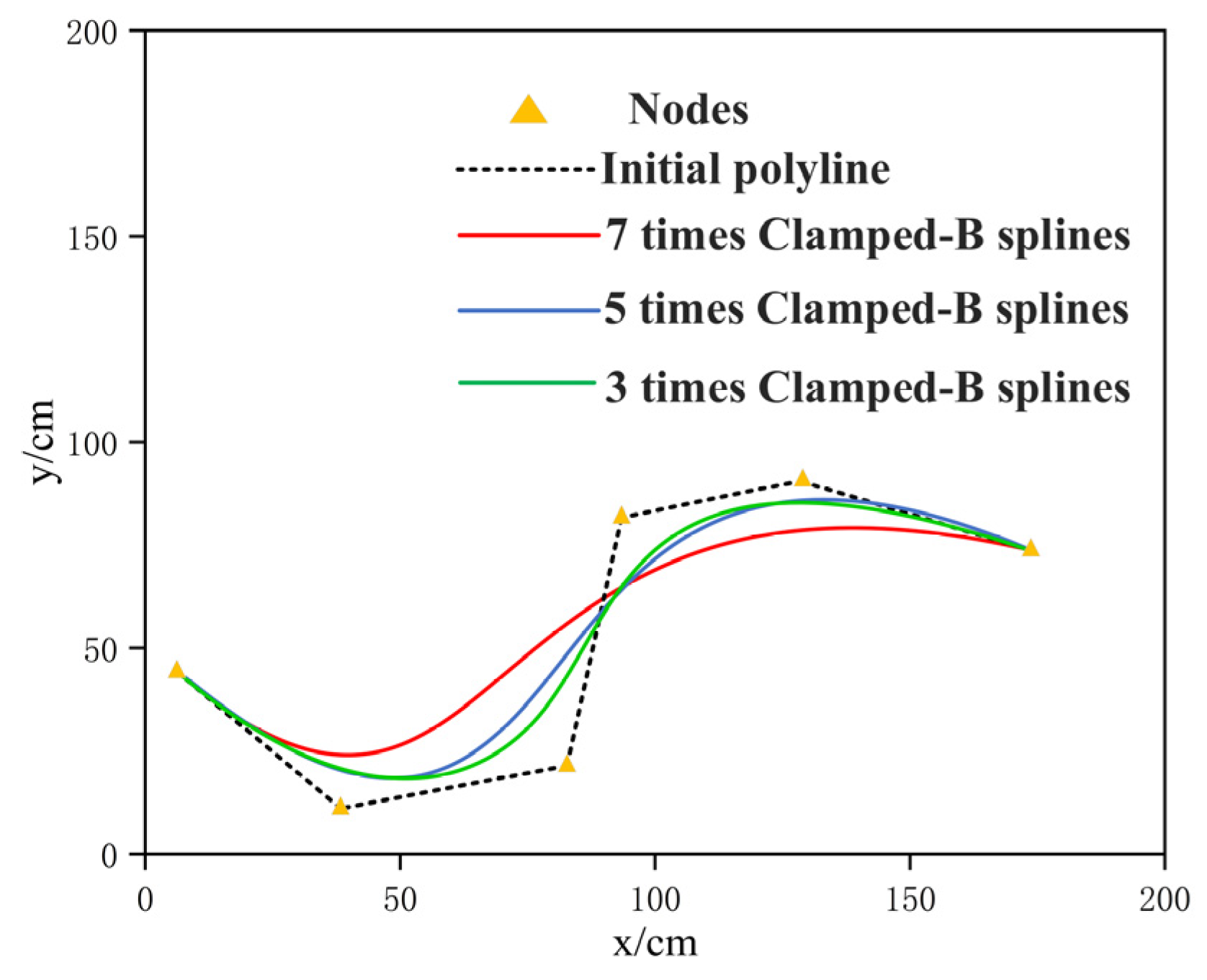
- The logarithmic function is introduced to improve the heuristic function coefficient. The adaptive adjustment of the A* algorithm is realized, and the key node selection strategy and 3 times Clamped-B spline are used to optimize and smooth the global path.
- (2)
- A DWA fuzzy controller based on the fuzzy control principle is proposed and designed, which adjusts the coefficient weight of the DWA evaluation function in real-time by judging the distance between the vehicle, obstacles, and target points.
- (3)
- A hybrid path planning method based on the improved A* algorithm and the fuzzy control DWA algorithm is proposed, and the global path key points are used as the local target points of the DWA to guide the vehicle and perform dynamic obstacle avoidance.
2. Related Work
3. Methods
3.1. Improved A* Algorithm
3.1.1. Optimization Heuristic Function
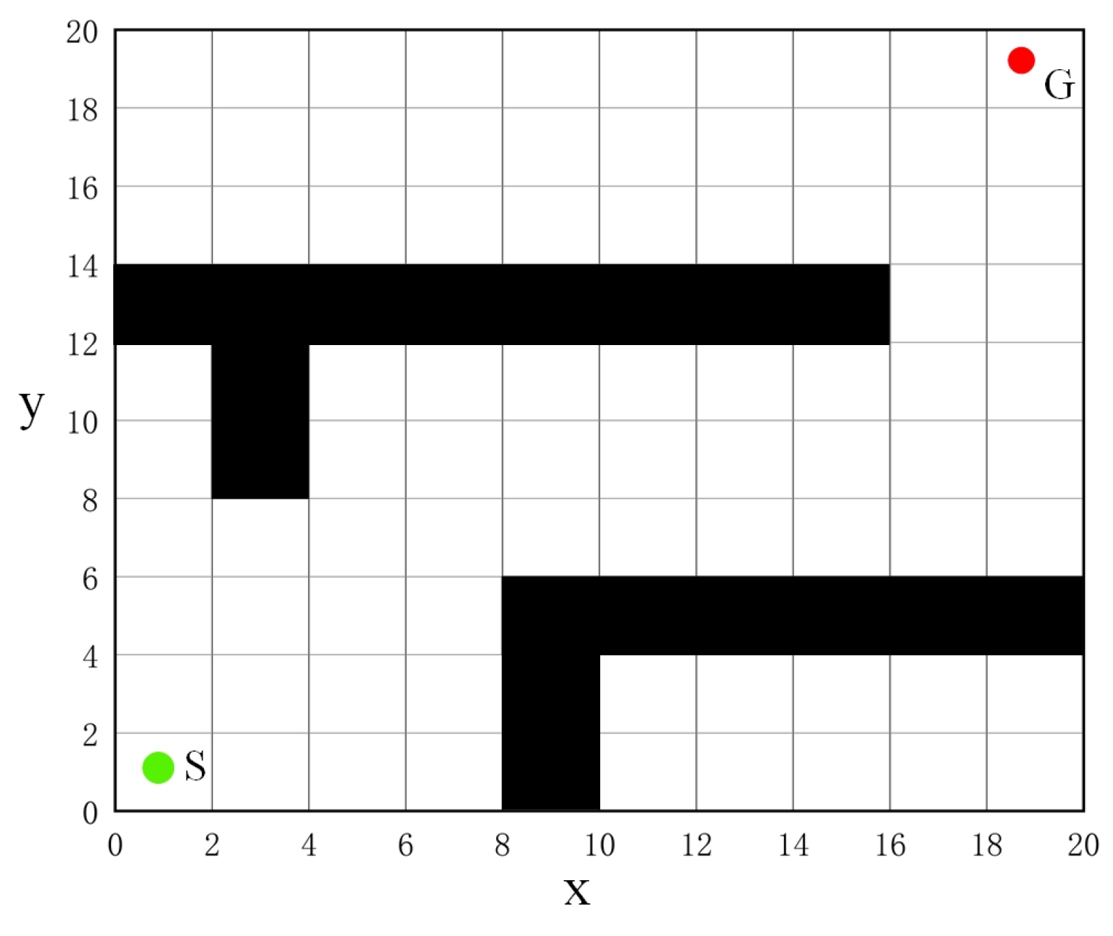
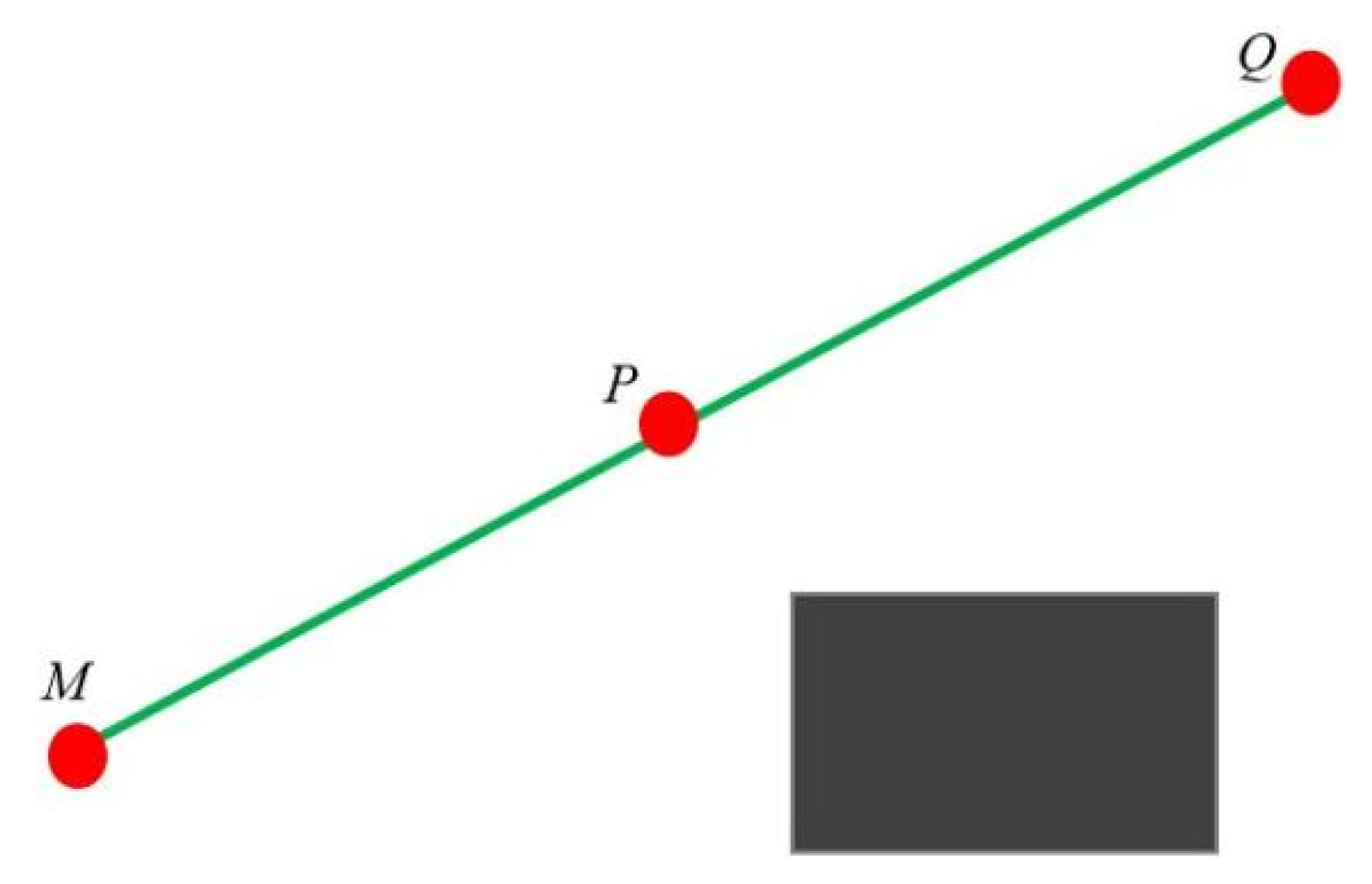
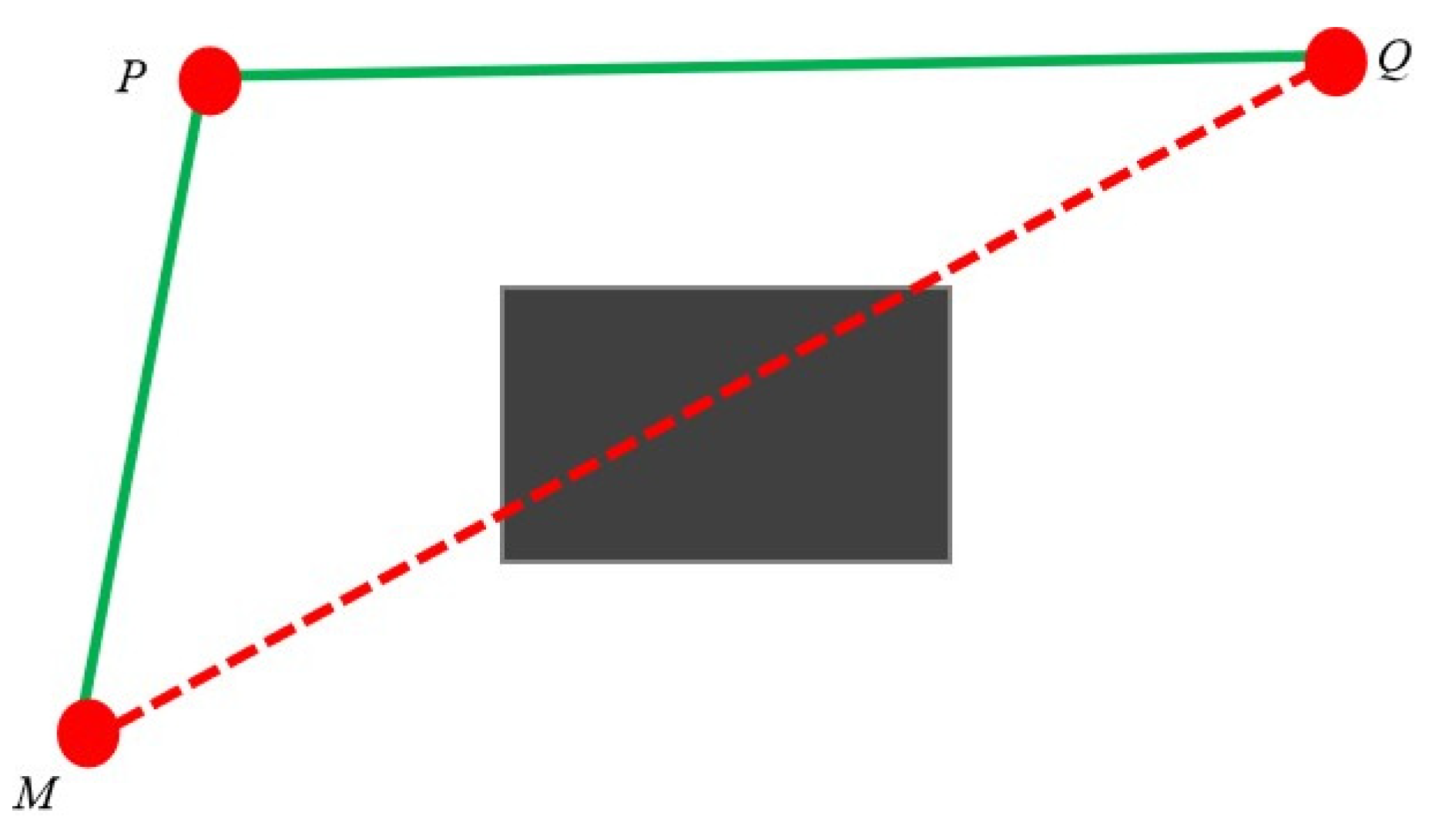
3.1.2. Key Node Selection Strategy
3.1.3. Path Smoothing
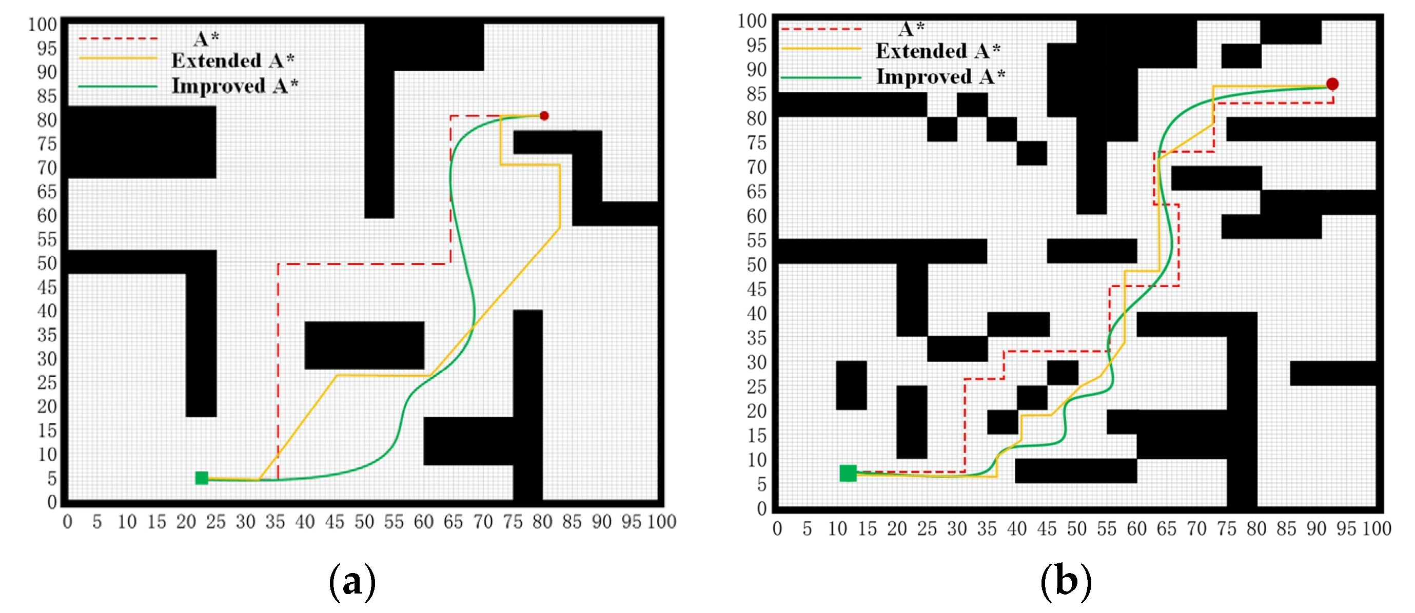
3.1.4. Simulation Experiment
3.2. Improved DWA Algorithm
3.2.1. DWA Algorithm
3.2.2. DWA Fuzzy Controller Design
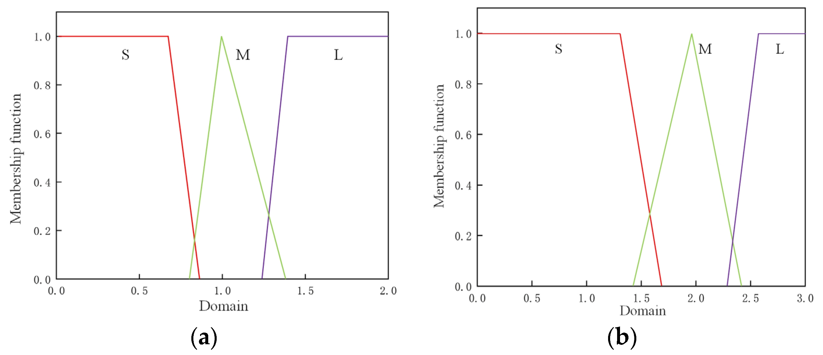
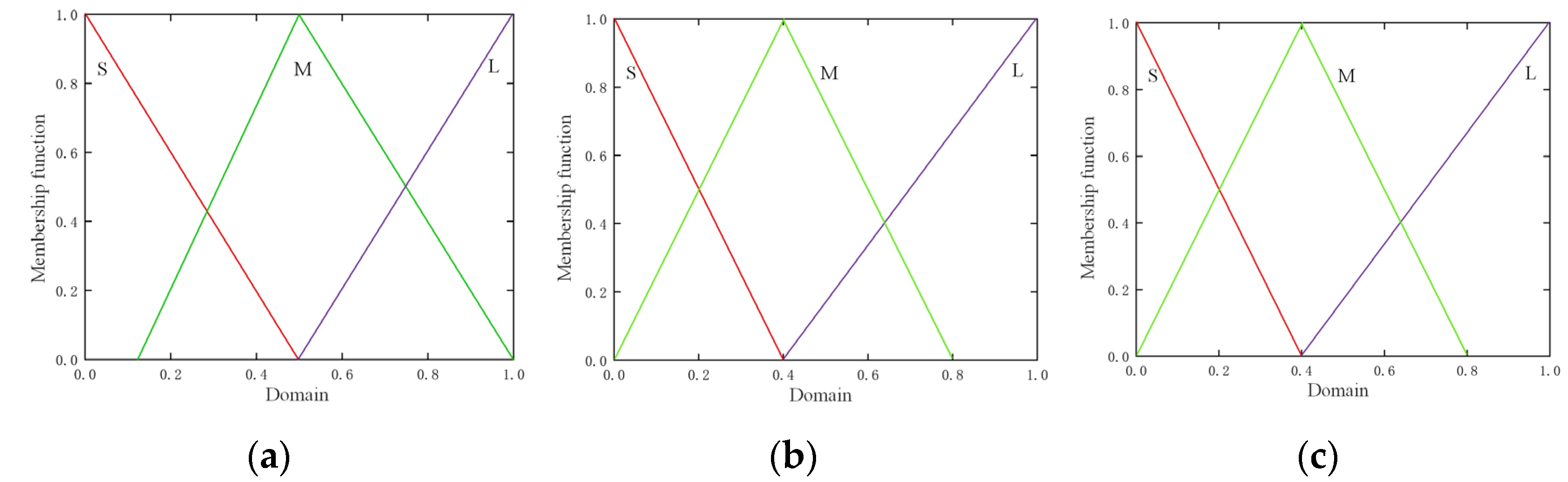
- Fuzzification
- Establish fuzzy rules.
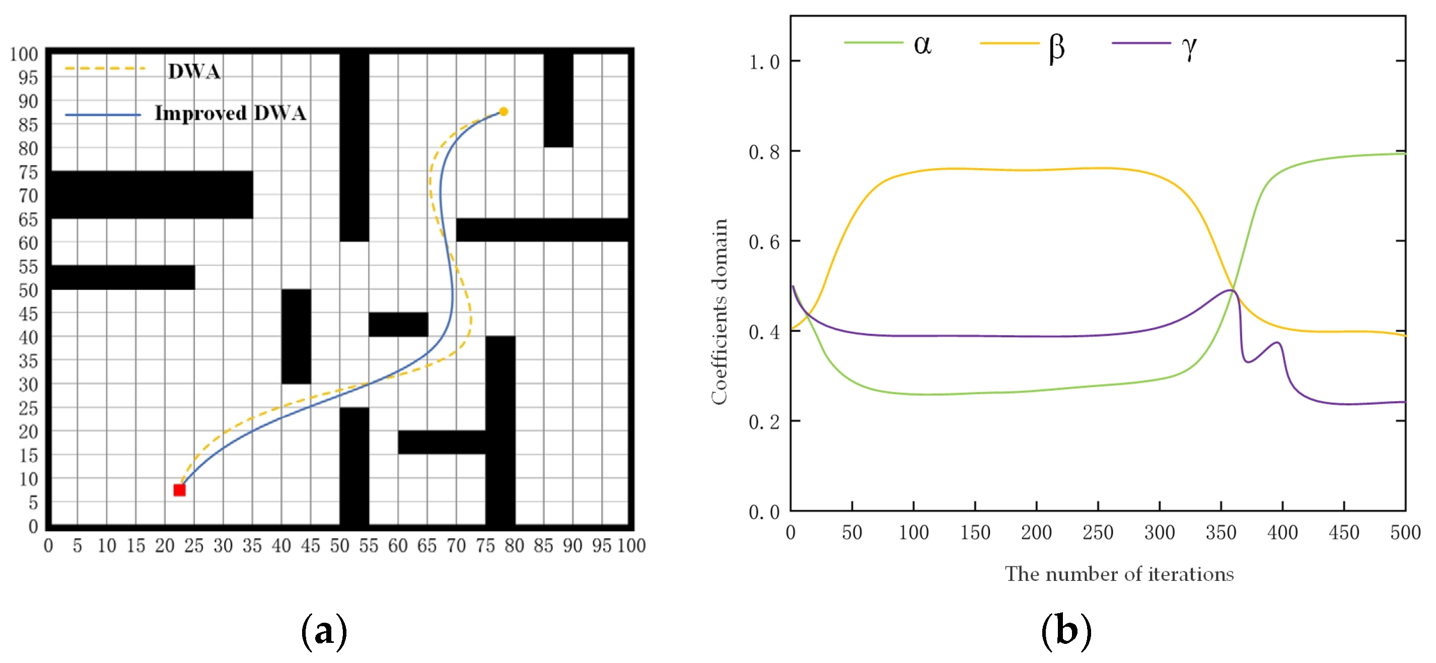
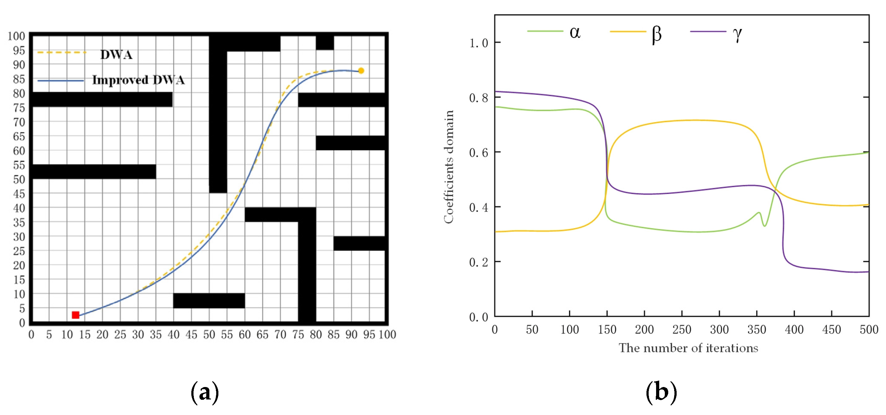
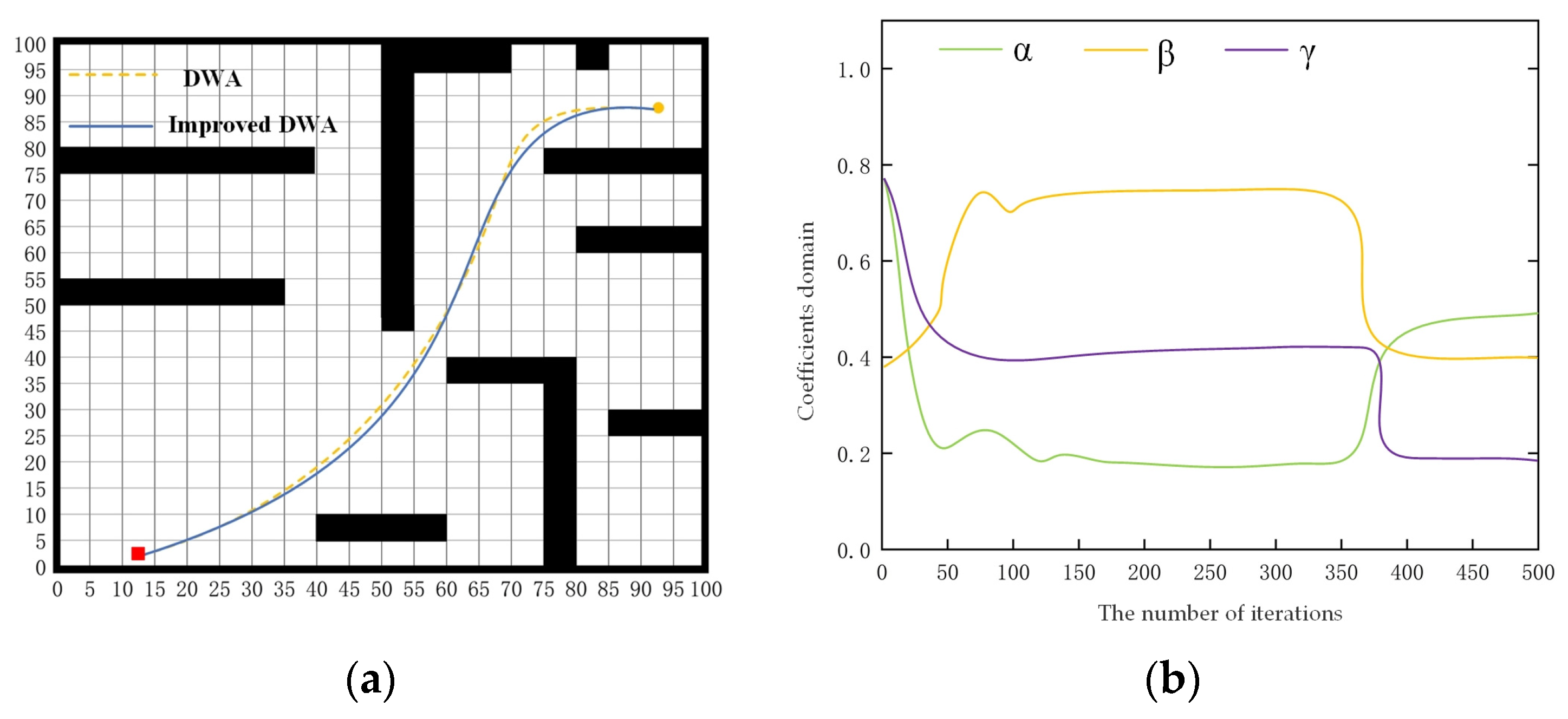
3.2.3. Simulation Experiment
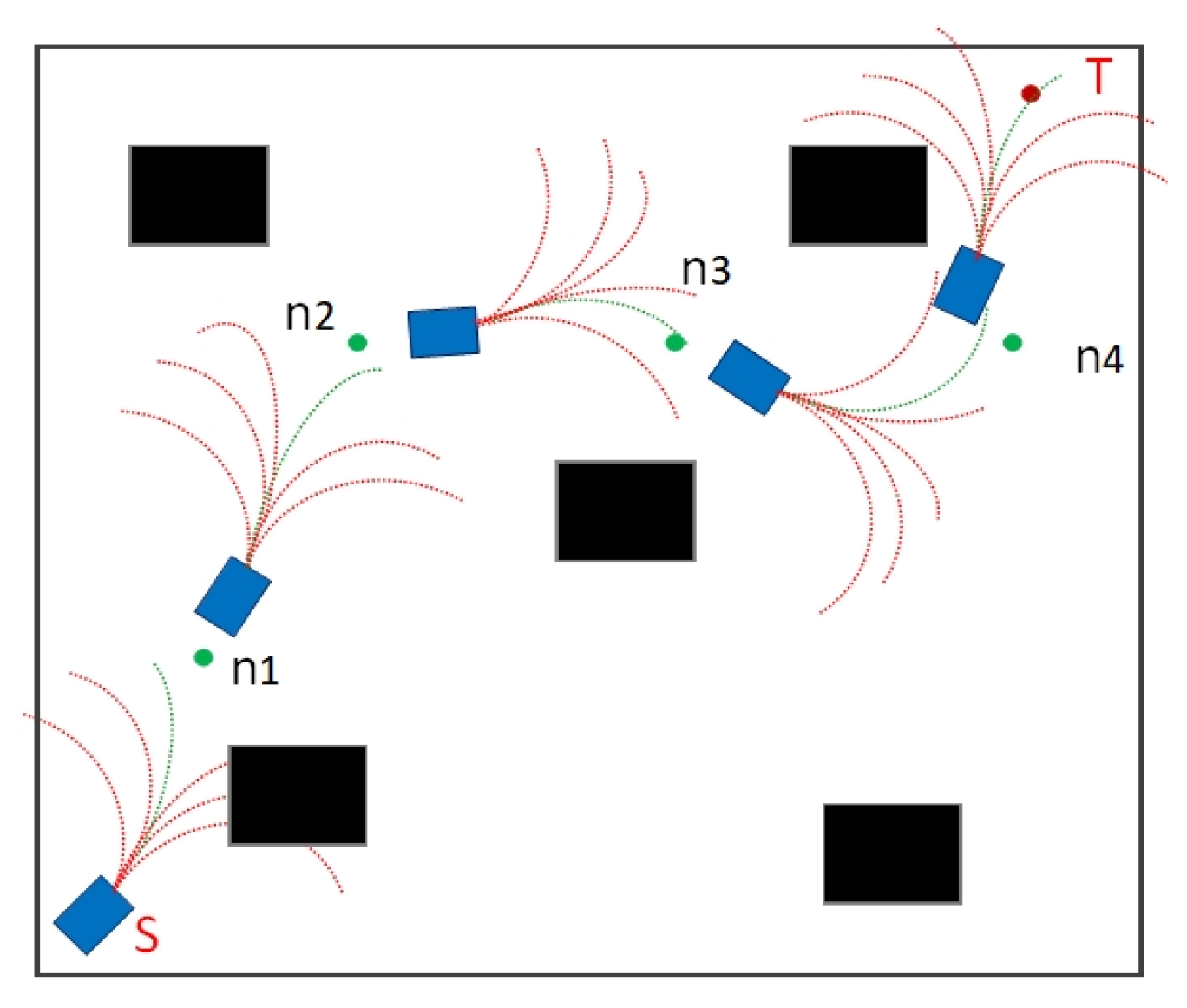
3.3. Fusion of Path Planning Method
4. Experiments
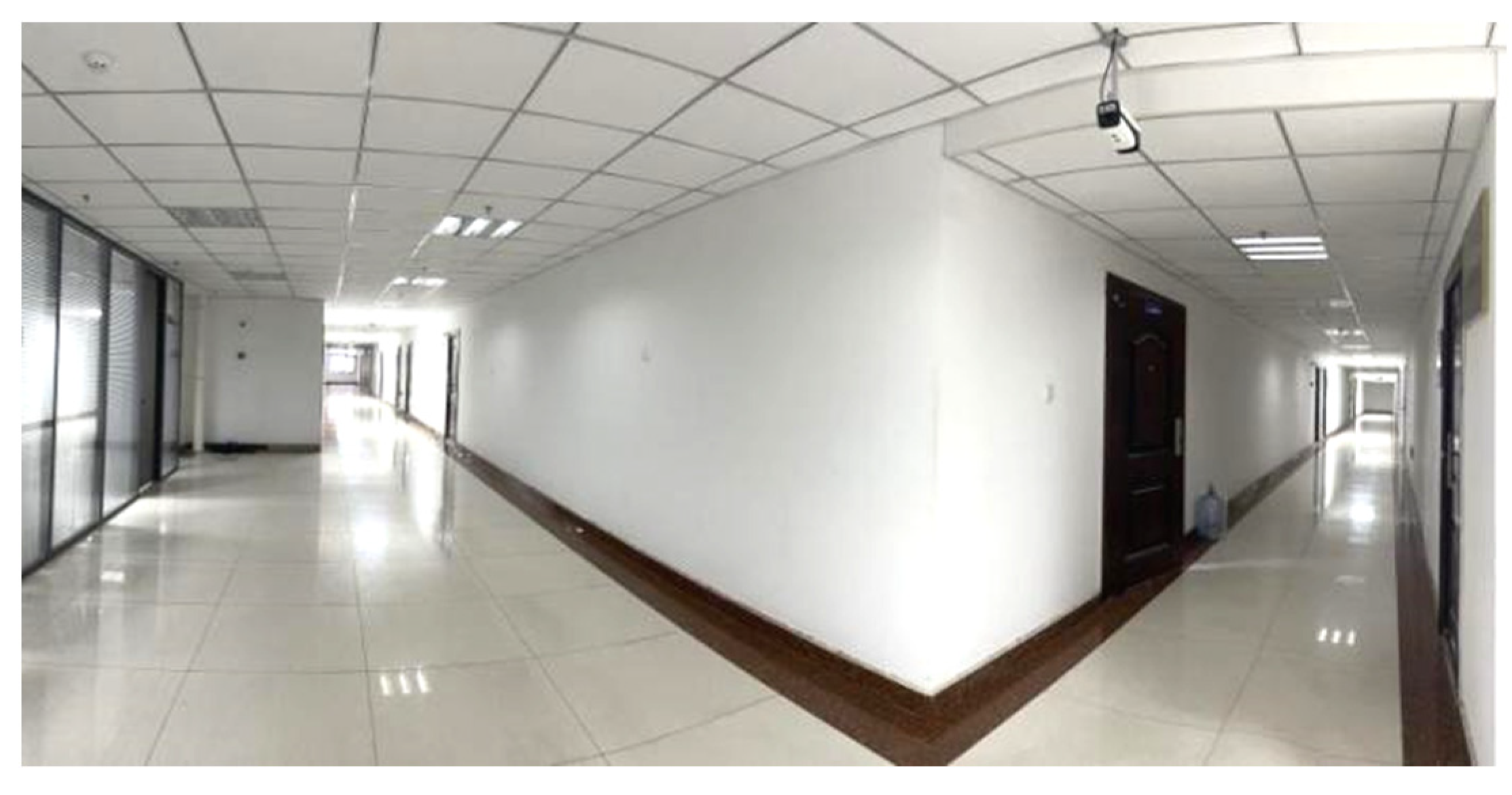
4.1. Experimental Settings
4.2. Analysis of Experimental Results
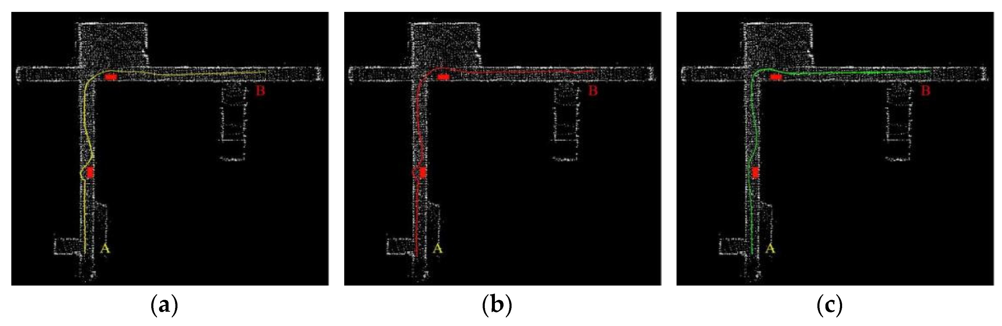
- Unknown environment
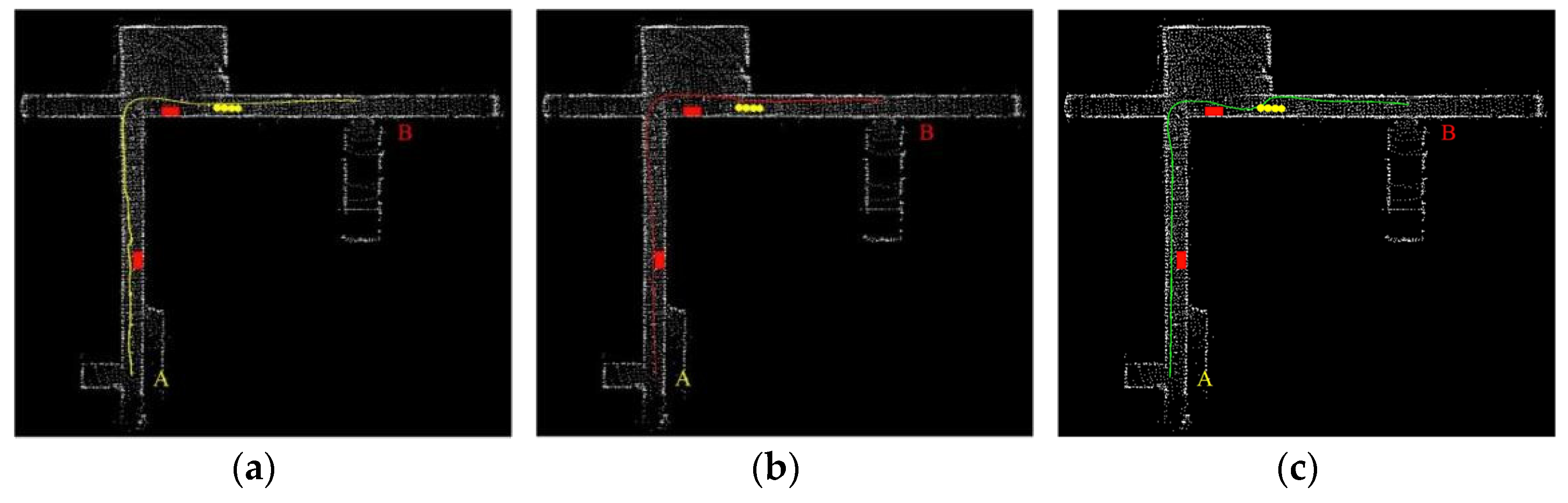
- Dynamic environment
5. Conclusions
Author Contributions
Funding
Institutional Review Board Statement
Informed Consent Statement
Data Availability Statement
Conflicts of Interest
References
- Hao, J.W.; Xiang, H.M. Obstacle avoidance path planning of mobile robot based on improved DWA. J. Phys. 2022, 2383, 012098. [Google Scholar]
- Jian, B.W.; Jiang, H.H.; Zhen, C.W. Modeling and verification of the operation process control of underground unmanned locomotives. J. Hefei Univ. Technol. 2018, 41, 773–779. [Google Scholar]
- Jin, Y. Feasibility study on unmanned driving of explosion-proof vehicles in coal mines based on 4G communication technology. Coal Mine Mach. 2016, 6, 186–188. [Google Scholar]
- Kai, C.; Zhi, G.L.; Xiao, M.Y. Research on unmanned driving system of trackless rubber-tyred vehicle in coal mine. J. Mine Autom. 2022, 6, 36–48. [Google Scholar]
- He, H.T.; Liao, Z.W.; Guo, W. Research and exploration of driverless technology of derackless rubber wheel car in coal mine. Coal Sci. Technol. 2022, 50, 212–217. [Google Scholar]
- Xiao, B.Z.; Xiang, Y. Trajectory Planning and Tracking Strategy Applied to an Unmanned Ground Vehicle in the Presence of Obstacles. IEEE Trans. Autom. Sci. Eng. 2021, 18, 1575–1589. [Google Scholar]
- Abdallaoui, S.; Aglzim, E.-H.; Chaibet, A.; Kribèche, A. Thorough Review Analysis of Safe Control of Autonomous Vehicles: Path Planning and Navigation Techniques. Energies 2022, 15, 1358. [Google Scholar] [CrossRef]
- Qin, H.; Shao, S.; Wang, T.; Yu, X.; Jiang, Y.; Cao, Z. Review of Autonomous Path Planning Algorithms for Mobile Robots. Drones 2023, 7, 211. [Google Scholar] [CrossRef]
- Yu, X.W. Reform and development of coal mine safety in China: An analysis from government supervision, technical equipment, and miner education. Resour. Policy 2022, 77. [Google Scholar]
- Thi Thao, M.; Cosmin, C. Heuristic approaches in robot path planning: A survey. Robot. Auton. Syst. 2016, 86, 13–28. [Google Scholar]
- Lun, Q.; Lun, X.H. Survey of UAV motion planning. IET Cyber-Syst. Robot. 2020, 2, 14–21. [Google Scholar]
- Lin, Z.; Wu, K.; Shen, R.; Yu, X.; Huang, S. An Efficient and Accurate A-star Algorithm for Autonomous Vehicle Path Planning. IEEE Trans. Veh. Technol. 2023, 3348140, 1–6. [Google Scholar] [CrossRef]
- Zhou, P.; Xie, Z.; Zhou, W.; Tan, Z. A Heuristic Integrated Scheduling Algorithm Based on Improved Dijkstra Algorithm. Electronics 2023, 12, 4189. [Google Scholar] [CrossRef]
- Wu, B.; Zhang, W.; Chi, X.; Jiang, D.; Yi, Y.; Lu, Y. A Novel AGV Path Planning Approach for Narrow Channels Based on the Bi-RRT Algorithm with a Failure Rate Threshold. Sensors 2023, 23, 7547. [Google Scholar] [CrossRef]
- Li, M.; Li, B.; Qi, Z.; Li, J.; Wu, J. Optimized APF-ACO Algorithm for Ship Collision Avoidance and Path Planning. Mar. Sci. Eng. 2023, 11, 1177. [Google Scholar] [CrossRef]
- Wang, Q.; Li, J.; Yang, L.; Yang, Z.; Li, P.; Xia, G. Distributed Multi-Mobile Robot Path Planning and Obstacle Avoidance Based on ACO–DWA in Unknown Complex Terrain. Electronics 2022, 11, 2144. [Google Scholar] [CrossRef]
- Pan, Y.; Yang, Y.; Li, W. A deep learning trained by genetic algorithm to improve the efficiency of path planning for data collection with multi-UAV. IEEE Access 2021, 9, 7994–8005. [Google Scholar] [CrossRef]
- Chen, R.; Hu, J.; Xu, W. An RRT-Dijkstra-Based Path Planning Strategy for Autonomous Vehicles. Appl. Sci. 2022, 12, 11982. [Google Scholar] [CrossRef]
- Li, X.; Tong, Y. Path Planning of a Mobile Robot Based on the Improved RRT Algorithm. Appl. Sci. 2024, 14, 25. [Google Scholar] [CrossRef]
- Zen, L.W. Improved A* algorithm and model predictive control- based path planning and tracking framework for hexapod robots. Ind. Robot 2023, 50, 135–144. [Google Scholar]
- Li, S.L.; Bin, W.; Hui, X. Research on Path-Planning Algorithm Integrating Optimization A-Star Algorithm and Artificial Potential Field Method. Electronics 2022, 11, 3660. [Google Scholar] [CrossRef]
- Algabri, R.; Choi M, T. Target recovery for robust deep learning-based person following in mobile robots: Online trajectory prediction. Appl. Sci. 2021, 11, 4165. [Google Scholar] [CrossRef]
- Tian, Y.L.; Rui, X.Y.; Guang, R.W.; Lei, S. Local Path Planning Algorithm for Blind-guiding Robot Based on Improved DWA Algorithm. Chin. Control. Decis. Conf. 2019, 31, 871–875. [Google Scholar]
- Hong, J.Z. Research on the path planning of coal mine scene inspection robot. Coal Mine Mach. 2022, 43, 45–47. [Google Scholar]
- Meng, J.L.; Xi, A.Z.; Zhan, G.W.; De, M.L. Research on the application of mine flood escape path based on bidirectional A* algorithm. Coal Eng. 2019, 51, 42–47. [Google Scholar]
- Jiu, S.B.; Mu, M.Z.; Shi, R.G. Based on the improved A * and artificial potential field algorithm Path planning. J. China Coal Soc. 2022, 47, 1347–1360. [Google Scholar]
- Zi, J.T.; Xue, H.G. Path planning of mine navigation device based on improved artificial potential field. J. China Coal Soc. 2016, 41, 589–597. [Google Scholar]
- Yuan, X.M.; Ming, R.H. Research on the key technology of mine-assisted transportation robot. Ind. Mine Autom. 2020, 46, 8–14. [Google Scholar]
- Noreen, I. Collision Free Smooth Path for Mobile Robots in Cluttered Environment Using an Economical Clamped Cubic B-Spline. Symmetry 2020, 12, 1567. [Google Scholar] [CrossRef]
- Zhen, Z.; Hua, L.Z. Real Time Path Planning of Robot by Combing Improved A∗ Algorithm and Dynamic Window Approach. Radio Eng. 2022, 52, 1984–1993. [Google Scholar]
- Lin, Z.; Yue, M.; Chen, G.; Sun, J. Path planning of mobile robot with PSO-based APF and fuzzy-based DWA subject to moving obstacles. Trans. Inst. Meas. Control. 2022, 44, 121–132. [Google Scholar] [CrossRef]


| Algorithm | Number of Nodes | Planning Time (ms) | Path Length | |
|---|---|---|---|---|
| Scenario 1 | A* | 172 | 213.915 | 159.682 |
| Extended A* | 166 | 193.178 | 154.424 | |
| Improved A* | 143 | 186.308 | 149.731 | |
| Scenario 2 | A* | 227 | 562.713 | 231.812 |
| Extended A* | 209 | 540.341 | 228.453 | |
| Improved A* | 189 | 494.104 | 217.036 |
| Rule Number | Input | Output | |||
|---|---|---|---|---|---|
| G | O | α | β | γ | |
| 1 | S | S | M | M | S |
| 2 | S | M | L | M | S |
| 3 | S | L | L | S | S |
| 4 | M | S | M | M | S |
| 5 | M | M | M | M | M |
| 6 | M | L | M | S | M |
| 7 | L | S | S | L | M |
| 8 | L | M | S | L | M |
| 9 | L | L | L | M | L |
| Parameter | Value | Parameter | Value |
|---|---|---|---|
| α | 0.15 | Maximum angular rate | 60 rad/s |
| β | 0.4 | Maximum linear acceleration | 0.1 m/s2 |
| γ | 0.3 | Trajectory prediction time | 2 s |
| Maximum linear speed | 1 m/s |
| Experiment | Algorithm | Planning Time (s) | Path Length | Success Rate |
|---|---|---|---|---|
| Scenario 1 | DWA | 235.172 | 196.342 | 90% |
| improved DWA | 246.374 | 184.751 | 96% | |
| Scenario 2 | DWA | 219.532 | 174.285 | 94% |
| improved DWA | 224.784 | 170.764 | 98% | |
| Scenario 3 | DWA | 220.429 | 175.479 | 86% |
| improved DWA | 226.425 | 169.427 | 96% |
| Name | Parameters |
|---|---|
| Shape | 2490 × 1550 × 616 mm |
| Bearing spacing | 1900 mm |
| Wheel spacing | 1355 mm |
| Maximum speed | 40 km/h |
| Steering type | Four-wheel steering |
| Braking type | Four-wheel disc brake |
| Equipment | Model |
|---|---|
| Computer | CPU i7-9700 |
| Graphics card | |
| RTX3060 | |
| LIDAR | Velodyne VLP-16 |
| IMU | LPMS-IG1 |
Disclaimer/Publisher’s Note: The statements, opinions and data contained in all publications are solely those of the individual author(s) and contributor(s) and not of MDPI and/or the editor(s). MDPI and/or the editor(s) disclaim responsibility for any injury to people or property resulting from any ideas, methods, instructions or products referred to in the content. |
© 2024 by the authors. Licensee MDPI, Basel, Switzerland. This article is an open access article distributed under the terms and conditions of the Creative Commons Attribution (CC BY) license (https://creativecommons.org/licenses/by/4.0/).
Share and Cite
Zhang, C.; Yang, X.; Zhou, R.; Guo, Z. A Path Planning Method Based on Improved A* and Fuzzy Control DWA of Underground Mine Vehicles. Appl. Sci. 2024, 14, 3103. https://doi.org/10.3390/app14073103
Zhang C, Yang X, Zhou R, Guo Z. A Path Planning Method Based on Improved A* and Fuzzy Control DWA of Underground Mine Vehicles. Applied Sciences. 2024; 14(7):3103. https://doi.org/10.3390/app14073103
Chicago/Turabian StyleZhang, Chuanwei, Xinyue Yang, Rui Zhou, and Zhongyu Guo. 2024. "A Path Planning Method Based on Improved A* and Fuzzy Control DWA of Underground Mine Vehicles" Applied Sciences 14, no. 7: 3103. https://doi.org/10.3390/app14073103
APA StyleZhang, C., Yang, X., Zhou, R., & Guo, Z. (2024). A Path Planning Method Based on Improved A* and Fuzzy Control DWA of Underground Mine Vehicles. Applied Sciences, 14(7), 3103. https://doi.org/10.3390/app14073103