1. Introduction
Offering complex products for highly developed markets poses the challenge of tailoring them to the individual requirements of the customer. Centerpieces in efficiently realizing this are a suitable product model that contains degrees of freedom representing adjustable product properties and options and an information system that is capable of translating customer inputs into a valid product specification [
1,
2,
3].
Today’s computational design systems offer plenty of possibilities to combine the two. In addition to approaches such as algorithmic and generative design, the traditional parameter and chronology-based computer-aided design (CAD) systems that are still very common in mechanical and plant engineering implement different techniques to model solution spaces instead of a single product variant [
4,
5,
6]. A sophisticated approach is knowledge-based CAD configuration. CAD-based configuration systems usually offer additional functionality that is associated with the complete set of geometrical data and justify the implementation effort. Such systems contribute to complexity management, e.g., by automatically checking for manufacturability, reducing the configuration task through the automation of part or sub-assembly design and optimization, and generating assembly instructions or other documentation [
7,
8,
9].
Independently from the implementation, user inputs commonly are variables and the selection of options [
10,
11]. For complex products like in plant engineering, where the configuration is altered many times during the specification process, identifying and changing the respecting parameters requires high attention and a level of abstraction. From the perspective of user experience design, lowering such interaction costs, i.e., the cognitive and physical load to reach the goal of interaction, is a design rationale [
12,
13]. For example, virtual and augmented reality applications reach this goal by graphical and interactive control elements that are attached to the real geometry and allow for immediate feedback [
14,
15].
Implementing such control elements in a CAD model poses additional constraints for model creation. There are three reasons for that: First, since the rebuild time of the CAD model is crucial, an efficient model setup and advanced parameter planning with streamlined dependencies between the geometrical elements is a necessity, avoiding loops between part and assembly rebuild. Second, after interaction with the control element, its drop position usually needs to be checked regarding valid limits and possibly translated to a given increment, which results in additional restrictions and a feedback loop. Third, the interaction between the geometric model and the knowledge base of the configuration system requires a reasonable algorithmic abstraction for the functions to be achieved and, if necessary, additional parameters for, e.g., calculation and plausibility checks [
16,
17].
From a methodology point of view, many contributing aspects of creating such interactive control elements are covered by literature, e.g., defining levels of detail, working with skeletons, and applying advanced or external knowledge-based control of CAD model parameters [
18,
19,
20]. The crucial point is their combination and implementation in a given CAD system. Thus, this article addresses the research question:
How to implement interactive geometric control elements in a CAD assembly, and which generalized design features are necessary, independently from the CAD system?To answer the question, the authors follow a learning-by-building approach based on Hevner’s design science research cycles [
21]. The knowledge base is presented in the following
Section 2, where foundational aspects of parametric and knowledge-based modeling in CAD systems and model planning methods are briefly introduced.
Section 3 then introduces the case study, which is an interactive modular piping 3D CAD configuration system. Afterward,
Section 4 reflects the additions to the knowledge base in the form of generalized design features. The article closes with a summary and conclusion in
Section 5.
2. Background
2.1. Knowledge-Based Engineering and Knowledge-Based CAD
The concept of knowledge-based engineering (KBE) involves a shift in computer-aided product modeling from documenting a single product variant to modeling solution spaces where a variant can be found to meet a set of requirements [
6,
7]. Two fundamental questions must be answered when building a KBE system: how to model the solution space, and how to explore it to achieve a design task [
5,
22].
In algorithmic modeling, the focus is on automating the design process rather than pre-formulated solutions [
4,
23]. Algorithms are used to extract product properties from requirements and build product design rules, also taking into account external data or numerical simulations [
24,
25,
26]. Therefore, a parametric product master model is unnecessary, as this approach aims to generate an individual product for each set of customer requirements. This is particularly favorable for complex geometries and pure configuration designs but largely restricts subsequent parametric editing of the variant. Instead, requirements and design rules need to be altered to create the updated version [
27,
28,
29].
When using parametric design, editing a product model is made easier, allowing for geometry re-use and also embedding design intent with geometry [
18,
30]. Defining logical and mathematical relations between parameters helps differentiate leading and driven parameters. The designer models geometry and plans configuration concepts and parameterization of the component [
7,
31,
32]. Today’s CAD system can create user-defined parameters not only for length or angular dimensions but also to support the computation and handling of other units such as for stresses, forces, or moments of inertia. This feature allows for the direct integration of comprehensive dimensioning formulas into the CAD model, making it more efficient and convenient for users to work with [
33]. Furthermore, some CAD systems offer the option to specify design rules. These rules usually take the form of if–then–else statements, which link, e.g., the suppression of specific features to geometric or other parameters [
34,
35].
As components become more complex, the need for a well-structured configuration with parameters at various levels becomes increasingly imperative. Assemblies may contain a skeleton model that defines the positioning of components and their geometrical characteristics based on a structural design. The skeleton itself can have different features and relations to its child models, e.g., the skeletal geometry can be used as a reference model or its geometric parameters can be linked to the child models via equations or by design rules [
18,
19].
The control of parameters can also be externalized. Most CAD systems allow for linking or embedding spreadsheets, providing additional mathematical and statistical capabilities compared to the CAD system alone. Lookup tables can be integrated for selecting standard parts based on geometric or load information. With this, basic reasoning functions are available [
33,
36]. Other ways of integrating reasoning are the use of script languages and macros within the CAD system and coupling external knowledge-based systems for parameter determination [
18,
33].
2.2. Model Planning for Knowledge-Based CAD
When creating knowledge-based CAD models, it is important to focus on the control and rebuild concept of the model itself, as it consists of multiple geometric features and domain knowledge artifacts that are strongly intertwined. Parameters that are constrained, correlated, or referenced create dependency chains that must remain flat. Parameter trees, parameter plans, and constraint networks are used as planning aids to define and manage the dependencies between parameters [
37,
38,
39].
The literature discusses also the application of KBE system development methodologies for planning knowledge-based CAD models. [
40,
41,
42]. Two methods have gained widespread use: MOKA [
43] and CommonKADS [
44,
45]. While the former emphasizes knowledge engineering and informal modeling, the latter focuses on formal modeling. The CommonKADS models are specifications for configuration-based systems and are divided into three categories: context includes the models of organization, task, and agents, which together answer questions about the need and benefits of developing a KBE system. The concept level includes two important models: the knowledge model and the communication model. These models define the type of KBE system required and how its internal elements are related to each other. The design model connects the previous models and leads to the final design at the artifact level so that it can be implemented in a given environment [
45,
46].
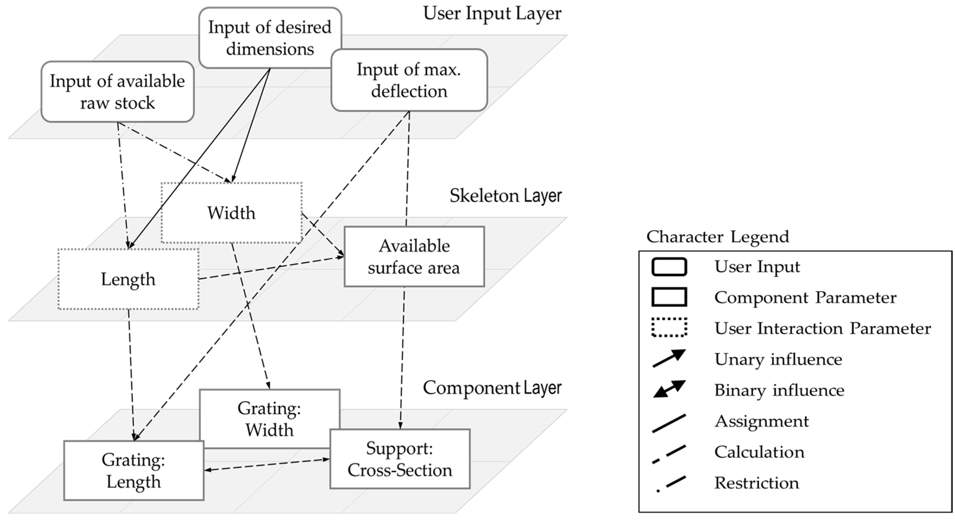
An extension of the CommonKADS approach is the correlation model (
Figure 1), which was developed specifically for planning the parametrization of CAD models [
16]. This tool supports designers to model correlations only top–down, avoid circular references, and distinguish between different hierarchy levels. Additionally, it visualizes the length of a dependency chain to estimate model efficiency. The correlation model is divided into three layers. The user input layer consists of all the parameters that the user communicates to the system. The model is visualized with the parameter control of a steel platform: the user enters the desired dimensions, maximum deflection, and the available raw stock. These inputs restrict the size of the beams for the support or the gratings. The skeleton layer is the abstraction of the parameter control concept and transforms the user inputs to the control parameters of the single components. The parameters on this layer can be used to define a design skeleton or derive interaction elements such as drag points. The component layer connects elements of the knowledge-based CAD model, such as geometric features in a part model or components in an assembly model, to the other layers.
3. Learning by Building: Interactive Modular Piping 3D CAD Configuration System
The design of 3D piping to connect installations and instrumentation is an activity in many engineering disciplines, such as plant engineering, ship design but also mechanical engineering, and infrastructure planning [
47,
48,
49,
50]. Engineering systems support designers in finding intersections between pipe routings, generating isometrics, and creating bills of materials.
Nonetheless, routing is mainly performed manually following a pearl chain principle from the start to end connector. Completely automatic pipe routing is challenging. Although the task can be abstracted into a set of classical algorithmic problems, the resulting computational complexity of real-world applications currently restricts intelligent routing applications to a comparatively simple set of template routings for single already-capacitated routes [
51,
52].
3.1. System Specification and Limitations
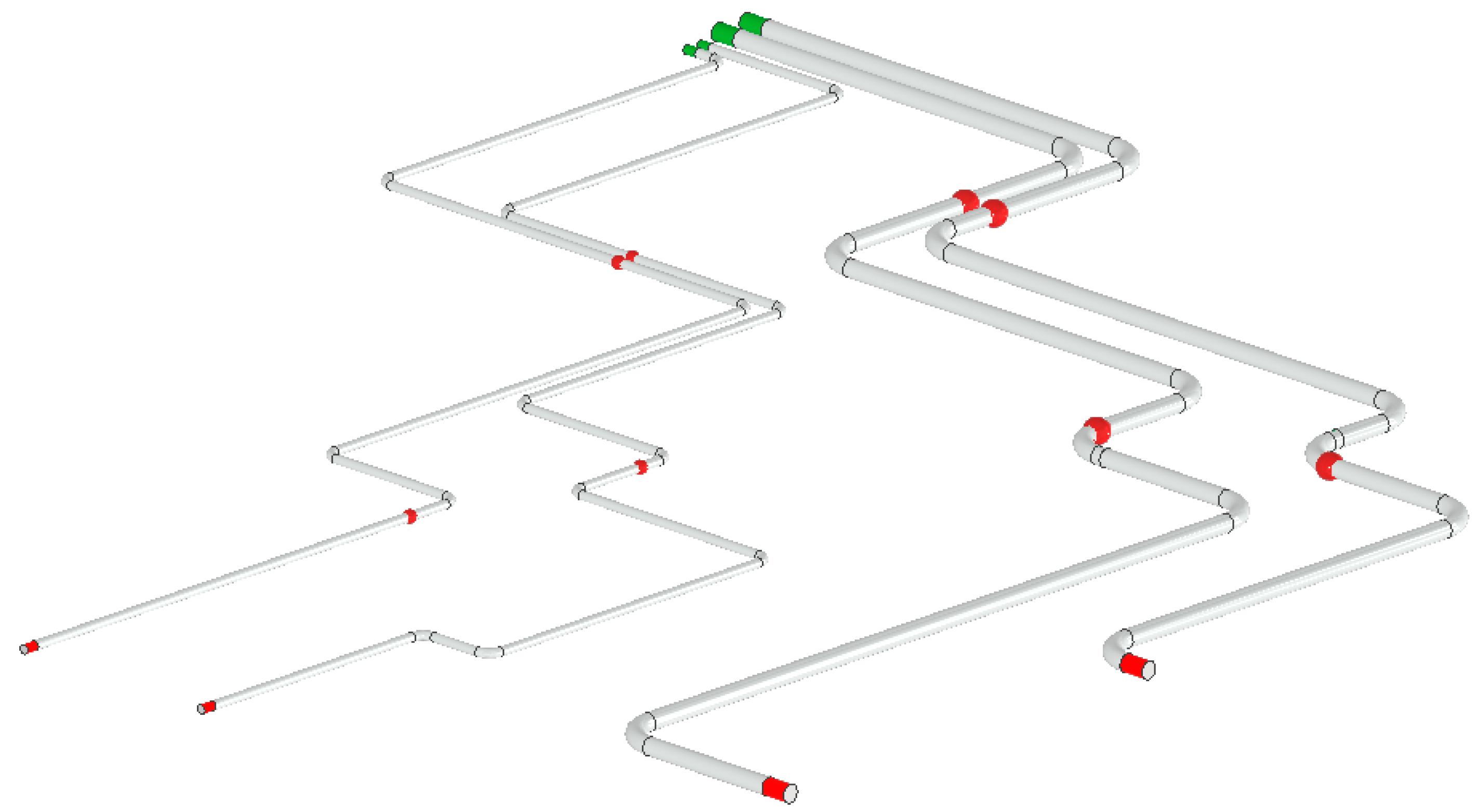
The basic idea behind the industry use case of this study is not complete automation for routing designs, as shown in
Figure 2, but to raise the efficiency in the design process with an interactive modular piping 3D CAD configuration system. Designers should have the ability to specify the position and orientation of the starting and ending connectors (represented by green and red cylinders, respectively), as well as define and subsequently modify the position and orientation of instrumentation or supports (represented by red spheres), and efficiently add routings between them.
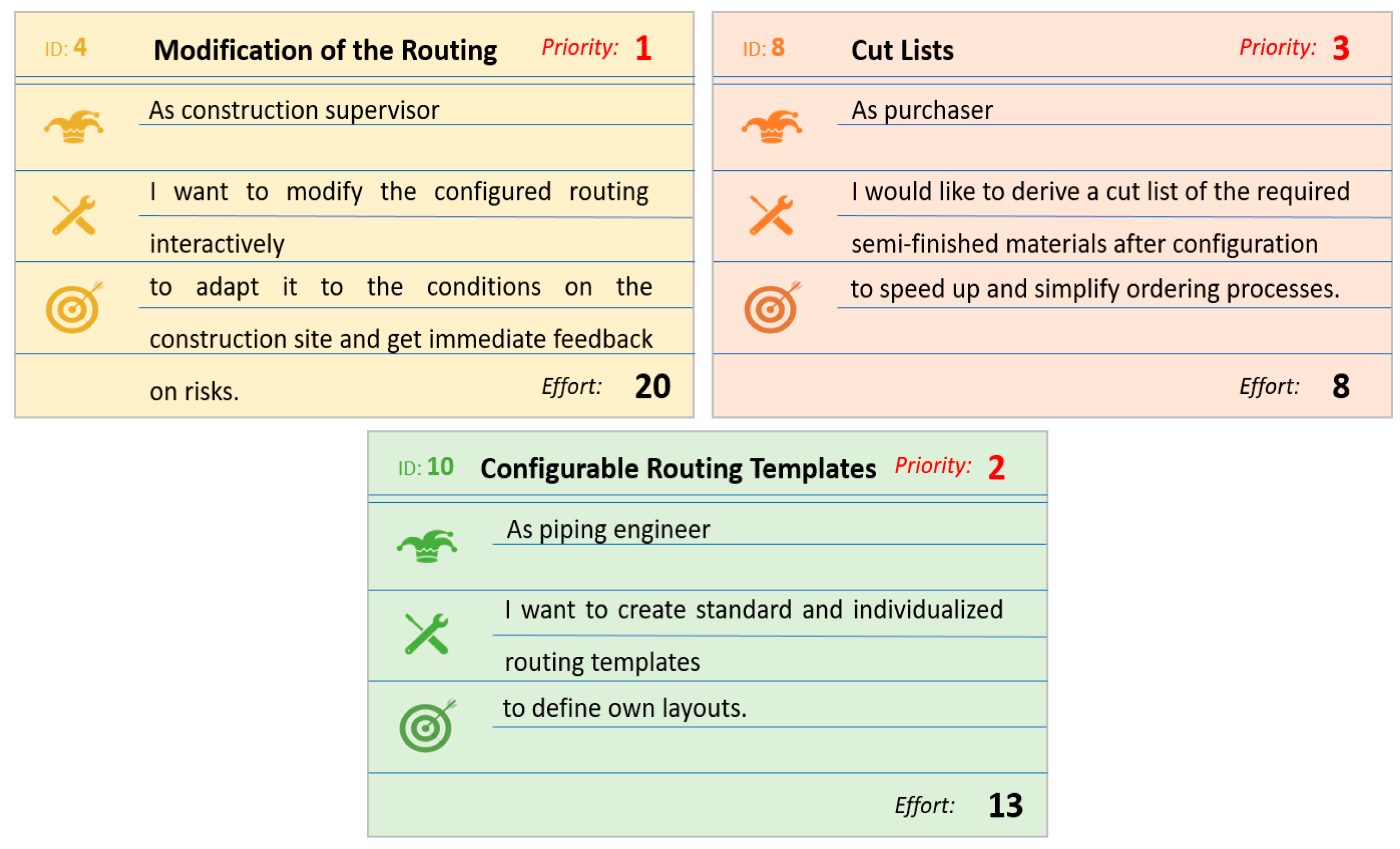
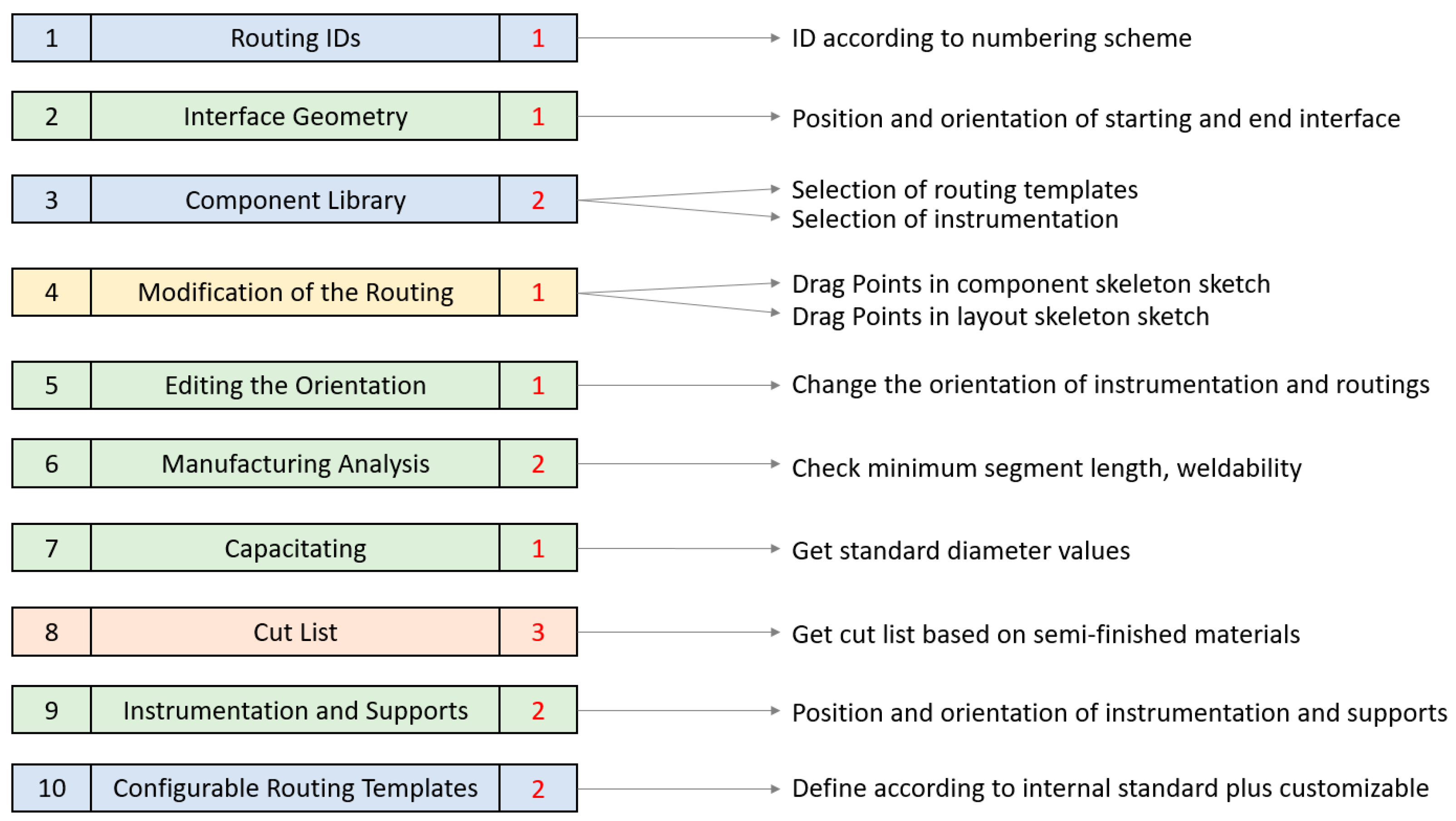
To specify the configuration system, a user group consisting of piping engineers, construction supervisors, a purchaser, and project managers was interviewed and invited to create user stories based on their experience and obstacles they observed in past projects (
Figure 3). Before creating a feature list, the development team prioritized tasks, estimated effort, and then mapped user stories to features. (
Figure 4). To simplify the implementation process, a modular architecture was chosen.
In addition to the basic layout (user stories 1, 2, 3, 5, 7, 9, and 10), user story 4 from the construction supervisor is particularly relevant for this case. When planning meets the construction site, many routing modifications may occur due to terrain differences, support foundation positioning or obstacles. When the construction supervisor has access to the design data but is not the originator of the 3D CAD model, they usually just comment on the design and send it back to engineering. For such modifications, the feedback of the engineering department is necessary in many cases as restrictions need to be checked, e.g., pressure drop, necessary slope, and manufacturability.
A basic requirement was stated that modifications of the routing should be handled directly to avoid errors and save time by using the configuration system. In this case study, the modification of a routing should trigger two actions. First, after the update, the routing assembly is checked for basic manufacturability restrictions, such as minimum segment lengths and weldability. Secondly, the cut list should be updated and compared to the initial one to ensure that the same amount of semi-finished materials is kept.
The configuration system is implemented directly into the CAD environment of Autodesk Inventor using its base functionalities. The initial release of the configuration system is defined as a technology demonstrator to show basic workflows and functionalities, and the following limitations are applicable:
Branches: If the routing contains branches, these are treated as instrumentation without flanges. The pipe tee is positioned and aligned directly on a drag point.
Reducers: Reducers are handled in the same way as instrumentation and aligned on a drag point.
Compensators: The check for length compensation due to thermal expansion is neglected and placing compensators is subject to subsequent manual refinement.
Slope: The slope check is neglected. This could be included in the system either directly in the path sketches of the routing templates or in the parametrics of the layout.
Intersection warning: Instead of a separate intersection analysis, the existing assembly interference analysis of the CAD system is used manually.
Based on the concept of reducing interaction costs, the user group and developers refined the interaction functionality to be implemented as drag points.
3.2. Program Flow and Implementation Concept
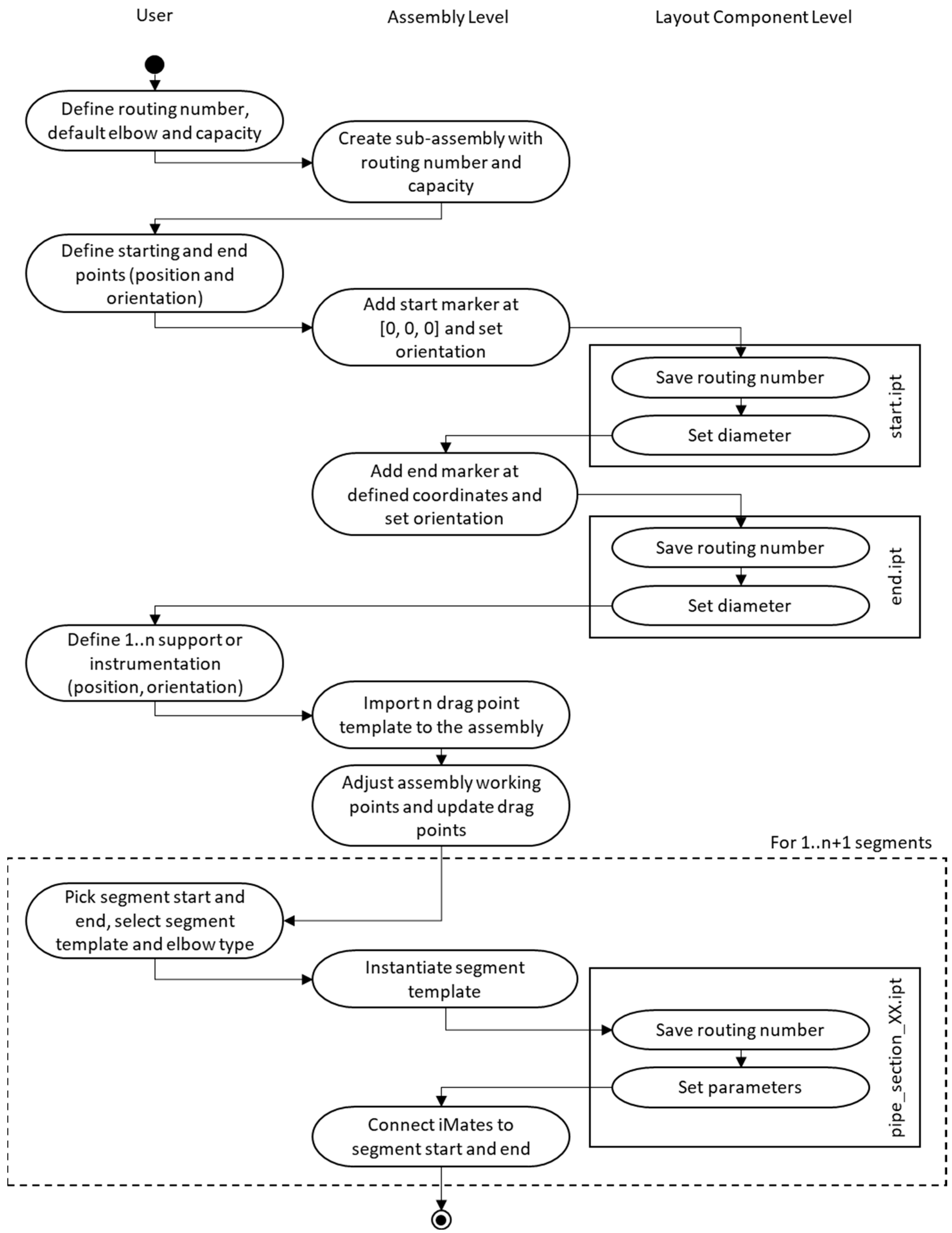
After the context was clarified, the development team continued to follow the extended CommonKADS approach and started to define the models at the concept level. In addition to gathering all relevant data from industry standards and manufacturing expertise in the form of rules and general equations, the developers collaborated with piping engineers to define a workflow for configuring the pipe routings (
Figure 5).
Typically, when adding routings to pre-existing infrastructure and instrumentation that already have calculated capacity, the first step is to define the routing number, the default elbow radius, and the input capacity. The draft diameter is then calculated based on these inputs and chosen according to the project-relevant standards. The configurator then creates a sub-assembly for the piping with the corresponding metadata in the background. This assembly later contains two levels of detail: one with a simplified sweep geometry and one with the actual piping assembly.
The next step is to define the start and end connectors of the routing both with position and orientation. Therefore, either existing connectors can be selected or the connectors are virtually declared. The configuration system then instantiates the corresponding markers on a layout component level. The drag points are defined in the same way. To simplify the later assembly process and geometric constraining, the configuration system additionally should add work points to each drag-ball position.
Afterward, when the routing is formally declared, the engineers can start adding predefined segment templates. To do so, the engineer picks the starting and target reference for the new segment. In the background, the configurator instantiates the geometry to the routing assembly, assigns all necessary parameters, and adds geometry constraints to the model. To replace a routing template, the old one is deleted and a new one is inserted the same way. For the majority of routings, three drag points per route are sufficient.
3.3. Implementation in Autodesk Inventor Professional
The technology demonstrator was implemented using basic functionalities in the CAD system Autodesk Inventor Professional. CAD administration requested that the system be maintained in-house by expert applicants without requiring deep programming knowledge. The development team decided to use mainly the iLogic scripting environment. iLogic is a basic language directly integrated with Inventor and is easy to understand. To simplify automation programming, users can utilize a comprehensive structure and a snippet library. iLogic rules are no rules in the traditional sense but routines and functions that can be nested and combined with user inputs. In comparison, its functionality is smaller than with the application programming interface but, if necessary, VBA macros can be executed by iLogic rules as well.
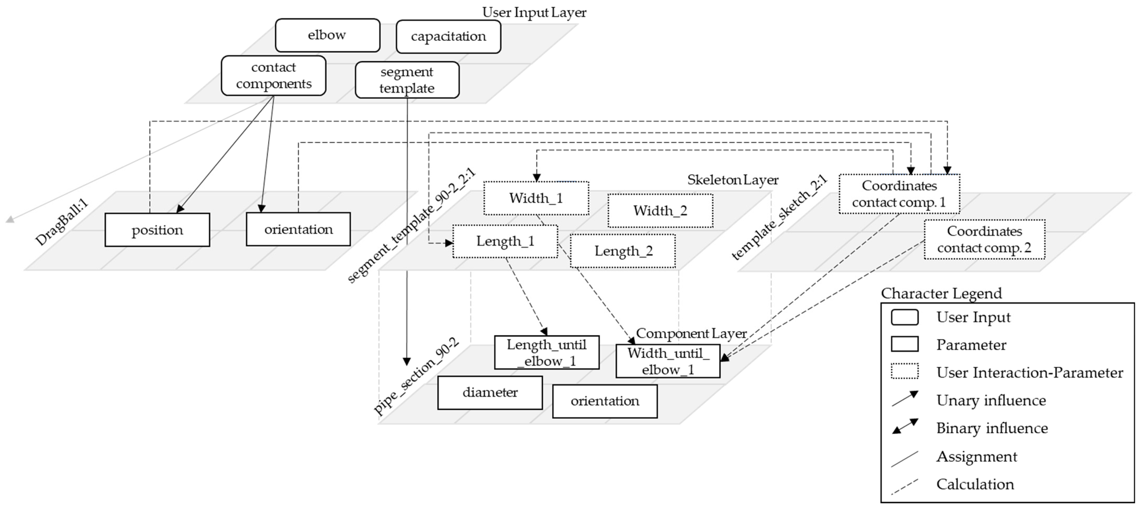
Having this in mind, the development team worked out a correlation model instantiating three layers (
Figure 6). The skeleton layer consists of a routing skeleton (template sketch) and the references for the single segment templates. These need to be constrained mathematically. Later, when a drag point is freely moved, its coordinates are determined, rounded to a given increment, and handed over to the segment templates and the parts on the component level. To raise the efficiency, some parameters are directly handed over from the user input layer to the component layer. Since iLogic does not allow for creating new variables at runtime, single routing templates with one, two, and three drag points are created so that all predetermined parameters can be constrained beforehand.
3.3.1. Segment Templates
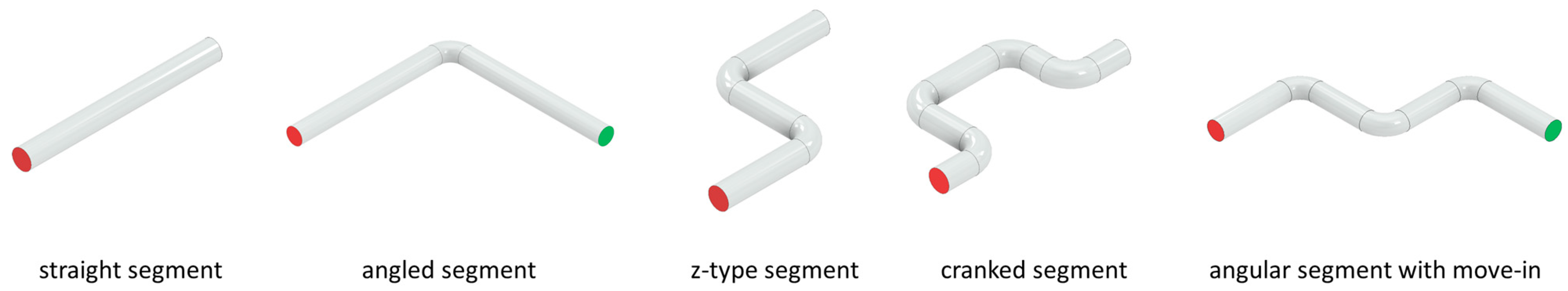
The specification of the piping engineers included five basic segment templates (
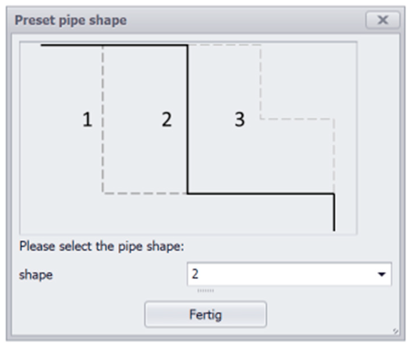
Figure 7). The first is a straight segment where the distance between two drag points is bridged. For the high level of detail, the assembly contains a sequence of standard-length pipes, joint preparation, and welding information. The second is an angled segment with one elbow to connect instrumentation perpendicularly, while the z-type bridges instrumentation with parallel axis with an offset. The fourth and fifth are a cranked and angular segment to run around obstacles.
In general, all segment templates consist of a simplified sweeping body and a sketch with reference parameters for later constraint handling (
Figure 8), iMates for automatic placement at the front and end face, iLogic rules and forms for user interaction as well as a spreadsheet data link as a cut list for the segment.
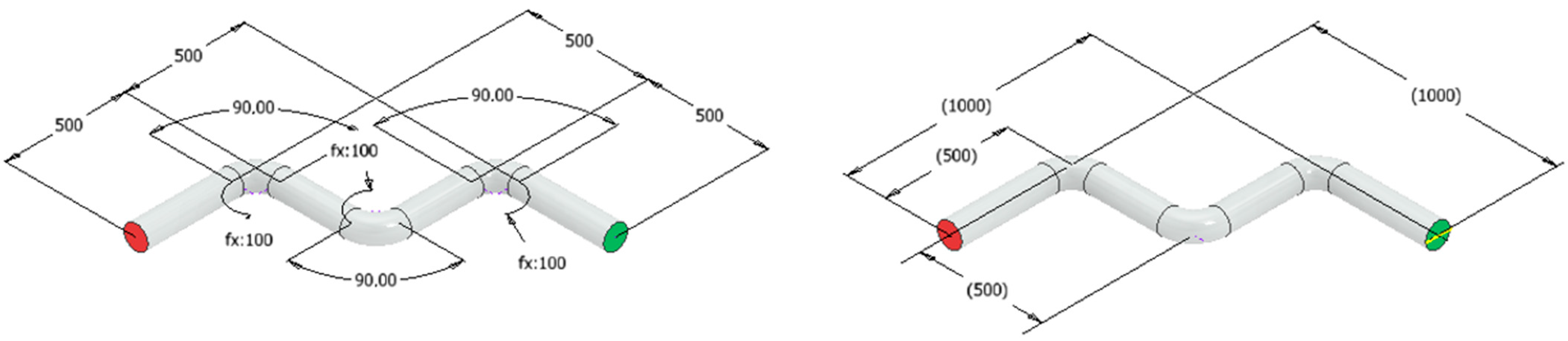
The behavior of the segment templates is controlled by iLogic rules. One rule is necessary to map the corresponding parameters from the routing skeleton, segment template, and the single parts in it after inserting the segment into the routing. Another rule toggles between three preset dimensions, i.e., minimum pipe length to first elbow, elbows in the middle, minimum pipe length to last elbow (
Figure 9), and individual proportions.
The dimensions of the segment template are then used to create a cut list. Based on minimum weldable and maximum buyable pipe lengths, the strait segments of the routing are calculated and divided into the corresponding parts. The individual pipe lengths are also supervised by an automatic manufacturability check. If, e.g., the minimum length is violated, the system generates a message and a suggestion on how to adapt the segment.
3.3.2. Routing Master
The basic components of the routing master assembly (
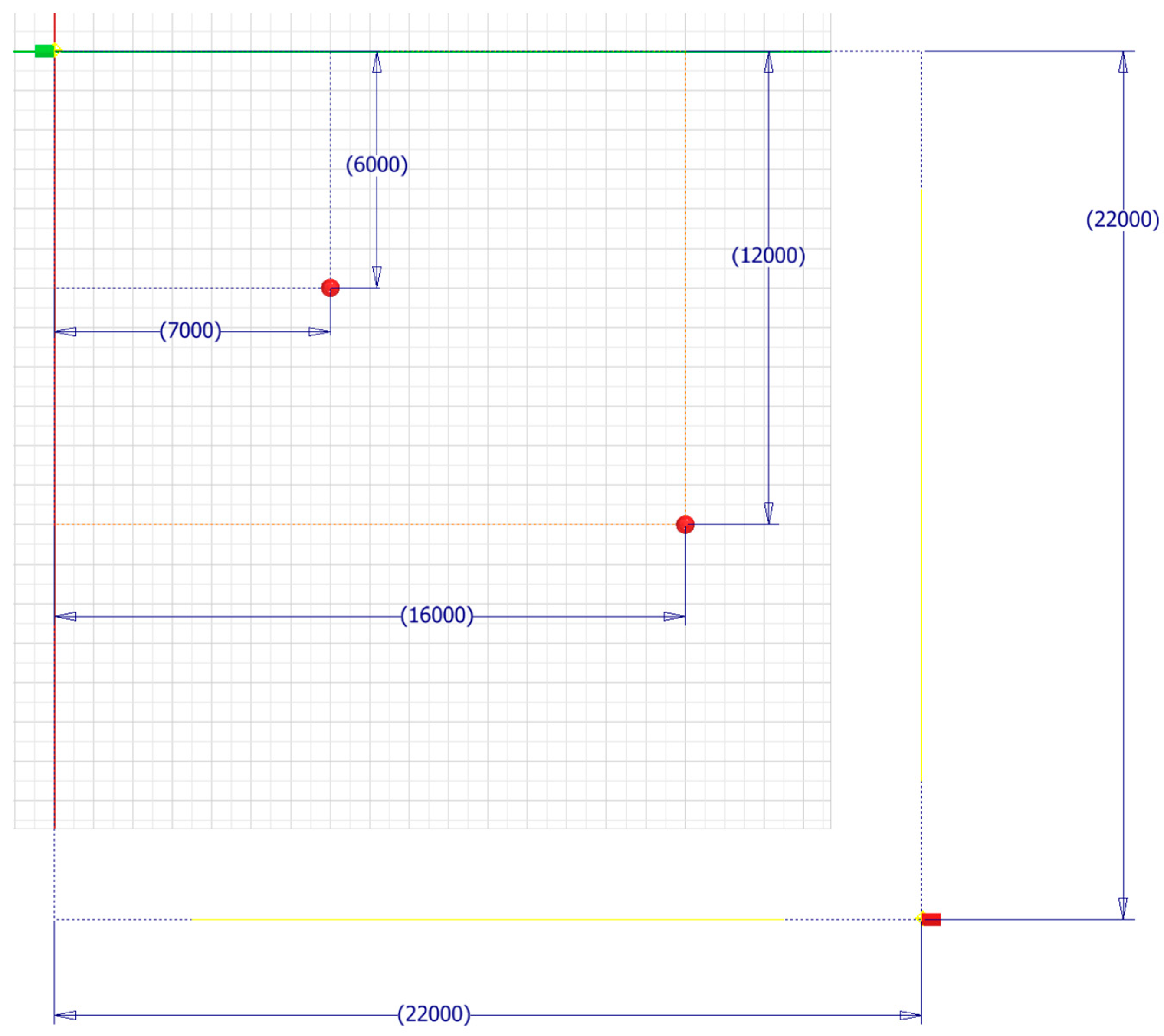
Figure 10) are four work points. The first, to which the starting point marker will be attached, is always located at the assembly origin. The other three markers, two of which are used for setting the positions of the drag points, and one for the end marker, are defined by a sketch, i.e., the routing skeleton, in their respective positions. This skeleton uses just driven reference parameters between the assembly origin and sketch points and is then switched to adaptive to achieve the drag point functionality. For adapting the routing after initial configuration, this sketch needs to be activated, and the corresponding drag point must be moved. The reference parameters are necessary for later constraining, but their value cannot be modified due to the writing protection associated with them. The work points are also fitted with iMates for automatic placement of the drag-balls and the start and end markers according to the workflow defined before. These markers are necessary since work points cannot be picked as contact components with the function
ThisApplication.CommandManager.Pick(SelectionFilterEnum.kAssemblyLeafOccurrenceFilter) to add the predefined routing templates in between.
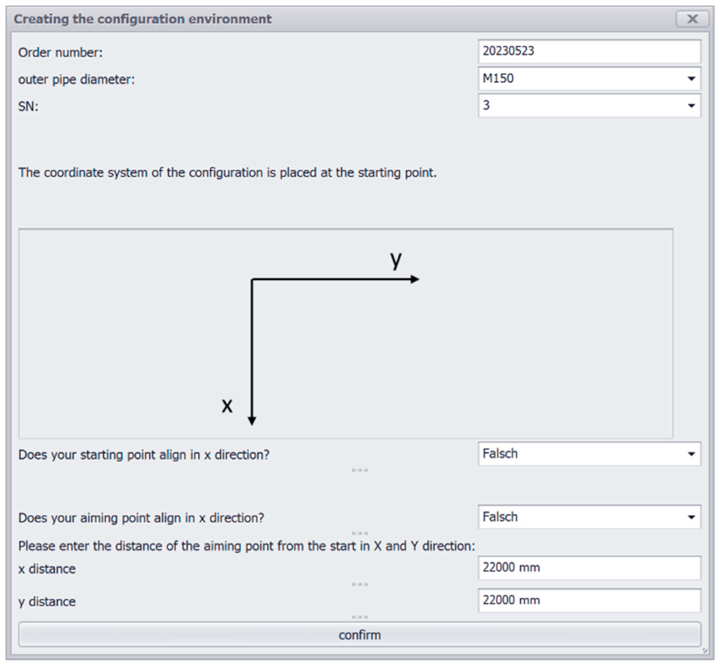
The behavior of the routing master is again controlled by iLogic rules. When a new routing is created, the piping engineer is queried for the basic layout and metadata (see
Figure 11).
3.3.3. Configuring a Routing
After the declaration of the routing, the configuration system automatically assigns the pipe diameters from a spreadsheet containing the standards to each marker and drag ball in the assembly. This would allow the implementation of reducers in a segment in a later version. Additionally, depending on the selected alignment direction for start and end, the rotation parameter is saved.
The next step is to insert the first segment template. The user chooses this from a list and picks the contact components for the start and end. In the background, the configuration system instantiates the template, adjusts its dimensions, creates a separate copy of the sub-assembly, and adds it to the routing assembly. To automatically connect the iMates of the component to the contact components a distinction is made between three cases. The first case is that one of the contacts is the start marker, and the other one is one of the drag-balls. The similar second case has the end marker as one of the contacts. The third case is that both contacts are drag-balls, so the component is to be inserted in the middle of the routing. The contacts are connected using the function AddByiMateAndEntity if the contact is one of the drag-balls. Otherwise, they are connected using the function AddByiMates to which the iMates for the axles and contact surfaces are passed, since this is computationally more efficient. If both contacts are drag-balls further constraints are added to eliminate degrees of freedom.
The alignment from a segment template to a drag-ball can be switched by a rule from collinear to perpendicular and vice versa, which causes the iMates to reassign and the dimensions to update to the new geometric configuration. Additionally, it is possible to change the preset of the segment template.
In case of a modification using the drag-balls, the routing assembly needs to be switched to editing mode, which causes the constraints between the routing skeleton and the assembly work points to be deactivated. The user then interactively adapts the position of the drag-ball and obtains immediate visual feedback from the routing skeleton. If the modification is finished, the routing assembly is switched back to documentation mode, and the constraints are reactivated. The assembly is finally rebuilt.
3.3.4. Interim Conclusion
The implemented technology demonstrator fulfilled the expectations. What remains uncomfortable is the necessity of having a fixed predefined number of drag points in a routing due to the lack of creating new variable instances at runtime. There is no drawback since the number of instruments in the routing can be obtained from the corresponding P&ID diagram. However, if this changes during assembly design, a redesign of parts of the routing would be necessary.
The drag points behave as intended, and the performance of the CAD models with the low level of detail allows for immediate visual feedback. After confirmation, the detailed models are updated, and manufacturability checks are carried out automatically to shorten the loop for engineering department approval.
The technology demonstrator is currently being further developed into a fully featured piping configuration system. Necessary enhancements represent the integration of the slope and compensation check as well as a more detailed declaration of the routings. This is necessary to, e.g., automatically reason about applicable types of compensators depending on media and capacitation.
4. Requirements and Design Features for Graphic Interactive CAD Configuration
Upon completing the design cycle, Hevner’s DSR approach shifts the focus back to the rigor cycle, posing questions about the new knowledge gained from the case and how it contributes to the knowledge base.
Table 1 contains the list of commands that were used during the project in Autodesk Inventor Professional. By taking an inductive approach, this work aims to generalize the requirements and design features that a CAD system must meet to implement graphical interactive configurators.
In addition to the fundamental file managing functions such as opening, closing, saving, determining and setting the file path, and user interaction functions such as generating message prompts, displaying message boxes, opening forms, and input boxes, the capabilities for CAD automation and spreadsheet interaction are particularly significant. The following
Table 2 summarizes functional requirements, design features and implementation alternatives for the application of interactive control elements.
The control of parameters is a foundational function of implementing knowledge-based engineering into CAD models, as stated in the literature. This includes accessing parameters by name, reading and assigning values to them, and using them in equations even across different CAD documents and independently from being assembly or part. In most parametric CAD systems, the user must constrain the geometry in sketches and assemblies properly. However, the case of the routing skeleton demonstrates that controlled degrees of freedom are essential for realizing interactive control elements. Driven parameters were used to evaluate the position of control elements in the routing skeleton’s main sketch and make them available for further processing. The resulting design feature for the requirement of driving parameters by geometry change is to pass control element data to skeleton or component parameters. Implementation variants include the availability of driving and driven parameters such as those shown in the use case, the possibility to temporarily relax or transform driving parameters into driven ones or the possibility to determine, e.g., the position of a drag point by measuring its distances from the assembly origin and write this to the corresponding parameter. Thereby, it is necessary to abstract the control element position either to a given increment or restrict its movement by using a defined grid.
Regarding processing components in an assembly document, it is necessary to control the visibility and suppression state of a component, to add, replace, and delete them. A special case is the addition of components from a part library such as the Inventor content center. When these are designed as part families controlled by a table or spreadsheet, addressing the corresponding variant may require a different query.
Newly introduced components usually need to be constrained in the assembly to avoid unexpected behavior when components are moved. This involves two actions: first to declare the reference for mating and second the addition of the constraints themselves. With respect to the reference component, alternative ways of implementation include selecting the component by clicking in the 3D view or using the feature tree of the CAD system, selecting the reference from a list with the marker IDs or to query them from the user by input boxes. Automatic constraining can be performed via automatically adding constraints between the new component and the assembly origin, using the IDs from geometric elements such as face IDs (note that many parametric CAD system use a chaotic numbering of face IDs, which makes this option less convenient) or using predefined mate features like in the case study.
Coupling an external parameter control can involve, e.g., a spreadsheet application which needs to be linked or embedded with the assembly document or using an external application as remote control for the CAD system. When using spreadsheets as external parameter control, it is important to have the ability to retrieve and change cell values in addition to basic functions such as opening, saving, and closing spreadsheet documents.
Suppressing necessary constraints in a controlled editing mode avoids rebuild errors.
5. Conclusions
Graphical interactive control elements can reduce interaction costs with complex configurable CAD assemblies, but they add additional constraints to the setup of the corresponding CAD documents. To achieve an efficient model rebuild, the case study relied on advanced parameter planning through the use of the extended CommonKADS approach and its correlation model. Additionally, the CAD system must meet specific requirements related to constraining sketches and components in assemblies, addressing parameters and components, and integrating external parameter control and scripting. The case study is exemplary for many modular configuration designs, such as cable routing, conveyors, and suspension monorails, but also infrastructural or building designs like sewage, tunnels, and facades. What they all have in common is that components of the configurable product can be modified in their position or geometry using an abstracted skeleton that can be translated into the drag points.
Functional requirements and design features have been established for Autodesk Inventor Professional, contributing to a reference framework for creating similar control elements in any parametric CAD system with similar functionalities available. The use of the Inventor internal iLogic posed certain restrictions since the scripting language does not allow the creation of new variables at runtime of the rules. Moving the control of parameters and the arrangement of the modular configuration to a higher language can eliminate certain issues, but it can also bring about new challenges in terms of planning workflows and ensuring smooth interaction between the CAD system and the external configuration system. The basic working principle is independent of this.
Author Contributions
Conceptualization, P.C.G. and P.G.; methodology, P.C.G. and P.G.; software, P.G.; validation, P.C.G. and P.G.; formal analysis, P.G.; investigation, P.G.; resources, P.G.; data curation, P.C.G. and P.G.; writing—original draft preparation, P.C.G. and P.G.; writing—review and editing, P.C.G.; visualization, P.G.; supervision, P.C.G.; project administration, P.C.G. All authors have read and agreed to the published version of the manuscript.
Funding
This research received no external funding.
Institutional Review Board Statement
Not applicable.
Informed Consent Statement
Not applicable.
Data Availability Statement
The original contributions presented in the study are included in the article, further inquiries can be directed to the corresponding author.
Conflicts of Interest
The authors declare no conflicts of interest.
References
- Kristjansdottir, K.; Shafiee, S.; Hvam, L. How to identify possible applications of product configuration systems in Engineer-to-Order companies. Int. J. Ind. Eng. Manag. (IJIEM) 2017, 8, 157–165. [Google Scholar] [CrossRef]
- Gembarski, P.C.; Lachmayer, R. Product-Service-Systems: What and why Developers can learn from Mass Customization. Enterp. Model. Inf. Syst. Archit. (EMISAJ) 2018, 13, 16. [Google Scholar] [CrossRef]
- Forza, C.; Salvador, F. Product Information Management for Mass Customization: Connecting Customer, Front-Office and Back-Office for Fast and Efficient Customization; Palgrave Macmillan: Basingstoke, UK, 2006. [Google Scholar] [CrossRef]
- Caetano, I.; Santos, L.; Leitão, A. Computational design in architecture: Defining parametric, generative, and algorithmic design. Front. Archit. Res. 2020, 9, 287–300. [Google Scholar] [CrossRef]
- Gembarski, P.C.; Lachmayer, R. Solution Space Development: Conceptual Reflections and Development of the Parameter Space Matrix as Planning Tool for Geometry-based Solution Spaces. Int. J. Ind. Eng. Manag. (IJIEM) 2018, 9, 177–186. [Google Scholar] [CrossRef]
- Amadori, K.; Tarkian, M.; Ölvander, J.; Krus, M. Flexible and robust CAD models for design automation. Adv. Eng. Inform. 2012, 26, 180–195. [Google Scholar] [CrossRef]
- Skarka, W. Application of MOKA methodology in generative model creation using CATIA. Eng. Appl. Artif. Intell. 2007, 20, 677–690. [Google Scholar] [CrossRef]
- Poot, L.P.; Wehlin, C.; Tarkian, M.; Ölvander, J. Integrating sales and design: Applying CAD configurators in the product development process. Proc. Des. Soc. 2020, 1, 345–354. [Google Scholar] [CrossRef]
- Frank, G.; Entner, D.; Prante, T.; Khachatouri, V.; Schwarz, M. Towards a generic framework of engineering design automation for creating complex CAD models. Int. J. Adv. Syst. Meas. 2014, 7, 179–192. [Google Scholar]
- Felfernig, A.; Hotz, L.; Bagley, C.; Tiihonen, J. Knowledge-Based Configuration: From Research to Business Cases; Newnes: London, UK, 2014. [Google Scholar] [CrossRef]
- Blažek, P.; Kolb, M.; Streichsbier, C.; Honetz, S. The evolutionary process of product configurators. In Managing Complexity: Proceedings of the 8th World Conference on Mass Customization, Personalization, and Co-Creation (MCPC 2015); Bellemare, J., Carrier, S., Nielsen, K., Piller, F.T., Eds.; Springer: Heidelberg, Germany, 2015; pp. 161–172. [Google Scholar] [CrossRef]
- Lam, H. A framework of interaction costs in information visualization. IEEE Trans. Vis. Comput. Graph. 2008, 14, 1149–1156. [Google Scholar] [CrossRef]
- Rind, A.; Aigner, W.; Wagner, M.; Miksch, S.; Lammarsch, T. Task cube: A three-dimensional conceptual space of user tasks in visualization design and evaluation. Inf. Vis. 2016, 15, 288–300. [Google Scholar] [CrossRef]
- Zaky, A.; Zagermann, J.; Reiterer, H.; Feuchtner, T. Opportunities and Challenges of Hybrid User Interfaces for Optimization of Mixed Reality Interfaces. In Proceedings of the 2023 IEEE International Symposium on Mixed and Augmented Reality Adjunct (ISMAR-Adjunct), Sydney, Australia, 16–20 October 2023; IEEE: New York City, NY, USA, 2023; pp. 215–219. [Google Scholar] [CrossRef]
- Seth, A.; Vance, J.M.; Oliver, J.H. Virtual reality for assembly methods prototyping: A review. Virtual Real. 2011, 15, 5–20. [Google Scholar] [CrossRef]
- Gembarski, P.C.; Gast, P. Interactive Geometric Configuration Using Sketch-Based CAD Models. In Proceedings of the 10th International Conference on Mass Customization and Personalization-Community of Europe (MCE-CE 2022), Novi Sad, Serbia, 21–23 September 2022; University of Novi Sad-Faculty of Technical Sciences: Novi Sad, Serbia, 2022; pp. 45–52. [Google Scholar] [CrossRef]
- Ortner-Pichler, A.; Landschützer, C. Integration of parametric modelling in web-based knowledge-based engineering applications. Adv. Eng. Inform. 2022, 51, 101492. [Google Scholar] [CrossRef]
- Hirz, M.; Dietrich, W.; Gfrerrer, A.; Lang, J. Integrated Computer-Aided Design in Automotive Development; Springer: Berlin/Heidelberg, Germany, 2013. [Google Scholar] [CrossRef]
- Demoly, F.; Roth, S. Knowledge-based parametric CAD models of configurable biomechanical structures using geometric skeletons. Comput. Ind. 2017, 92, 104–117. [Google Scholar] [CrossRef]
- Demoly, F.; Toussaint, L.; Eynard, B.; Kiritsis, D.; Gomes, S. Geometric skeleton computation enabling concurrent product engineering and assembly sequence planning. Comput. Aided Des. 2011, 43, 1654–1673. [Google Scholar] [CrossRef]
- Hevner, A.R. A three cycle view of design science research. Scand. J. Inf. Syst. 2007, 19, 87–92. [Google Scholar]
- Zhang, L.L. Product configuration: A review of the state-of-the-art and future research. Int. J. Prod. Res. 2014, 52, 6381–6398. [Google Scholar] [CrossRef]
- Terzidis, K. Algorithmic design: A paradigm shift in architecture. In Proceedings of the 22nd eCAADe Conference, Copenhagen, Denmark, 15–18 September 2004; pp. 201–207. [Google Scholar] [CrossRef]
- Chakrabarti, A.; Shea, K.; Stone, R.; Cagan, J.; Campbell, M.; Hernandez, N.V.; Wood, K.L. Computer-based design synthesis research: An overview. J. Comput. Inf. Sci. Eng. 2011, 11, 021003. [Google Scholar] [CrossRef]
- Brockmöller, T.; Siqueira, R.; Gembarski, P.C.; Mozgova, I.; Lachmayer, R. Computer-aided engineering environment for designing tailored forming components. Metals 2020, 10, 1589. [Google Scholar] [CrossRef]
- Tedeschi, A.; Lombardi, D. The algorithms-aided design (AAD). In Informed Architecture; Springer: Berlin/Heidelberg, Germany, 2018; pp. 33–38. [Google Scholar] [CrossRef]
- Biedermann, M.; Meboldt, M. Computational design synthesis of additive manufactured multi-flow nozzles. Addit. Manuf. 2020, 35, 101231. [Google Scholar] [CrossRef]
- Fuchs, D.; Bartz, R.; Kuschmitz, S.; Vietor, T. Necessary advances in computer-aided design to leverage on additive manufacturing design freedom. Int. J. Interact. Des. Manuf. 2022, 16, 1633–1651. [Google Scholar] [CrossRef]
- Gembarski, P.C. Joining Constraint Satisfaction Problems and Configurable CAD Product Models: A Step-by-Step Implementation Guide. Algorithms 2022, 15, 318. [Google Scholar] [CrossRef]
- Shah, J.J. Designing with parametric cad: Classification and comparison of construction techniques. In International Workshop on Geometric Modelling; Springer: Boston, MA, USA, 1998; pp. 53–68. [Google Scholar] [CrossRef]
- Yao, D.; Chang, Z.Y.; Zhao, J.; Dou, Y.L. Study on key techniques of parametric design system based on solid works and KBE. Appl. Mech. Mater. 2011, 71, 3861–3867. [Google Scholar] [CrossRef]
- Myung, S.; Han, S. Knowledge-based parametric design of mechanical products based on configuration design method. Expert Syst. Appl. 2001, 21, 99–107. [Google Scholar] [CrossRef]
- Gembarski, P.C.; Li, H.; Lachmayer, R. KBE-modeling techniques in standard CAD-systems: Case study—Autodesk inventor professional. In Managing Complexity; Springer: Berlin/Heidelberg, Germany, 2017; pp. 215–233. [Google Scholar] [CrossRef]
- LaRocca, G. Knowledge based engineering: Between AI and CAD. Review of a language based technology to support engineering design. Adv. Eng. Inform. 2012, 26, 159–179. [Google Scholar] [CrossRef]
- Grković, V.; Kolarević, M.; Petrović, A.; Bjelić, M. CAD Configurator for Automatic Configuration of Modular Strongrooms. In Proceedings of the 9th International Conference on Mass Customization and Personalization-Community of Europe (MCE-CE 2020), Novi Sad, Serbia, 23–25 September 2020; University of Novi Sad-Faculty of Technical Sciences: Novi Sad, Serbia, 2020; pp. 85–92. [Google Scholar]
- Peng, C.C.; Rigdway, K. Integration of CAD/CAM and Spreadsheet Data Processing. Integr. Manuf. Syst. 1993, 4, 29–36. [Google Scholar] [CrossRef]
- Marchenko, M.; Behrens, B.A.; Wrobel, G.; Scheffler, R.; Pleßow, M. A new method of visualization and documentation of parametric information of 3D CAD models. Comput. Aided Des. Appl. 2011, 8, 435–448. [Google Scholar] [CrossRef]
- Hoffmann, C.M.; Kim, K.J. Towards valid parametric CAD models. Comput. Aided Des. 2001, 33, 81–90. [Google Scholar] [CrossRef]
- Tang, Z.; Zou, Q.; Gao, S. A decision-support method for multi-parameter editing of parametric CAD models. Adv. Eng. Inform. 2023, 56, 101997. [Google Scholar] [CrossRef]
- Torres, V.H.; Ríos, J.; Vizán, A.; Pérez, J.M. Integration of design tools and knowledge capture into a CAD system: A case study. Concurr. Eng. 2010, 18, 311–324. [Google Scholar] [CrossRef]
- Zheng, P.; Torres, V.H.; Ríos, J.; Zhao, G. Integration of Conceptual Design and MOKA into CATIA v5: A Knowledge-based Application for an Aircraft Y-bolt Component. Appl. Mech. Mater. 2013, 271, 974–980. [Google Scholar] [CrossRef]
- Alarcón, R.H.; Chueco, J.R.; García, J.P.; Idoipe, A.V. Fixture knowledge model development and implementation based on a functional design approach. Robot. Comput. Integr. Manuf. 2010, 26, 56–66. [Google Scholar] [CrossRef]
- Stokes, M. Managing Engineering Knowledge: MOKA: Methodology for Knowledge Based Engineering Applications; Professional Engineering Publishing: London, UK, 2001. [Google Scholar]
- Schreiber, G.; Wielinga, B.; de Hoog, R.; Akkermans, H.; Van de Velde, W. CommonKADS: A comprehensive methodology for KBS development. IEEE Expert 1994, 9, 28–37. [Google Scholar] [CrossRef]
- Schreiber, G.; Akkermans, H.; Anjewierden, A.; de Hoog, R.; Shadbolt, N.; Van de Velde, W.; Wielinga, B. Knowledge Engineering and Management: The CommonKADS Methodology; MIT Press: Cambridge, MA, USA, 2000. [Google Scholar]
- Kingston, J.K. Designing knowledge based systems: The CommonKADS design model. Knowl. Based Syst. 1998, 11, 311–319. [Google Scholar] [CrossRef]
- Park, J.H.; Storch, R.L. Pipe-routing algorithm development: Case study of a ship engine room design. Expert Syst. Appl. 2002, 23, 299–309. [Google Scholar] [CrossRef]
- Qu, Y.F.; Jiang, D.; Zhang, X.L. A new pipe routing approach for aero-engines by octree modeling and modified max-min ant system optimization algorithm. J. Mech. 2018, 34, 11–19. [Google Scholar] [CrossRef]
- Kumar, S.S.; Cheng, J.C. A BIM-based automated site layout planning framework for congested construction sites. Autom. Constr. 2015, 59, 24–37. [Google Scholar] [CrossRef]
- Rodrigues, G.P.W.; Costa, L.H.M.; Farias, G.M.; de Castro, M.A.H. A Depth-First Search Algorithm for Optimizing the Gravity Pipe Networks Layout. Water Resour. Manag. 2019, 33, 4583–4598. [Google Scholar] [CrossRef]
- Calixto, E.E.; Bordeira, P.G.; Calazans, H.T.; Tavares, C.A.; Rodriguez, M.T. Plant design project automation using an automatic pipe routing routine. Comput. Aided Chem. Eng. 2009, 27, 807–812. [Google Scholar] [CrossRef]
- Blokland, M.; van der Mei, R.D.; Pruyn, J.F.J.; Berkhout, J. Literature Survey on Automatic Pipe Routing. Oper. Res. Forum 2023, 4, 35. [Google Scholar] [CrossRef]
| Disclaimer/Publisher’s Note: The statements, opinions and data contained in all publications are solely those of the individual author(s) and contributor(s) and not of MDPI and/or the editor(s). MDPI and/or the editor(s) disclaim responsibility for any injury to people or property resulting from any ideas, methods, instructions or products referred to in the content. |
© 2024 by the authors. Licensee MDPI, Basel, Switzerland. This article is an open access article distributed under the terms and conditions of the Creative Commons Attribution (CC BY) license (https://creativecommons.org/licenses/by/4.0/).


