Article

Application of 3D Imaging for Analyzing the Chip Groove Shapes of Cutting Inserts

by
Grzegorz Struzikiewicz
Faculty of Mechanical Engineering and Robotics, AGH University of Science and Technology, al. Mickiewicza 30, 30-059 Cracow, Poland
Appl. Sci. 2024, 14(7), 3134; https://doi.org/10.3390/app14073134
Submission received: 29 February 2024 / Revised: 2 April 2024 / Accepted: 4 April 2024 / Published: 8 April 2024
(This article belongs to the Special Issue Applications of Vision Measurement System on Product Quality Control)

Abstract

:
An effective chip formation process is significant for an efficient metal-cutting process. Long continuous chips can lead to scratches on the machined surface, increasing the risk to operator safety and stability of the machining process. The use of chip grooves on cutting inserts allows for control of the chip formation and breaking process during machining. The shape of the rake surface and the design of the chip groove also affect the efficiency of the machining process. The article presents the use of 3D imaging to analyze changes in the selected chip groove shapes depending on the cutting depth ap = 0.10, 0.25, and 0.50 mm and the angular location of the cutting insert relative to the machined surface of the workpiece (i.e., major cutting-edge angle K = 60° and K = 90°). The analysis methodology was based on the use of 3D image registration and surface shape modeling. In the analysis based on the 3D imaging presented, the novelty was the adaptation of methods typically used to map and model the terrain surface, which have not been used previously in cutting processes. The evaluation of the shape of the chip groove surface was carried out using, e.g., watershed maps and 3D surface maps. The obtained results indicated a significant influence of the cutting depth and major cutting-edge angle on the surface shape, profile, and length of the chip former; chip groove volume; and the theoretical contact area of the formed chip with the cutting insert. It was observed that for small depths of cut, i.e., ap < 0.25 mm, the chip-curling process may be difficult due to the flattened shape of the rake surface. In addition, the influence of the convexity of the rake surface of the cutting insert on the chip formation process was demonstrated. The results of the experimental research that verified the conclusions are presented. The developed results may be useful in the process of selecting the parameters and conditions of the metal finishing through use of tools with a shaped rake surface.

1. Introduction

One of the most commonly used subtractive machining methods for the manufacture of machine parts is machining. It is widely used due to its ability to shape objects with complex geometries while maintaining high-dimensional accuracy and surface quality. On the other hand, material waste and long operating cycles are cited as machining disadvantages. The basis of machining is the removal of layer after layer of excess material from the workpiece in successive work passes of the cutting tool in order to obtain the desired shape of the part, dimensions, and properties characterizing the surface layer [1,2]. The layers cut in the machining process are transformed into waste material, i.e., chips. Chips affect the surface quality of the workpiece, the manner and the course of wear of cutting tools, and the stability of the machining process.
The morphology and process of chip formation are influenced by the following factors [3,4]:
-
Properties and chemical composition of the workpiece material;
-
The type and geometry of the cutting tool and the shape of the rake face;
-
Accepted values of the cutting data;
-
Physical phenomena occurring in the cutting zone, e.g., the built-up edge on the cutting edge;
-
Type and degree of wear of the cutting edge;
-
Method of cooling the cutting zone and type of coolant and lubricating fluid;
-
The type of tool material and coatings applied to the tools.
From a simplified perspective, chips can be distinguished as correct, acceptable, or unacceptable. Preferred chips are short, fine, and usually similar in shape to the letter “C”. Long, ribbon-like, or spiral and often tangled types are unacceptable, as they can have a destructive effect on the quality of the machined surface and cause catastrophic tool wear. The acceptable form of chips can be characterized by chips that are unacceptable but with acceptable dimensions, e.g., length or diameter, while mixed chips appear when correct and unacceptable chips are produced in the cutting process at the same time [5].
With regard to the breaking mechanism, there are three types of chips: self-breaking, brittle in contact with the tool, and brittle in contact with the workpiece. Important factors influencing chip breaking are the direction of flow of the chip and its curvature. The direction of flow of the chips is a determining factor in chip breaking, as it affects both the curvature of the chips and their orientation. During cutting, the bending torque and the friction at the chip–tool interface affect the radius of the curvature of the chip. A smaller radius of the curvature of the chip results in stronger chip cracking and breaking [6].
The shaping of the rake face of cutting tools (the so-called chip groove) is intended to force the way the chip flows toward the clearance surface or the unmachined surface of the workpiece. When the chip hits an obstacle, i.e., a clearance or unmachined surface, it cracks and breaks. This results in a direct change of unacceptable chips to the correct form. Due to its function, this shape of the rake face is called a “chip retractor” [7].
However, the so-called “chip breakers” found in tool construction are most often used for the direct breaking of long, continuous chips. Studies have shown that the depth and width of the chip breaker have a significant impact on the outcome of the chip-breaking process. It was found that as the depth increases and the breaker width decreases, the chip-breaking efficiency in finishing is improved, and as the depth decreases and the width increases, the chip-breaking efficiency in roughing improves [8]. Due to the fact that the geometry of chip breakers has a positive effect on the machinability of materials, they are also used in drilling and even milling processes. In milling, the geometries of the chip breakers have no effect on cutting forces, and their use increases the curvature of the chip and significantly improves surface roughness [9]. Continuous chips, on the other hand, are problematic during drilling. The chips formed retain heat in the cutting zone and create problems with chip removal. For better performance and chip control, chip grooves are used on the rake face of the drill [10].
In addition to the above-mentioned solutions, the use of convexities has also been analyzed, as well as various types of texturing of the rake surface. An example would be a high-speed steel tool with convexity shaped by additive technology [11]. Experimental tests of the use of this type of tool in the machining of the AlCu4Mg1 aluminum alloy have shown a positive effect of convexity on chip breaking aimed at improving tribological characteristics at the tool–chip interface by texturing the surface of cutting tools. Another way to influence the direction of chip flow is to apply texture to the rake face of the tools. The authors of one paper [12] presented an analysis of the turning process with tools made of WC/Co carbide with a texture obtained by laser processing. The influence of texture laying directions in relation to the cutting edge and chip flow was investigated. The results showed that textures can better modify the adhesion of the workpiece to the rake face and help reduce cutting forces compared to a conventional tool. Chip-breaker geometries are the basic and widely used methods of chip breaking. However, despite the benefits of using them, the development and manufacture of a breakable tool are expensive, as it requires additional treatments and processes such as forming, sintering, grinding, and coating.
The use of 3D-vision measurement methods and imaging is present in many areas of industrial production [13]. These types of non-contact measuring systems are used in the processing of plastics, wood, metals, or composite materials [14,15]. In the area of machining, 3D measurement techniques are most widely used to measure the dimensions and wear of cutting tools and to measure the dimensional accuracy and surface quality of workpieces. Currently, the aim is to measure workpieces and cutting tools directly on numerically controlled machine tools, as well as to integrate measuring systems with CAD/CAM/CAE systems (computer-aided design, computer-aided manufacturing, computer-aided engineering) [16]. An overview of the topic concerning the determination of measurement uncertainty on machine tools and sources of error has been presented previously [17]. For the control and evaluation of the quality of products after the end of the production process, the role of vision systems is most often related to the indication of parameters and the quality features of the analyzed items. The choice of measurement method and system, as well as the type of sensors used, depends on the manufacturing industry. For example, some authors described the inspection of the dimensions and material defects on the surface of the wood using 3D images [18]. Other authors have described using 3D surface images in the field of flatness control of welded parts made of aluminum [19]. Additionally, the analysis of the use of 3D scanning for dimensional control of details obtained in the cutting process is presented in [20].
With regard to cutting tools, the issues that researchers address are most often related to measuring cutting-edge wear. A new methodology for measuring insert wear in turning 1C45 steel and an analysis of errors made by researchers during measurements are presented in [21]. In [22], an innovative measurement procedure is presented for direct spatial measurement of cutting-tool wear using a laser profile sensor. A special system for mounting the measuring device on the turret of the machine tool was designed, and the influence of the orientation of the measuring head on the accuracy and quantity of the obtained measurement data was investigated. In addition, the problem of using 3D images in the task of automated measurement and evaluation of the degree of wear of Qubitron II grinding wheels is presented in [23].
The problems related to the shape of chip retractors and chip breakers found in cutting tools are the most frequently examined by researchers in relation to the methods of control and simulation of the chip-forming or chip-breaking process, as well as the design of chip breakers [24]. Controlling the process of chip formation and chip form is particularly relevant to the processing of bloody materials of difficult-to-cut materials. In [25,26], the authors present an analysis of the effectiveness of using a special chip-breaker design when machining the Inconel 718 alloy. Another area related to the design of chip-breaker structures is the use of computer simulation. In [27], an analysis of the influence of chip-breaker parameters on the radius of curvature of the chip winding is presented. Chip forces and chip-breaking processes were analyzed using a PCD (polycrystalline diamond) tool with a chip breaker. Additionally, the influence of various aspects of chip-breaker geometry on cutting force, chip shape, and bending moment using finite element and experimental methods is presented in [28]. The machining process of AISI 1045 steel was analyzed using tungsten carbide inserts with different chip-breaker geometries. Another example of research that involved finite element design is presented in [9]. This analysis was carried out to evaluate the effectiveness of different chip-breaker designs under milling conditions of Al A356 aluminum alloy. The shape of the chip breaker was produced with laser ablation. In the literature on cutting difficult-to-cut materials, one can find papers in which the physical phenomena occurring in the cutting zone were analyzed in turning and milling processes [29]. Cutting forces, cutting-edge wear processes, and processes affecting the quality of the machined surface have mainly been analyzed. In this context, the form of chips and their morphology have also been analyzed. For example, the authors of [30,31] investigated the use of tools made of superhard materials and tool coatings. Many works also focus on methods for achieving high productivity and cutting efficiency [32,33,34], as well as on ways to predict the values characterizing the cutting processes of difficult-to-cut materials [35].
The analysis of the literature has shown that there are insufficient descriptions of the test results for the use of 3D measurements of the rake surface with a shaped chip groove. Similarly, cutting tool manufacturers do not provide users with sufficient information on the shapes of chip breakers or chip retractors. For this reason, an attempt was made to analyze the use of 3D imaging to determine changes in chip groove shape and profile as a function of cutting data. A novelty in the development of results using 3D imaging was adoption of methods typically used for the mapping and modeling of the terrain surface for machining applications. The influence of the depth of cut and the major cutting-edge angle, which determines the position of the insert in relation to the workpiece, was taken into account. The results of experimental research verifying the conclusions developed with the use of 3D imaging are also presented.

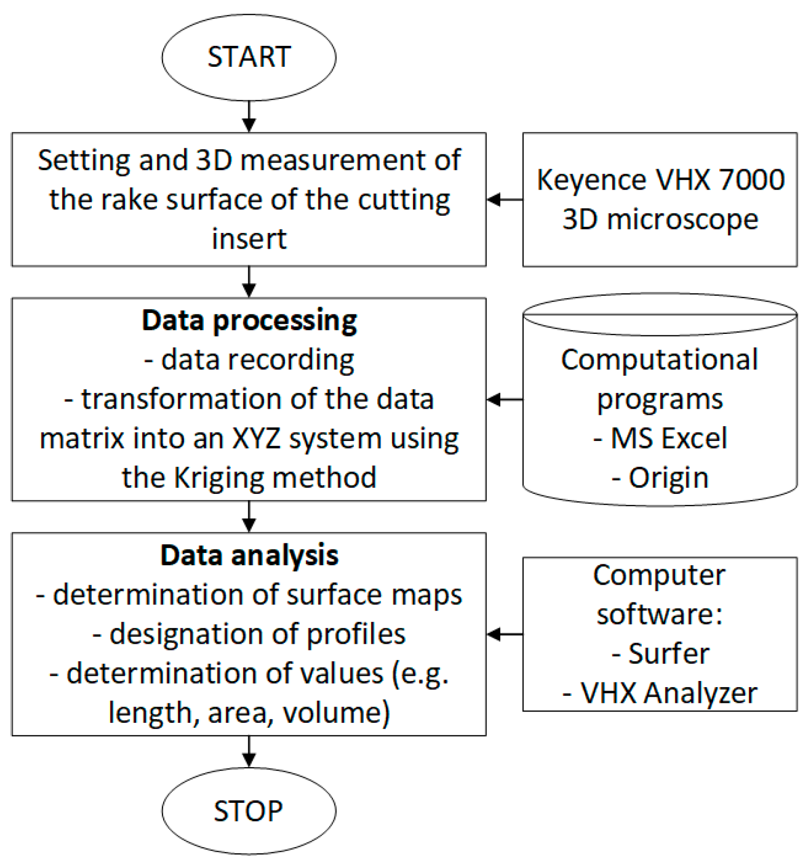
2. Materials and Methods

Three-dimensional imaging of the rake face of the inserts was carried out using a VHX 7000 (Keyence Corporation, Osaka, Japan) measuring microscope with dedicated Keyence software (Analizator VHX-7000_970F, version 1.4.17.3). The measurements were carried out at a constant magnification, i.e., 300×. The option of combining multiple images (7 × 7 image composition) was used with a constant recording of 150 images in the Z-axis. The adopted method allowed for the recording of the measurement data in the form of a matrix with dimensions of about 8268 rows by 10,668 columns. The conversion of data to the XYZ system was carried out using the Kriging algorithm. The range of minimum and maximum heights (upper limit–lower limit) was set manually for each measurement. The basic technical data of the measuring microscope are presented in Table 1. To analyze the measurement results, software dedicated to the microscope and Surfer software (Surfer 2024, version 26.3.269) from Golden Software were used. Figure 1 presents the methodology of the measurements. Some of the calculations and data transformations, e.g., conversion of data in the form of a matrix to the XYZ system, were performed in Origin (OriginPro 2024, version 10.1.0.178) and MS Excel (Microsoft® Excel® for Microsoft 365 MSO, version 2402).
Two types of inserts manufactured by Sandvik Coromant were used in the research, which differed in terms of the shape of the chip breaker on the rake face. Two types of chip breaker were analyzed: SF and SGF. The inserts had the manufacturer’s marking: CNGG120404 (grade 1115) and CNMG120404 (grade H13A). Two cases of setting the cutting insert in relation to the surface of the workpiece were analyzed; that is, for the range of angle values K = 60° and K = 90°. This range covers the clamping range of inserts in tool holders recommended by the tool manufacturer. The inserts and the shape of the chip formers are shown in Table 2.
Inserts are recommended for machining difficult-to-cut materials, such as nickel and titanium alloys. Both tested inserts featured a reinforced cutting edge to protect against notch wear and a reinforced corner radius. The positive rake angle reduces cutting forces, which extends tool life.
During the tests, the analysis was carried out, and the shape profiles of the chip former were determined for three values of depth of cut ap and two values of major cutting-edge angle K. The values of the variables are summarized in Table 3.
In addition, vector map analysis was performed to determine the size and slope of the chip-breaker surface slopes. The theoretical surface area and contact length of the formed chip with the cutting tool material were also analyzed.
In order to verify the results obtained from the theoretical analysis and with the use of 3D imaging, experimental studies were conducted. A plan of experimental research according to the Taguchi method was adopted. The variables were the depth of cut ap, feed f, major cutting-edge angle K, and the type of chip former. The eight research systems were determined. Table 4 presents the test plan and the assumed real values for individual test systems. The cutting data values used in the cutting tests were within the range recommended by the tool manufacturer. The tests were carried out under dry-machining conditions and at a constant speed cutting value of vc = 50 m/min. The machined material tested was titanium alloy Ti6Al4V. The S/N ratio analysis strategy was adopted as “the lowest-best” according to Formula (1).
S / N = 10 · log ( 1 n i = 1 n y i 2 ) ,
The classification of chips was carried out by determining the chip-breaking index Cch. A simplified method was adopted to determine the indicator value depending on the dimension of the chip length Lch. Chips obtained in cutting tests were assigned values between 0 and 1. Lower Cch values represented shorter chips and better chip breakability. In theoretical analyses and experimental studies, the phenomenon of a built-up edge on the cutting edge was not taken into account.

3. Results and Discussion

In accordance with the adopted research methodology, a 3D imaging analysis of the rake surfaces of the tested inserts was performed. The use of selected computer programs for the analysis of the obtained data allowed for the measuring of the geometrical dimensions of selected areas of the cutting edges. In the analysis of the results, various methods of visualization of the measurement data in the 3D system were used. Figure 2 presents examples of visualization of measurement results in a 3D view with the use of selected color palettes in the form of a catchment map and a contour view. A view of the insert corner using a color palette made it possible to determine the areas of elevation and depression that occur on the rake face of the insert. A 3D surface presented in the form of a watershed map enabled the analysis of the volume of the shaped chip groove on the rake face of the insert. Additionally, the contour map view made it possible to interpret the shape of the insert surface and the differences and degree of level build-up for selected areas.
Figure 3 and Figure 4 show examples of the positions of the measuring lines for which the shape of the transverse profile of the chip groove was determined. The profiles were determined in places corresponding to the geometrical dimensions for the depth of cut ap. Profiles were determined for three depths of cut (i.e., ap = 0.1, 0.25, 0.50 mm). Two insert positions corresponding to different inserts were analyzed, corresponding to different ways of clamping the insert in the holder. Two positions were assumed for the of major cutting-edge angle: K = 60° and K = 90°. The drawings schematically show the position of the inserts in relation to the workpiece. The shapes of the obtained profiles are shown in Figure 3b,d for the insert with the SGF chip former and in Figure 4b,d for the insert with the SF chip former.
Observations and measurements based on 3D imaging showed a different structure of the rake face and chip groove of the analyzed inserts. Generally, the cutting-edge area of the SGF chip-former insert had a more convex design compared to the SF chip-former insert. In the case of the SF breaker insert, the chip groove position was parallel to the cutting edge and had a similar profile shape and large depth and volume. The maximum level difference between the bottom of the groove and the tip of the groove was about 400 μm regardless of the angle at which the insert was clamped in the tool holder. With the SGF chip breaker, the surface shape of the chip groove varied along the cutting edge. This was due to the use of notch reinforcement on the cutting edge against wear. In general, the depth of the chip groove was about half that of the SF breaker (the difference between the bottom of the chip groove and its top was about 200 μm).
The analysis of the results showed a variability in the shape of the chip-former profile as a function of the depth of cut. For small depths of cut (ap = 0.1 mm) for both inserts tested, the shapes of the designated surface profiles were flattened and located highest in relation to the insert base plane. This was due to the value of the rake angle of the rake face of γ = 15° for the cutting tools analyzed. On the other hand, the lengths of the designated profiles depended on the value of the angle K. The highest values of profile lengths were obtained for the angle K = 90° (for example, the profile length for the depth ap = 0.1 mm was more than twice as large as the profile length for K = 60°). The shape of the chip-breaker profile (visible convexity and elevation angle) was fundamentally changed from a depth of ap = 0.25 mm. Thus, chip formation during machining can be difficult in this area of the cutting edge. The full shape of the chip breaker with its large depth and level difference was visible for depths of cut above ap = 0.5 mm. This was particularly noticeable for the SF insert.
Figure 5 and Figure 6 show examples of measurements of the theoretical chip contact length with the rake face of the insert. The Lch value was measured along the profile of the chip retractor. The results indicate a significant influence of the major cutting-edge angle K. In the case of an insert with the SF chip former, for an angle of K = 60°, the length of the chip contact along the chip retractor profile was similar and did not depend significantly on the depth of cut (Lch ≈ 0.44–0.39 mm). On the other hand, for an angle K = 90° and a depth of cut ap = 0.1 mm, the Lch value was more than twice as high. This is due to the flattened shape of the rake face surface of the cutting edge. In this case, theoretically, the chips are poorly susceptible to the curling process and can theoretically move along the entire rake surface. To improve the chip-curling process, the cutting depth should be increased, which would result in a more accurate filling of the chip groove by the chip material and a shortening of the contact between the chip and the tool. Furthermore, for the cutting insert with an SGF chip former, a decrease in the length of contact between the chip and tool was observed for a depth of cut above ap > 0.25 mm regardless of the assumed value of the angle K. However, it should be noted that the chip-to-tool contact lengths were larger (about two times on average) than those for the insert with the SF chip former. The variable shape of the profile, and thus the theoretical contact length between the chips and the cutting edge, was due to the convex structure that reinforced the insert structure. It should be added that, in practice, chip forming can be carried out on a shorter section, i.e., on the first concave shape of the chip former.
Figure 6 shows an example of the measurements of the theoretically maximum chip displacement area on the rake face and the volume of the chip groove. It has been observed that both the theoretical contact area of the chips with the cutting edge and the volume of the chip former depend on the depth of cut. A comparative analysis of the measurement results showed that higher values were obtained for inserts with an SGF chip former than for inserts with an SF chip former (from about 1.5 to more than 3 times higher) regardless of whether the major cutting-edge angle K was adopted.
Figure 7 shows examples of the insert cutting-edge areas with vector maps. Analysis of the measurements showed that for the insert with the SF breaker behind the cutting edge, there was a slope of the breaker surface over a large area and that the flow of the created chip was in the direction parallel to the cutting edge moving into the chip groove. This surface shape promoted chip wrapping and chip evacuation away from the workpiece. This process was also facilitated by the steep slope of the back wall of the chip breaker (the longer length of the vectors is shown in Figure 7a). For higher feed rates, the back wall of the chip groove can also be used as a chip breaker. Moving the chip material against the back wall at a higher speed can cause stress build-up and cracks in the material. On the other hand, in the case of the insert with the SGF breaker, the vectors on the front and back surfaces of the chip groove had similar lengths and were directed in opposite directions. This indicates a strengthening of the chip-curling process. Figure 8 shows examples of chip photography obtained in the cutting tests of Inconel 625. For small depths of cut (ap = 0.25 mm/rev) and feed rate (f = 0.07 mm/rev), the chips were in the form of a ribbon-like shape. With increased values of depth of cut and feed, an intensification of the process of chip curling (smaller distances between chip turns—Figure 8b) to a spiral form was observed (an example of a long spiral form of chips is shown in Figure 8c).
Figure 9 shows an example of a microscopic photographs of the rake face of the inserts under testing, with visible marks (marked with a red line) obtained due to the friction of the chip against the cutting tool material. Analysis of the shape and surface of the marks showed a different direction of chip formation depending on the angle of the tool in relation to the workpiece material. For the major cutting-edge angle K = 60°, within the range of the tested depths of cut, the formed chips filled the chip groove to a greater extent. In addition, the observed wear on the back wall of the chip former indicates an increased contribution of this surface to the chip-rolling process. Additionally, a comparison of chip-former types showed smaller wear surfaces for the SF type than for the SGF type. This indicates a higher intensity of the chip-rolling process. For a depth of cut ap = 0.25 mm, the wear surface had an elongated shape and was largely parallel to the machined surface. It follows that for such depths of cut, the chip form can change and be characterized, for example, by larger distances between chip turns or a change from a helical to a ribbon form. It was also observed that for both tested chip-former shapes, the increase in feed rate increased the degree of chip groove filling.
Table 5 presents the results of the average values of the breakage coefficient of Cch chips, with a description of the shape of the chips, and values of the S/N parameter obtained in the test systems. A simplified method of chip classification was adopted, according to which the chip breakage index Cch takes values from 0 to 1. Lower Cch values represent better chip breakability. Table 6 presents a statistical analysis of the test results.
The analysis of the data showed that the feed rate had the most significant influence on the chip form and the average values of the chip-breaking coefficient Cch in the longitudinal turning process. According to statistical analysis, the parameters with a higher F value had a greater influence on the responses represented in Table 5. Moreover, the depth of cut ap, feed f and major cutting-edge angle K contributed 45.7%, 30%, and 17.6% of the response to the chip-breaking index value Cch when the test alloy was turned. The chip-former type ranked last.
Figure 10 graphically shows the influence of individual variables on the average value of the chip breakability index Cch.
Graphical analysis of the results showed that an increase in the value of cutting parameters, i.e., depth of cut and feed, affects the change of chip form from unfavorable to acceptable and correct. For depths of cut ap < 0.5 mm and low feed rates value, there is no chip-breaking process, and long, unacceptable chips are obtained in the machining process. Further increasing the depth of cut results in an acceptable chip form. The parameter that has the greatest impact on the change in the form of chips is the feed value, as evidenced by the large angle of inclination of the line presented in the diagram. Moreover, a lower major cutting-edge angle (K = 60°) supports the chip-formation process and leads to a more favorable chip form. A small angle of inclination for the types of chip that were tested indicates that in the tested range of factors, the shape of the rake face is influential. The conclusion is that higher values of cutting parameters, such as feed and depth of cut, should be used for the correct operation of the chip formers. For the analyzed types of chip formers, the SF turned out to be more beneficial. The results obtained are consistent with the results of the theoretical analysis carried out with the use of 3D imaging.

4. Conclusions

Based on 3D imaging of the rake face shape and profiles for the two types of chip groove, the following conclusions can be drawn depending on the depth of cut and the major cutting-edge angle of the insert:
-
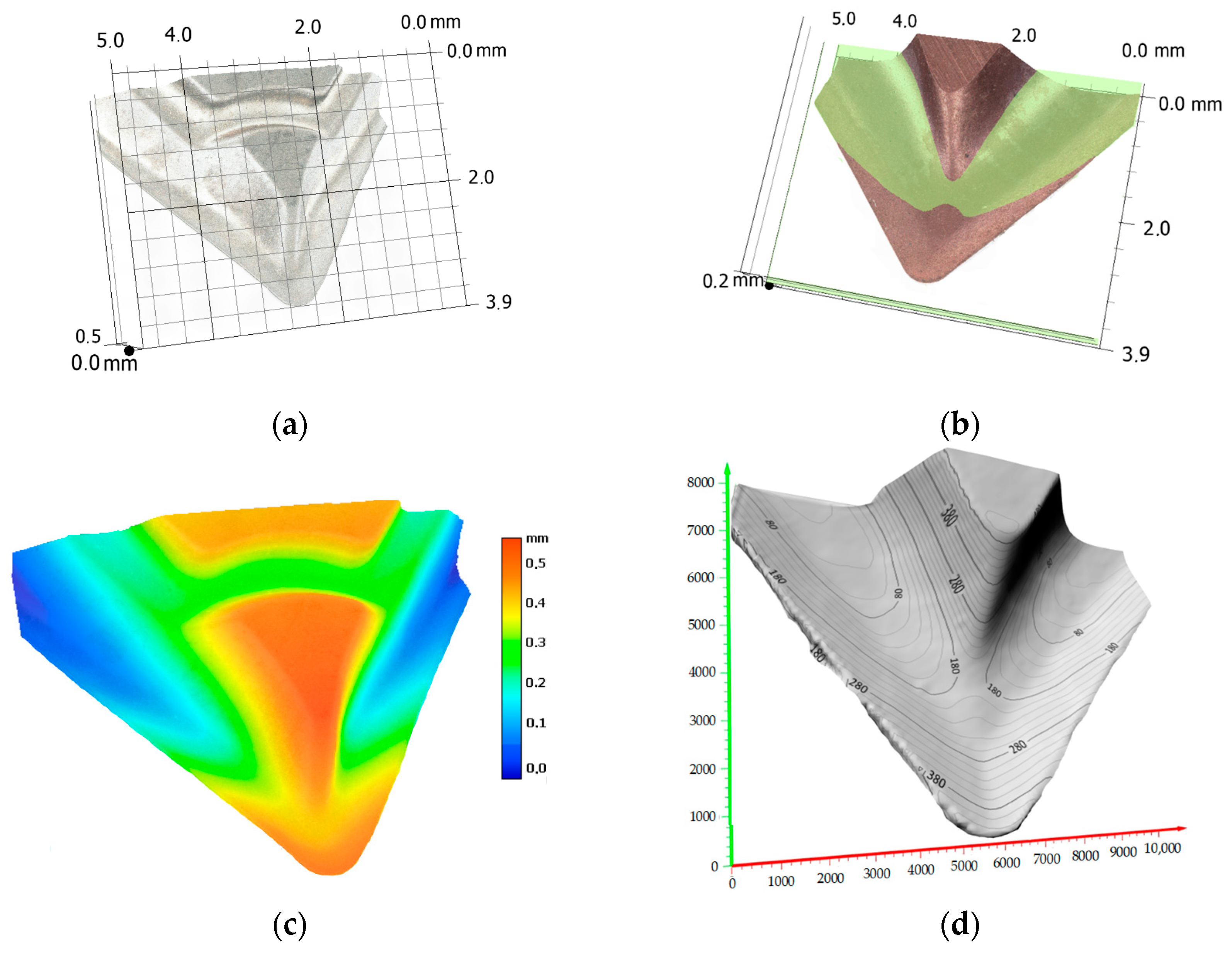
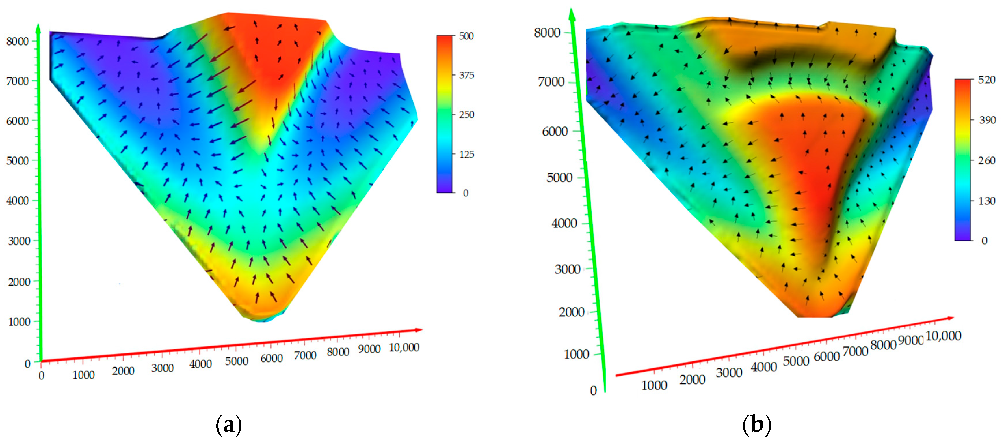
The measurements showed a different structure of the analyzed chip grooves. Inserts with an SGF breaker were mostly convex in design, while inserts with an SF breaker were concave. It was also been observed that the position of the SF breaker was parallel to the cutting edge and was characterized by a similar profile shape and high depth and volume. The maximum level difference between the bottom of the groove and the tip of the groove was about 400 μm regardless of the angle at which the insert was clamped in the tool holder. With the SGF breaker, the surface shape of the chip groove was variable along the cutting edge, and the depth of the chip groove was approximately half the size (about 200 μm) of the SF breaker.
-
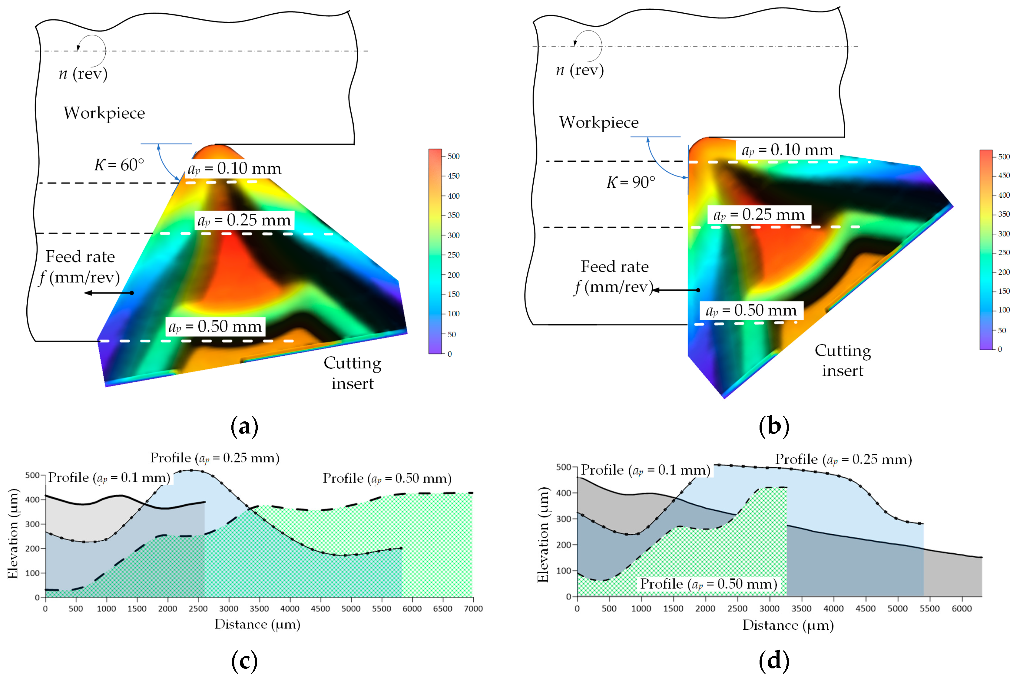
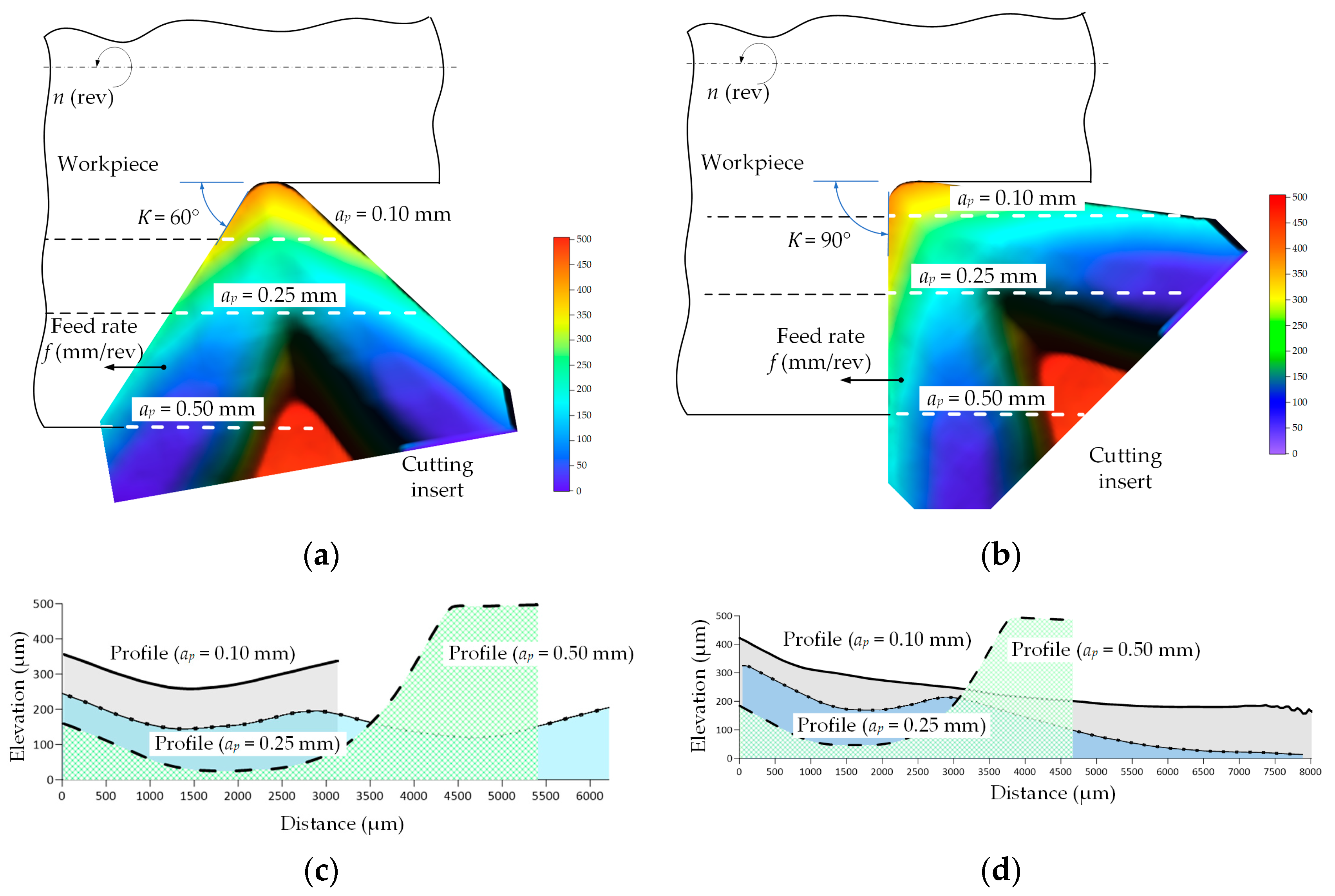
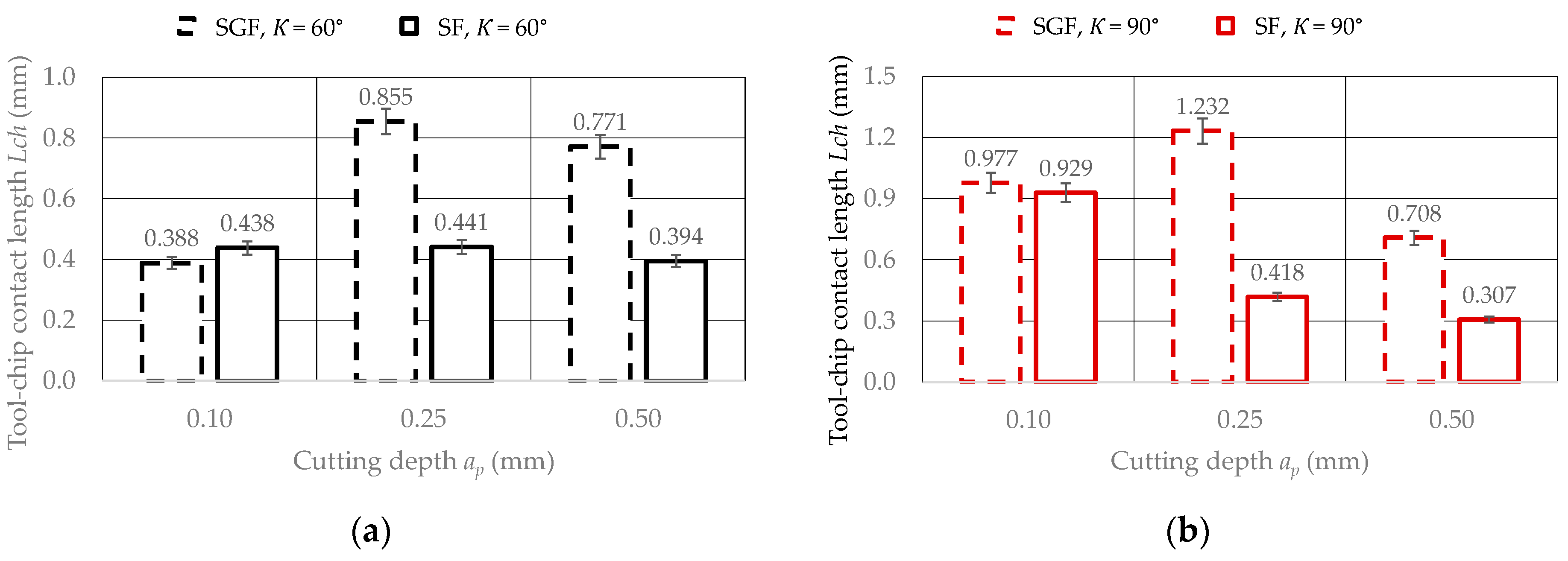
The analysis of the results showed variability of the shape of the breaker profile as a function of the depth of cut. For a depth of cut ap = 0.1 mm, in the case of both tested inserts, the shapes of the determined surface profiles were flattened, and the lengths of the determined profiles depended on the value of the major cutting-edge angle K. The highest values of profile lengths were obtained for the angle K = 90°. The shape of the chip-breaker profile changed the most for ap > 0.25 mm.
-
The theoretical length of the chip contact with the rake face of the insert Lch, significantly depends on the entering the major cutting-edge angle K, as well as on the chip-breaker profile resulting from the given depth of cut. There may be areas where the chips are poorly retracted and can theoretically travel along the entire rake face. To improve the chip-curling process, the depth of cut should be increased, as this can fill the chip groove more accurately with the chip material and reduce chip-to-tool contact.
-
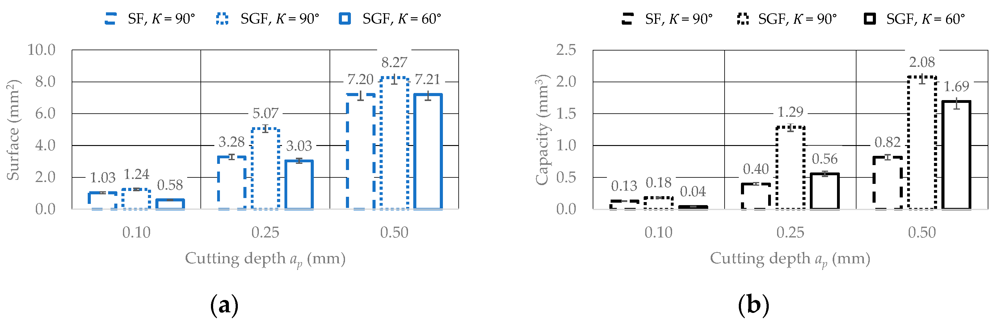
A comparative analysis of the measurement results showed that for inserts with an SGF breaker, higher values of the chip–cutting edge contact area and chip groove volume were obtained than for inserts with an SF chip former (from about 1.5 to more than 3 times higher) regardless of the adopted major cutting-edge angle K.
-
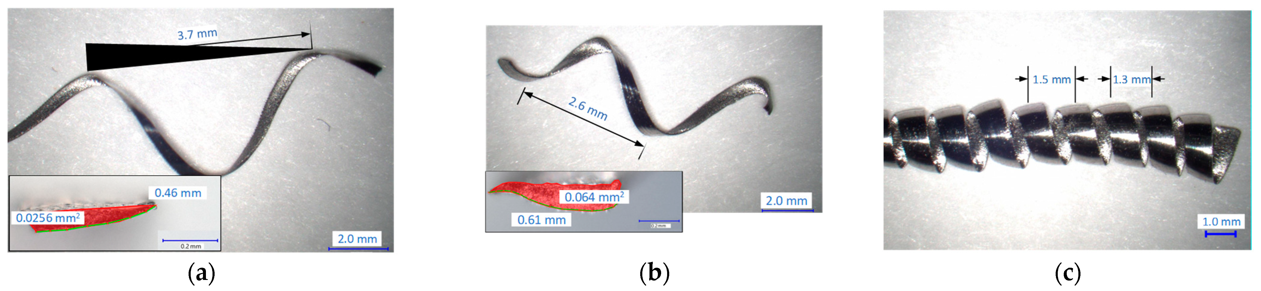
The results obtained from the experimental verification research were consistent with the results of the theoretical analysis carried out with the use of 3D imaging. For the accepted conditions and ranges of cutting parameters, the analysis of the results of experimental tests showed that the form of chips and the average values of the chip-breaking coefficient Cch were most significantly influenced by the value of feed and depth of cut. For a feed of f = 0.1 mm/rev and a depth of cut ap < 0.5 mm, a change in the form of the chips was observed from helical to ribbon. Furthermore, cutting tests showed that the major cutting-edge angle (K = 60°) supported the chip-formation process and led to a more favorable chip form. For the SF chip-former type application, this turned out to be more beneficial, as it more effectively supported the chip-curling process.
-
Obtaining short chips, especially when machining difficult-to-cut materials, reduces manufacturing costs. Long chips that move in the direction of the rotating workpiece significantly increase the possibility of damage to the machined surface. The test results obtained for the accepted cutting conditions showed that controlling the form of the chip is possible by maximizing the feed rate and depth of cut. A practical recommendation for turning titanium alloy Ti6Al4V is to reduce the major cutting-edge angle and to choose the SF chip former, which supports the chip-rolling process.

Funding

This research received no external funding.

Institutional Review Board Statement

Not applicable.

Informed Consent Statement

Not applicable.

Data Availability Statement

The original contributions presented in the study are included in the article, further inquiries can be directed to the corresponding author.

Conflicts of Interest

The author declares no conflicts of interest.

References

  1. Grzesik, W. Advanced Machining Processes of Metallic Materials: Theory, Modelling and Applications; Elsevier: Amsterdam, The Netherlands, 2008. [Google Scholar]
  2. Markopoulos, A.P.; Davim, J.P. Advanced Machining Processes—Innovative Modeling Techniques; CRC Press Taylor & Francis Group: Boca Raton, FL, USA, 2017. [Google Scholar] [CrossRef]
  3. Jawahir, I.S. Chip-forms, Chip Breakability and Chip Control. In CIRP Encyclopedia of Production Engineering; Laperrière, L., Reinhart, G., Eds.; Springer: Berlin/Heidelberg, Germany, 2014. [Google Scholar] [CrossRef]
  4. Das, A.; Padhan, S.; Das, S.R.; Alsoufi, M.S.; Ibrahim, A.M.M.; Elsheikh, A. Performance Assessment and Chip Morphology Evaluation of Austenitic Stainless Steel under Sustainable Machining Conditions. Metals 2021, 11, 1931. [Google Scholar] [CrossRef]
  5. Słodki, B.; Zębala, W.; Struzikiewicz, G. Correlation between cutting data selection and chip form in stainless steel turning. Mach. Sci. Technol. 2014, 19, 217–235. [Google Scholar] [CrossRef]
  6. Yılmaz, B.; Karabulut, S.; Güllü, A. A review of the chip breaking methods for continuous chips in turning. J. Manuf. Process. 2020, 49, 50–69. [Google Scholar] [CrossRef]
  7. Nakayama, K. A study on chip-breaker. Bull. JSME 1962, 5, 142–150. [Google Scholar] [CrossRef]
  8. Kim, J.D.; Kweun, O.B. A chip-breaking system for mild steel in turning. Int. J. Mach. Tools Manuf. 1997, 37, 607–617. [Google Scholar] [CrossRef]
  9. Elkaseer, A.; Lambarri, J.; Ander Sarasua, J.; Cascón, I. On the development of a chip breaker in a metal-matrix polycrystalline diamond insert: Finite element based design with ns-laser ablation and machining verification. J. Micro Nano-Manuf. 2017, 5, 031007. [Google Scholar] [CrossRef]
  10. Sahu, S.K.; Burak Ozdoganlar, O.; DeVor, R.E.; Kapoor, S.G. Effect of groove-type chip breakers on twist drill performance. Int. J. Mach. Tools Manuf. 2003, 43, 617–627. [Google Scholar] [CrossRef]
  11. Shi, C.; Yu, A.; Wu, J.; Niu, W.; He, Y.; Hong, X.; Shang, Q. Study on position of laser cladded chip breaking dot on rake face of HSS turning tool. Int. J. Mach. Tools Manuf. 2017, 122, 132–148. [Google Scholar] [CrossRef]
  12. Vasumathy, D.; Meena, A.; Duraiselvam, M. Experimental study on evaluating the effect of micro textured tools in turning AISI 316 austenitic stainless steel. Procedia Eng. 2017, 184, 50–57. [Google Scholar] [CrossRef]
  13. Anand, S.; Priya, L. A Guide for Machine Vision in Quality Control; CRC Press Taylor & Francis Group: New York, NY, USA, 2020. [Google Scholar] [CrossRef]
  14. Sansoni, G.; Trebeschi, M.; Docchio, F. State-of-The-Art and Applications of 3D Imaging Sensors in Industry, Cultural Heritage, Medicine, and Criminal Investigation. Sensors 2009, 9, 568–601. [Google Scholar] [CrossRef] [PubMed]
  15. Sioma, A. 3D Imaging Methods in Quality Inspection Systems. In Proceedings of the Photonics Applications in Astronomy, Communications, Industry, and High-Energy Physics Experiments, Wilga, Poland, 26 May–2 June 2019; Romaniuk, R.S., Linczuk, M., Eds.; SPIE: Bellingham, WA, USA, 2019; p. 91. [Google Scholar] [CrossRef]
  16. Kyratsis, P.; Kakoulis, K.; Markopoulos, A.P. Advances in CAD/CAM/CAE Technologies. Machines 2020, 8, 13. [Google Scholar] [CrossRef]
  17. Mutilba, U.; Gomez-Acedo, E.; Kortaberria, G.; Olarra, A.; Yagüe-Fabra, J.A. Traceability of On-Machine Tool Measurement: A Review. Sensors 2017, 17, 1605. [Google Scholar] [CrossRef] [PubMed]
  18. Cinal, M.; Sioma, A.; Lenty, B. The Quality Control System of Planks Using Machine Vision. Appl. Sci. 2023, 13, 9187. [Google Scholar] [CrossRef]
  19. Sioma, A.; Karwat, B. The Use of 3D Imaging in Surface Flatness Control Operations. Adv. Sci. Technol. Res. J. 2023, 17, 335–344. [Google Scholar] [CrossRef] [PubMed]
  20. Lazarević, D.; Nedić, B.; Jović, S.; Šarkoćević, Ž.; Blagojević, M. Optical inspection of cutting parts by 3D scanning. Phys. A Stat. Mech. Its Appl. 2019, 531, 121583. [Google Scholar] [CrossRef]
  21. Daicu, R.; Oancea, G. Methodology for Measuring the Cutting Inserts Wear. Symmetry 2022, 14, 469. [Google Scholar] [CrossRef]
  22. Čerče, L.; Pušavec, F.; Kopač, J. 3D cutting tool-wear monitoring in the process. J. Mech. Sci. Technol. 2015, 29, 3885–3895. [Google Scholar] [CrossRef]
  23. Sioma, A.; Struzikiewicz, G. Measurement of wear level of Qubitron II grinding wheels with using 3D vision system. In Proceedings of the Photonics Applications in Astronomy, Communications, Industry, and High-Energy Physics Experiments, Wilga, Poland, 3–10 June 2018; Romaniuk, R.S., Linczuk, M., Eds.; SPIE: Bellingham, WA, USA, 2018; p. 55. [Google Scholar] [CrossRef]
  24. Shinozuka, J.; Obikawa, T.; Shirakashi, T. Chip breaking analysis from the viewpoint of the optimum cutting tool geometry design. J. Mater. Process. Technol. 1996, 62, 345–351. [Google Scholar] [CrossRef]
  25. Güllü, A.; Karabulut, Ş.; Güldaş, A. Chip breaking problems in machining of Inconel 718 super alloy and chip breaker design. J. Fac. Eng. Archit. Gazi Univ. 2008, 23, 157–164. [Google Scholar]
  26. Yılmaz, B.; Karabulut, Ş.; Güllü, A. Performance analysis of new external chip breaker for efficient machining of Inconel 718 and optimization of the cutting parameters. J. Manuf. Process. 2018, 32, 553–563. [Google Scholar] [CrossRef]
  27. Wu, M.; Yu, A.; Chen, Q.; Wang, Y.; Yuan, J.; Sun, L.; Chi, J. Design of adjustable chip breaker for PCD turning tools. Int. J. Mech. Sci. 2020, 172, 105411. [Google Scholar] [CrossRef]
  28. Lotfi, M.; Akhavan Farid, A.; Soleimanimehr, H. The effect of chip breaker geometry on chip shape, bending moment, and cutting force: FE analysis and experimental study. Int. J. Adv. Manuf. Technol. 2015, 78, 917–925. [Google Scholar] [CrossRef]
  29. Li, X.; Wang, Y.; Miao, L.; Zhang, W. Deformation Analysis of Continuous Milling of Inconel 718 Nickel-Based Superalloy. Micromachines 2022, 13, 683. [Google Scholar] [CrossRef] [PubMed]
  30. Persson, H.; Lenrick, F.; Franca, L.; Ståhl, J.E.; Bushlya, V. Wear mechanisms of PcBN tools when machining AISI 316L. Ceram. Int. 2021, 47, 31894–31906. [Google Scholar] [CrossRef]
  31. Fei, H.; Wu, H.; Yang, X.; Xiong, J.; Zhang, L.; Chen, Z.; Jiang, K.; Liu, J. Pulsed magnetic field treatment of cBN tools for improved cutting performances. J. Manuf. Process. 2021, 69, 21–32. [Google Scholar] [CrossRef]
  32. Fountas, N.A.; Papantoniou, I.; Kechagias, J.; Manolakos, D.E.; Vaxevanidis, N.M. Implementation of Modern Meta-Heuristic Algorithms for Optimizing Machinability in Dry CNC Finish-Turning of AISI H13 Die Steel Under Annealed and Hardened States. In Evolutionary Optimization of Material Removal Processes, 1st ed.; Singh, R.P., Kumar, N., Kataria, R., Pandey, P.M., Eds.; CRC Press: Boca Raton, FL, USA, 2022; Volume 3, p. 15. [Google Scholar] [CrossRef]
  33. Fountas, N.A.; Papantoniou, I.; Manolakos, D.E.; Vaxevanidis, N.M. Implementation of Grey Wolf, Multi-Verse and Ant Lion Metaheuristic Algorithms for Optimizing Machinability of Dry CNC Turning of Annealed and Hardened UNIMAX® Tool Steel. Machines 2024, 12, 156. [Google Scholar] [CrossRef]
  34. Vaxevanidis, N.M.; Fountas, N.A.; Papantoniou, I.; Manolakos, D.E. Experimental investigation and regression modelling to improve machinability in CNC turning of CALMAX® tool steel rods. In IOP Conference Series: Materials Science and Engineering, Proceedings of the 6th International Conference on Advanced Manufacturing Engineering and Technologies, Galati, Romania, 9–11 September 2020; IOP Publishing: Bristol, UK, 2020; Volume 968, p. 012012. [Google Scholar] [CrossRef]
  35. Kosaraju, S.; Aruri, D.; Kolli, M.; Kumar, G.S.; Bobba, P.B. Study on machinability of Ti6Al4V with coated inserts—Cutting force, surface finish and material removal rate prediction using ANN. Int. J. Interact. Des. Manuf. 2022, 2022, 1–11. [Google Scholar] [CrossRef]
Figure 1. Diagram of the measurement methodology.
Applsci 14 03134 g001
Figure 2. Three-dimensional imaging examples: (a) general view of the insert corner view with the SGF chip former, (b) corner view of the insert with the SF chip former on the catchment map, (c) a corner view of the insert in the accepted baw palette, and (d) contour view of insert corners with the SF chip former.
Applsci 14 03134 g002
Figure 3. Determination and measurement of the shape of the SGF chip-former profiles. (a) Determination of the chip-former profiles for the insert with the major cutting-edge angle K = 60°. (b) Determination of the chip-former profiles for inserts with K = 90°. (c,d) Dimensions of the SGF chip-former profiles for K = 60° and K = 90°.
Applsci 14 03134 g003
Figure 4. Determination and measurement of the shape of the SF chip-former profiles. (a) Determination of the breaker profiles for the insert with the major cutting-edge angle K = 60°. (b) Determination of breaker profiles for inserts with K = 90°. (c,d) Dimensions of the SF chip-former profiles for K = 60° and K = 90°.
Applsci 14 03134 g004
Figure 5. Comparison of the measurement results of the theoretical tool-chip contact length Lch with the SGF and SF chip-former profile. (a) Tool-chip contact length Lch for inserts with the major cutting-edge angle K = 60°. (b) Tool-chip contact length Lch for inserts with K = 90°.
Applsci 14 03134 g005
Figure 6. Examples of rake surface measurement results. (a) Theoretical chip flow surface on the insert surface. (b) Theoretical volume of the chip groove.
Applsci 14 03134 g006
Figure 7. Insert corner vector maps. (a) Rake face of the insert with the SF chip former. (b) Rake face of the insert with the SGF chip former.
Applsci 14 03134 g007
Figure 8. Photographs and cross sections of chips from the Inconel 625 workpiece material. (a) Chips when cut with the insert with the SGF breaker, with ap = 0.25 mm and f = 0.08 mm/rev. (b) Chips when cut with the insert with the SGF breaker, with ap = 0.50 mm and f = 0.10 mm/rev. (c) Chips when cutting with the insert with the SF chip former, with ap = 0.50 mm and f = 0.20 mm/rev.
Applsci 14 03134 g008
Figure 9. Rake face with visible wear resulting from the contact between the chip and the cutting tool. (a) Rake face of the insert with the SF chip former. (b) Rake face of the insert with the SGF chip former.
Applsci 14 03134 g009
Figure 10. Influence of the analyzed factors on the average values of the chip breakability index Cch.
Applsci 14 03134 g010
Table 1. Technical data of the 3D microscope VHX 7000 Keyence.
ParameterDescription
Applsci 14 03134 i001Camera1/1.7-inch, 12.22-megapixel CMOS image sensor; total pixels: 4168 (H) × 3062 (V)
The resolution of the XY stage1 µm
The Z-axis of the lens0.1 µm
Scanning systemProgressive
High dynamic range16-bit intensity range through RGB data from each pixel
Built-in light sourceHigh-intensity LED
Table 2. Basic data of the cutting inserts.
CNGG 12 04 04-SGFDataCNMG 12 04 04-SFData
Applsci 14 03134 i002Material group: S, M
Grade: 1115
Coating: TiAlN
rε = 0.4 mm
ap = (0.1–0.3) mm
f = (0.05–0.26) mm/rev
Applsci 14 03134 i003Material group: S
Grade: H13A
Coating: no
rε = 0.4 mm
ap = (0.15–1.5) mm
f = (0.08–0.22) mm/rev
Applsci 14 03134 i004Applsci 14 03134 i005
Table 3. The variable values in the analysis.
NumberParameterMinValueMax
1ap (mm)0.100.250.50
2K (deg.)60 90
Table 4. Test plan with real values.
NumberABCDap
(mm)
f
(mm/rev)
K
(deg)
Chip Former
111110.250.160SF
212220.250.290SGF
321120.500.160SGF
422210.500.290SF
531210.750.190SF
632120.750.260SGF
741221.000.190SGF
842111.000.260SF
Table 5. Results for measurements of Cch (mean values).
ap
(mm)
f
(mm/rev)
K
(deg)
Chip FormerPhotoCch 1S/NChip Description
0.250.160SFApplsci 14 03134 i0061.00.28Long, spiraled, tangled
Unacceptable
0.250.290SGFApplsci 14 03134 i0071.00.28Long, spiraled
Unacceptable
0.500.160SGFApplsci 14 03134 i0080.73.10Helical/tubular
Acceptable
0.500.290SFApplsci 14 03134 i0090.64.44Helical/tubular
Acceptable
0.750.190SFApplsci 14 03134 i0100.81.43Long, tangled
Unacceptable
0.750.260SGFApplsci 14 03134 i0110.64.44Helical/tubular
Acceptable
1.000.190SGFApplsci 14 03134 i0120.90.85Long, spiraled, tangled
Unacceptable
1.000.260SFApplsci 14 03134 i0130.47.96Helical/tubular
Acceptable
1 Cch—chip breakability index was determined based on the length of the measured chip Lch where: for Lch ≤ 10 mm—short chips; correct chips (0 < Cch ≤ 0.2); for 10 mm < Lch ≤ 100 mm—fair, acceptable chips (0.2 < Cch < 1.0); for Lch > 100 mm—long, unacceptable chips (Cch = const. = 1.0).
Table 6. Analysis of variance for mean values of the chip breakability index Cch.
SourceDFSeq SSAdj SSAdj MSFp
ap (mm)30.13650.13650.045513.680.196
f (mm/rev)10.08970.08970.089726.980.121
K (deg.)10.05250.05250.052515.770.157
Chip former10.01640.01640.01644.940.269
Residual Error10.00330.00330.0033
Total70.2984
Disclaimer/Publisher’s Note: The statements, opinions and data contained in all publications are solely those of the individual author(s) and contributor(s) and not of MDPI and/or the editor(s). MDPI and/or the editor(s) disclaim responsibility for any injury to people or property resulting from any ideas, methods, instructions or products referred to in the content.

