1. Introduction
Rail transport has long been a leading sector of the overall transport system, accounting for the largest segment of transportation [
1,
2,
3]. A significant share of this is accounted for by freight transport, which meets the needs of the national economy in terms of raw materials, finished products, and other goods [
4,
5]. To provide the transportation of a wide range of goods by rail, the wagon fleet is equipped with wagons of different design features and finishing technologies.
It is known that one of the most common cargoes used by various sectors of the national economy is timber. It is transported by rail on special flat cars equipped with vertical posts for securing. The shortage of these flat cars in operation has led to the situational adaptation of universal flat cars for the transportation of long cargoes. However, this does not completely solve the problem of providing the transport industry with rolling stock for the transportation of long cargoes.
In this regard, it is advisable to introduce vehicles for the transportation of long cargoes. One of the possible options among such vehicles is detachable modules [
6,
7]. They operate on the principle of containers and can significantly reduce the transit time if there is no need for transhipment. In addition, their use is quite relevant in international traffic, when there is a need for a wheelset change from 1435 mm to 1520 mm and vice versa.
Therefore, the issue of developing and introducing detachable modules for the transportation of long cargoes, including timber, is a very urgent issue.
At present, flat cars are the most common means for transporting long cargoes by rail. Their potential improvements for transporting a wide range of freight, including long cargoes, are covered in a number of publications.
For example, study [
8] presents a detachable module that can be used for adaptation of the universal flat car to the transportation of long cargoes. The design feature of such a detachable module is elastic-dissipative connections in the frame, which can reduce the dynamic loads during bounce oscillations. This article presents the theoretical substantiation of the detachable module structure. However, when designing the detachable module, the authors did not take into account its asymmetrical loading diagrams in operation. In addition, such a detachable module design is technically difficult to maintain and repair.
The wagon design presented in [
9] is also of interest. Its unique feature is a special platform that allows for variable use of the car’s loading area. The structural design of the wagon is justified by the results of modeling its loading during operational diagrams. The authors also point out the relevant advantages of this wagon in comparison with existing analogues. However, they did not consider the possibility of using this wagon for transporting long cargoes.
The authors in publication [
10] present a comprehensive study into the dynamics of the load-bearing structure of a flat car intended for long cargoes. The theoretical study is based on classical methods of wagon dynamics. The results obtained are confirmed by experiments and used to adjust the theoretical models. However, the loading of the flat car under asymmetrical load diagrams in operation was not studied.
The innovative design of a flat car with a rotating platform is proposed in [
11]. This platform can ensure the loading and unloading of the car using the ACTS diagram. The advantages of this car in operation, as well as the substantiation of its design, are also given. However, its structure is narrowly specialized and cannot be used for some types of freight.
The study of the load of a flat car under operating modes is carried out in [
12]. In particular, the longitudinal load diagram that corresponds to the “stretch–jerk” mode is taken into account. The authors use experimental research methods that allow determining the most loaded areas of the flat car structure. However, they proposed no solutions to improve the flatcar structure, taking into account the stress concentrators they identified.
Article [
13] analyzes various long-base flatcar designs. The peculiarities of determining structural strength under operational loads are highlighted. The authors point out the main areas for improvement in flatcar designs to increase the efficiency of their use. However, no attention was paid to their improvements, in particular for transporting long cargoes.
Publication [
14] presents a study of the wagon load while a wagon is curving. The authors propose a new method for calculating the forces acting on the fastening of the cargo transported. However, no solutions were proposed to improve the design of the car to enable it to transport long goods.
Due to a shortage of specialized rolling stock, long cargoes can be transported in open wagons. These roofless wagons are intended for freight that does not require protection from atmospheric precipitation. For this purpose, special wooden posts, fastened with brackets to the body walls, are mounted in the middle of the wagon body. For example, article [
15] describes a special device in the form of a retractable element that can be used for transporting long cargoes in open wagons. This improvement is justified by the strength calculations for the wagon body equipped with this device. However, the use of the proposed device does not completely solve the problem of transporting long cargoes by rail.
Publication [
16] proposes solutions that may facilitate the transportation of timber in open wagons, namely, the use of a special detachable module. This module is based on the principle of FLAT RACK, i.e., its bearing structure is the frame. The publication includes the relevant calculations that substantiate the detachable module design. However, the absence of end supports does not keep long cargoes from longitudinal displacements.
The analysis of patent documentation on the design of swap vehicles for the transport of various types of cargo has led to the conclusion that this area has been quite relevant in recent years. For example, publication [
17] proposes a freight unit for transporting steel in coils with a transverse layout. This unit contains corner fittings and support assemblies with supporting surfaces for placing and fastening rolls. The bearing surfaces of the support assemblies are made in the form of cylindrical surfaces whose radii at the point of contact with the coils exceed the outer radii of the coils to be placed in them.
Publication [
18] proposes a modular freight unit with a container module in the form of an ISO container-type flat car equipped with a freight module, which can be removed. A special feature of this freight module is its openable body side. It is possible to use pneumatic cylinder-operated, openable sections that enable the body to be tilted and side-unloaded.
The design of a modular freight unit is also proposed in [
19]. This unit contains a container module in the form of a platform-type ISO container equipped with a freight module in the form of a freight assembly for placing and securing freight, in particular ISO containers or swap bodies with end doors. The freight assembly is mounted on a platform-type container that can rotate in the horizontal plane and be fixed in angular positions, which is required for its orientation during transportation, side loading/unloading of freight from ISO containers, or swap bodies with end doors.
The disadvantage of freight units [
17,
18,
19] is that their design does not allow for the transportation of long cargoes and requires appropriate modernization.
The design of a detachable transport module is also proposed in [
20]. This module is equipped with a stack that has receiving elements on its main surfaces for gripping by mechanical vehicles, such as a forklift truck. However, this module is narrowly specialized for transporting stacked mineral wool insulation boards.
Publication [
21] describes a transport module for transporting strategic goods. This module is made in the form of one or a set of mechanically connected autonomous flat transport platforms with brackets for securing the freight. It can be used to transport military vehicles. However, the module needs to be upgraded to be able to transport long cargoes.
The review of scientific publications has proven that the issues of long cargo transportation by rail are quite relevant and require further research to improve the efficiency of the railway industry.
In this regard, the purpose of this article is to highlight the peculiarities of designing a detachable module for long cargoes as well as to determine its loading under asymmetric diagrams. To achieve this purpose, the following tasks are defined:
- -
To propose the design of a detachable module for the transportation of long cargoes;
- -
To calculate the strength of the detachable module when it perceives longitudinal loads;
- -
To calculate the strength of the detachable module when it perceives lateral loads.
2. Materials and Methods
In order to improve the efficiency of the transportation process, a detachable module for the transportation of long cargoes is proposed (
Figure 1).
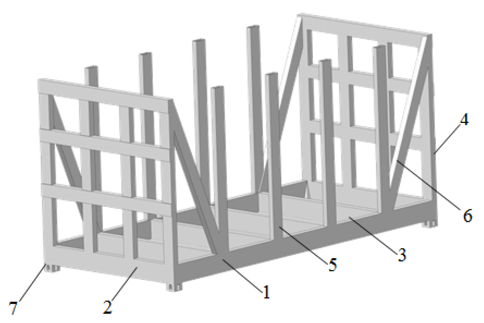
The peculiarity of the detachable module is its frame-based construction (
Figure 1). The loading platform is represented by a frame consisting of main longitudinal beams (1), main cross bearers (2), and a number of intermediate cross bearers (3). To prevent the load from moving in the longitudinal plane, the detachable module is equipped with end extensions (4). These extensions are formed by a combination of cross bearers and vertical beams.
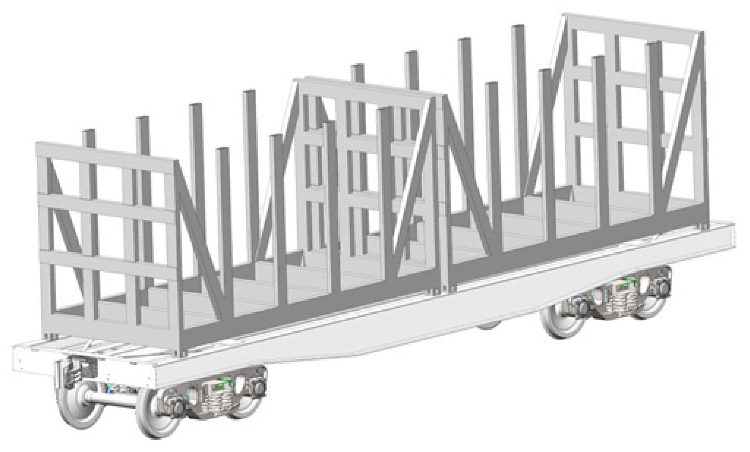
To prevent the load from moving laterally, the detachable module is equipped with side posts (5). In this case, the corner posts interact with the first post on the console side by inclined belts (6). Fitting stops (7) are provided in the corner parts of the detachable module for mounting it on vehicles. As an example,
Figure 2 shows the placement of a detachable module on a flat car, as one of the most common vehicles used for the transport of swap transport units in international traffic.
At the same time, the spatial stiffness of the vertical posts in the transverse direction will be ensured by the lashing devices used to keep the load from tipping over. One of these devices used on 1520 mm gauge railways is chains attached to the upper parts of posts located one opposite the other.
Loading the removable module with long cargo will be carried out from above with the help of handling and transport equipment, i.e., according to the existing technology of loading transport units of this type.
The detachable module profiles were chosen according to the moment of resistance using a known value of the maximum bending moments acting in its sections. The classical dependence of material resistance was used [
22,
23]:
where
M is the bending moment and [
σ] is the permissible stress.
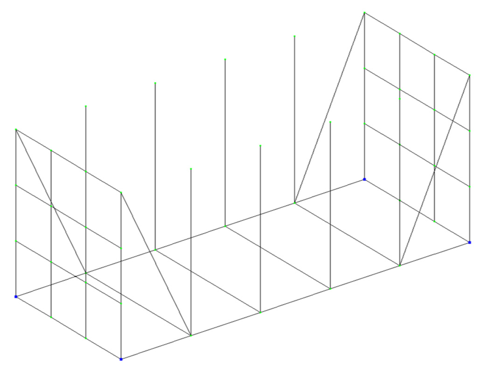
The detachable module was considered a rod system on four supports (
Figure 3). The calculation was made in LIRA–CAD [
24].
The geometric parameters of the detachable module are identical to those for 1CC containers. When creating the design diagram, the most unfavorable loading modes of the detachable module were taken into account: the perception of longitudinal loads (mode I) and lateral loads (mode II). Thus, the asymmetric load of the detachable module under operating conditions was taken into account.
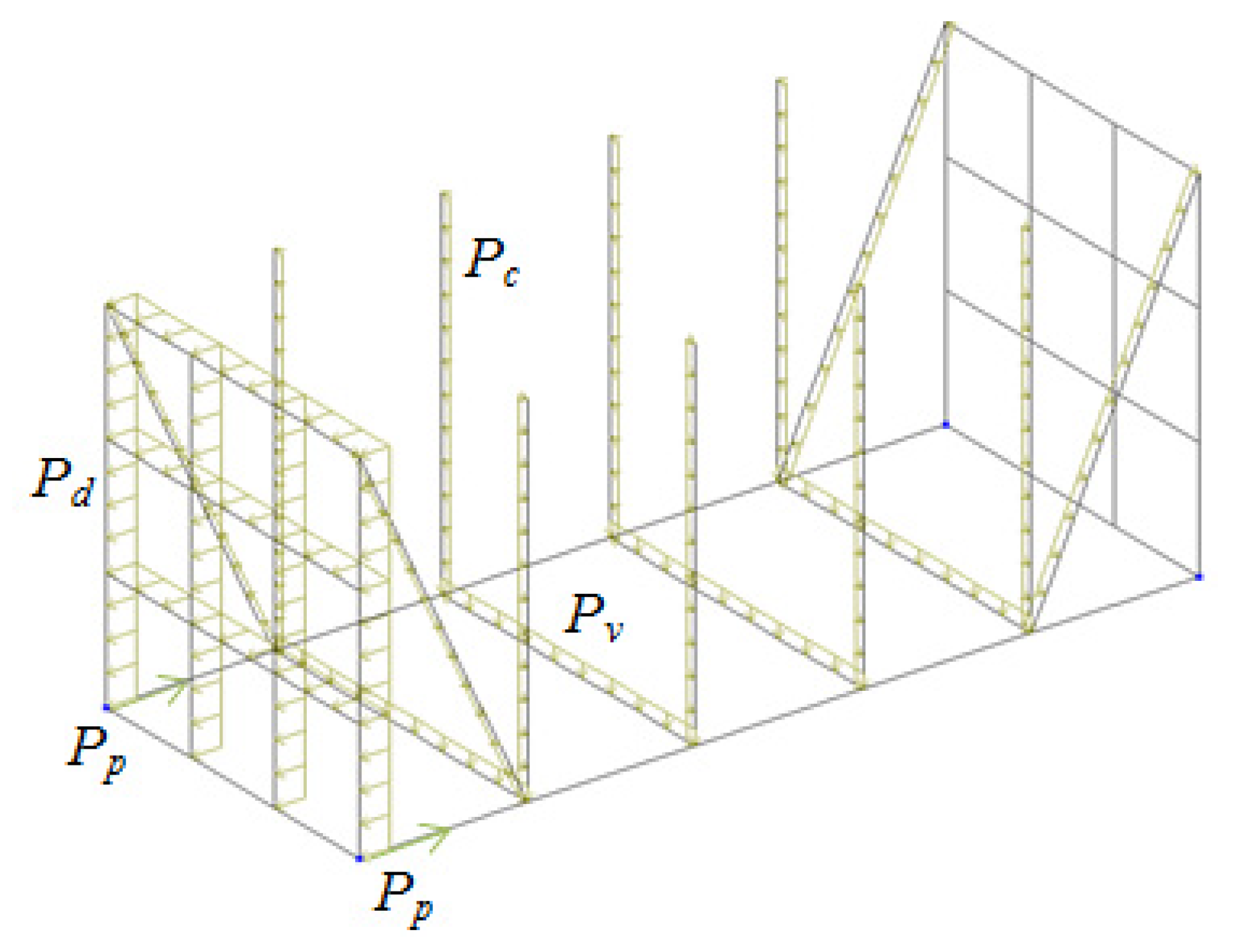
When drawing up the design diagram of the detachable module for mode I, the most unfavorable loading is taken into account, namely the shunting impact of the flat car [
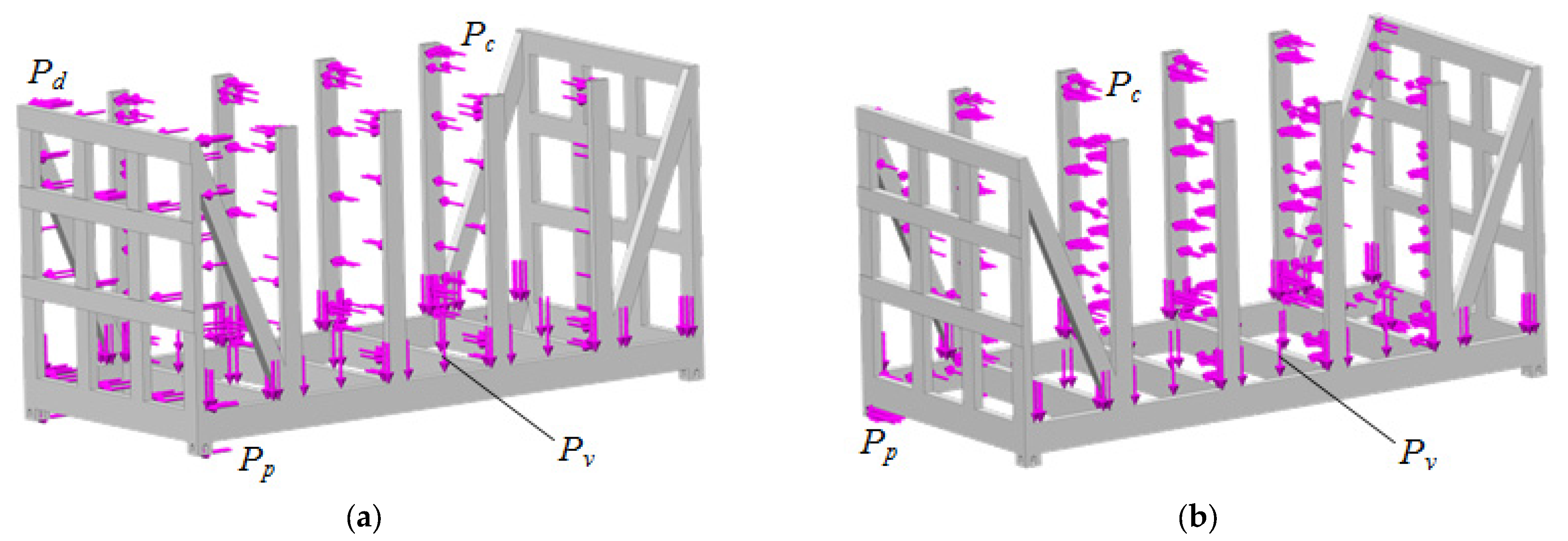
25]. The end support of the detachable module is subjected to a longitudinal load
Pd (
Figure 4). The vertical load
Pv is applied to the loading platform of the detachable module, caused by the dead weight of the detachable module and the freight placed on it. The side posts are subjected to the load
Pc caused by the pressure from the freight. The forces
Pp are applied to the fittings facing the engine.
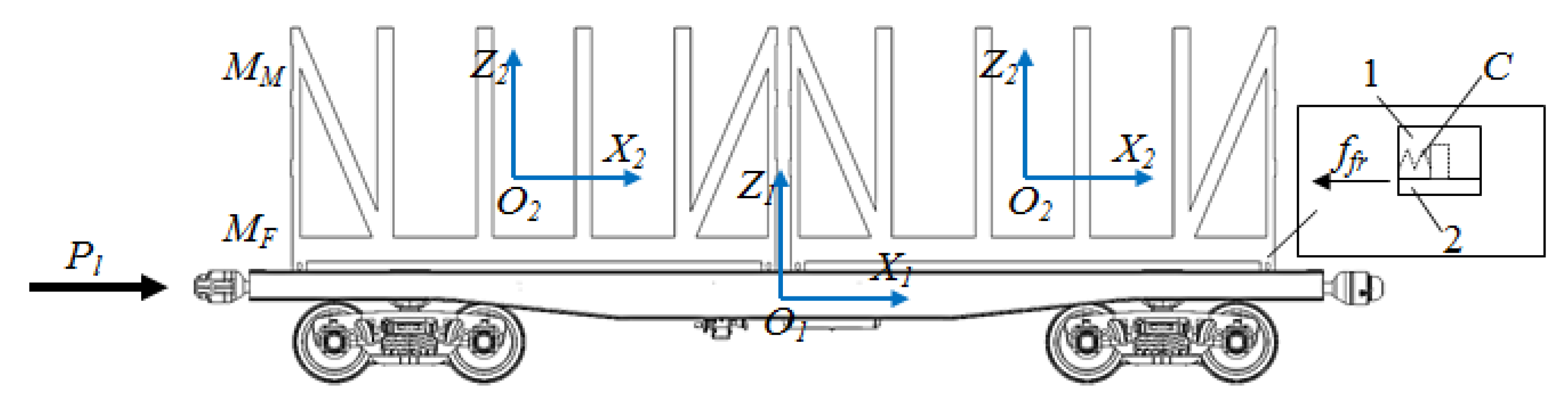
In order to determine the longitudinal load acting on the detachable module, mathematical modeling of its load is carried out. For this purpose, a mathematical model (1) is formed that characterizes the longitudinal load of the detachable module placed on the flat car. It is taken into account that a longitudinal force of 3.5 MN acts on the rear stop of the flat car [
25]. This force acts as an impulse.
Potential frictional forces that occur between the horizontal surfaces of the fitting stops of the flat car and the fittings of the detachable module are also taken into account [
26] (
Figure 5). The prototype is a 13–401 flat car with 18–100 bogies. It is important to note that this flat car is universal. However, due to the shortage of specialized wagons for container transport, this flat car has been modernized and equipped with fitting stops.
The modeling includes the rigid connection between the fitting stop and the container fitting.
The mathematical model has the following form:
where
MF is the gross weight of the flatcar;
Pl is the longitudinal force acting on the coupler; n is the number of detachable modules placed on the flatcar;
ffr is the frictional force between the fitting stops and fittings;
MM is the weight of the detachable module;
C is the rigidity of the connection between the fitting and the fitting stop; and
q1,
q2 are the coordinates that determine the displacement of the flatcar and the detachable module, respectively, relative to the longitudinal axis.
The mathematical model (1) is solved using the Runge–Kutta method [
27,
28,
29] in MathCad [
30,
31] under initial conditions close to zero [
32,
33,
34].
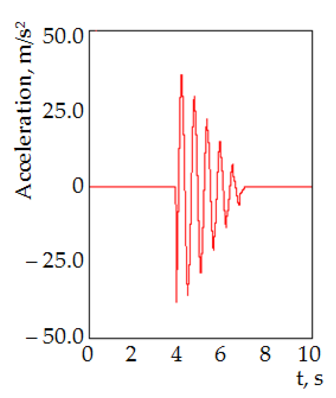
The generalized acceleration acting on the detachable module is determined in the array
ddqj,i [
35]:
where
It is found that the acceleration acting on the detachable module is about 37 m/s
2 (
Figure 6).
This acceleration value, as a component of the dynamic load, is taken into account when calculating the detachable module under mode I. According to the diagram (
Figure 4), the results of the calculation made it possible to obtain the distribution of internal factors in the detachable module components.
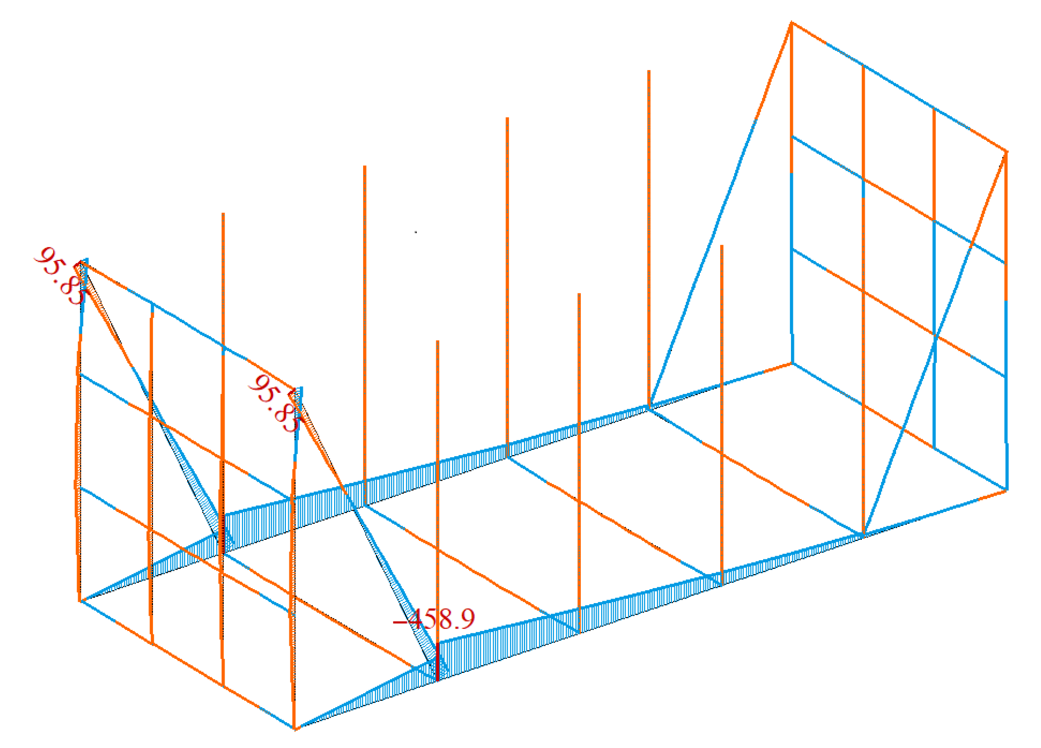
Figure 7 shows the bending moments (relative to the vertical axis) occurring in the detachable module. The negative value of the moments is in blue, and the positive one is in orange.
Therefore, the maximum values of the bending moments are in the areas of interaction between the inclined belts and the cross bearers; they are 458.9 kN·m.
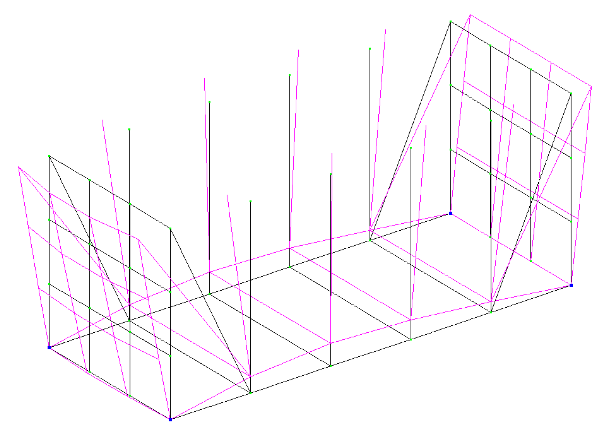
Using the software options in which the calculation was carried out, the diagram of displacements of the detachable module components under this design mode is also obtained (
Figure 8). In this case, the largest displacements occur at the end support placed on the side of the longitudinal load.
The next stage of this research included the determination of the bending moments in the detachable module in mode II. The design diagram of the detachable module is shown in
Figure 9.
It is taken into account that the vertical load Pv acts on the loading platform of the detachable module, and the load Pc is applied to the side posts. In this case, the load Pc, in addition to the pressure from the freight, also includes the load caused by the lateral inertia forces.
This load is determined by the following formula [
8]:
where
F′ is the transverse load caused by the centrifugal force;
W′ is the wind load; and
Lp is the post height.
The centrifugal force is determined according to the following formula [
25]:
where
Pgw is the gross weight of the detachable module;
V is the speed of the flat car with the detachable module; and
R is the curve radius.
Based on the calculations, the distribution of bending moments in the detachable module under lateral loads is obtained.
Figure 10 shows the bending moments (relative to the vertical axis) occurring in the detachable module.
The maximum values of bending moments are recorded in the areas of interaction between the side posts and the cross bearers; they amount to 10.91 kN·m.
The diagram of displacements of the detachable module components in design mode II is shown in
Figure 11.
The maximum displacements occur in the middle side posts on the tilt side of the detachable module.
Based on the calculated values of bending moments, the profiles of the detachable module were chosen. The most technologically rational profiles of the detachable module are taken into account, namely a structural channel and a rectangular pipe (
Figure 12) [
36,
37].
For example, for a loading platform with a calculated value of the resistance moment W = 277.8 cm
3, it is rational to use the specified profiles with the parameters given in
Table 1.
Therefore, it is more appropriate to use the channel profile of the detachable module. It is important to note that this profile is one of the most common used for modular vehicles.
To increase the moment of resistance of the section, it can be reinforced with a vertical sheet (
Figure 13). This decision is justified by the fact that vehicles, in particular, for railway use, must have a structural safety margin. The minimum safety factor in accordance with [
25] should be 1.3. To ensure an adequate safety margin, it is necessary to use a sheet with a thickness of 4 mm. In this case, the moment of resistance of the cross-section is 360 cm
3 with a weight of 1 m—35.6 kg.
The parameters of the profiles for the end superstructures and vertical posts were chosen in the same way: channel No. 20, reinforced with sheet metal, 3.5 mm thick.
3. Results
Taking into account the selected profiles of the detachable module frame, its spatial model was created, and the strength calculation was performed in SolidWorks Simulation [
38,
39,
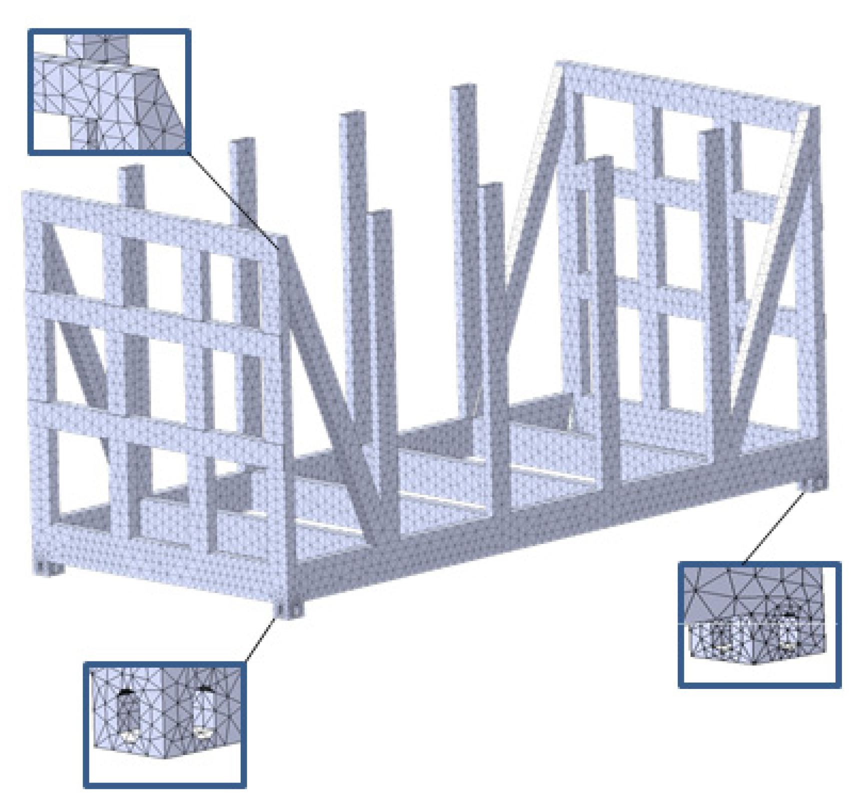
40]. The finite element model (
Figure 14) was formed by a spatial tetrahedral [
40,
41]. This element type was chosen due to the fact that the mesh was formed on a solid body. The optimal number of grid elements is determined by the graphoanalytical method. The method is based on a graphical (geometric) representation of admissible solutions and the objective function of the problem. The essence of the method for solving this problem is to construct the dependence of the maximum equivalent stresses on the number of finite elements. When this dependence begins to be described by a horizontal line, this is the optimum number of finite elements. Taking this into account, the model has 150,474 elements with a maximum size of 100 mm and a minimum size of 20 mm, as well as 55,221 nodes. When creating the mesh, it is automatically compacted in the areas of rounding and conjugating individual elements.
The design diagrams of the detachable module are shown in
Figure 15. In these diagrams, the designation of the forces is identical to those shown in
Figure 4 and
Figure 9, respectively.
Connections are applied to the fitting stops of the detachable module to simulate its interaction with the fitting stops of the flat car. The construction material of the detachable module is low-alloy steel 09G2S. This steel grade is one of the most commonly used in the car building industry for the construction of vehicles [
25]. When conducting calculations, welding seams between individual components of the removable module were not taken into account, i.e., the design was considered monolitic.
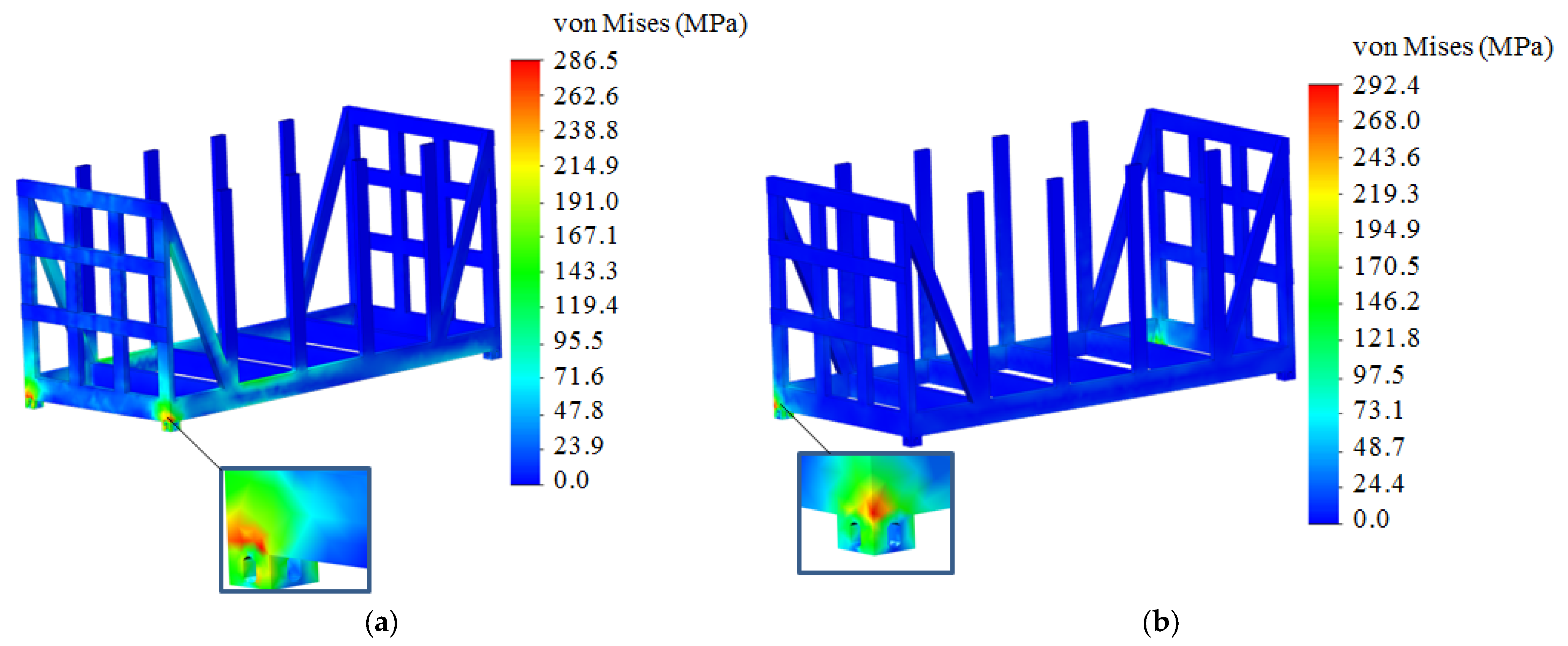
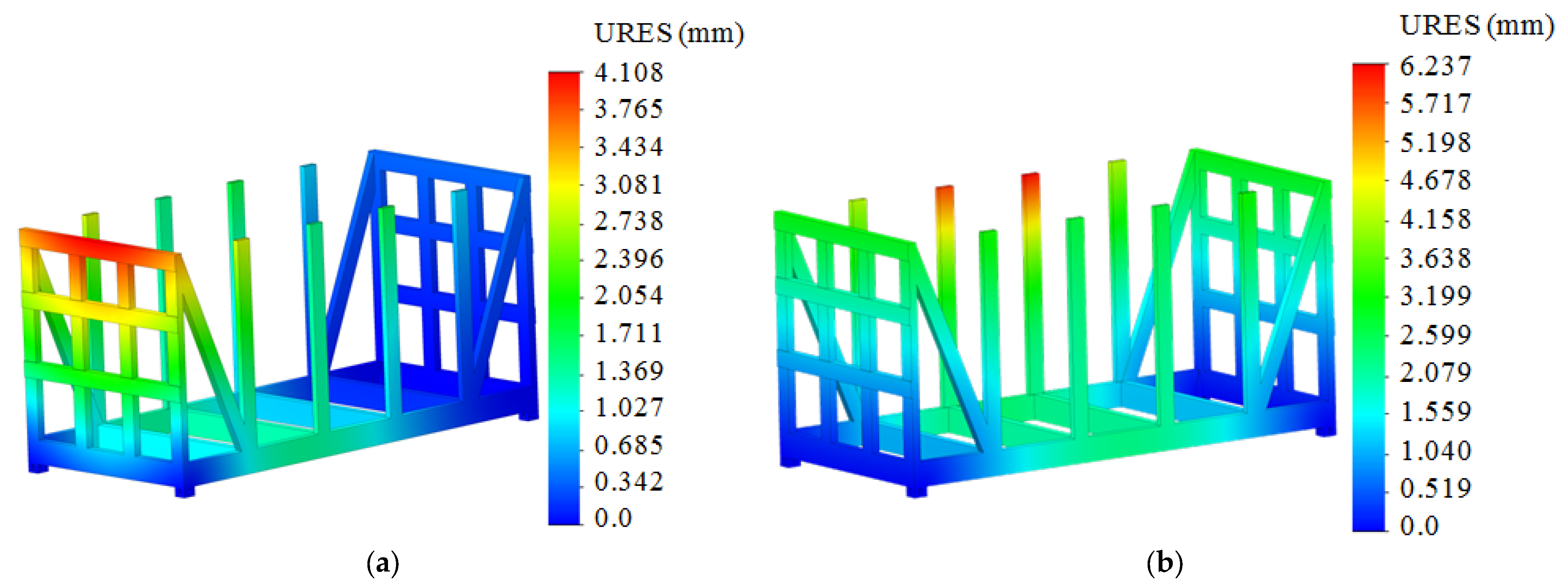
The results of the calculation of the detachable module are shown in
Figure 16 and
Figure 17. Analyzing the results, it can be concluded that the maximum stresses in the structure of the detachable module at mode I occur in the cross bearers in the areas of their interaction with the fittings; they amount to 286.5 MPa (
Figure 16a). The resulting stresses are lower than permissible by 7.7%. The stresses equal to 310.5 MPa are taken as permissible [
25]. These stresses are accepted as permissible, since at mode I, the permissible stresses in accordance with the regulatory document [
25] are taken as equal to 0.9σ
y, where σ
y is the yield strength of the material. For steel grade 09G2S, it is 345 MPa.
The maximum displacements in the detachable module structure at mode I occur in the upper belt of the end superstructure and amount to 4.1 mm (
Figure 17a). This distribution of displacement fields is explained by the fact that the superstructure interacts with the detachable module components on all sides, and its upper part is free.
At mode II, the maximum displacements are recorded in the central posts on the tilt side of the detachable module. These displacements are 6.2 mm (
Figure 17b). Their presence can be explained by the fact that the vertical post is fixed at the bottom while its upper end is free.
At mode II, the maximum stresses are recorded in the main longitudinal beam on the tilt side of the detachable module and amount to 292.4 MPa (
Figure 16b). These stresses are concentrated in the areas of interaction between the main longitudinal beam and the fitting stops. However, they do not exceed the permissible ones and are 5.8% lower.
It should be noted that the obtained displacement fields are consistent with the diagrams shown in
Figure 8 and
Figure 11.
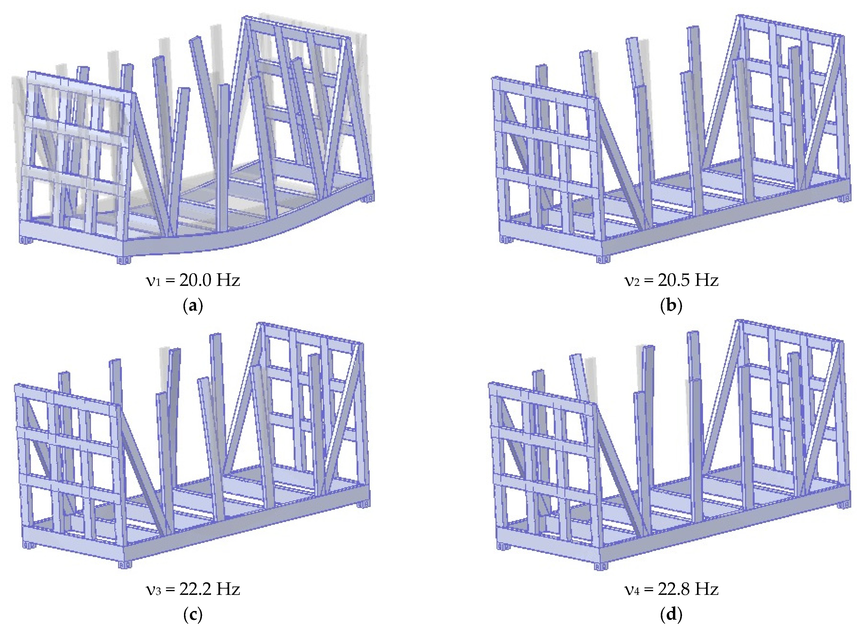
To ensure safe operation of the detachable module, its modal analysis was carried out. This was performed using the built-in options in SolidWorks Simulation (version 2015). The purpose of this calculation was to determine the natural frequencies and forms of oscillations of the removable module. The results of the calculation are shown in
Figure 18.
In
Figure 18, the transparent color indicates the static form of the detachable module, and the matte color indicates the deformed shape. For better visualization, the scale of deformations is increased by a factor of 15.
Traffic safety is assessed by the first oscillation frequency, which, in accordance with [
25], should be at least 8 Hz. Therefore, it can be concluded that, according to the modal analysis, traffic safety is ensured.
It is important to note that the analog of the regulatory document [
25] is the European standard [
42]. However, it regulates the specifics of the loading of wagons of the 1435 mm gauge, and it has certain differences from the standard [
25]. In connection with the fact that the calculation was carried out on the example of the transport of the removable module by a platform car with a gauge of 1520 mm, at this stage of this study, the authors limited themselves to the requirements specified in the standard [
25]. In the subsequent stages of research, the requirements regulated by the standard [
42] will be taken into account.
4. Discussion
To improve the efficiency of the transportation process, the design of a detachable module for the transportation of long cargoes is proposed (
Figure 1). The choice of profiles for the detachable module is based on the resistance moments of its components. For this purpose, the relevant calculations are carried out in LIRA-CAD. In this case, the detachable module is considered a rod system (
Figure 3). Mathematical modeling is carried out to determine the longitudinal loads acting on the detachable module in operation when it is placed on a flat car. The most unfavorable loading condition of the flat car, i.e., the shunting impact, is taken into account. In accordance with regulatory document [
25], a longitudinal force of 3.5 MN is applied to the rear stop of the coupler. The calculations show that the maximum acceleration acting on the flat car loaded with two detachable modules is about 37 m/s
2 (
Figure 6). This acceleration value, as a component of the dynamic load, is taken into account in further calculations of the detachable module. Based on the calculations, a structural channel reinforced with a vertical sheet is chosen as the profile of the detachable module (
Figure 13). This decision is justified by the fact that the minimum safety factor in accordance with [
25] should be 1.3. Therefore, to ensure an adequate safety margin, it is proposed to reinforce the structural channel with a 5-mm vertical sheet.
The strength calculation of the detachable module under asymmetric loading diagrams in operation (perception of longitudinal loads—mode I, and lateral loads—mode II) is carried out. It is found that the maximum stresses in the detachable module structure at mode I are 286.5 MPa (
Figure 16a). These stresses are 7.7% lower than the permissible values.
The maximum displacements in the structure of the detachable module occur in the upper belt of the end superstructure and amount to 4.1 mm (
Figure 17a).
The maximum stresses at mode II are 292.4 MPa (
Figure 16b). It is important to note that these stresses do not exceed the permissible ones and are 5.8% lower. The maximum displacements are recorded in the central posts on the tilt side of the detachable module and amount to 6.2 mm (
Figure 17b).
This study also includes a modal analysis of the detachable module. Traffic safety is assessed by the first natural oscillation frequency, which, in accordance with [
25], should be at least 8 Hz. The calculations show that the first natural frequency of oscillation is 20 Hz. Thus, traffic safety is ensured from the point of view of modal analysis.
The limitation of this study is that the mathematical modeling of the longitudinal load of the detachable module includes a rigid fixation of the freight (zero degrees of freedom).
The disadvantage of this study is that it includes only two loading diagrams of the detachable module. However, this disadvantage can be justified by the fact that the modes in question are the most unfavorable regarding the detachable module load.
The advantage of this study in comparison with [
8] is that the proposed design of the detachable module does not require a special maintenance and repair system and can be carried out at rail enterprises using the existing technologies. In contrast to the vehicle designs proposed in [
9,
11], the detachable module can be used to transport a variety of freight, apart from long cargoes.
Compared to the results of [
10,
12,
13,
14], the proposed detachable module design is mobile, which increases the efficiency of its operation in contrast to flat cars.
The disadvantage of the solutions proposed in [
15,
16] is that they require situational adaptation of the existing wagon fleet for the transportation of long cargoes. Moreover, the introduction of detachable modules is more efficient, especially for international transportation.
In comparison with publications [
17,
18,
19,
20,
21], the advantage of this detachable module is that it can be used not only for the transportation of long cargoes but also for other types of freight, which will increase their demand.
The scientific value of this study is the proposed procedure for creating a removable module for transporting long loads, which includes the selection of profiles for its implementation according to the moment of resistance of the structural components, the determination of dynamic load, strength, and natural frequencies and forms of oscillations. At the same time, it should be emphasized that the determination of the dynamic load of the removable module was carried out according to the mathematical model formed by the authors of this study and verified in their previous works.
Patent applications have been submitted for the proposed design of the removable module.
A further development of this study may include the investigation of the dynamic load and strength of the detachable module under other operating loading modes when transported by other vehicles.
5. Conclusions
1. The design of the detachable module for the transportation of long cargoes is proposed. The peculiarity of the detachable module is its frame-based construction. The loading platform is the frame. The profiles of the detachable module are determined based on the resistance moments of its components.
Mathematical modeling is carried out to determine the dynamic load of the detachable module. It is found that the maximum acceleration acting on a flat car with two detachable modules is about 37 m/s2. The resulting acceleration is taken into account in further calculations for the detachable module. Channel No. 27, reinforced with a vertical sheet, 4 mm thick, is chosen as the frame profile; channel No. 20, reinforced with a sheet, 3.5 mm thick, is chosen for the end superstructures and vertical posts.
2. The strength of the detachable module under longitudinal loads is calculated. The maximum stresses in the structure of the detachable module amount to 286.5 MPa and occur in the cross bearers in the areas of their interaction with the fittings. These stresses are 7.7% lower than permissible ones. The maximum displacements in the structure of the detachable module occur in the upper belt of the end superstructure and are 4.1 mm.
3. The strength of the detachable module under lateral loads is calculated. The maximum stresses in the structure of the detachable module are 292.4 MPa. These stresses are concentrated in the areas of interaction between the main longitudinal beam and the fitting stops. They do not exceed the permissible stresses and are 5.8% lower. The maximum displacements are recorded in the central posts on the tilt side of the detachable module and amount to 6.2 mm.
This research also includes a modal analysis and the determination of the natural frequencies and oscillation shapes of the detachable module. The first natural oscillation frequency of the detachable module is found to be 20 Hz. Thus, according to the frequency analysis, the safety of the detachable module is ensured.
This research will help to create recommendations for the design of modern modular vehicles and improve the efficiency of the transport industry.


