
Beamforming for the Successive Relaying-Based Cooperative Non-Orthogonal Multiple Access Transmission

Abstract
:1. Introduction
1.1. Related Works
1.2. Contribution
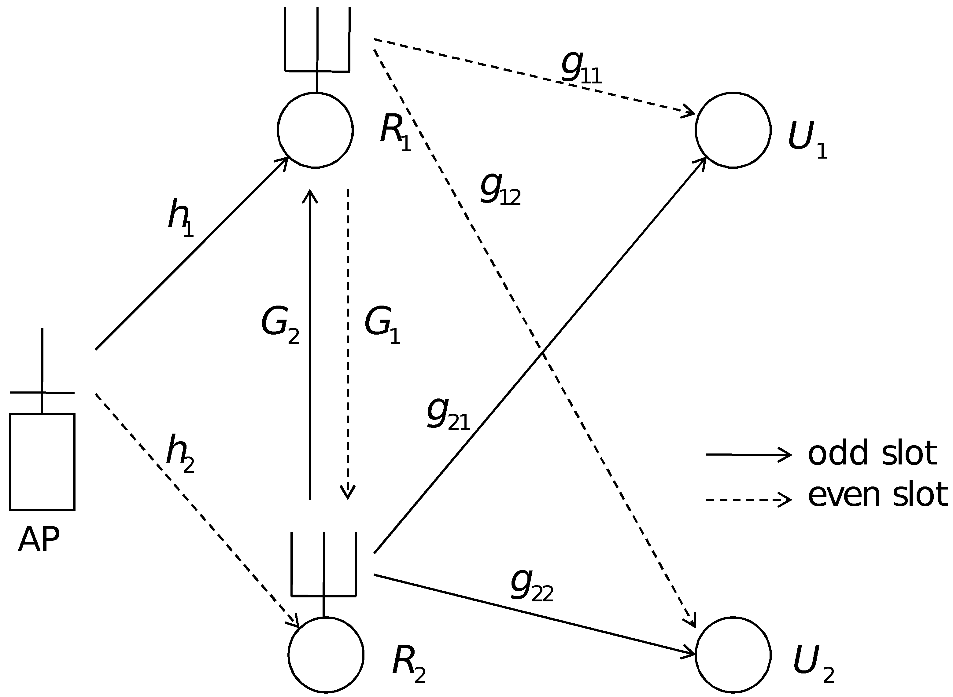
2. System Model
3. Beamformer Design
3.1. Multi-Dimensional Search Design with CRI Zero Forcing
| Algorithm 1: The twin iterative 2-D search algorithms for the SR-CNOMA |
| 1. for do |
| 2. Set , and . |
| 3. Set . |
| 4. end for |
| 5. while ( and for do not reduce more than a set of marginal values) do |
| 6. for do |
| 7. Set and . |
| 8. end for |
| 9. Perform the optimizations in (7) and (8). |
| 10. for do |
| 11. if () then |
| 12. Set and . |
| 13. else |
| 14. Set and . |
| 15. end if |
| 16. end for |
| 17. for do |
| 18. Set . |
| 19. end for |
| 20. end while |
| 21. for do |
| 22. Set and . |
| 23. end for |
| 24. Perform the optimizations in (7) and (8). |
| 25. for do |
| 26. Set . |
| 27. Scale such that . |
| 28. Calculate and using (3) and (6). |
| 29. end for |
| 30. Calculate using (5). |
3.2. One-Shot Design with CRI Zero Forcing
| Algorithm 2: The one-shot algorithm |
| 1. for do |
| 2. Set . |
| 3. Set . |
| 4. Scale such that . |
| 5. Calculate and using (3) and (4). |
| 6. end for |
| 7. Calculate using (5). |
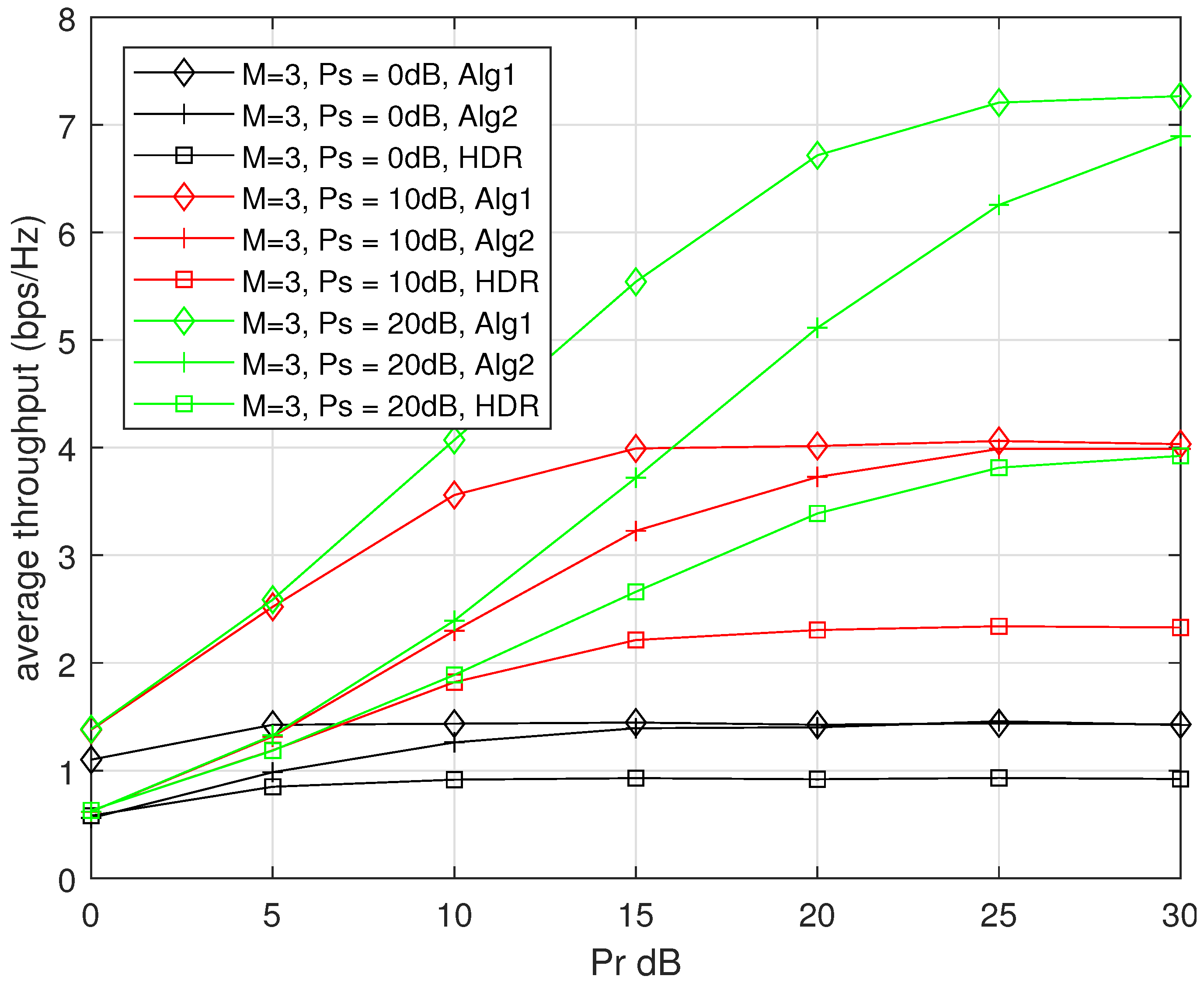
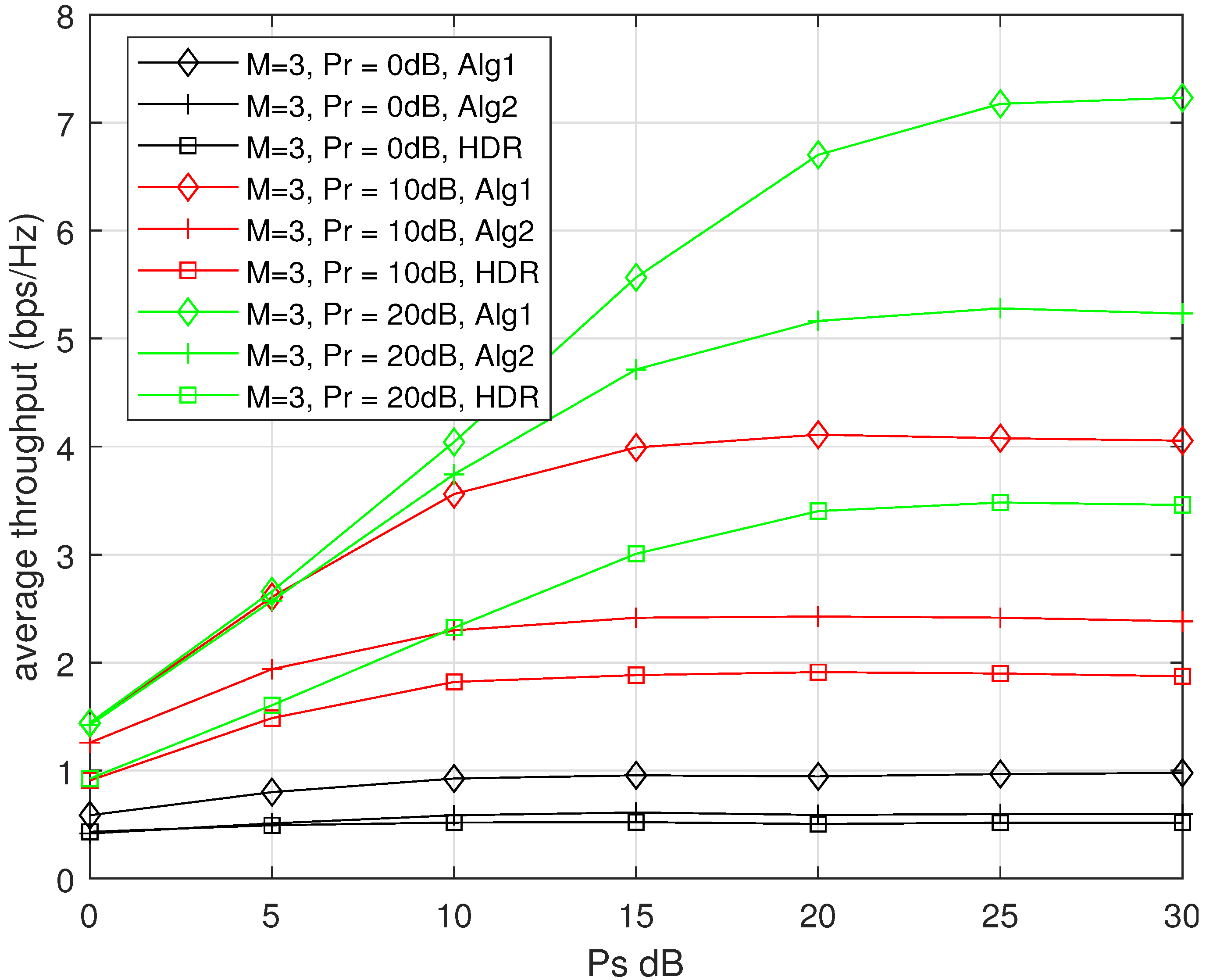
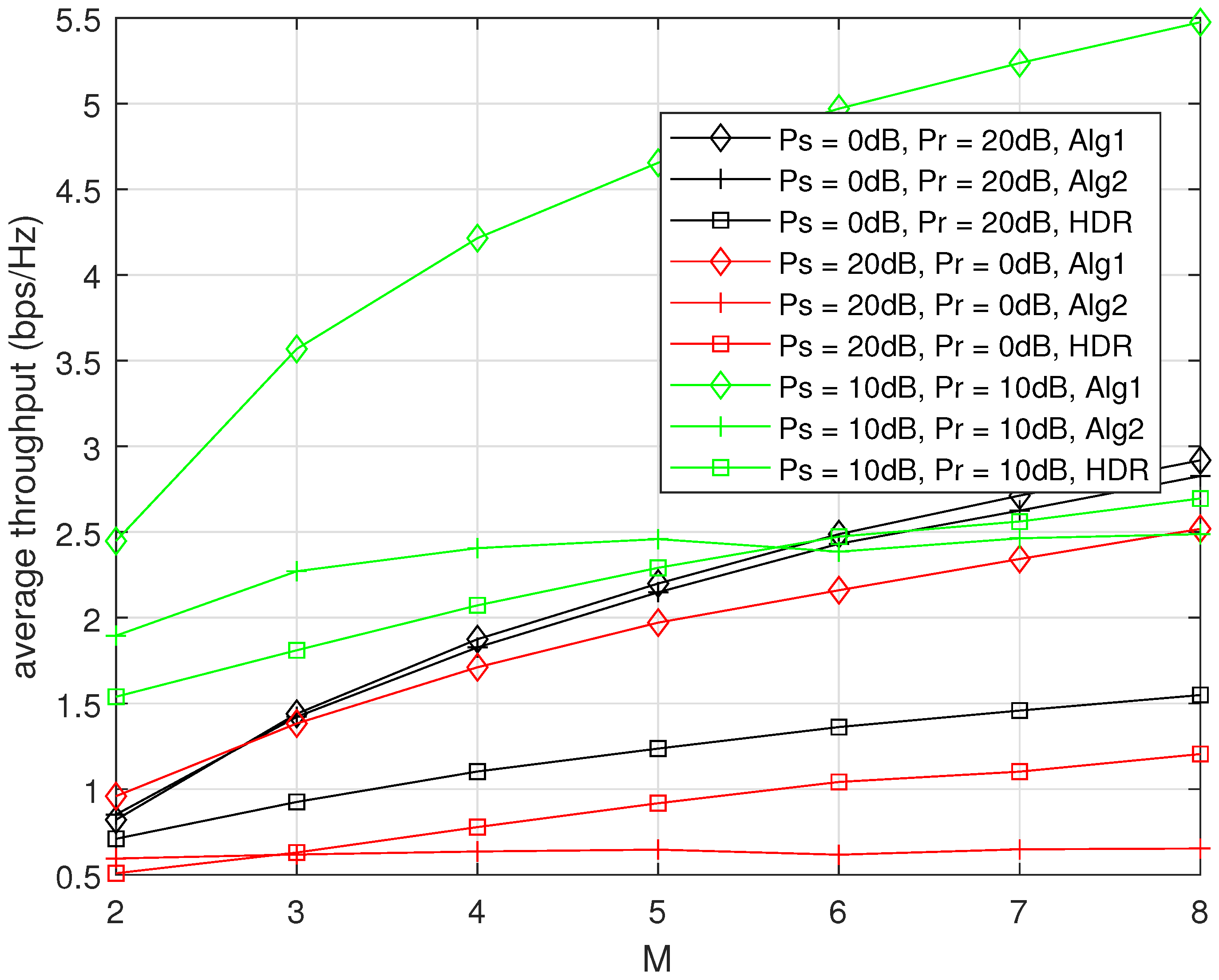
4. Numerical Results
5. Conclusions
Author Contributions
Funding
Data Availability Statement
Conflicts of Interest
References
- Saito, Y.; Kishyama, Y.; Benjebbour, A.; Nakamura, T.; Li, A.; Higuchi, K. Non-Orthogonal Multiple Access (NOMA) for Cellular Future Radio Access. In Proceedings of the 2013 IEEE 77th Vehicular Technology Conference (VTC Spring), Dresden, Germany, 2–5 June 2013; pp. 1–5. [Google Scholar]
- Wang, Q.; Zhang, R.; Yang, L.-L.; Hanzo, L. Non Orthogonal Multiple Access: A Unified Perspective. IEEE Wirel. Commun. Mag. 2018, 25, 10–16. [Google Scholar] [CrossRef]
- Liu, Y.; Pan, C.; Nallanathan, A.; Elkashan, M.; Hanzo, L. Multiple-Antenna-Assisted Non-Orthogonal Multiple Access. IEEE Wirel. Commun. Mag. 2018, 25, 17–23. [Google Scholar] [CrossRef]
- Huang, Y.; Zhang, C.; Wang, J.; Jing, Y.; Yang, L.; You, Z. Signal Processing for MIMO-NOMA: Present and Future Challenges. IEEE Wirel. Commun. Mag. 2018, 25, 32–38. [Google Scholar] [CrossRef]
- Fang, F.; Zhang, H.; Cheng, J.; Leung, V.C.M. Energy-Efficient Resource Allocation for Downlink Non-Orthogonal Multiple Access Network. IEEE Trans. Commun. 2016, 64, 3722–3732. [Google Scholar] [CrossRef]
- Bao, W.; Chen, H.; Li, Y.; Vucetic, B. Joint Rate Control and Power Allocation for Non-Orthogonal Multiple Access Systems. IEEE J. Sel. Areas Commun. 2017, 35, 2798–2811. [Google Scholar] [CrossRef]
- Zhu, J.; Wang, J.; Huang, Y.; He, S.; You, X.; Yang, L. On Optimal Power Allocation for Downlink Non-Orthogonal Multiple Access Systems. IEEE J. Sel. Areas Commun. 2017, 35, 2744–2757. [Google Scholar] [CrossRef]
- Pliatsios, D.; Sarigiannidis, P. Resource allocation combining heuristic matching and particle swarm optimization approaches: The case of downlink non-orthogonal multiple access. Information 2019, 10, 336. [Google Scholar] [CrossRef]
- Zhao, C.; Cai, Y.; Liu, A.; Zhao, M.; Hanzo, L. Mobile edge computing meets mmWave communications: Joint beamforming and resource allocation for system delay minimization. IEEE Trans. Wirel. Commun. 2020, 19, 2382–2396. [Google Scholar] [CrossRef]
- Zhu, Z.X.L.; Choi, J.; Xia, P.; Xia, X. Joint power allocation and beamforming for non-orthogonal multiple access (NOMA) in 5G millimeter wave communications. IEEE Trans. Wirel. Commun. 2018, 17, 2961–2974. [Google Scholar] [CrossRef]
- Zhu, L.; Zhang, J.; Xiao, Z.; Cao, X.; Wu, D.; Xia, X. Millimeter-wave NOMA with user grouping, power allocation and hybrid beamforming. IEEE Trans. Wirel. Commun. 2019, 18, 5065–5079. [Google Scholar] [CrossRef]
- Hanif, M.F.; Ding, Z.; Ratnarajah, T.; Karagiannidis, G.K. A Minorization-Maximization Method for Optimizing Sum rate in the Downlink of Non-Orthogonal Multiple Access Systems. IEEE Trans. Veh. Technol. 2016, 64, 76–88. [Google Scholar] [CrossRef]
- Ding, Z.; Adachi, F.; Poor, H.V. The Application of MIMO to Non-Orthogonal Multiple Access. IEEE Trans. Wirel. Commun. 2016, 15, 537–552. [Google Scholar] [CrossRef]
- Ding, Z.; Schober, R.; Poor, H.V. A General MIMO framework for NOMA downlink and uplink transmission based on signal alignment. IEEE Trans. Wirel. Commun. 2016, 15, 4438–4454. [Google Scholar] [CrossRef]
- Chen, Z.Y.; Ding, Z.; Dai, X. Beamforming for Combating Inter-cluster and Intra-cluster Interference in Hybrid NOMA Systems. IEEE Access 2016, 4, 4452–4463. [Google Scholar] [CrossRef]
- Jeong, Y.; Lee, C.; Kim, Y. Power minimizing beamforming and power allocation for MISO-NOMA systems. IEEE Trans. Veh. Technol. 2019, 68, 6187–6191. [Google Scholar] [CrossRef]
- Sun, X.; Nan, Y.; Yan, S.; Ding, Z.; Ng, D.; Shen, C.; Zhong, Z. Joint beamforming and power allocation in downlink NOMA multiuser MIMO networks. IEEE Trans. Wirel. Commun. 2018, 17, 5367–5381. [Google Scholar] [CrossRef]
- Al-Obiedollah, H.; Cumanan, K.; Thiyagalingam, J.; Burr, A.G.; Ding, Z.; Dobre, O.A. Energy efficient beamforming design for MISO non-orthogonal multiple access systems. IEEE Trans. Commun. 2019, 67, 4117–4131. [Google Scholar] [CrossRef]
- Alavi, F.; Cumanan, K.; Ding, Z.; Burr, A.G. Beamforming techniques for nonorthogonal multiple access in 5G cellular networks. IEEE Trans. Veh. Technol. 2018, 67, 9474–9487. [Google Scholar] [CrossRef]
- Nandan, N.; Sudhan, M.; Wu, H. Secure beamforming for MIMO-NOMA-based cognitive radio network. IEEE Commun. Lett. 2018, 8, 1708–1711. [Google Scholar] [CrossRef]
- Feng, Y.; Yan, S.; Yang, Z.; Yang, N.; Yuan, J. Beamforming Design and Power Allocation for Secure Transmission with NOMA. IEEE Trans. Wirel. Commun. 2019, 18, 2639–2651. [Google Scholar] [CrossRef]
- Xu, Y.; Shen, C.; Ding, Z.; Sun, X.; Yan, S.; Zhu, G.; Zhong, Z. Joim Beamforming and Power-Spliting Control in Downlink Cooperative SWIPT NOMA Systems. IEEE Trans. Signal Process. 2017, 65, 4874–4886. [Google Scholar] [CrossRef]
- Alsaba, Y.; Leow, C.Y.; Rahim, S.K.A. Full-Duplex Cooperative Non-orthogonal multiple access with beamforming and energy harvesting. IEEE Access 2018, 6, 19726–19738. [Google Scholar] [CrossRef]
- Zhang, Z.; Ma, Z.; Xiao, M.; Ding, Z.; Fan, P. Full-Duplex Device-to-device-aided Cooperative Non-orthogonal multiple access. IEEE Trans. Veh. Technol. 2017, 66, 4467–4471. [Google Scholar] [CrossRef]
- Kim, J.; Lee, I. Capacity Analysis of Cooperative relaying Systems Using Non-Orthogonal Multiple Access. IEEE Commun. Lett. 2015, 19, 1949–1952. [Google Scholar] [CrossRef]
- Ding, Z.; Peng, M.; Poor, H.V. Cooperative Non-Orthogonal Multiple Access in 5G Systems. IEEE Commun. Lett. 2015, 19, 1462–1465. [Google Scholar] [CrossRef]
- Yang, Z.; Ding, Z.; Wu, Y.; Fan, P. Novel Relay Selection Strategies for Cooperative NOMA. IEEE Trans. Veh. Technol. 2017, 66, 10114–10123. [Google Scholar] [CrossRef]
- Liau, Q.Y.; Leow, C.Y.; Ding, Z. Amplify-and-Forward Virtual Full-Duplex Relaying-Based Cooperative NOMA. IEEE Wirel. Commun. Lett. 2018, 7, 464–467. [Google Scholar] [CrossRef]
- Hwang, D.; Yang, J.; Nam, S.S.; Jeong, J.; Song, H. Cooperative Non-Orthogonal Multiple Access Transmission through Full-Duplex and Half-Duplex Relays. IEEE Wirel. Commun. Lett. 2023, 12, 351–355. [Google Scholar] [CrossRef]
- Sidiropoulos, N.D.; Davidson, T.N.; Luo, Z.Q. Transmit Beamforming for Physical-Layer Multicasting. IEEE Trans. Signal Process. 2006, 54, 2239–2251. [Google Scholar] [CrossRef]


Disclaimer/Publisher’s Note: The statements, opinions and data contained in all publications are solely those of the individual author(s) and contributor(s) and not of MDPI and/or the editor(s). MDPI and/or the editor(s) disclaim responsibility for any injury to people or property resulting from any ideas, methods, instructions or products referred to in the content. |
© 2024 by the authors. Licensee MDPI, Basel, Switzerland. This article is an open access article distributed under the terms and conditions of the Creative Commons Attribution (CC BY) license (https://creativecommons.org/licenses/by/4.0/).
Share and Cite
Hwang, D.; Nam, S.S.; Yang, J.; Song, H.-K. Beamforming for the Successive Relaying-Based Cooperative Non-Orthogonal Multiple Access Transmission. Appl. Sci. 2024, 14, 3246. https://doi.org/10.3390/app14083246
Hwang D, Nam SS, Yang J, Song H-K. Beamforming for the Successive Relaying-Based Cooperative Non-Orthogonal Multiple Access Transmission. Applied Sciences. 2024; 14(8):3246. https://doi.org/10.3390/app14083246
Chicago/Turabian StyleHwang, Duckdong, Sung Sik Nam, Janghoon Yang, and Hyoung-Kyu Song. 2024. "Beamforming for the Successive Relaying-Based Cooperative Non-Orthogonal Multiple Access Transmission" Applied Sciences 14, no. 8: 3246. https://doi.org/10.3390/app14083246