
Metal Artifact Correction in Industrial CT Images Based on a Dual-Domain Joint Deep Learning Framework


Abstract
1. Introduction
- -
- Beam Hardening: The nonlinear effects caused by varying attenuation characteristics of different materials are often not apparent in the projection domain.
- -
- Scattering: Some scattering effects may be more readily identified and corrected in the image domain.
- -
- Statistical Noise: The randomness of noise means that noise reduction within the projection domain might not cater to variations in local image characteristics.
- -
- Reconstruction Algorithm Shortcomings [15]: For example, the filters used in filtered back projection (FBP) may not entirely eliminate streaks caused by metal.
2. Method
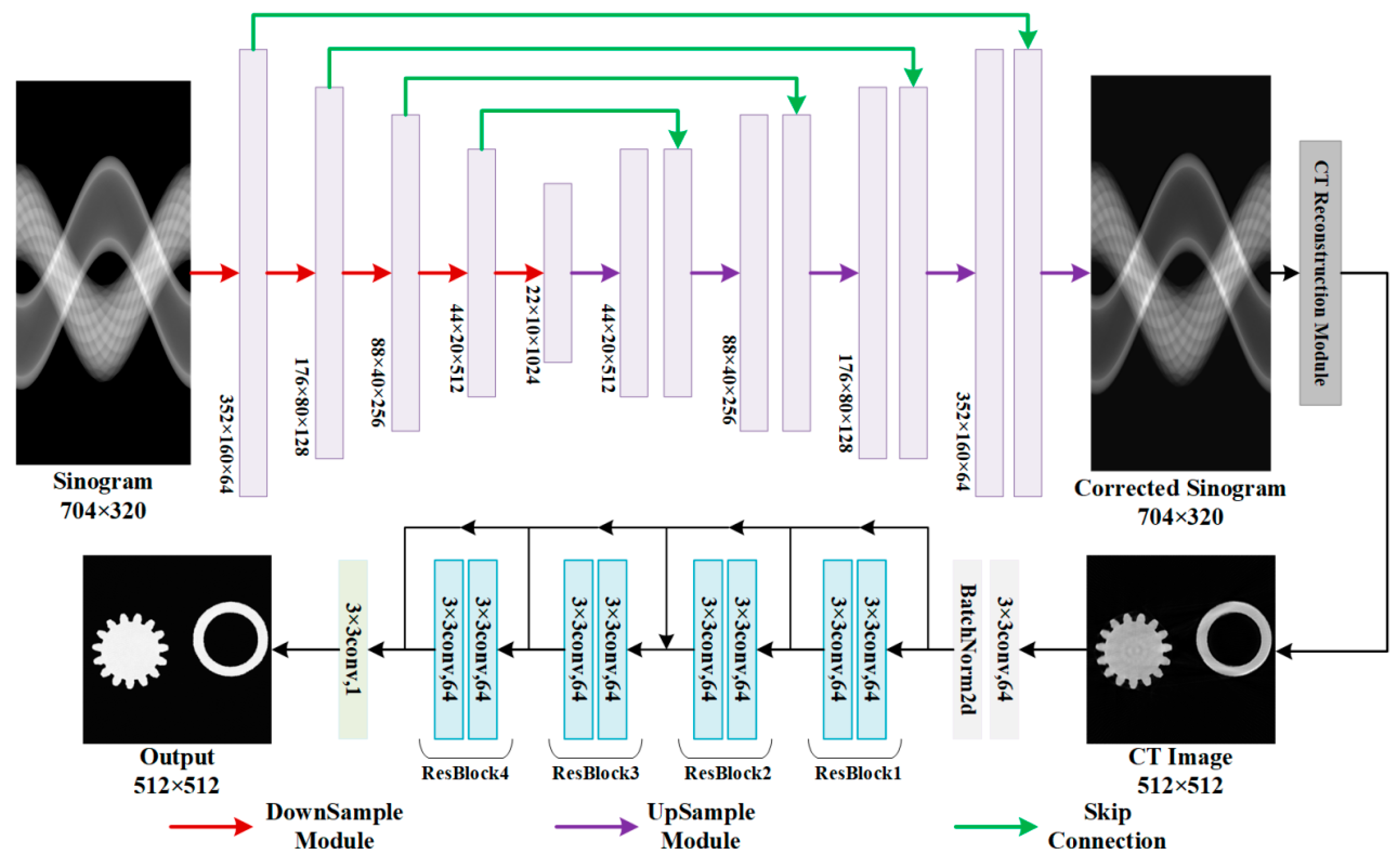
2.1. Overview of the Dual-Domain Joint Deep Learning Framework
2.2. UNet Network for Projection Domain Correction
2.3. ResNet Network for Image Domain Correction
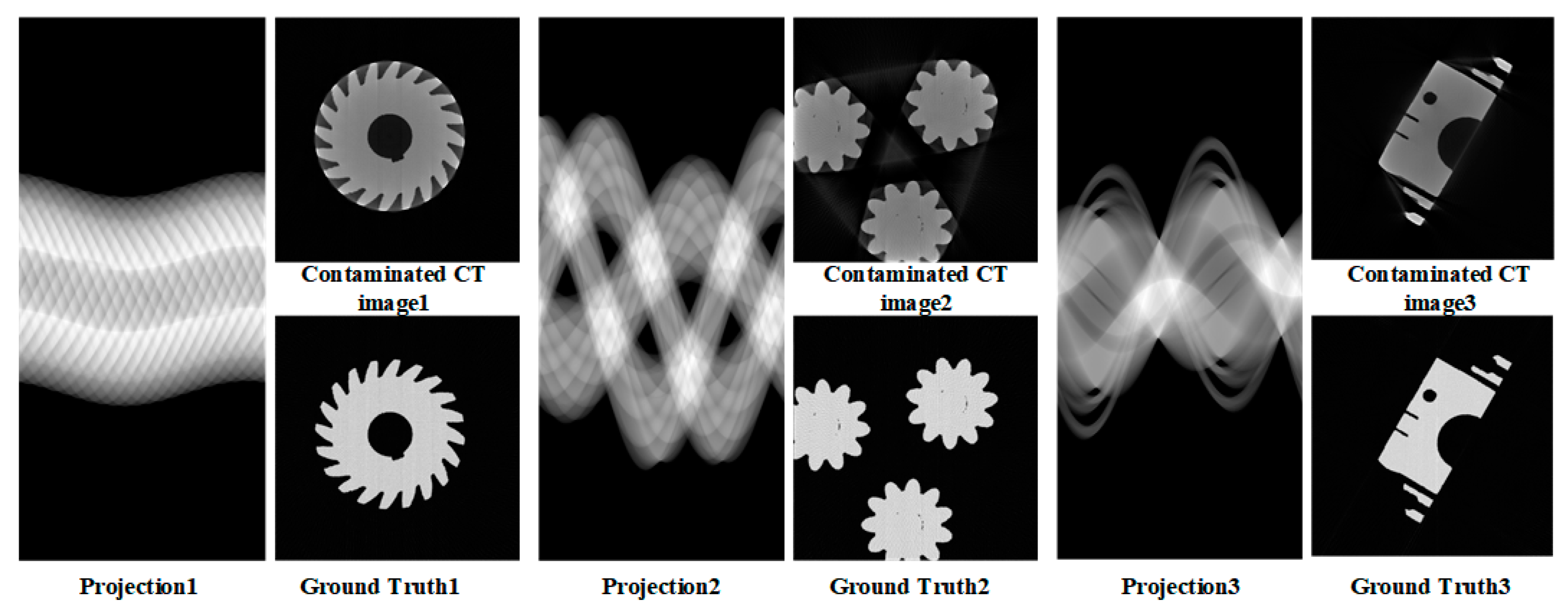
2.4. Dataset Acquisition
2.5. Joint Training Process
3. Experiment and Results
3.1. Experiment
3.1.1. Training Details
3.1.2. Evaluation Metrics
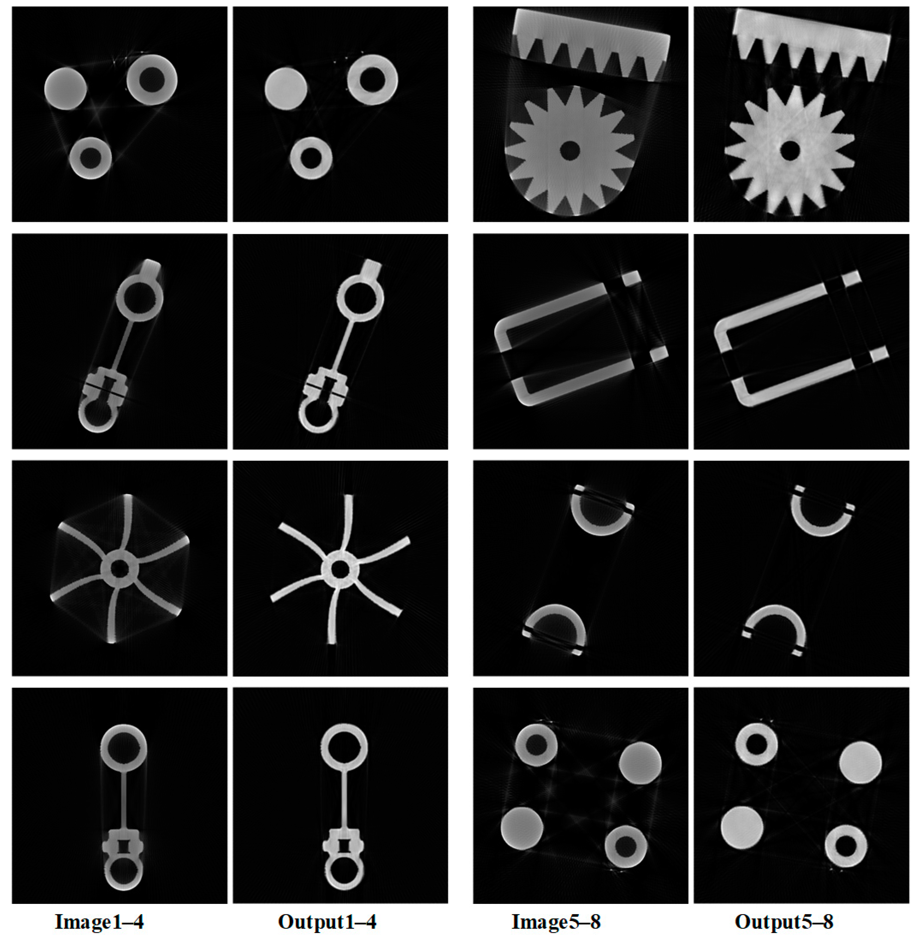
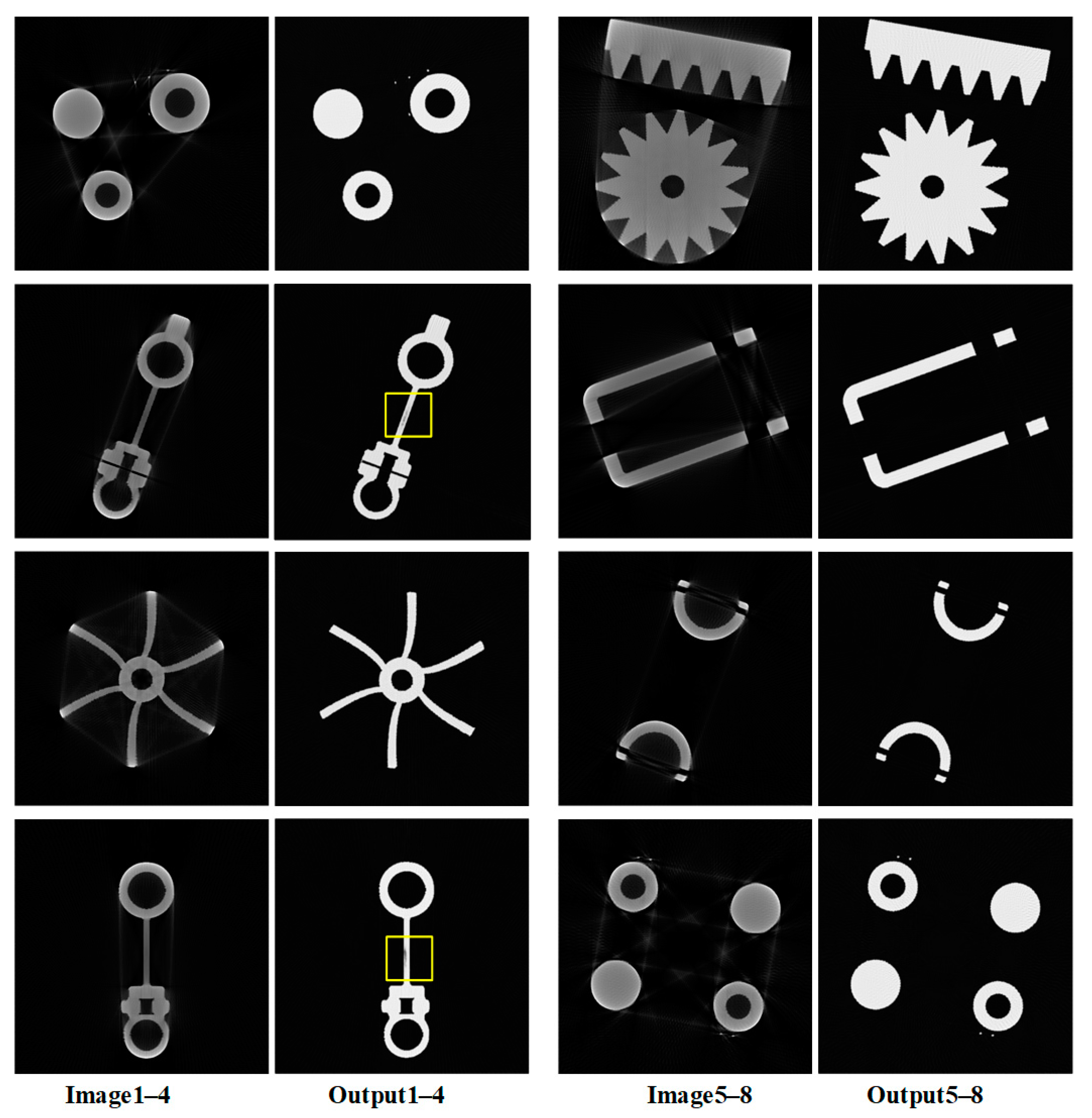
3.1.3. Ablation Study
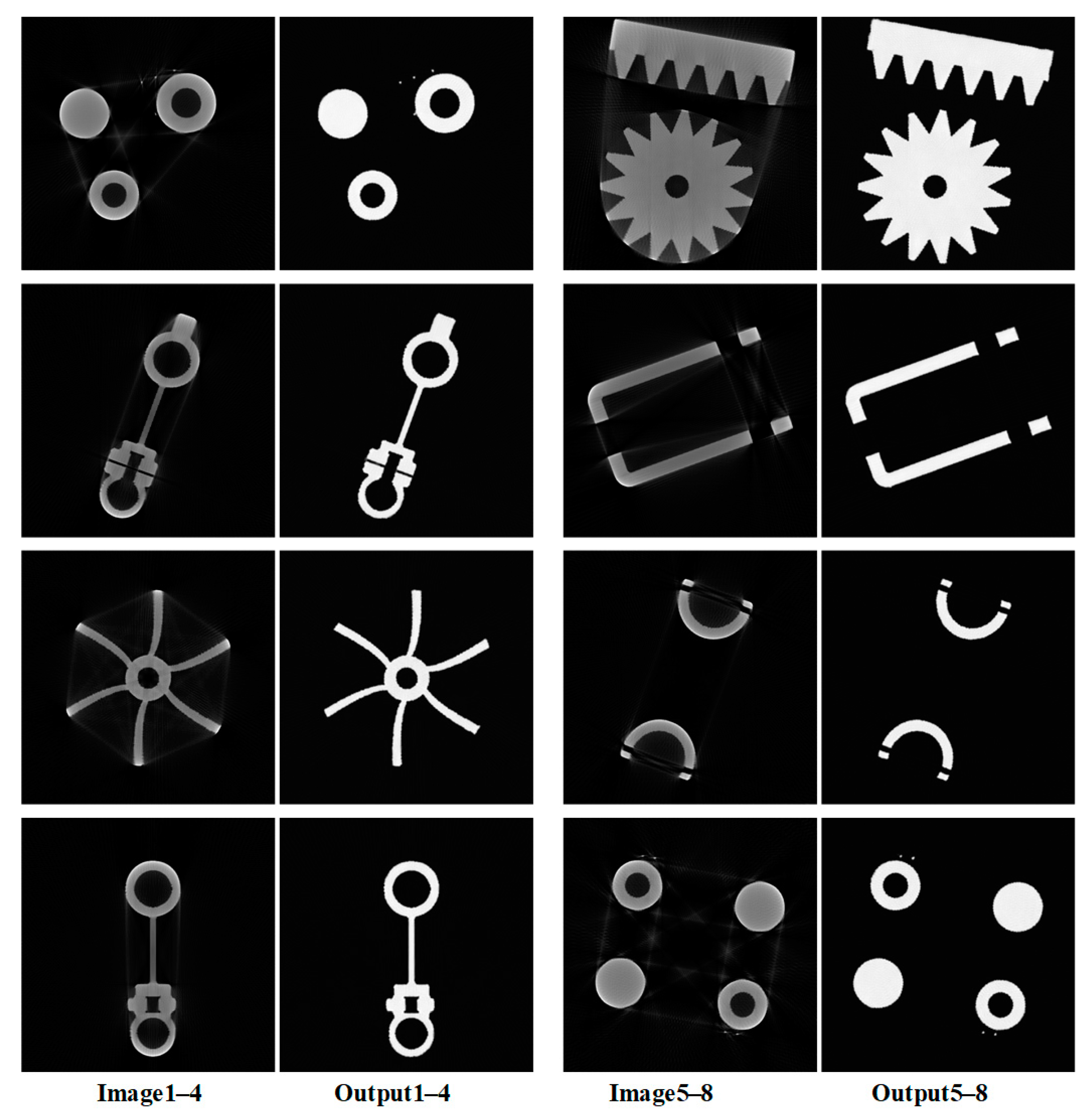
3.2. Results
4. Discussion
5. Conclusions
Author Contributions
Funding
Data Availability Statement
Conflicts of Interest
References
- Withers, P.J.; Bouman, C.A.; Carmignato, S.; Cnudde, V.; Grimaldi, D.; Hagen, C.K.; Maire, E.; Manley, M.; Du Plessis, A.; Stock, S.R. Stock. X-ray computed tomography. Nat. Rev. Methods Primers 2021, 1, 18. [Google Scholar] [CrossRef]
- Hampel, U. X-ray computed tomography. In Industrial Tomography; Woodhead Publishing: Sawston, UK, 2022; pp. 207–229. [Google Scholar]
- Boas, F.E.; Fleischmann, D. CT artifacts: Causes and reduction techniques. Imaging Med. 2012, 4, 229–240. [Google Scholar] [CrossRef]
- Gu, J.; Zhang, L.; Chen, Z.; Xing, Y.; Huang, Z. A method based on interpolation for metal artifacts reduction in CT images. J. X-ray Sci. Technol. 2006, 14, 11–19. [Google Scholar]
- Acharya, R.; Kumar, U.; Patankar, V.H.; Kar, S.; Dash, A. Reducing Metal Artifact using Iterative Reconstruction in Industrial CT. In Proceedings of the 2021 4th Biennial International Conference on Nascent Technologies in Engineering (ICNTE), Navi Mumbai, India, 15–16 January 2021; pp. 1–6. [Google Scholar]
- Paudel, M.R.; Mackenzie, M.; Fallone, B.G.; Rathee, S. Evaluation of metal artifacts in MVCT systems using a model based correction method. Med. Phys. 2012, 39, 6297–6308. [Google Scholar] [CrossRef] [PubMed]
- Hokamp, N.G.; Eck, B.; Siedek, F.; Dos Santos, D.P.; Holz, J.A.; Maintz, D.; Haneder, S. Quantification of metal artifacts in computed tomography: Methodological considerations. Quant. Imaging Med. Surg. 2020, 10, 1033. [Google Scholar] [CrossRef] [PubMed]
- Anhaus, J.A.; Killermann, P.; Sedlmair, M.; Winter, J.; Mahnken, A.H.; Hofmann, C. Nonlinearly scaled prior image-controlled frequency split for high-frequency metal artifact reduction in computed tomography. Med. Phys. 2022, 49, 5870–5885. [Google Scholar] [CrossRef] [PubMed]
- Arabi, H.; Zaidi, H. Deep learning–based metal artefact reduction in PET/CT imaging. Eur. Radiol. 2021, 31, 6384–6396. [Google Scholar] [CrossRef] [PubMed]
- Zhang, Y.; Yu, H. Convolutional neural network based metal artifact reduction in x-ray computed tomography. IEEE Trans. Med. Imaging 2018, 37, 1370–1381. [Google Scholar] [CrossRef] [PubMed]
- Zhang, Y.; Chu, Y.; Yu, H. Reduction of metal artifacts in x-ray CT images using a convolutional neural network. In Proceedings of the Developments in X-ray Tomography XI. SPIE, San Diego, CA, USA, 6–10 August 2017; Volume 10391, pp. 136–146. [Google Scholar]
- Huang, X.; Wang, J.; Tang, F.; Zhong, T.; Zhang, Y. Metal artifact reduction on cervical CT images by deep residual learning. Biomed. Eng. Online 2018, 17, 1–15. [Google Scholar] [CrossRef] [PubMed]
- Ghani, M.U.; Karl, W.C. Deep learning based sinogram correction for metal artifact reduction. Electron. Imaging 2018, 2018, 472-1–472-8. [Google Scholar] [CrossRef]
- Lyu, Y.; Fu, J.; Peng, C.; Zhou, S.K. U-DuDoNet: Unpaired dual-domain network for CT metal artifact reduction. In Proceedings of the Medical Image Computing and Computer Assisted Intervention–MICCAI 2021: 24th International Conference, Strasbourg, France, 27 September–1 October 2021; Proceedings, Part VI 24. Springer International Publishing: Cham, Switzerland, 2021; pp. 296–306. [Google Scholar]
- Zhang, X.; Wang, J.; Xing, L. Metal artifact reduction in X-ray computed tomography (CT) by constrained optimization. Med. Phys. 2011, 38, 701–711. [Google Scholar] [CrossRef] [PubMed]
- Wang, H.; Li, Y.; Zhang, H.; Meng, D.; Zheng, Y. InDuDoNet+: A deep unfolding dual domain network for metal artifact reduction in CT images. Med. Image Anal. 2023, 85, 102729. [Google Scholar] [CrossRef] [PubMed]
- Busi, M.; Kehl, C.; Frisvad, J.R.; Olsen, U.L. Metal artifact reduction in spectral X-ray CT using spectral deep learning. J. Imaging 2022, 8, 77. [Google Scholar] [CrossRef] [PubMed]
- Yu, L.; Zhang, Z.; Li, X.; Xing, L. Deep sinogram completion with image prior for metal artifact reduction in CT images. IEEE Trans. Med. Imaging 2020, 40, 228–238. [Google Scholar] [CrossRef] [PubMed]
- Hegazy, M.A.A.; Cho, M.H.; Cho, M.H.; Lee, S.Y. U-net based metal segmentation on projection domain for metal artifact reduction in dental CT. Biomed. Eng. Lett. 2019, 9, 375–385. [Google Scholar] [CrossRef] [PubMed]
- Wang, H.; Xie, Q.; Zeng, D.; Ma, J.; Meng, D.; Zheng, Y. OSCNet: Orientation-Shared Convolutional Network for CT Metal Artifact Learning. IEEE Trans. Med. Imaging 2023, 43, 489–502. [Google Scholar] [CrossRef] [PubMed]
- Alom, M.Z.; Hasan, M.; Yakopcic, C.; Taha, T.M.; Asari, V.K. Recurrent residual convolutional neural network based on u-net (r2u-net) for medical image segmentation. arXiv 2018, arXiv:1802.06955. [Google Scholar]
- He, K.; Zhang, X.; Ren, S.; Sun, J. Deep residual learning for image recognition. In Proceedings of the IEEE Conference on Computer Vision and Pattern Recognition, Las Vegas, NV, USA, 26 June–1 July 2016; pp. 770–778. [Google Scholar]
- Jiang, S.; Sun, Y.; Xu, S.; Wu, Z. Metal artifact correction of CT images based on Generative Adversarial Networks. J. Harbin Eng. Univ. 2022, 43, 1766–1771. [Google Scholar]
- Zhong, X.Y.; Wang, Y.Z.; Cai, A.L.; Liang, N.N.; Li, L.; Yan, B. Dual-Energy CT Image Super-resolution via Generative Adversarial Network. In Proceedings of the 2021 International Conference on Artificial Intelligence and Electromechanical Automation (AIEA), Guangzhou, China, 14–16 May 2021; pp. 343–347. [Google Scholar]
- Yang, H.H.; Yang, C.H.H.; Tsai, Y.C.J. Y-net: Multi-scale feature aggregation network with wavelet structure similarity loss function for single image dehazing. In Proceedings of the ICASSP 2020-2020 IEEE International Conference on Acoustics, Speech and Signal Processing (ICASSP), Barcelona, Spain, 4–8 May 2020; pp. 2628–2632. [Google Scholar]
- Lin, W.A.; Liao, H.; Peng, C.; Sun, X.; Zhang, J.; Luo, J.; Chellappa, R.; Zhou, S.K. Dudonet: Dual domain network for ct metal artifact reduction. In Proceedings of the IEEE/CVF Conference on Computer Vision and Pattern Recognition, Long Beach, CA, USA, 16–17 June 2019; pp. 10512–10521. [Google Scholar]


| Parameter | Numeric Value |
|---|---|
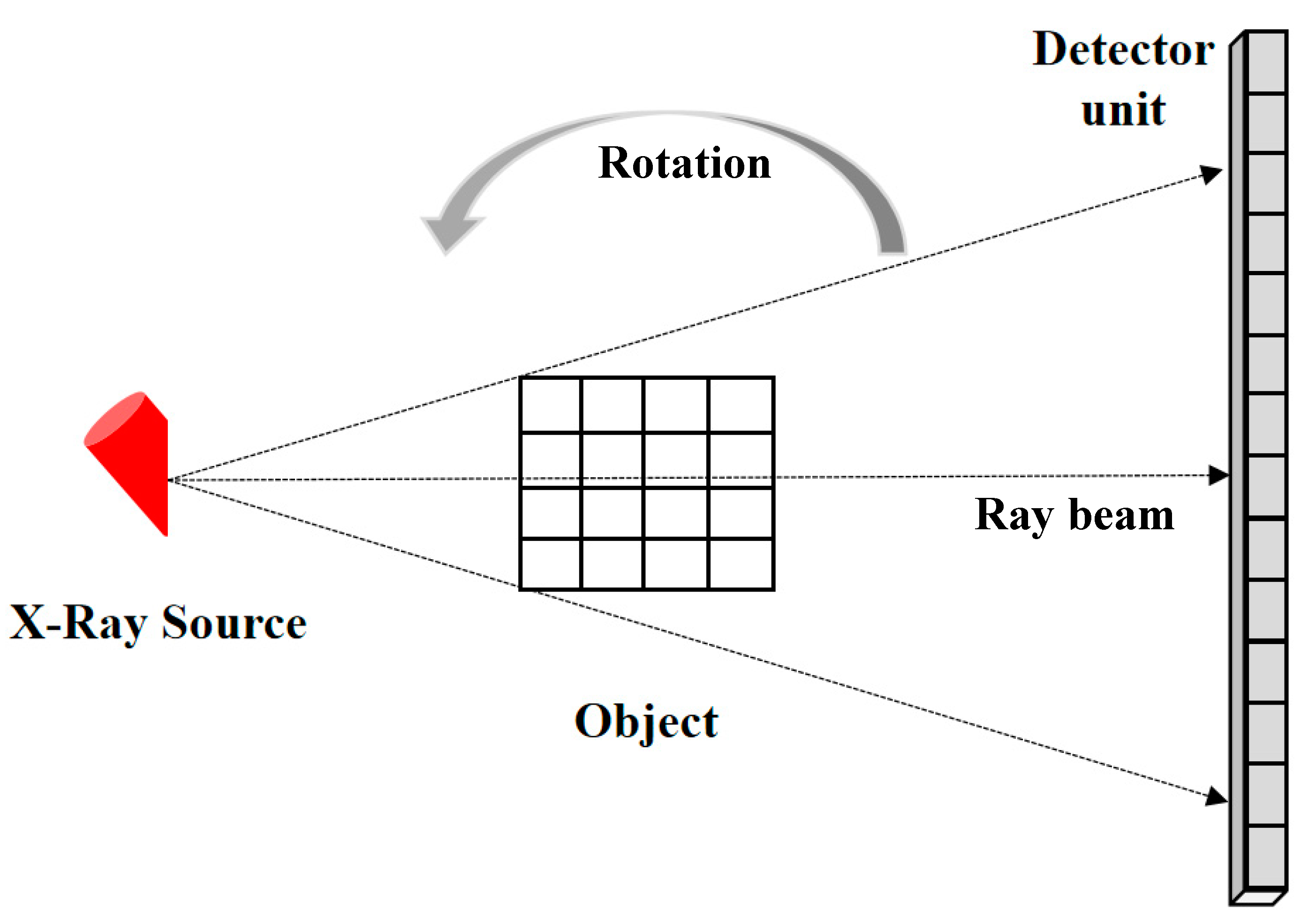
| Source-to-detector distance | 1200 (mm) |
| Source-to-rotation distance | 600 (mm) |
| Object size | 512 × 512 |
| Pixel size | 0.1 × 0.1 (mm2) |
| Number of detector units | 704 × 1 |
| Detector size | 0.1 × 0.1 (mm2) |
| Projection angles | 320 |
| Joint Network | UNet | ResNet | ||||
|---|---|---|---|---|---|---|
| Metrics | PSNR | SSIM | PSNR | SSIM | PSNR | SSIM |
| Image 1 | 39.07 | 0.960 | 24.50 | 0.816 | 36.74 | 0.956 |
| Image 2 | 36.97 | 0.971 | 28.05 | 0.829 | 34.69 | 0.946 |
| Image 3 | 35.67 | 0.966 | 27.65 | 0.782 | 32.44 | 0.952 |
| Image 4 | 33.90 | 0.970 | 28.82 | 0.851 | 29.28 | 0.944 |
| Image 5 | 29.94 | 0.857 | 22.39 | 0.657 | 26.57 | 0.874 |
| Image 6 | 32.99 | 0.962 | 27.80 | 0.801 | 28.95 | 0.948 |
| Image 7 | 41.23 | 0.985 | 27.12 | 0.875 | 37.69 | 0.977 |
| Image 8 | 39.25 | 0.952 | 25.21 | 0.758 | 36.17 | 0.949 |
| Average | 36.13 | 0.953 | 26.44 | 0.796 | 32.82 | 0.943 |
| Joint Network | ResNet | |||
|---|---|---|---|---|
| Metrics | PSNR | SSIM | PSNR | SSIM |
| Image 1 | 33.75 | 0.956 | 31.83 | 0.944 |
| Image 2 | 34.59 | 0.960 | 26.90 | 0.885 |
| Image 3 | 35.25 | 0.951 | 32.81 | 0.933 |
| Image 4 | 34.32 | 0.967 | 25.32 | 0.852 |
| Average | 34.48 | 0.959 | 29.22 | 0.904 |
Disclaimer/Publisher’s Note: The statements, opinions and data contained in all publications are solely those of the individual author(s) and contributor(s) and not of MDPI and/or the editor(s). MDPI and/or the editor(s) disclaim responsibility for any injury to people or property resulting from any ideas, methods, instructions or products referred to in the content. |
© 2024 by the authors. Licensee MDPI, Basel, Switzerland. This article is an open access article distributed under the terms and conditions of the Creative Commons Attribution (CC BY) license (https://creativecommons.org/licenses/by/4.0/).
Share and Cite
Jiang, S.; Sun, Y.; Xu, S.; Zhang, Z.; Wu, Z. Metal Artifact Correction in Industrial CT Images Based on a Dual-Domain Joint Deep Learning Framework. Appl. Sci. 2024, 14, 3261. https://doi.org/10.3390/app14083261
Jiang S, Sun Y, Xu S, Zhang Z, Wu Z. Metal Artifact Correction in Industrial CT Images Based on a Dual-Domain Joint Deep Learning Framework. Applied Sciences. 2024; 14(8):3261. https://doi.org/10.3390/app14083261
Chicago/Turabian StyleJiang, Shibo, Yuewen Sun, Shuo Xu, Zehuan Zhang, and Zhifang Wu. 2024. "Metal Artifact Correction in Industrial CT Images Based on a Dual-Domain Joint Deep Learning Framework" Applied Sciences 14, no. 8: 3261. https://doi.org/10.3390/app14083261
APA StyleJiang, S., Sun, Y., Xu, S., Zhang, Z., & Wu, Z. (2024). Metal Artifact Correction in Industrial CT Images Based on a Dual-Domain Joint Deep Learning Framework. Applied Sciences, 14(8), 3261. https://doi.org/10.3390/app14083261