
Energy Harvester Based on a Rotational Pendulum Supported with FEM

 ,
,  ,
,  , and
, and
Abstract
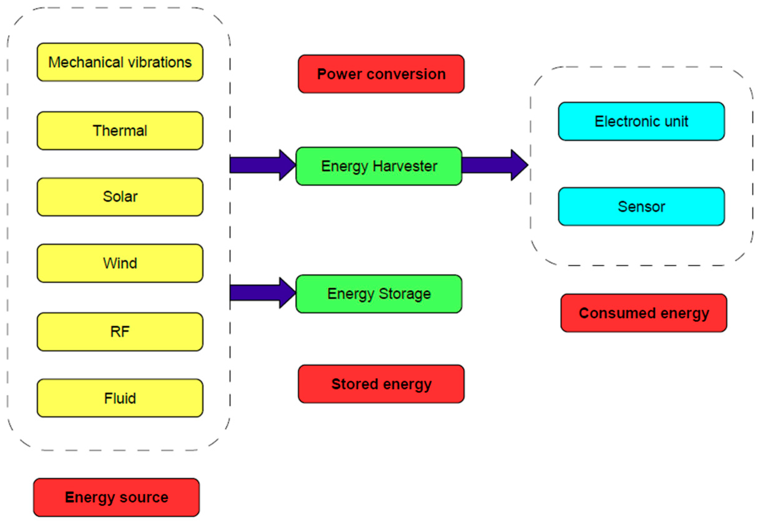
1. Introduction
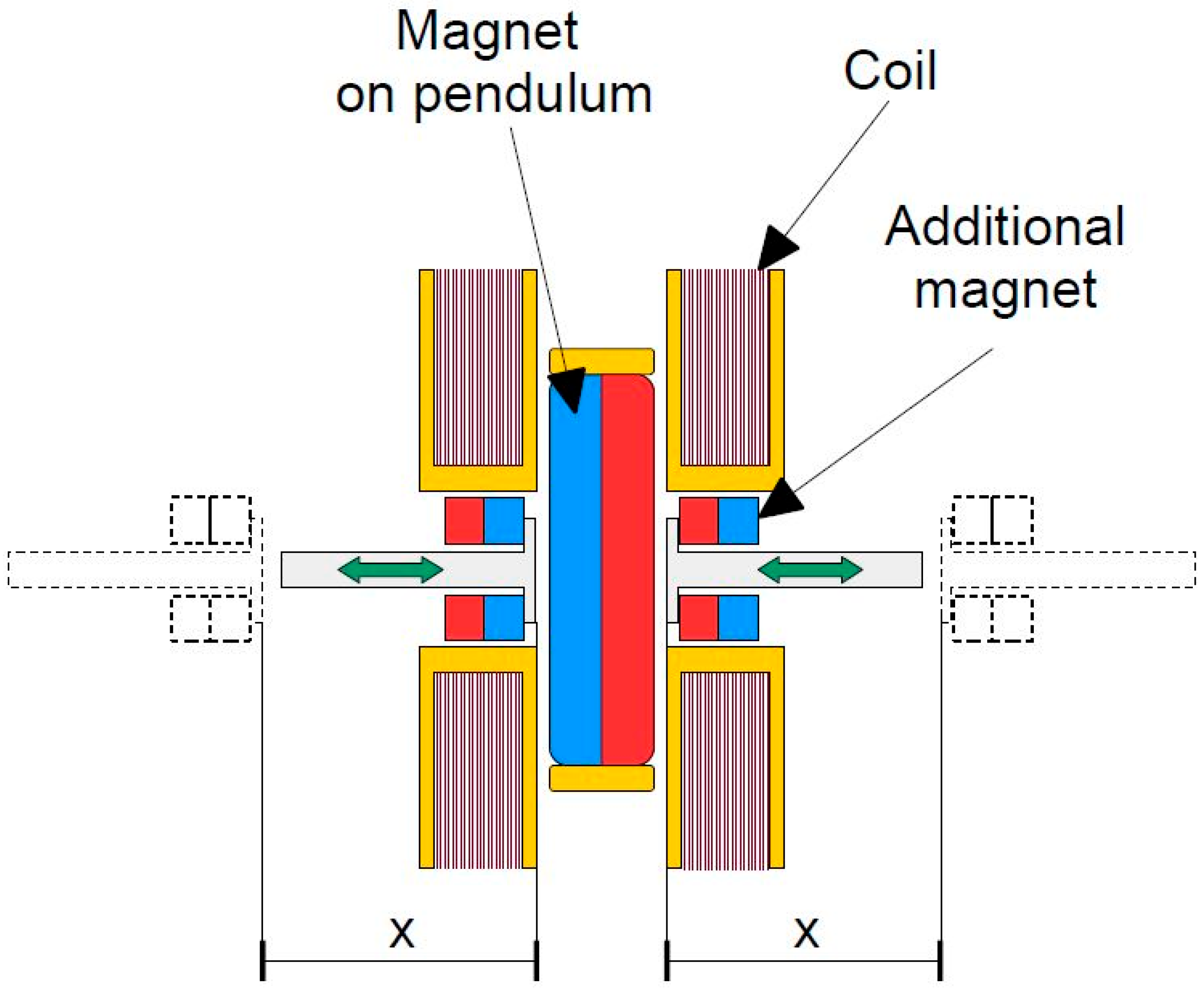
2. The Concept of Pendulum-Based Electromagnetic Energy Harvesting Systems
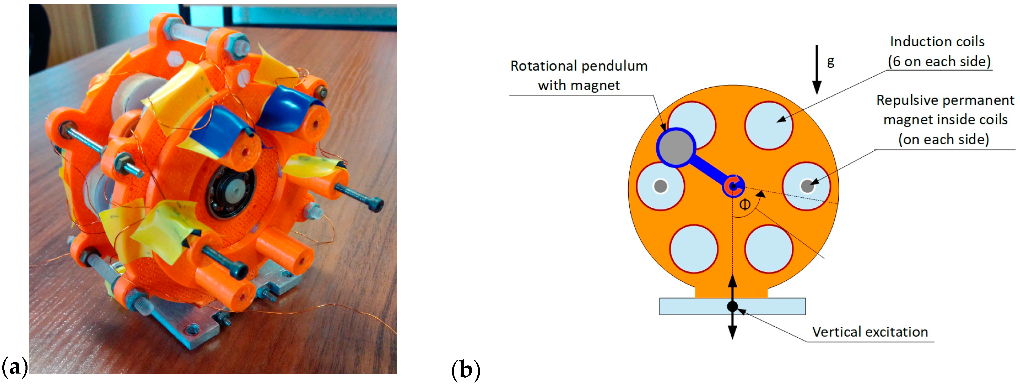
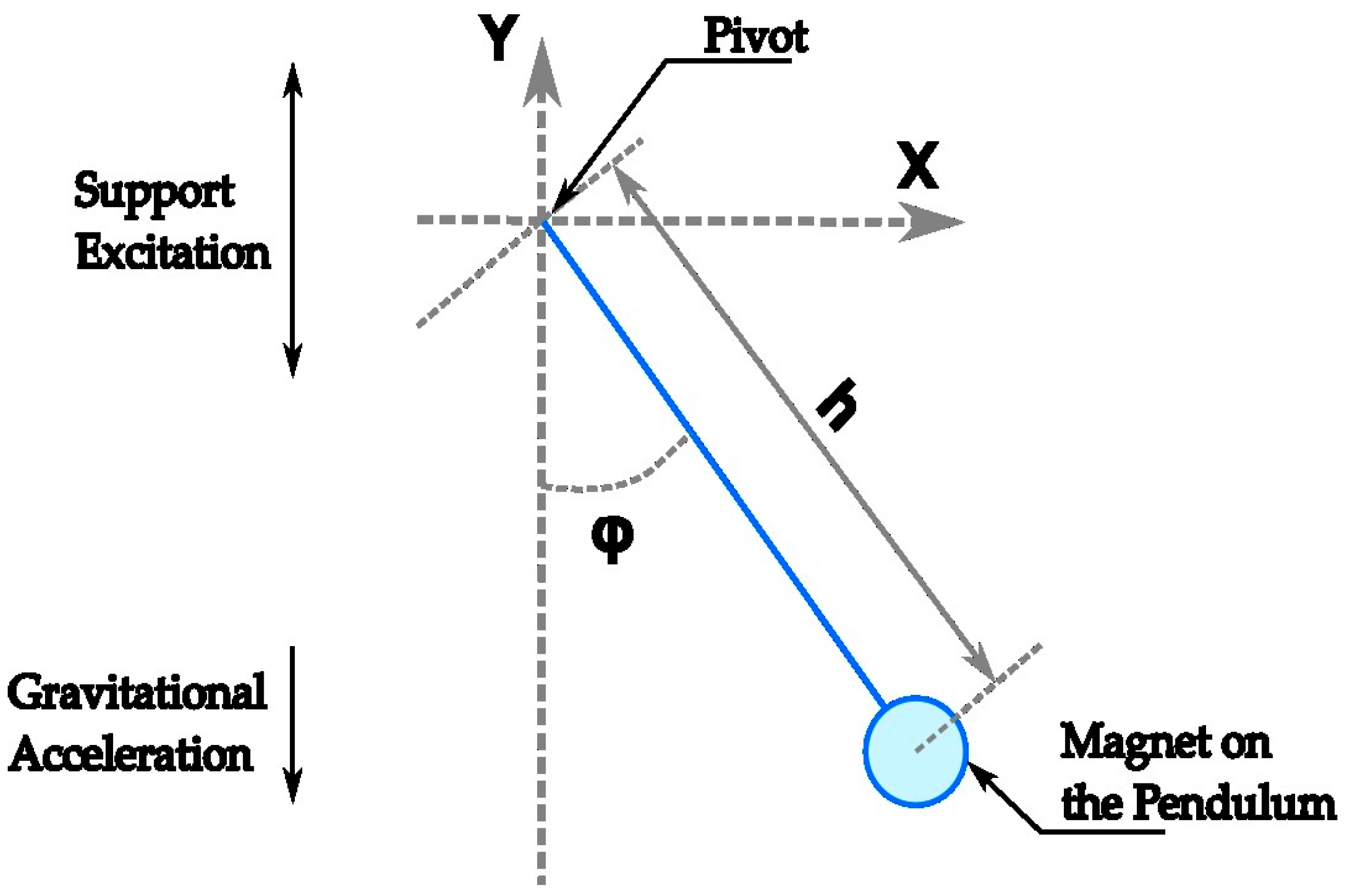
3. Design and Modeling of an Energy Harvesting System with a Rotational Pendulum
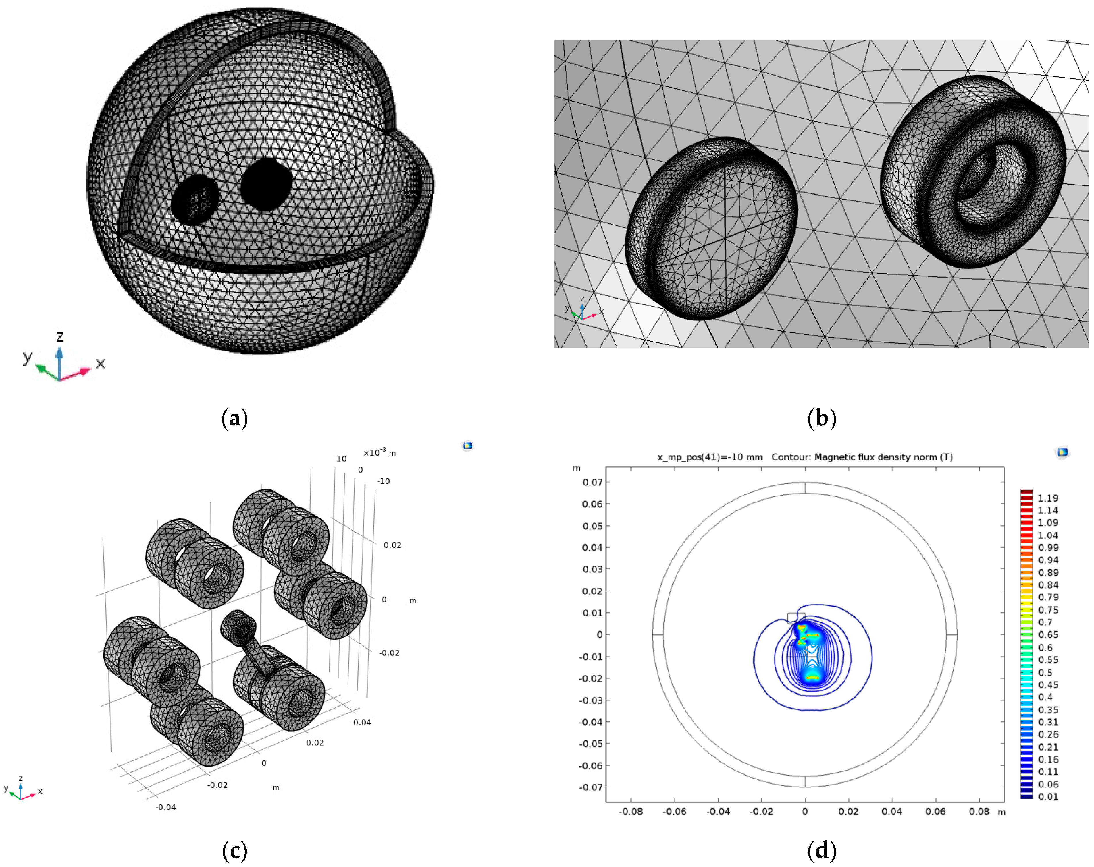
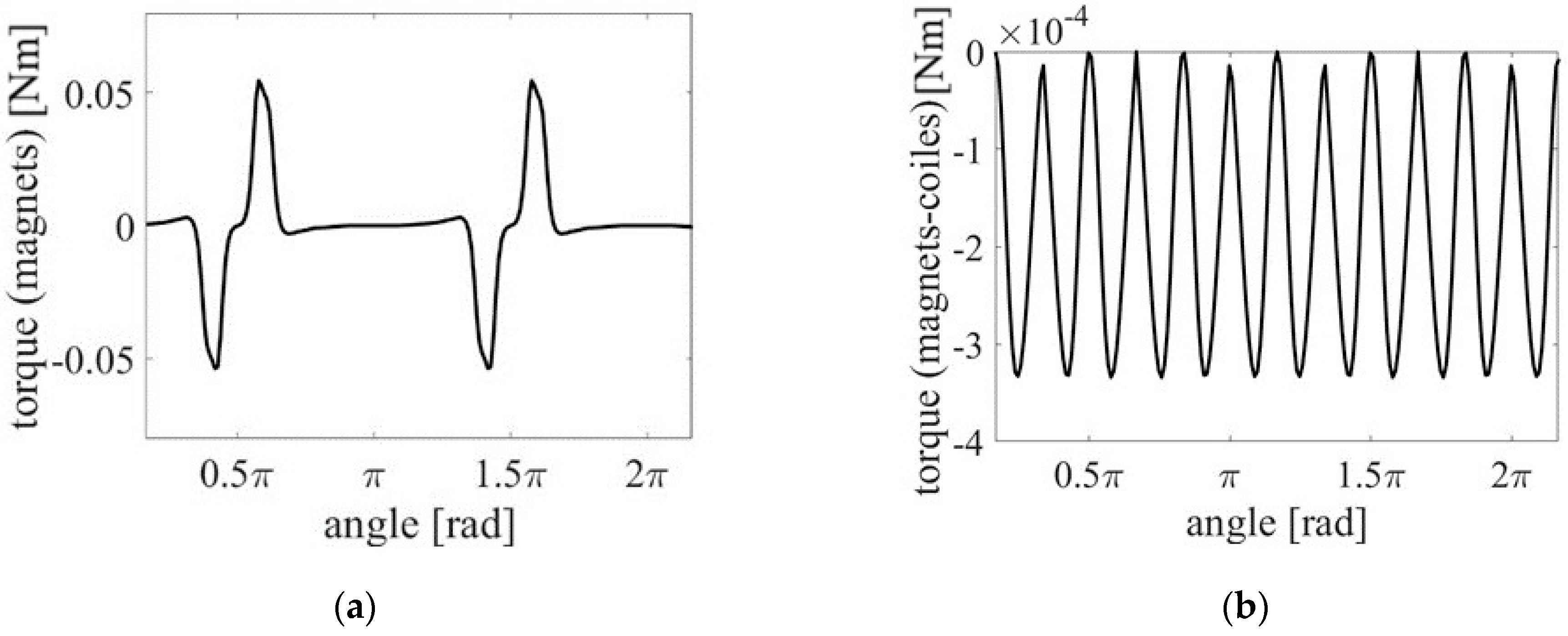
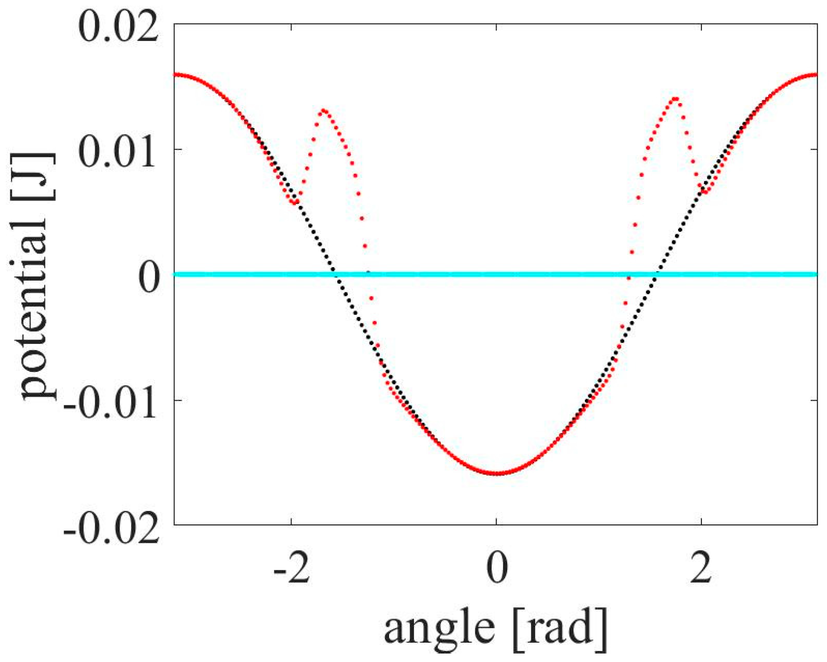
3.1. Electromagnetic FEM Model
3.2. Reduced Mathematical Model
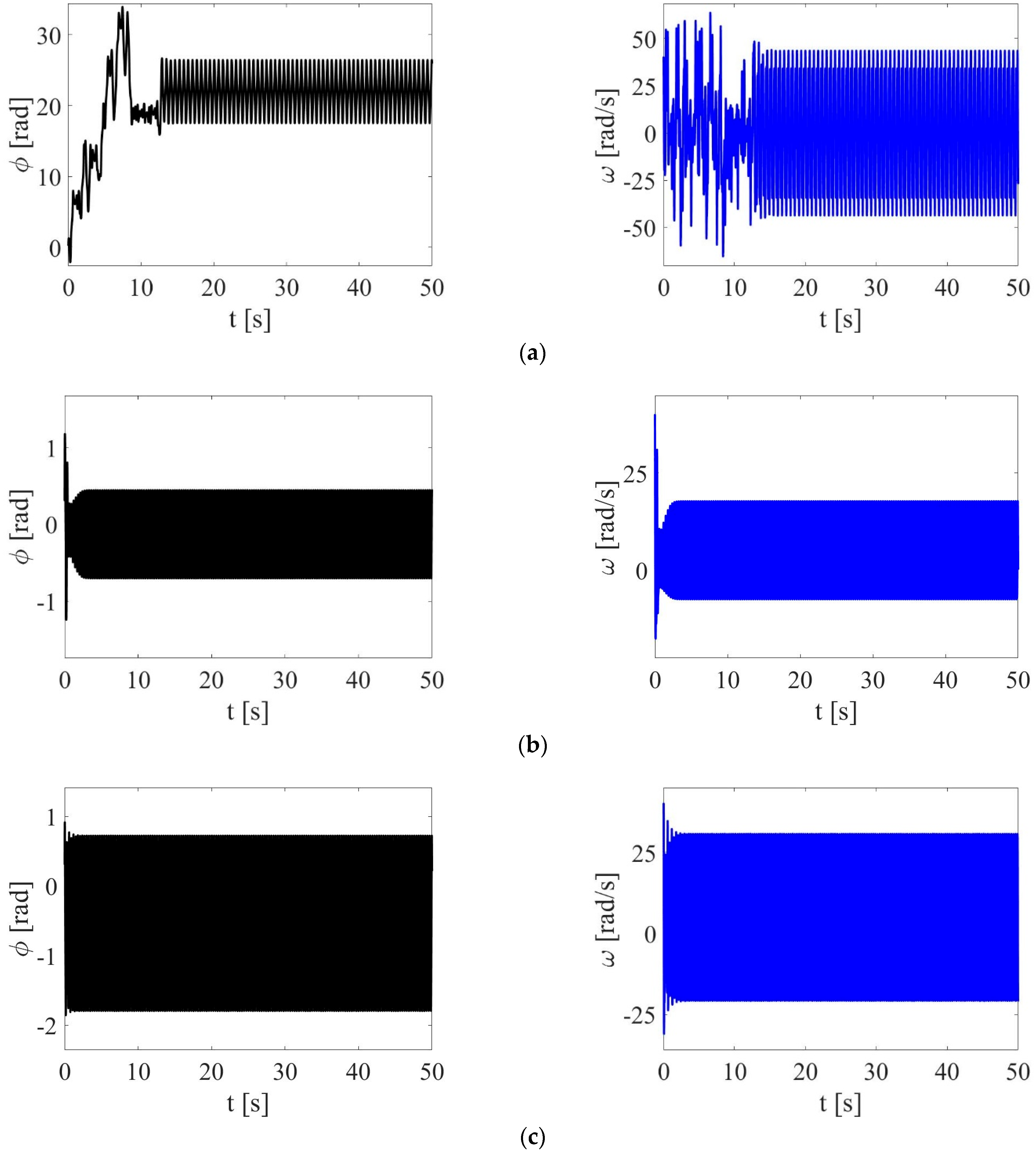
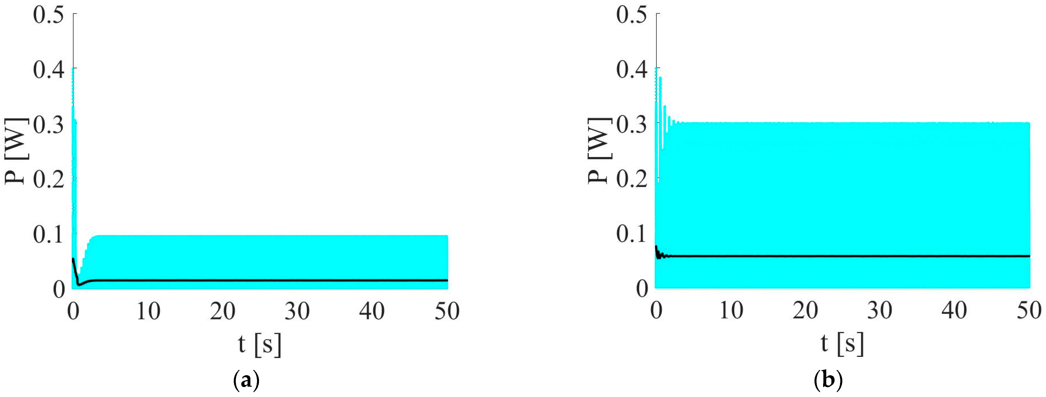
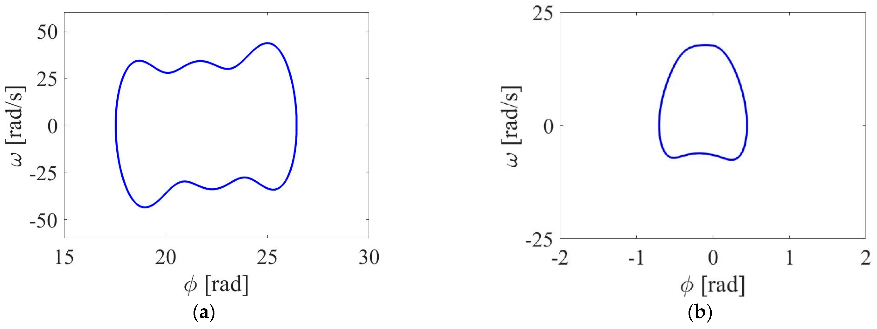
4. Numerical Simulations
- (a)
- System without coils and without magnets, only pendulum with magnet (only gravitational acceleration): α = 0, β = 0.
- (b)
- System with coils and pendulum with magnet (only magnet–coil coupling): α = 0, β = 1,
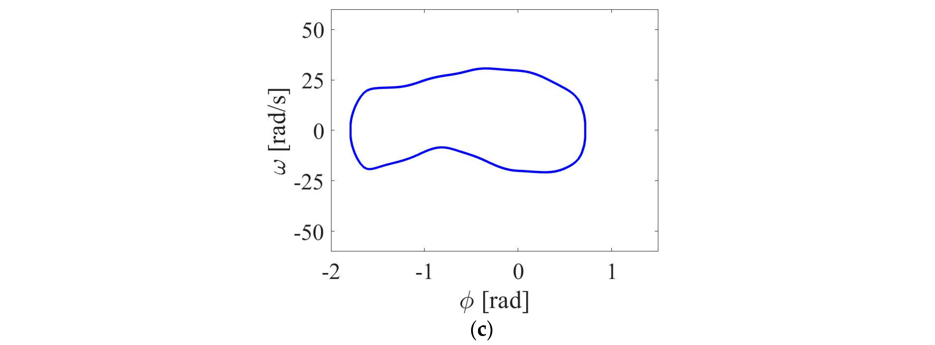
- (c)
- System with all magnets and coils.
5. Conclusions
Supplementary Materials
Author Contributions
Funding
Institutional Review Board Statement
Informed Consent Statement
Data Availability Statement
Acknowledgments
Conflicts of Interest
References
- Kaźmierski, T.J.; Beeby, S. Energy Harvesting Systems, Principles, Modelling and Applications; Springer: New York, NY, USA, 2011. [Google Scholar]
- Priya, S.; Inman, D.J. Energy Harvesting Technologies; Springer: Blacksburg, VA, USA, 2009. [Google Scholar]
- Elvin, N.; Erturk, A. Advances in Energy Harvesting Methods; Springer: New York, NY, USA, 2013. [Google Scholar]
- Yang, T.; Zhou, S.; Litak, G.; Jing, X. Recent advances in correlation and integration between vibration control, energy harvesting and monitoring. Nonlinear Dyn. 2023, 111, 20525–20562. [Google Scholar] [CrossRef]
- Alegret, R.N.; Aragones, R.; Oliver, J.; Ferrer, C. Exploring IIoT and Energy Harvesting Boundaries. In Proceedings of the IECON 2019—45th Annual Conference of the IEEE Industrial Electronics Society, Lisbon, Portugal, 14–17 October 2019; pp. 6732–6736. [Google Scholar] [CrossRef]
- Zeadally, S.; Shaikh, F.K.; Talpur, A.; Sheng, Q.Z. Design architectures for energy harvesting in the Internet of Thing. Renew. Sustain. Energy Rev. 2020, 128, 109901. [Google Scholar] [CrossRef]
- Ambrożkiewicz, B.; Litak, G.; Wolszczak, P. Modelling of electromagnetic energy harvester with rotational pendulum using mechanical vibrations to scavenge electrical energy. Appl. Sci. 2020, 10, 671. [Google Scholar] [CrossRef]
- He, J.; Wen, T.; Qian, S.; Zhang, Z.; Tian, Z.; Zhu, J.; Mu, J.; Hou, X.; Geng, W.; Cho, J.; et al. Triboelectric-piezoelectric-electromagnetic hybrid nanogenerator for high-efficient vibration energy harvesting and self-powered wireless monitoring system. Nano Energy 2018, 43, 326–339. [Google Scholar] [CrossRef]
- Zhang, B.; Zhang, Q.; Wang, W.; Han, J.; Tang, X.; Gu, F.; Ball, A.D. Dynamic modelling and structural optimization of a bistable electromagnetic vibration energy harvester. Energies 2019, 12, 2410. [Google Scholar] [CrossRef]
- Cottone, F.; Vocca, H.; Gammaitoni, L. Nonlinear energy harvesting. Phys. Rev. Lett. 2009, 102, 080601. [Google Scholar] [CrossRef] [PubMed]
- Erturk, A.; Inman, D.J. An experimentally validated bimorph cantilever model for piezoelectric energy harvesting from base excitations. Smart Mater. Struct. 2009, 18, 025009. [Google Scholar] [CrossRef]
- Tvedt, L.G.W.; Nguyen, D.S.; Halvorsen, E. Nonlinear behaviour of an electrostatic energy harvester under wide- and narrowband excitation. J. Microelectromech. Syst. 2010, 19, 305–316. [Google Scholar] [CrossRef]
- Zhang, Y.; Wang, T.; Luo, A.; Hu, Y.; Li, X.; Wang, F. Micro electrostatic energy harvester with both broad bandwidth and high normalized power density. Appl. Energy 2018, 212, 362–371. [Google Scholar] [CrossRef]
- Rubes, O.; Brablc, M.; Hadas, Z. Nonlinear vibration energy harvester: Design and oscillating stability analyses. Mech. Syst. Signal Process. 2019, 125, 170–184. [Google Scholar] [CrossRef]
- Aravindan, M.; Ali, S.F. Exploring 1:3 internal resonance for broadband piezoelectric energy harvesting. Mech. Syst. Signal Process. 2021, 153, 107493. [Google Scholar] [CrossRef]
- Haroun, A.; Yamada, I.; Warisawa, S. Study of electromagnetic vibration energy harvesting with free/impact motion for low frequency operation. J. Sound Vib. 2015, 349, 389–402. [Google Scholar] [CrossRef]
- Phan, N.P.; Bader, S.; Oelmann, B. Performance of an electromagnetic energy harvester with linear and nonlinear springs under real vibrations. Sensors 2020, 20, 5456. [Google Scholar] [CrossRef] [PubMed]
- Pepe, G.; Dorla, A.; Roveri, N.; Carcaterra, A. Vibration energy harvesting for cars: Semi-active piezo controllers. Arch. Appl. Mech. 2023, 93, 663–685. [Google Scholar] [CrossRef]
- Cahill, P.; Hazra, B.; Karoumi, R.; Mathewson, A.; Pakrashi, V. Vibration energy harvesting based monitoring of an operational bridge undergoing forced vibration and train passage. Mech. Syst. Signal Process. 2018, 106, 265–283. [Google Scholar] [CrossRef]
- Fan, W.; Zhang, C.; Liu, Y.; Wang, S.; Dong, K.; Li, Y.; Wu, F.; Liang, J.; Wang, C.; Zhang, Y. An ultra-thin piezoelectric nanogenerator with breathable, superhydrophobic, and antibacterial properties for human motion monitoring. Nano Res. 2023, 16, 11612–11620. [Google Scholar] [CrossRef]
- Huang, D.; Zhou, S.; Han, Q.; Litak, G. Response analysis of the nonlinear vibration energy harvester with an uncertain parameter. Proc. Inst. Mech. Eng. Part K J. Multi-Body Dyn. 2020, 234, 393–407. [Google Scholar] [CrossRef]
- Malaji, P.V.; Ali, S.F. Broadband energy harvesting with mechanically coupled harvesters. Sens. Actuators A 2017, 255, 1–9. [Google Scholar] [CrossRef]
- Kullah, H.; Najafi, K. Energy Scavenging from Low-Frequency Vibrations by Using Frequency Up-Conversion for Wireless Sensor Applications. IEEE Sens. J. 2008, 8, 261–268. [Google Scholar] [CrossRef]
- Jia, Y. Review of nonlinear vibration energy harvesting: Duffing, bistability, parametric, stochastic and others. J. Intell. Mater. Syst. Struct. 2020, 31, 921–944. [Google Scholar] [CrossRef]
- Giri, A.M.; Ali, S.F.; Arockiarajan, A. Characterizing harmonic and subharmonic solutions of the bi-stable piezoelectric harvester with a modified harmonic balance approach. Mech. Syst. Signal Process. 2023, 198, 110437. [Google Scholar] [CrossRef]
- Ferrari, M.; Ferrari, V.; Guizzetti, M.; Ando, B.; Baglio, S.; Trigona, C. Improved energy harvesting from wideband vibrations by nonlinear piezoelectric converters. Sens. Actuators A Phys. 2010, 162, 425–431. [Google Scholar] [CrossRef]
- Huguet, T.; Badel, A.; Lallart, M. Exploiting bistable oscillator subharmonics for magnified broadband vibration energy harvesting. Appl. Phys. Lett. 2017, 111, 173905. [Google Scholar] [CrossRef]
- Pellegrini, S.P.; Tolou, N.; Schenk, M.; Herder, J.L. Bistable vibration energy harvesters: A review. J. Intell. Mater. Syst. Struct. 2013, 24, 1303–1312. [Google Scholar] [CrossRef]
- Giri, A.M.; Ali, S.F.; Arockiarajan, A. Influence of asymmetric potential on multiple solutions of the bi-stable piezoelectric harvester. Eur. Phys. J. Spec. Top. 2022, 231, 1443–1464. [Google Scholar] [CrossRef]
- Dong, L.; Closson, A.B.; Jin, C.; Trase, I.; Chen, Z.; Zhang, J.X.J. Vibration-Energy-Harvesting System: Transduction Mechanics, Frequency Tuning Techniques and Biomechanical Applications. Adv. Mater. Technol. 2019, 4, 1900177. [Google Scholar] [CrossRef] [PubMed]
- Bouhedma, S.; Rao, Y.; Schutz, A.; Yuan, C.; Hu, S.; Lange, F.; Bechtold, T.; Hohfeld, D. System-Level Model and Simulation of a Frequency-Tunable Vibration Energy Harvester. Micromachines 2020, 11, 91. [Google Scholar] [CrossRef] [PubMed]
- Huguet, T.; Lallart, M.; Badel, A. Orbit jump in bistable energy harvesters through buckling level modification. Mech. Syst. Signal Process. 2019, 128, 202–215. [Google Scholar] [CrossRef]
- Lee, S.; Lee, Y.; Dongseob, K.; Yan, Y.; Lin, L.; Lin, Z.H.; Hwang, W.; Wang, Z.L. Triboelectric nanogenerator for harvesting pendulum oscillation energy. Nano Energy 2013, 2, 1113–1120. [Google Scholar] [CrossRef]
- Xu, J.; Tang, J. Multi-directional energy harvesting by piezoelectric cantilever-pendulum with internal resonance. Appl. Phys. Lett. 2015, 107, 213902. [Google Scholar] [CrossRef]
- Wu, Y.; Qiu, J.; Shengpeng, Z.; Ji, H.; Chen, Y.; Li, S. A piezoelectric spring pendulum oscillator used for multi-directional and ultra-low frequency vibration energy harvesting. Appl. Energy 2018, 231, 600–614. [Google Scholar] [CrossRef]
- Wang, Y.J.; Chen, C.D.; Sung, C.K. Design of a frequency-adjusting device for harvesting energy from a rotating wheel. Sens. Actuators A 2010, 159, 196–203. [Google Scholar] [CrossRef]
- Naifar, S.; Bradai, S.; Viehweger, C.; Kanoun, O. Survey of electromagnetic and magnetoelectric vibration energy harvesters for low frequency excitation. Measurement 2017, 106, 251–263. [Google Scholar] [CrossRef]
- Yurchenko, D.; Alevras, P. Parametric pendulum based wave energy converter. Mech. Syst. Signal Process. 2018, 99, 504–515. [Google Scholar] [CrossRef]
- Malaji, P.V.; Ali, S.F. Analysis of energy harvesting from multiple pendulums with and without mechanical coupling. Eur. Phys. J. Spec. Top. 2015, 224, 2823–2838. [Google Scholar] [CrossRef]
- Malaji, P.V.; Doddi, S.; Friswell, M.I.; Adhikari, S. Analysis of pendulums coupled by torsional springs for energy harvesting. MATEC Web Conf. 2018, 211, 05008. [Google Scholar] [CrossRef][Green Version]
- Kuang, Y.; Hide, R.; Zhu, M. Broadband energy harvesting by nonlinear magnetic rolling pendulum with sub-harmonic resonance. Appl. Energy 2019, 255, 113822. [Google Scholar] [CrossRef]
- Dai, X. An vibration energy harvester with broadband and frequency-doubling characteristics based on rotary pendulums. Sens. Actuators A Phys. 2016, 241, 161–168. [Google Scholar] [CrossRef]
- Koszewnik, A. Analytical Modeling and Experimental validation of an energy harvesting system for the smart plate with and integrated piezo-harvester. Sensors 2019, 19, 812. [Google Scholar] [CrossRef]
- Borowiec, M.; Syta, A.; Litak, G. Energy harvesting optimizing with a magnetostrictive cantilever beam system. Int. J. Struct. Stab. Dyn. 2019, 19, 1941002. [Google Scholar] [CrossRef]
- Smilek, J.; Hadas, Z.; Vetiska, J.; Beeby, S. Rolling mass energy harvester for very low frequency of input vibrations. Mech. Syst. Signal Process. 2019, 125, 215–228. [Google Scholar] [CrossRef]
- Toyabur, R.M.; Salauddin, M.; Cho, H.; Park, J.Y. A multimodal hybrid energy harvester based on piezoelectric-electromagnetic mechanisms for low-frequency ambient vibrations. Energy Convers. Manag. 2018, 168, 454–466. [Google Scholar] [CrossRef]
- Li, Z.; Yan, Z.; Luo, J.; Yang, Z. Performance comparison of electromagnetic energy harvesters based on magnet arrays of alternating polarity and configuration. Energy Convers. Manag. 2019, 179, 132–140. [Google Scholar] [CrossRef]
- Cui, X.; Hu, J. An infrasonic vibration energy harvester using pendulum impact. Int. J. Appl. Electromagn. Mech. 2015, 47, 467–474. [Google Scholar] [CrossRef]
- Avila Bernal, A.G.; Linares Garcia, L.E. The modelling of an electromagnetic energy harvester architecture. Appl. Math. Model. 2012, 36, 4728–4741. [Google Scholar] [CrossRef]


| Mechanical Part | |
| Mass of the system (g) | ~900 |
| Pendulum magnet (mm) | ⌀ 20 (O.D) × 5 (thick) (cylinder) |
| Side magnets (mm) | ⌀ 8 (O.D) × ⌀ 6 (I.D) × 3.5 (thick) (ring) |
| Diameter of rotation (mm) | ⌀ 66.5 |
| Limiting dimensions of the system (mm) | >100 |
| Electrical Part | |
| Number of coils | 12 (connected in series) |
| Coil induction (mH) | 4.545 |
| Number of turns | 253 |
| Coil length (mm) | 8 |
| Wire type | 28 AWG |
| Resistance (Ω) | 30.3 |
| Type of magnets | NdFeB 37 |
| Term | Value |
|---|---|
| I [kg-m2] | 0.000377 |
| m [kg] | 0.0186 |
| g [m/s2] | 9.81 |
| h [m] | 0.03325 |
| α, β | 0 and 1 |
| λ | 0.048 |
| h [m] | 0.034 |
| ω [rad/s] | 15 |
| A [m] | 0.2 |
Disclaimer/Publisher’s Note: The statements, opinions and data contained in all publications are solely those of the individual author(s) and contributor(s) and not of MDPI and/or the editor(s). MDPI and/or the editor(s) disclaim responsibility for any injury to people or property resulting from any ideas, methods, instructions or products referred to in the content. |
© 2024 by the authors. Licensee MDPI, Basel, Switzerland. This article is an open access article distributed under the terms and conditions of the Creative Commons Attribution (CC BY) license (https://creativecommons.org/licenses/by/4.0/).
Share and Cite
Litak, G.; Kondratiuk, M.; Wolszczak, P.; Ambrożkiewicz, B.; Giri, A.M. Energy Harvester Based on a Rotational Pendulum Supported with FEM. Appl. Sci. 2024, 14, 3265. https://doi.org/10.3390/app14083265
Litak G, Kondratiuk M, Wolszczak P, Ambrożkiewicz B, Giri AM. Energy Harvester Based on a Rotational Pendulum Supported with FEM. Applied Sciences. 2024; 14(8):3265. https://doi.org/10.3390/app14083265
Chicago/Turabian StyleLitak, Grzegorz, Mirosław Kondratiuk, Piotr Wolszczak, Bartłomiej Ambrożkiewicz, and Abhijeet M. Giri. 2024. "Energy Harvester Based on a Rotational Pendulum Supported with FEM" Applied Sciences 14, no. 8: 3265. https://doi.org/10.3390/app14083265
APA StyleLitak, G., Kondratiuk, M., Wolszczak, P., Ambrożkiewicz, B., & Giri, A. M. (2024). Energy Harvester Based on a Rotational Pendulum Supported with FEM. Applied Sciences, 14(8), 3265. https://doi.org/10.3390/app14083265