1. Introduction
Wind energy is a clean and sustainable energy source that is gaining popularity in nations around the world. Compared to onshore wind power, offshore wind power enjoys the advantage of abundant resources, leading to great efficiency in power generation, minimal environmental contamination, and no land resources, among other things. The vast ocean makes up 71 percent of the Earth’s land, is rich in natural resources, and has huge potential for development. Offshore wind energy resources are abundant off the coast of China, and can largely solve the problem of insufficient electricity supply in the country. However, different to the European countries, the most of China’s offshore wind farms are located on clayey or silty seabeds [
1].
A monopile is a simple structure with clear force resistance and a high bearing capacity, which makes it the most commonly used foundation for offshore wind turbines. Generally, the offshore wind turbine pile foundations are positioned in a challenging maritime environment. Under the long-term cycle of low-frequency loading, the pile foundation accumulates deformation and permanently destroys the tilt of the superstructure. With the development of deep-sea wind turbines and giants, the production cost of monopiles substantially increases, and traditional large-diameter piles eventually cannot meet the needs of complex loading. To optimize the horizontal bearing capacity of monopile foundations and avoid excessive increases in pile size, relevant researchers proposed a composite monopile foundation [
2,
3,
4]. Skirt–pile foundations are an innovative form of offshore wind power foundation that incorporate a skirt to boost the ultimate bearing capacity. The skirt design is similar to that of the bucket foundation, featuring a capped top and an open bottom. The study of skirt–pile foundations builds upon research on traditional bucket foundations [
5,
6,
7]. The offshore wind power team of Tianjin University [
8,
9,
10] developed a wide and shallow composite foundation for wind conditions and addressed the characteristics of China’s offshore wind farms. Subsequently, the team conducted a series of studies on the dynamic response and bearing performance of pile–bucket composite foundations on this basis [
11,
12,
13,
14,
15]. Recently, the pile–bucket foundation was successfully used in wind farm practices in southeastern China [
16]. Wang et al. [
17] employed a numerical model to scrutinize the factors influencing the bearing capacity of a cylindrical foundation. Xu et al. [
15] conducted experimental and numerical studies on the bearing mode, bearing capacity, and damage mode of pile–bucket foundations under different loads in saturated clay soils. This study delves into a composite foundation composed of a single pile and a skirt foundation. The skirt foundations are similar to the bucket foundation in that they are connected to the single pile foundation by reserving a round hole at the top with the same diameter as the single pile. Typically, skirt foundations distribute the load over a larger area through the skirt, while pile foundations transmit the load deep into the soil. By combining the bearing capacity of the skirt foundation and the pile foundation, the combined system can effectively support greater loads and provide enhanced stability. Moreover, skirt–pile foundations offer greater resistance to lateral loads. Piles provide resistance to lateral movement, while skirts help to stabilize the foundation by increasing the effective foundation width, thereby preventing overturning or sliding.
Theoretical investigations of piles under horizontal cyclic loading primarily focus on understanding the alterations in the stiffness and strength of foundations subjected to cyclic loading. For pile–soil interaction under horizontal loading, Brown et al. [
18] conducted two-way cyclic loading experiments in dense sand and showed that pile–soil interaction exhibits strong nonlinearity. Additionally, compared with one-way cyclic loading, two-way cyclic loading induces more substantial changes in the sand surrounding the piles. Brandenberg et al. [
19] analyzed the deformation characteristics of monopiles and group piles under horizontal cyclic loading by centrifugal model tests of pile foundations in sandy soil, and the friction between the pile caps and the earth greatly enhanced the horizontal bearing capacity of pile foundations, according to test data. Leblanc et al. [
20] used computational, analytical, and field model test methodologies to undertake an in-depth analysis of monopile foundations subjected to long-term cyclic loads. Based on the findings of a monopile field test in soft clay soil, Zhu et al. [
21] developed a modified hyperbolic p-y curve. A cyclic degradation factor (t) was developed and estimated based on the resultant cyclic p-y curve. In the same year, Hong et al. [
22] performed centrifugal model tests on semi-rigid piles in soft clay soils and investigated the cumulative deformation characteristics of monopiles under horizontal cyclic loading, concluding that the variation in the horizontal displacement of the pile top with the load amplitude and the number of cycles was primarily caused by the cumulative deformation of the soil surrounding the pile induced by horizontal cyclic loading. Recently, numerous scholars have conducted studies on the effects of the pile diameter and bucket diameter on the horizontal bearing capacity of pile–bucket composite foundations [
23,
24,
25]. Yuan et al. [
26] consider that the bucket diameter has a greater effect on the p-y curve and horizontal bearing capacity of composite piles compared with the bucket height, while Zhang et al. [
27] consider that the ratio of pile and bucket diameters has a significant effect on the horizontal bearing characteristics.
In the aspect of stiffness degradation, the stress–strain relationship and the dynamic modulus of the soil are widely analyzed. The empirical connection between the normalized nonlinear stiffness and strain regarding the elastic modulus is often described using stiffness degradation curves. Idriss et al. [
28] developed a stress–strain model based on the results of cyclic experiments, which considered the nonlinear and degradation characteristics of soft clay soils under cyclic loading, and first introduced the concept of the degradation index. To examine the cumulative pile-side displacement and pile-side bearing capacity attenuation under axial cyclic loading, a simplified cyclic weakening t-z model was devised by Chin and Poulus [
29]. Abdel-Rahaman and Achmus [
30] combined the semi-empirical formulation of the long-term cumulative plasticity of soils with the stiffness softening coefficient of sandy soils [
28,
31] to propose a new computational model of stiffness attenuation, which can simulate the development of softening and cumulative plastic deformation of sandy soils under cyclic loading. Yasuhara [
31] developed a stress–strain model by monotonic shear tests and cyclic triaxial tests; it was concluded that there is a close relationship between the stiffness degradation properties of clay and the axial or shear strain corresponding to a single amplitude during cyclic loading, and the soil softening coefficient tends to vary logarithmically with the number of cycles. Wang et al. [
32] examined the horizontal cyclic loading characteristics of monopiles based on field tests and found that the lateral stiffness of the piles degraded significantly during the first five cyclic loading cycles when the cyclic load increased to 35–70% of the ultimate monopile load capacity. However, the lateral stiffness stopped degrading when the number of cyclic loadings was larger and showed the stability of the pile–soil system. An in-depth study of the shear strength, critical state, and cyclic response of highly compressible marine-phase soft clays was conducted by Pan et al. [
33]. Recently, some researchers have proposed a simple method to analyze the cyclic stiffness degradation of clay through numerical studies [
34,
35]. These studies often involve complex constitutive models and finite element analysis to explore the response mechanism of clay under dynamic loads by simulating soil behavior under different cyclic loading conditions.
In summary, a great deal of research has been carried out recently on the interaction between piles and soil as well as the deterioration of soil stiffness under cyclic stress. However, the number of load cycles in previous studies is small and cannot fully reflect the long-term loading characteristics of piles. Moreover, there are fewer types of research on the newly proposed skirt–pile structure.
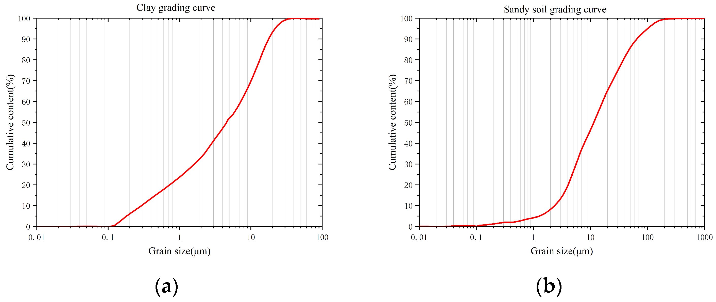
In the offshore environment, the cyclic load caused by waves and currents has a great influence on the long-term performance of skirt–pile foundations. Most of the previous experiments were based on sandy seabeds, and few studies were conducted on clayey seabeds, where most of China’s wind farms are located. In this paper, an experimental study is described on the ultimate bearing performance of skirt–pile foundations under the action of horizontal static load, focusing on the cumulative deformation process and the variation in the foundation bending moment distribution under the action of a long-term horizontal cycle in saturated clay. The structural characteristics and load-sharing mechanism of skirt foundations can be deeply understood by exploring skirt size changes. Then, the influence of skirt–pile foundations on the bearing performance and deformation resistance of composite foundations can be further explored. The identification of the potential mechanisms of foundation degradation by analyzing the cumulative deformation of foundations under cyclic loads is critical to predicting long-term foundation performance.
3. Results
In this section, the deformation and internal force development of different pile types at a steady state are investigated by analyzing the results of model test data to examine the horizontal static failure load of the skirt–pile foundation.
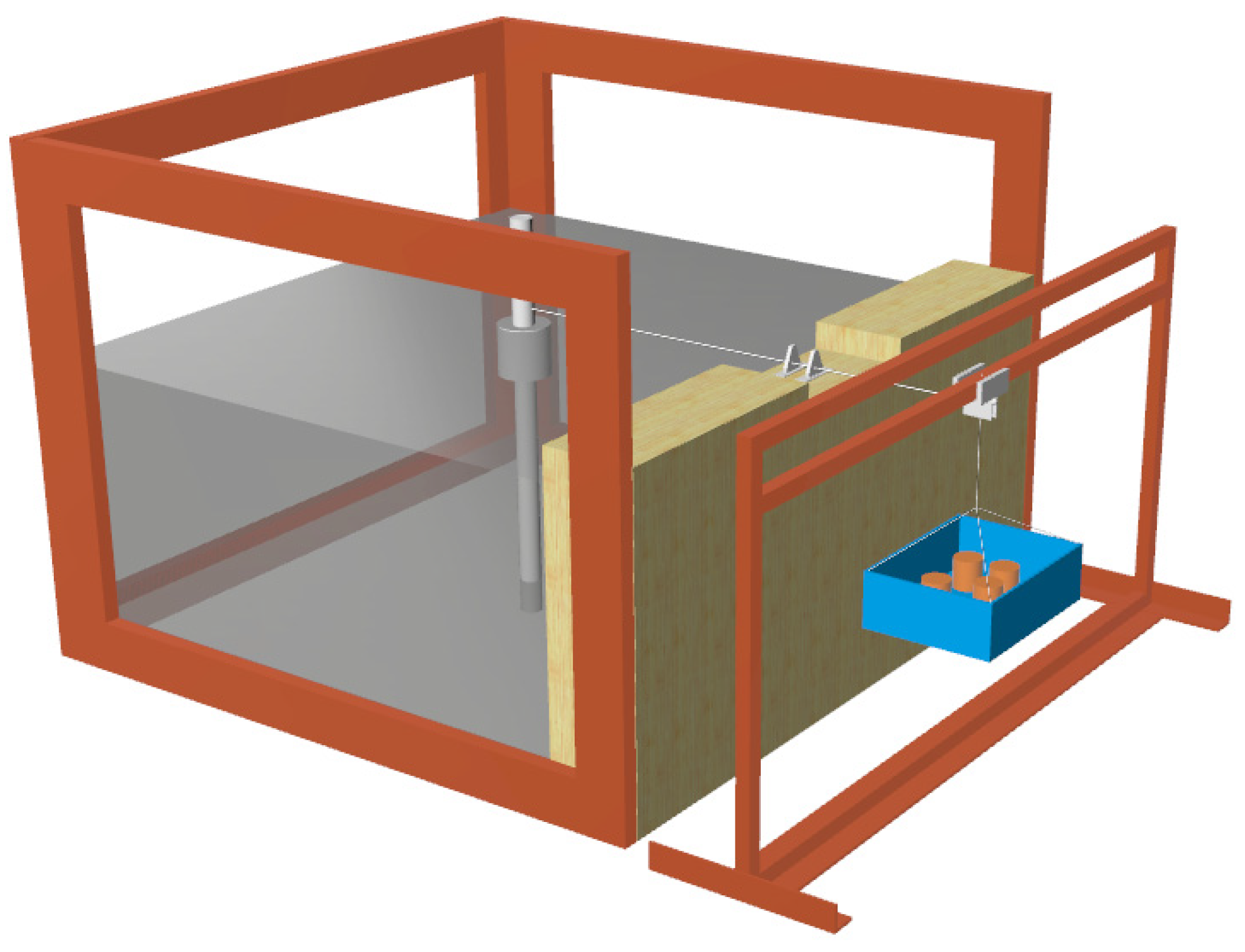
The primary focus of this study is to examine the horizontal ultimate bearing capacity of the skirt–piles and the force–deformation behavior of the skirt–piles under both horizontal static loading and cyclic loading conditions through horizontal static loading tests. The horizontal static loading system primarily consists of components such as steel wire rope, a fixed pulley, weights, a weight plate, a steel frame, and other structures, and the details of the loading device can be observed in
Figure 5. The testing system connects the weight plate with the model pile through the fixed pulley using the wire rope. During the loading process, the system gradually places weights on the weight plate, thus converting the vertical self-weight of the system into a horizontal load applied on the pile. It is important to note that friction between the wire rope and the fixed pulley is ignored during the loading process. By conducting these tests, the force deformation law of the skirt–pile can be determined under different loading conditions.
The horizontal static force was applied to the pile foundation by the slow maintenance load method, and a constant step loading increment of 15 N was adopted. The horizontal static force test curves of different sizes of skirt–piles and monopiles were obtained.
Figure 6 and
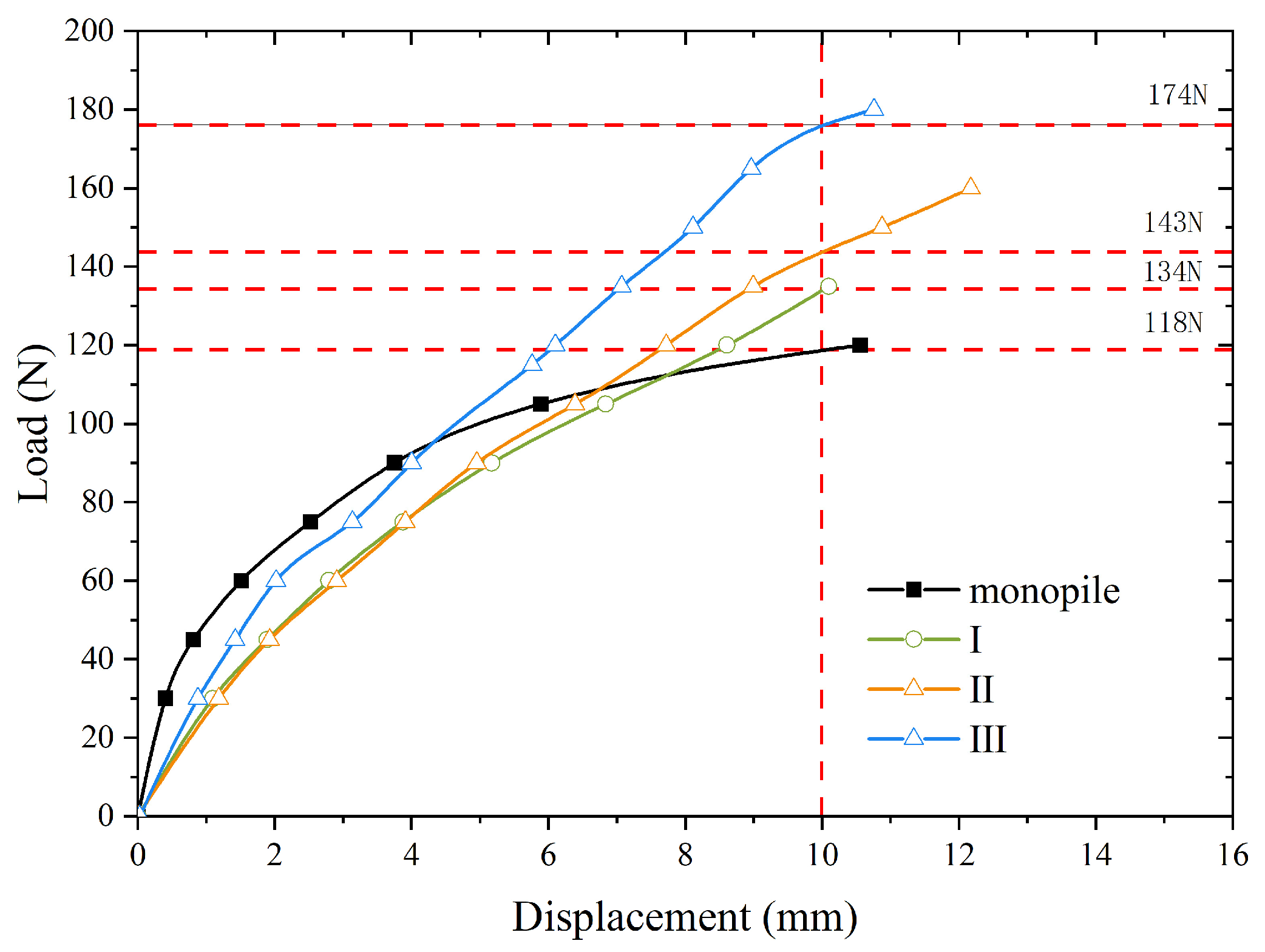
Figure 7 present the outcomes of the static testing, with the load–deflection curves showcased in
Figure 6. It is evident that the inflection point of the load–displacement curve is not apparent for skirt–piles I, II, and III. Thus, the criterion put out by Broms [
39] is used to assess the piles’ ultimate horizontal bearing capability, which assumes that the ultimate state of the small-diameter driven pile occurs at 20% of the pile diameter. The load equal to the displacement at 0.2 d (10 mm) in the figure can be used to determine the pile’s ultimate bearing capacity. The horizontal ultimate bearing capacities of the monopile and skirt–piles I, II, and III in pack and clay are 118 N, 134 N, 143 N, and 174 N, respectively. Evidently, the skirt–pile foundations exhibit a higher horizontal ultimate bearing capacity compared to the monopile foundation, and the three skirt–piles increased the horizontal ultimate bearing capacity by 13.6%, 21.2%, and 47.5% compared to the monopile foundation. This can be attributed to the added skirt acting like a barrel foundation, which can limit the horizontal displacement to a great extent. Furthermore, increasing the diameter of the skirt enhances the load-bearing performance of the foundation more effectively than deepening the skirt.
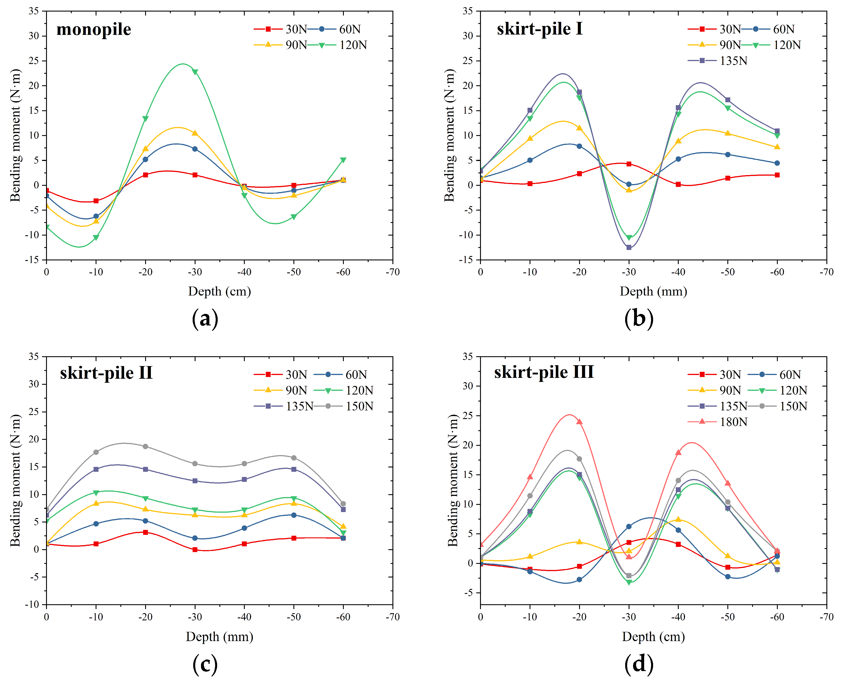
Figure 7 presents the bending moments of the different pile types under various loading conditions. The following image shows that the model pile’s damage mode is near the development of plastic hinges; as a result, the model pile may be described as flexible.
The bending moment increases proportionally with the amplitude of the applied horizontal load. The skirt effectively redistributes the applied loads, leading to changes in the distribution of the bending moment along the length of the pile. Notably, the maximum bending moment of the monopile is observed at a depth of 30 cm below the soil surface. For skirt–piles I and III, the maximum bending moment first appears at 30–40 cm below the soil surface, and as the load increases, its maximum bending moment point shifts upward to 20 cm. Due to the skirt foundation’s increased soil restriction when the static load acts, the pile’s bending moment reverses at the same instant. The presence of the skirt alters the interaction between the pile foundation and the surrounding soil. The skirt influences the distribution of soil pressures and shear forces exerted on the pile shaft. With the gradual inclination of the pile, there was a compressive effect on the soil inside the skirt, which changed the internal force of the pile. Interestingly, compared to skirt–piles I and III, the overall increase in the pile bending moment of skirt–pile II with the increase in load is considered to be the larger length/diameter ratio of the skirt foundation, which increases the overall stiffness of the composite pile. The increased stiffness aids in resisting lateral bending and deformation, which in turn affects the distribution of bending moments within the foundation.
4. Discussion
In this section, the variations in accumulative deformation and pile bending moment under long-term cyclic loading are further compared and discussed for different skirt diameters and lengths. Subsequently, load–displacement curves are generated based on the measured loads and displacements. Each pile type’s horizontal cyclic stiffness development is thoroughly examined, with a focus on the load–displacement relationship.
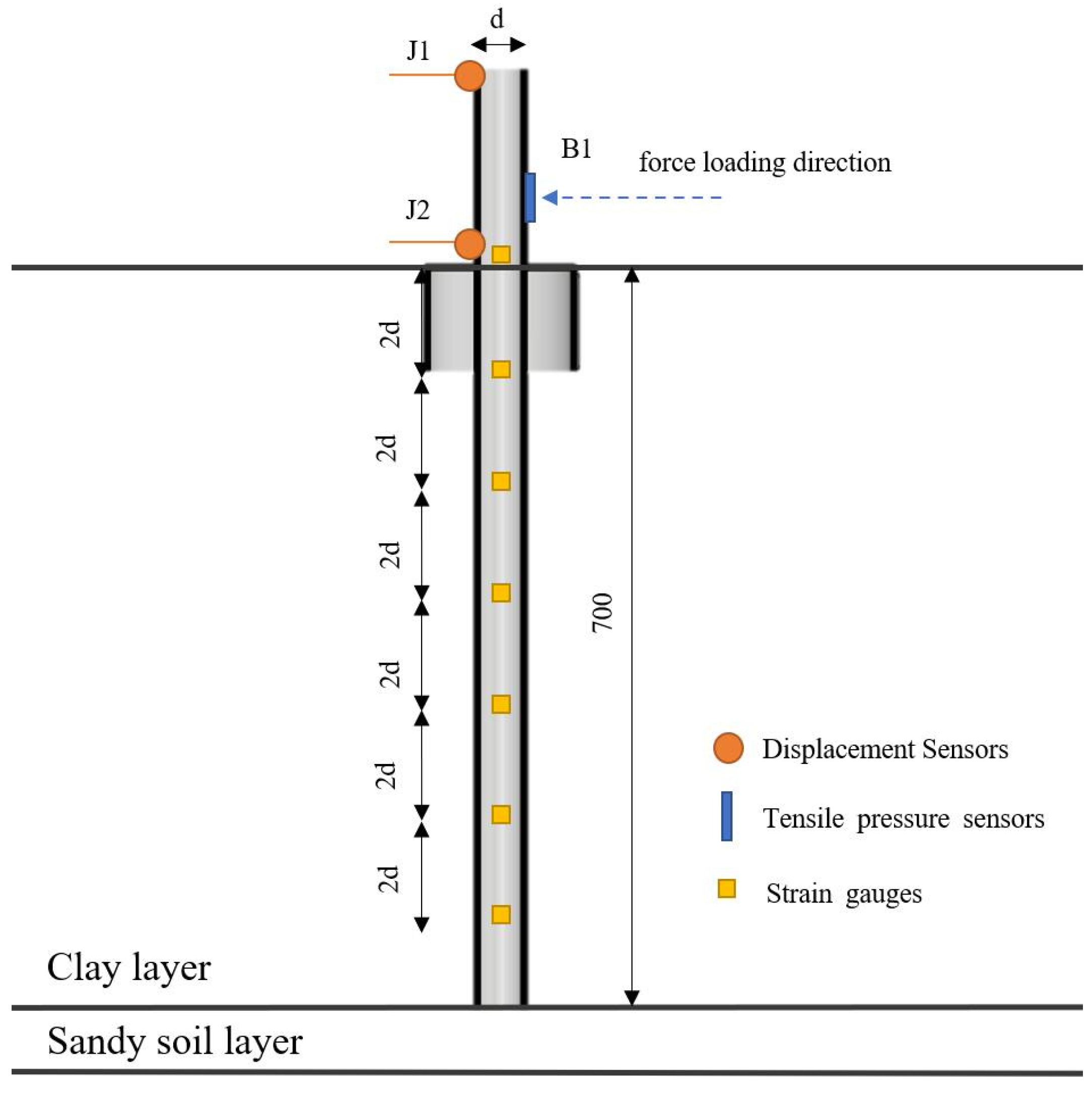
We examined the skirt–pile foundation’s accumulated deformation by examining the rotational change. Displacement meters were installed at the top of the pile and at the mud surface along the loading direction to measure the pile turning angle under the influence of horizontal cyclic loads. The horizontal displacement at the corresponding position was measured, and the pile rotation could be obtained by calculating the horizontal displacement difference using the vertical spacing of the two displacement meters. The cumulative angle of rotation can be calculated using Equation (1).
where
is the rotation of the pile,
is the vertical distance of two displacement meters (J1 and J2), and
is the horizontal distance of J1 and J2.
Strain gauges were strategically placed along the pile body to measure both tensile and compressive strains at various elevations. This approach allows for an assessment of the variation in the pile bending moment along the burial depth under long-term cyclic loading, employing the elastic foundation beam theory. Then, the pile bending moment is calculated by Equations (2) and (3):
where
is the moment of inertia of the pile section;
is the modulus of elasticity of the pile foundation, taking the value of 71 Gpa;
is the pile bending moment; and
and
are the tensile and compressive strains on both sides of the pile base, respectively.
4.1. Effect of the Skirt Length
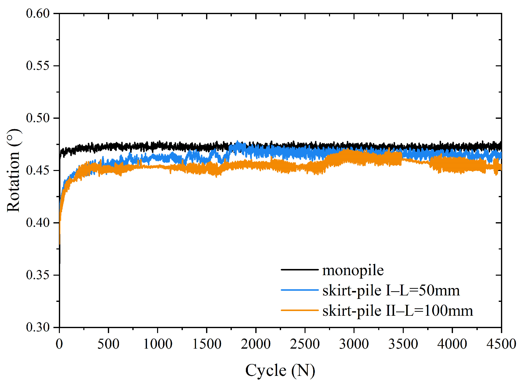
Figure 8 (
denotes the pile rotation, and N denotes the number of cycles) shows the comparison of the cumulative rotations of the monopile and skirt–piles I and II, and then analyzes the effect of different skirt lengths on the resistance to deformation. Three stages may be distinguished in the cumulative process of the model pile’s rotation as the number of cycles increases. The model pile displays cumulative deformation characteristics under horizontal cyclic loading in saturated clay soil.
The first stage is the rapid development stage, occurring within the first 100 cycles. In this phase, the cumulative rotation of the pile experiences a rapid increase with the progression of cycle numbers. The second stage is the slow development stage, which occurs between 100 and 500 cycles for the monopile, between 100 and 2000 cycles for skirt–pile I, and between 100 and 4000 cycles for skirt–pile II. In this stage, the cumulative rotation of the model pile grows gradually and slowly, and the slowdown trend increases continuously. The cumulative rotation of the monopile rapidly reaches equilibrium compared to skirt–piles, indicating that as the skirt length increases, the resistance to deformation increases. An interesting finding was that increasing the skirt length significantly increased the duration of the slow development stage, making it slower to reach equilibrium. After the end of the second stage, the stable development stage is entered. With the increase in cycle times, the cumulative rotation of the pile ceases to increase and tends to be stable. Similar observations have been made in previous studies conducted on loose dry sand [
37] and dense saturated sandy soils [
38]. At N = 300 cycles, the cumulative rotation of skirt–piles I and II are 0.455 and 0.45, respectively. At N = 4500 cycles, the corresponding values are 0.463 and 0.45, respectively. This phenomenon illustrates that the advantage of increasing the skirt length to resist the horizontal deformation of model piles under long-term cyclic loading is more obvious.
The primary cause of the cumulative deformation of the model pile is the reshaping of the surrounding soil under horizontal cyclic loading. In the early stage of loading, rapid movement of soil particles occurs under horizontal cyclic loading, inducing a transformation in the original arrangement. The continuous rearrangement of soil particles and alterations in the soil skeleton contribute to the escalating cumulative deformation of the pile. With the increasing number of cycles, after the rapid development stage, the movement between soil grains weakens, the arrangement of soil grains re-enters the stable state, and the resistance to deformation of the soil around the pile increases, but the cumulative rotation angle of the pile continues to grow slowly. The soil particles essentially stop moving in the late stage of cyclic loading; at this time, the cumulative rotation of the pile enters the stable stage.
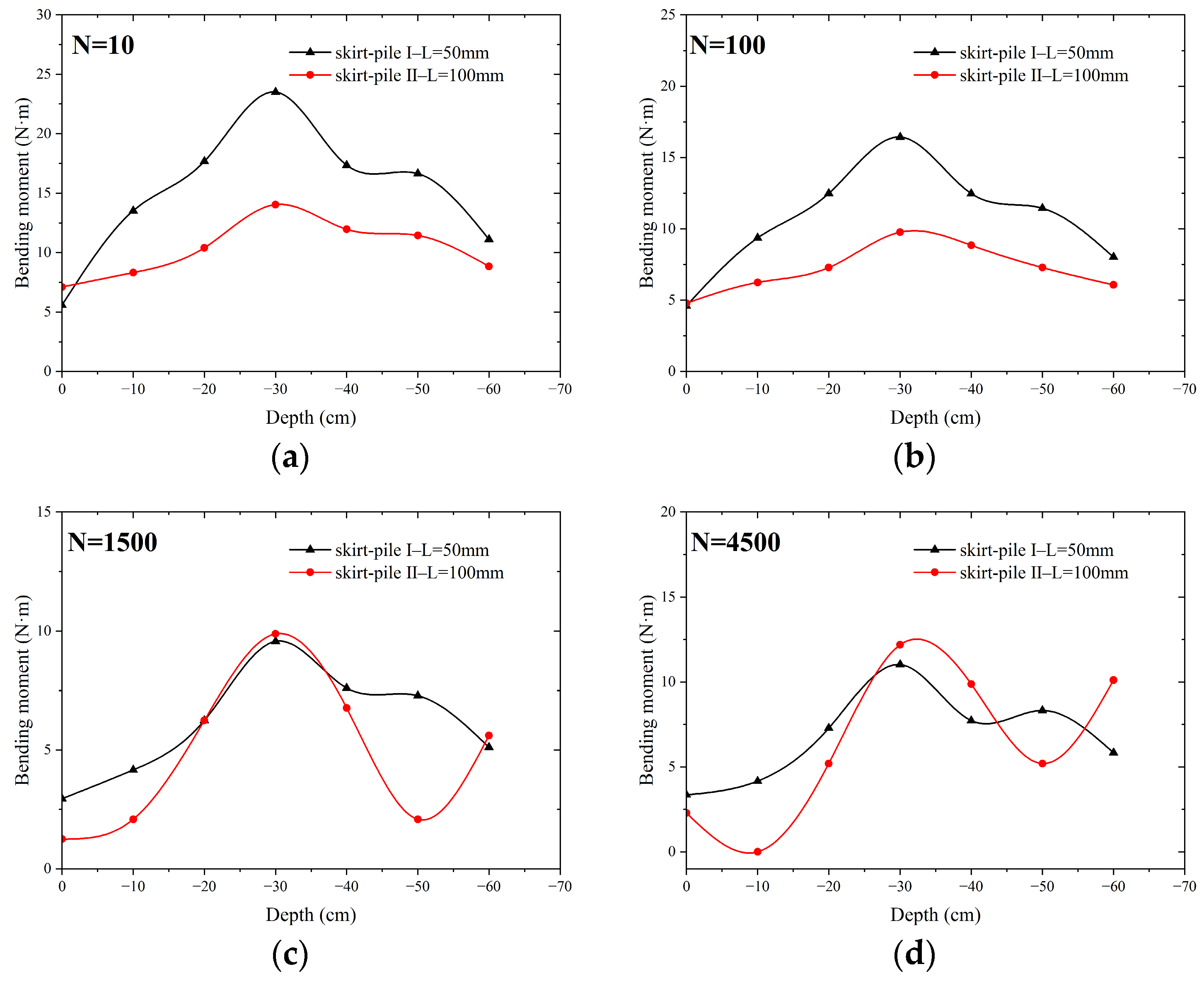
According to the previous analysis, the cyclic accumulation process is divided into three stages. Thus, the pile bending moment at each stage is selected for comparative analysis at the characteristic moment (N = 10, N = 100, N = 1500, N = 4500).
Figure 9 demonstrates that the maximum bending moment of skirt–piles I and II occurs at 30 cm below the mud surface. Before reaching 1500 cycles, skirt–pile I exhibits a higher maximum bending moment compared to skirt–pile II. However, as stability is achieved beyond 1500 cycles, there is a discernible shift, with the maximum bending moment of skirt–pile II progressively surpassing that of skirt–pile I.
The maximum bending moment of the pile produces a large reduction in the first stage, i.e., the rapid development stage, indicating that during this process, the rapid softening of the soil occurs. When the cyclic load develops to the second stage (N = 1500 cycles), the reduction gradually decreases to zero as the number of cycles increases, which means that the pile bending moment is stable at this stage, indicating that the rate of soil softening at this stage is unchanged. As the cyclic load advances into the third stage (N = 4500 cycles), the bending moment of the pile shows a consistent increase with the number of cycles. This suggests that the soil surrounding the pile undergoes a rearrangement of particles after softening during each cycle, ultimately forming a new equilibrium. With the increase in cycle times, the bending moment of skirt–pile II appeared at 10 cm and 50 cm below the mud surface, which indicates that the growth of the skirt length could effectively share the bending moment of the monopile under long-term cyclic loading.
4.2. Effect of the Skirt Diameter
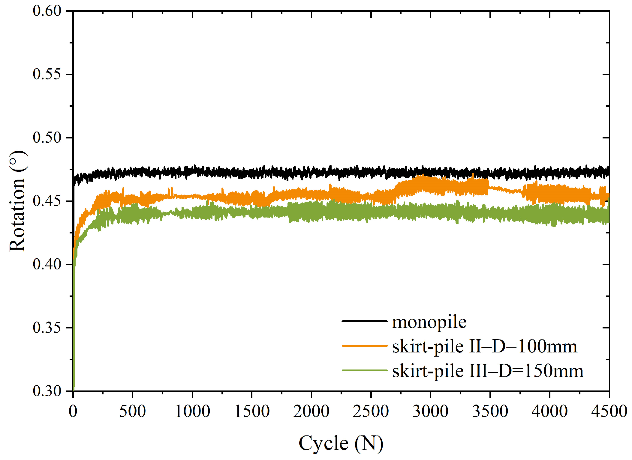
Figure 10 compares the cumulative rotation of different skirt diameters (skirt–piles II and III), showing the varying resistance to deformation. The development of cumulative rotations in skirt–pile III is also categorized into three stages. The first stage occurs within the initial 100 cycles, the second stage spans from 100 to 1500 cycles, and the third stage takes place between 1500 and 4500 cycles.
As can be seen from
Figure 10, as the skirt radius increases, the cumulative rotation of the skirt–pile composite foundation decreases throughout the cycle. And it was found that the second stage of skirt–pile III was a shorter process compared to skirt–pile II and reached equilibrium faster. The cumulative rotation of skirt–piles II and III are 0.53 and 0.45 at N = 4500 cycles, indicating that the increased radius of the skirt further increases its resistance to deformation. The larger skirt diameter provides more lateral support for the foundation, making it more resistant to horizontal movement or deformation. In addition, the increased bearing area of the skirt helps to disperse the lateral load, reducing the stress placed on the soil and minimizing the possibility of soil damage or excessive settlement. Therefore, increasing the skirt diameter usually improves the deformation resistance of the skirt–pile foundation, making it better able to withstand lateral forces and maintain stability. Analyzed in conjunction with
Figure 8, increasing the skirt length reduces the cumulative corner on the one hand, and on the other hand allows its corner development process to enter the stabilization stage earlier. However, increasing the skirt diameter only reduces the cumulative rotation angle, and the development trends of skirt–piles II and III are the same.
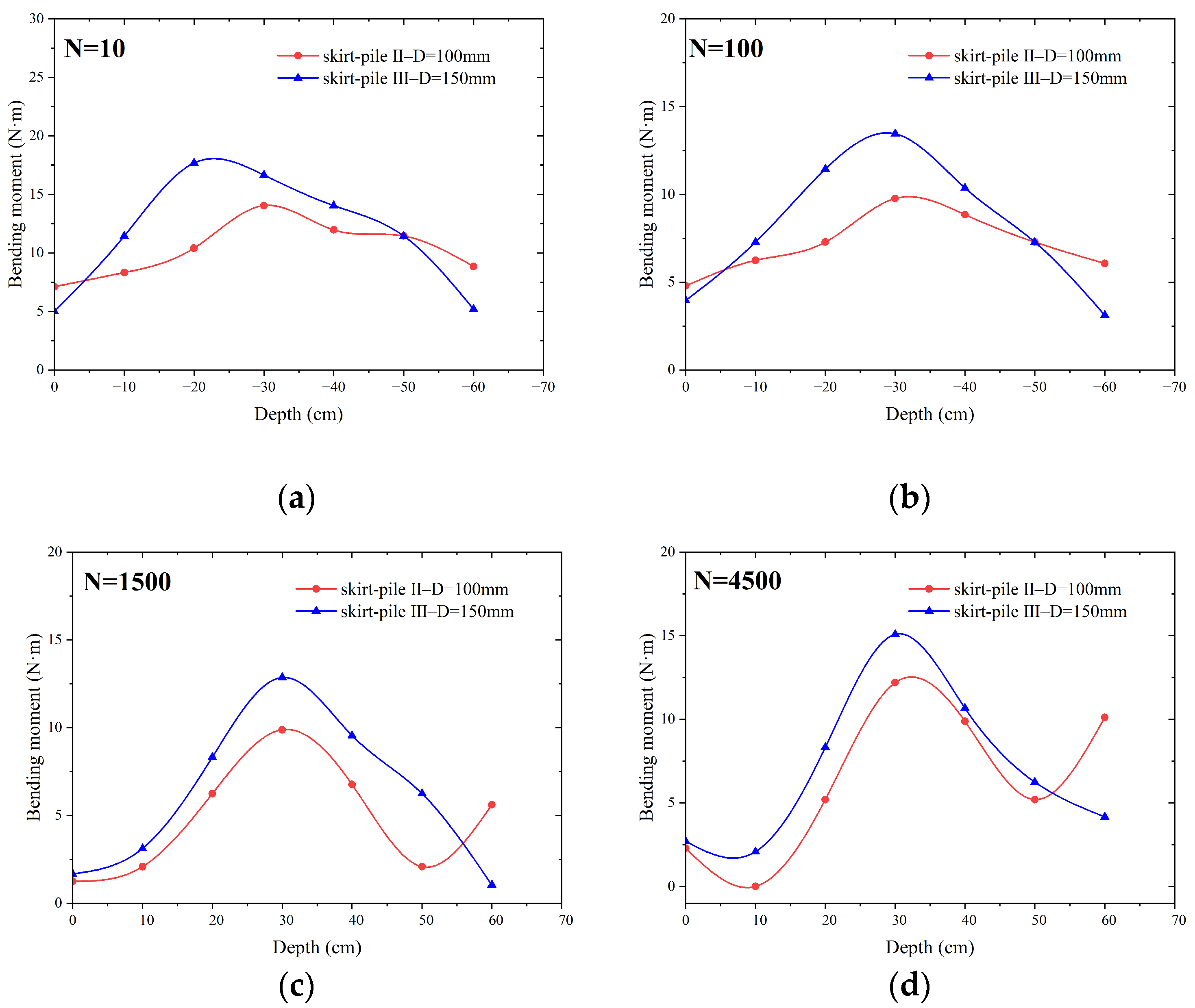
Figure 11 compares the bending moments of skirt–piles II and III for different cyclic load cycles (N = 10, N = 100, N = 1500, N = 4500) to study the effect of skirt diameter on the internal force of the pile under cyclic loading. The maximum bending moment point of skirt–pile III appears 20 cm below the mud surface at the beginning of cyclic load loading, and the maximum moment point shifts down with the increase in the cyclic number and stabilizes 30 cm below the mud surface. For skirt–pile III, in the first stage (N = 10–100 cycles), the soil softens rapidly and the pile bending moment decreases sharply. During the second stage of cyclic loading (N = 100–1500 cycles), the bending moment gradually decreases and stabilizes as the number of cycles increases. During this stage, the softening rate of the soil remains constant. As the cyclic loading progresses to the third stage (N = 1500–4500 cycles), the bending moment of the pile increases in correlation with the number of cycles, signifying a soil rearrangement that leads to a new equilibrium state during the cyclic process. The whole development processes are consistent with skirt–pile II.
The bending moment progression of skirt–pile III along the pile’s depth direction closely resembles that of skirt–pile II. In the initial loading stage, the bending moment rises and subsequently decreases with increasing depth. After a specific loading duration, back-bending points emerge at depths of 20 cm and 60 cm below the mud surface. Notably, augmenting the skirt diameter has a more negligible impact on the pile moment shape compared to extending the skirt length.
The influence of the skirt length and skirt diameter on the ultimate bearing capacity and deformation resistance was quantified. These parameters can be optimized in practical engineering to meet specific project requirements and environmental conditions. By determining the most effective combination of these parameters, the desired level of performance can be achieved while minimizing material use and construction costs.
4.3. Cyclic Stiffness Degradation
Saturated clay soils with installed pile foundations are susceptible to softening under cyclic loading, which can result in plastic deformation of the soil and the pile–soil system [
40,
41]. This softening and plastic deformation can significantly affect the performance of the foundation, potentially leading to structural damage or failure. To gain a deeper insight into the pile–soil system’s response to cyclic loading, it is crucial to analyze its cumulative cyclic properties alongside its load–deflection behavior. The cyclic stiffness of the pile–soil system pertains to its capacity to resist deformation and sustain its load-bearing capacity under cyclic loading conditions. This property can be measured by conducting cyclic loading tests on the pile–soil system and analyzing the resulting load–deflection curves.
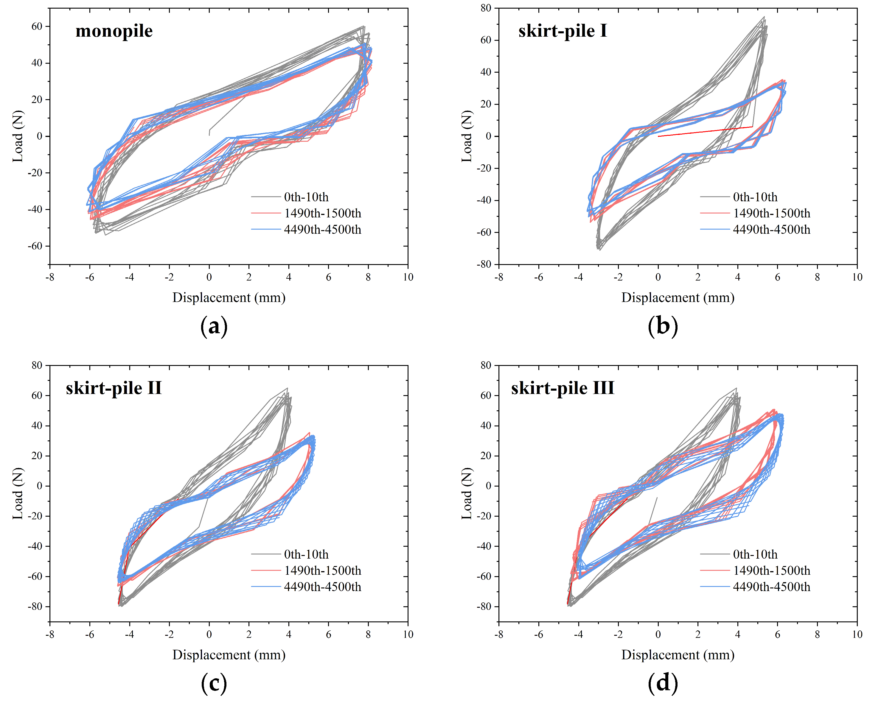
The normalized load–deflection curves are presented in
Figure 12. To enhance clarity and facilitate visualization, the rapidly developing stage, slowly developing stage, and steadily developing stage are separated into three sets of load–displacement curves. These three sets correspond to the 1st to 10th cycles, the 1490th to 1500th cycles, and the 4490th to 4500th cycles, respectively. As depicted in
Figure 12, the hysteresis curves of the pile–soil system under cyclic loading showcase both translational and rotational movements. These phenomena signify the occurrence of plastic deformation and stiffness degradation in the system as the number of cyclic loads increases.
To provide a more comprehensive analysis of the cumulative deformation patterns of skirt–piles under horizontal cyclic loading, this section evaluates the deformation by examining foundation stiffness. The cyclic stiffness is calculated by dividing the load amplitude by the displacement amplitude of the pile foundation in each cycle [
42]. The calculation formula for cyclic stiffness is Equation (4):
where
is the cyclic stiffness,
is the horizontal cyclic load amplitude, and
and
are the maximum and minimum values of horizon cyclic displacement, respectively.
This study investigates the variation in cyclic stiffness to gain insights into the evolution of horizontal cyclic stiffness in pile foundations in relation to the number of loading cycles.
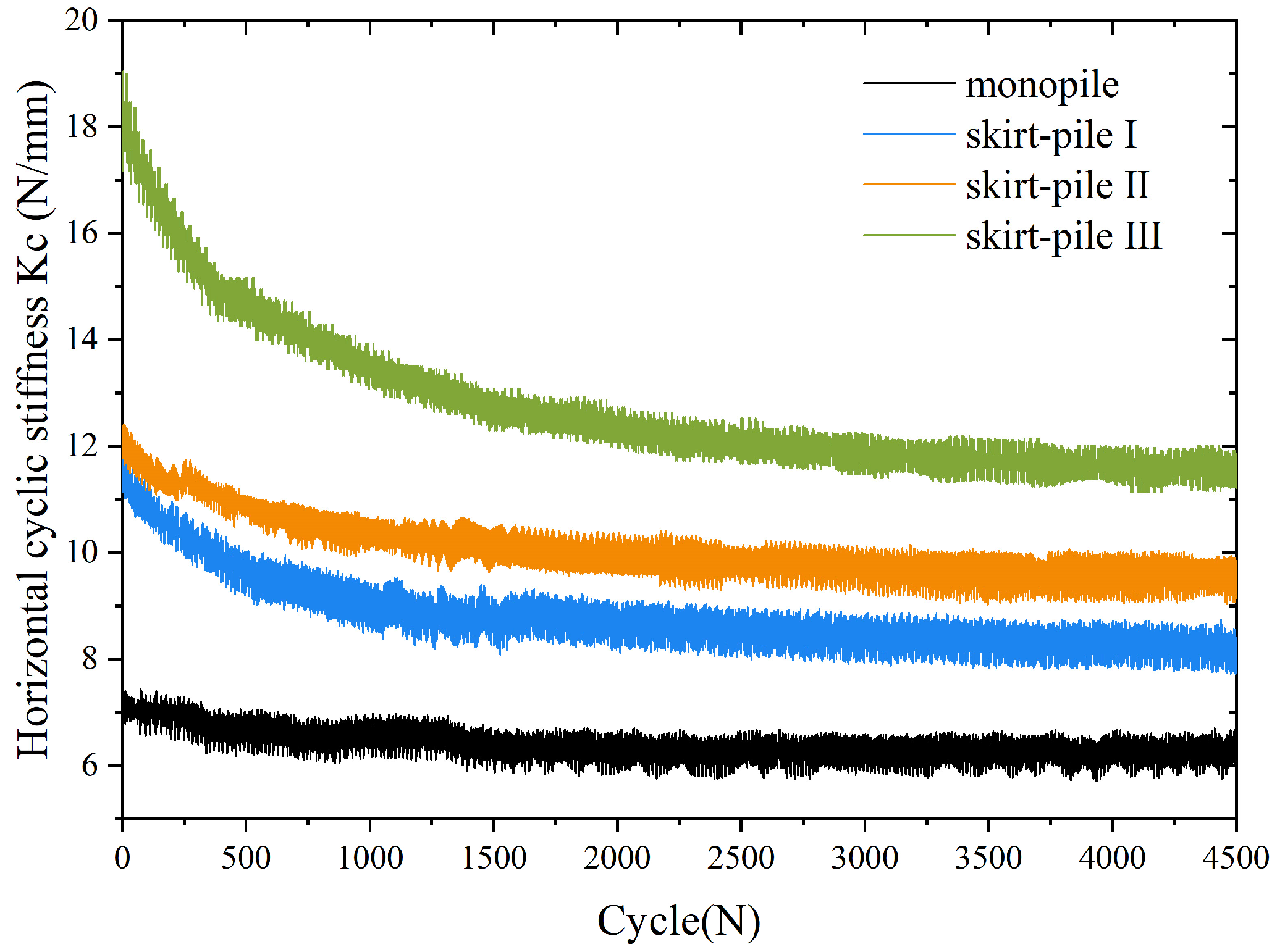
The results illustrated in
Figure 13 reveal a consistent decline in the horizontal cyclic stiffness of the monopile as the number of loading cycles increases. Moreover, the discrepancy between the maximum and minimum load values in the Nth loading cycle consistently decreases with the growing number of cycles. This trend corresponds to an increasing strain level in the soil and a continuous reduction in plastic deformation. These observations suggest that the accumulated deformation tends to stabilize with the increase in the number of cycles. The skirt–pile seat undergoes rapid degradation during the initial loading process but tends to stabilize with increasing loading cycles. In terms of overall stiffness, it was found that III > II > I > monopile. This implies that as the skirt size increases, its cyclic stiffness becomes greater and its resistance to deformation becomes stronger, which is the same as the conclusion drawn from the cumulative turning angle. At N = 3000, the cutline stiffness variation tends to stabilize, indicating a balance between the softening effect of remodeling and the stiffness effect of reconsolidation. Analyzing the potential mechanisms of foundation degradation can provide a theoretical basis for accurately predicting the long-term behavior and performance of foundations in practical engineering. By formulating corresponding effective mitigation measures, it ensures their durability, reliability, and safety.
5. Conclusions
In this study, physical model tests were performed to scrutinize the mechanical behavior of skirt–pile foundations under horizontal loads, and the characteristics of the ultimate bearing capacity, cumulative deformation, bending moment, and cyclic stiffness were investigated. Derived from the experimental results, the following conclusions can be drawn:
Enlarging the skirt diameter can greatly enhance the load-bearing capacity of the composite pile, and extending the skirt length can effectively improve the deformation resistance. Optimizing the skirt–pile size achieves desired performance in offshore engineering, minimizing material and construction costs.
In saturated clay soil, the cumulative deformation of the model pile primarily results from the rearrangement of the soil around the pile during horizontal cyclic loading. The cumulative rotation of the pile can be categorized into rapid development, slow development, and stable development stages, providing aid in the design and evaluation of pile foundations in clay.
Throughout the cyclic loading process, the bending moment of the pile initially experiences a decrease followed by an increase. Extending the skirt length is found to be effective in improving the overall stiffness of the skirt–pile, indicating the potential for improving structural integrity and stability through appropriate design modifications.
The horizontal cyclic stiffness increases with an increase in both the skirt length and diameter, and this enhancement is particularly pronounced when increasing the skirt diameter. Meanwhile, the horizontal cyclic stiffness decreases as the number of cycles increases, stabilizing after 3000 cycles. Analyzing foundation degradation mechanisms informs accurate long-term behavior predictions in practical engineering.
This study still carries certain limitations. Assumptions related to soil properties, boundary conditions, or loads may not fully reflect the complexity of the actual offshore environment. Future studies could investigate the effects of additional parameters such as soil properties, water depth, and environmental loading conditions on foundation performance. Additionally, advanced numerical modeling techniques could be employed to simulate the behavior of skirt–pile foundations under more complex loading scenarios.


