
Study on Dynamic Loading Characteristics of Rock Containing Holes


Abstract
1. Introduction
2. Numerical Model
2.1. Experimental Equipment and Data-Processing Methods
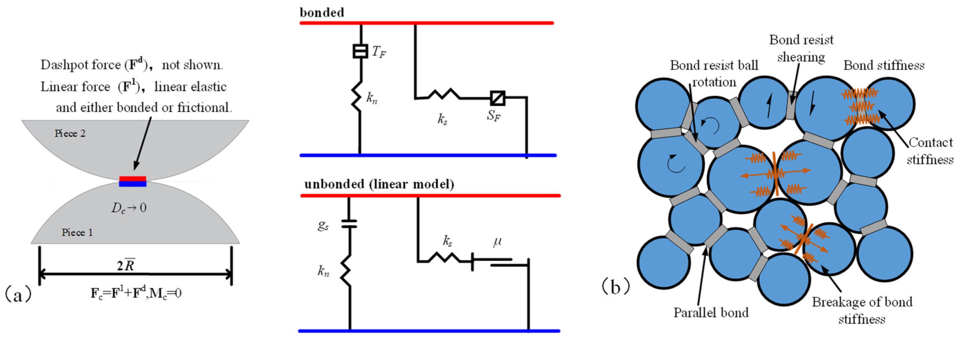
2.2. Introduction to the Discrete Element Method and the Bonded Particle Model
2.3. Numerical Model of the Split Hopkinson Pressure Bar System
2.4. Experimental and Simulation Results Validation and Micro-Parameter Verification
3. Validation of Experimental Results and Reliability of the Numerical Model
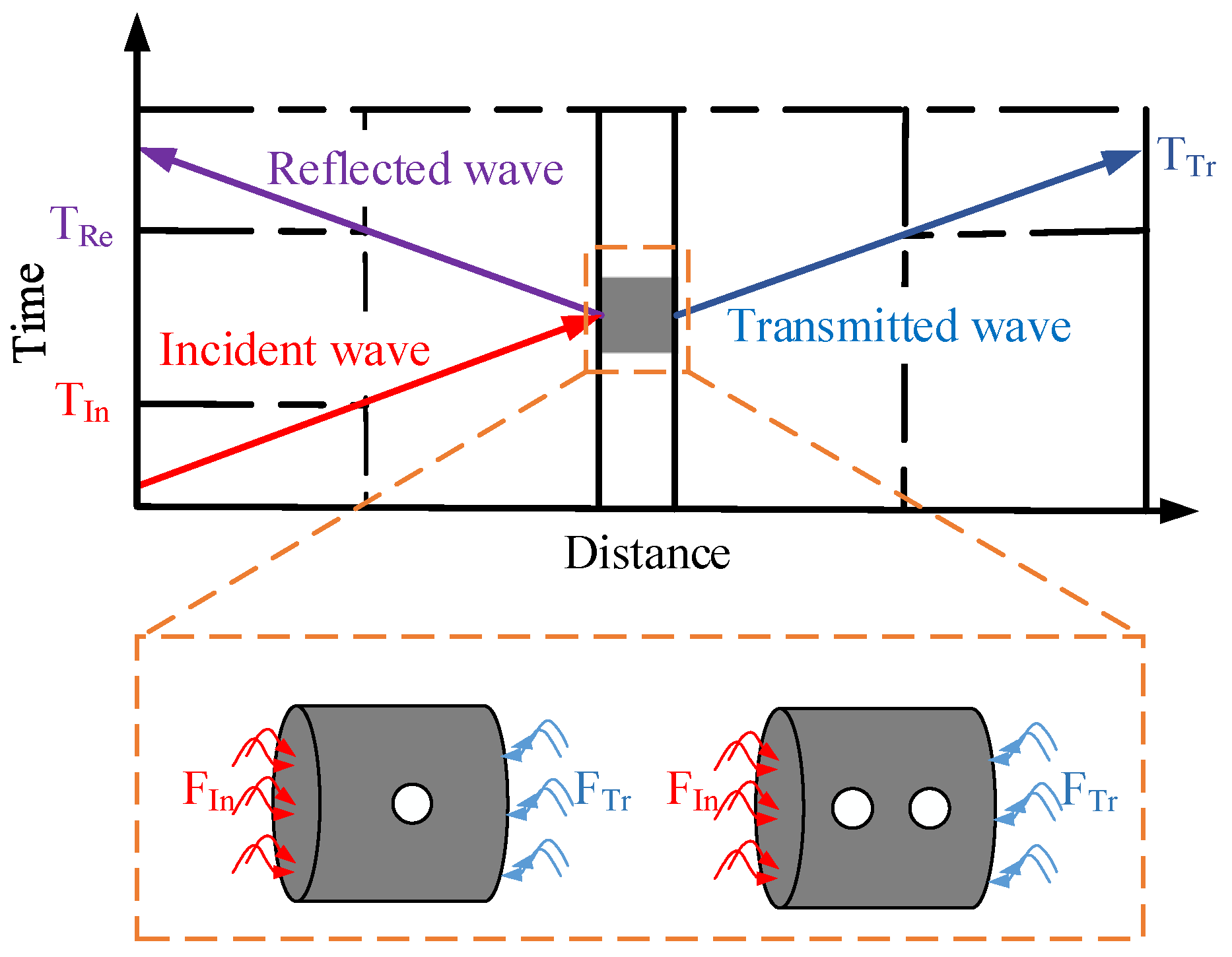
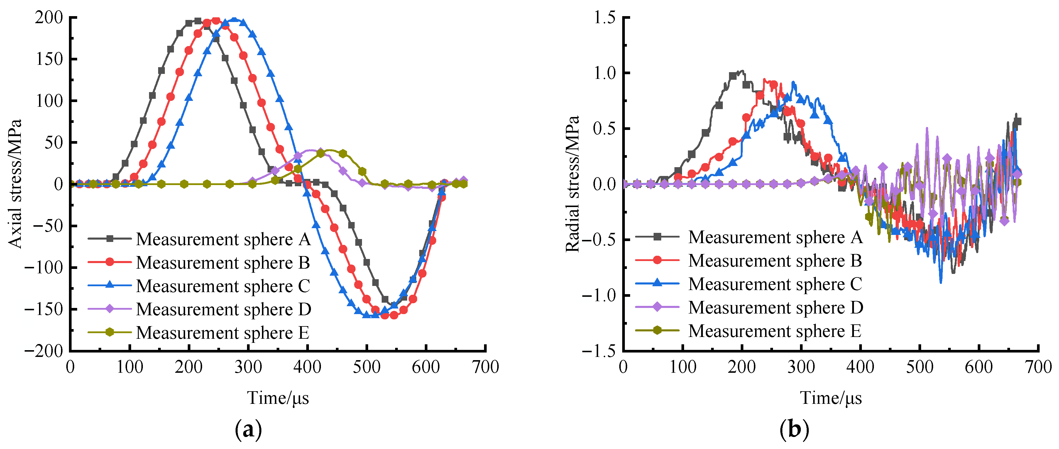
3.1. Propagation of Dynamic Stress Waves
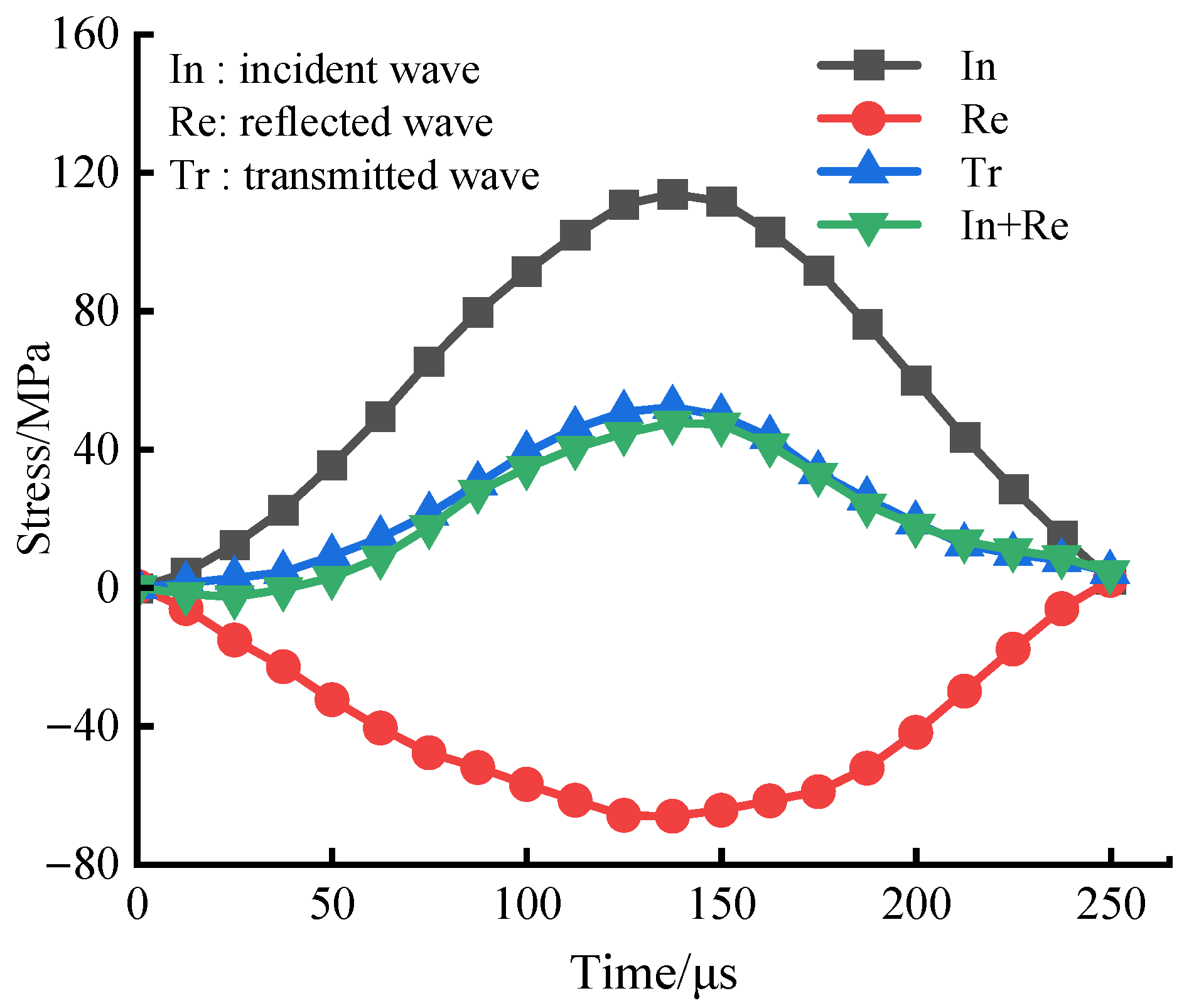
3.2. Verification of Dynamic Stress Equilibrium
4. Simulation Results and Analysis
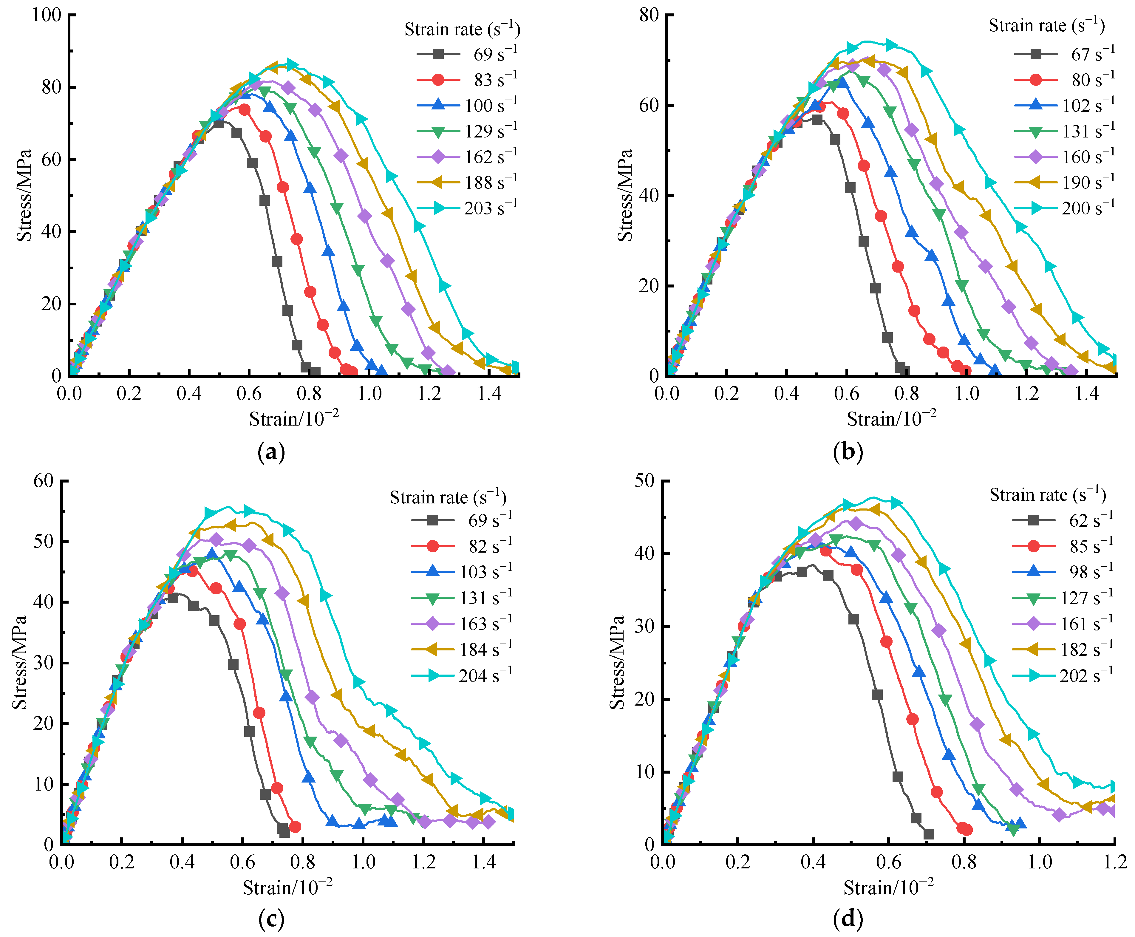
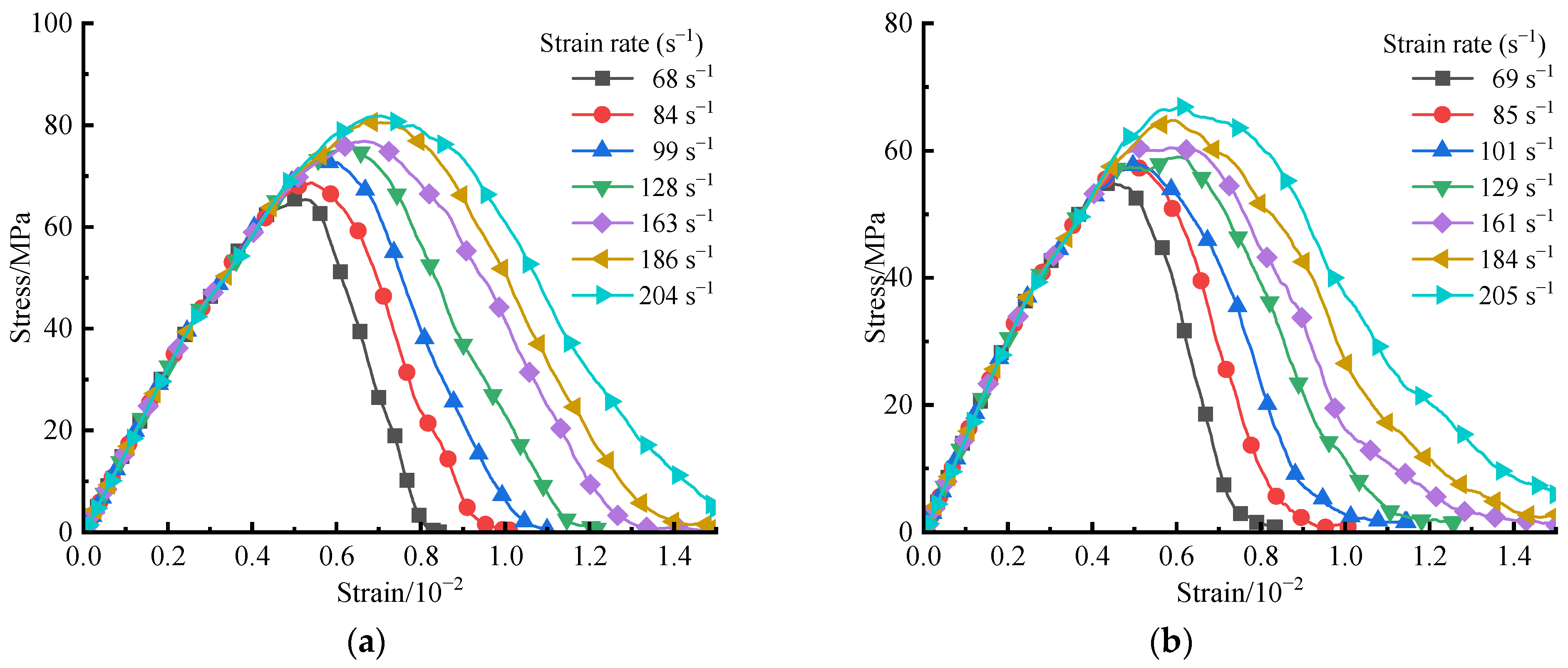
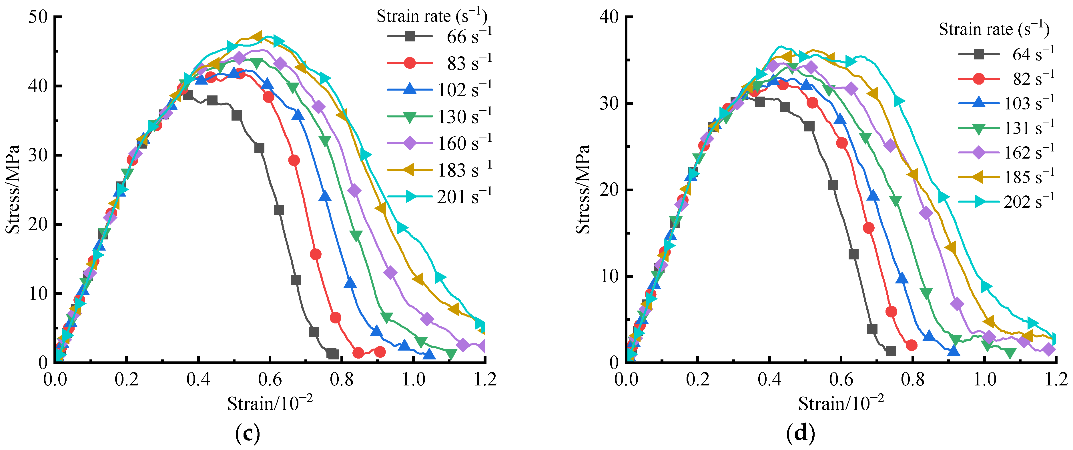
4.1. Simulation Scheme and Stress–Strain Curves
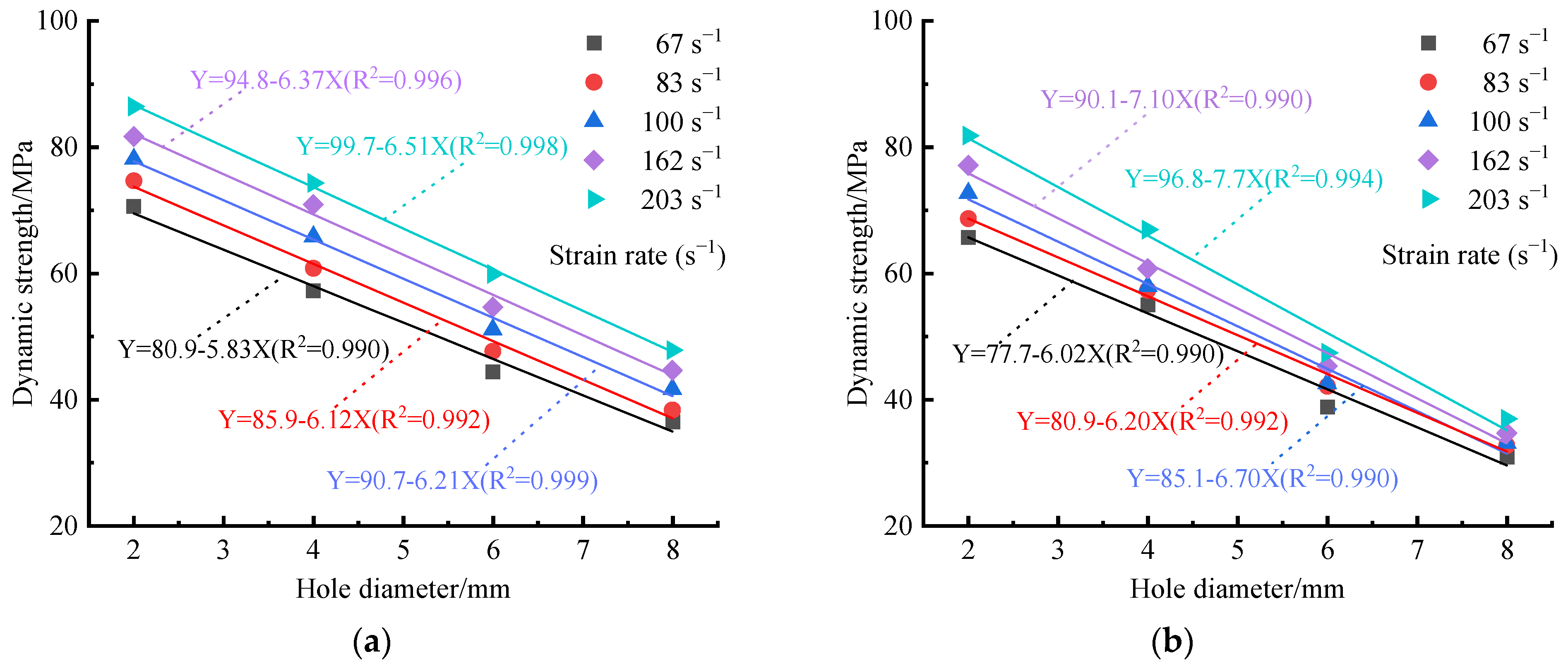
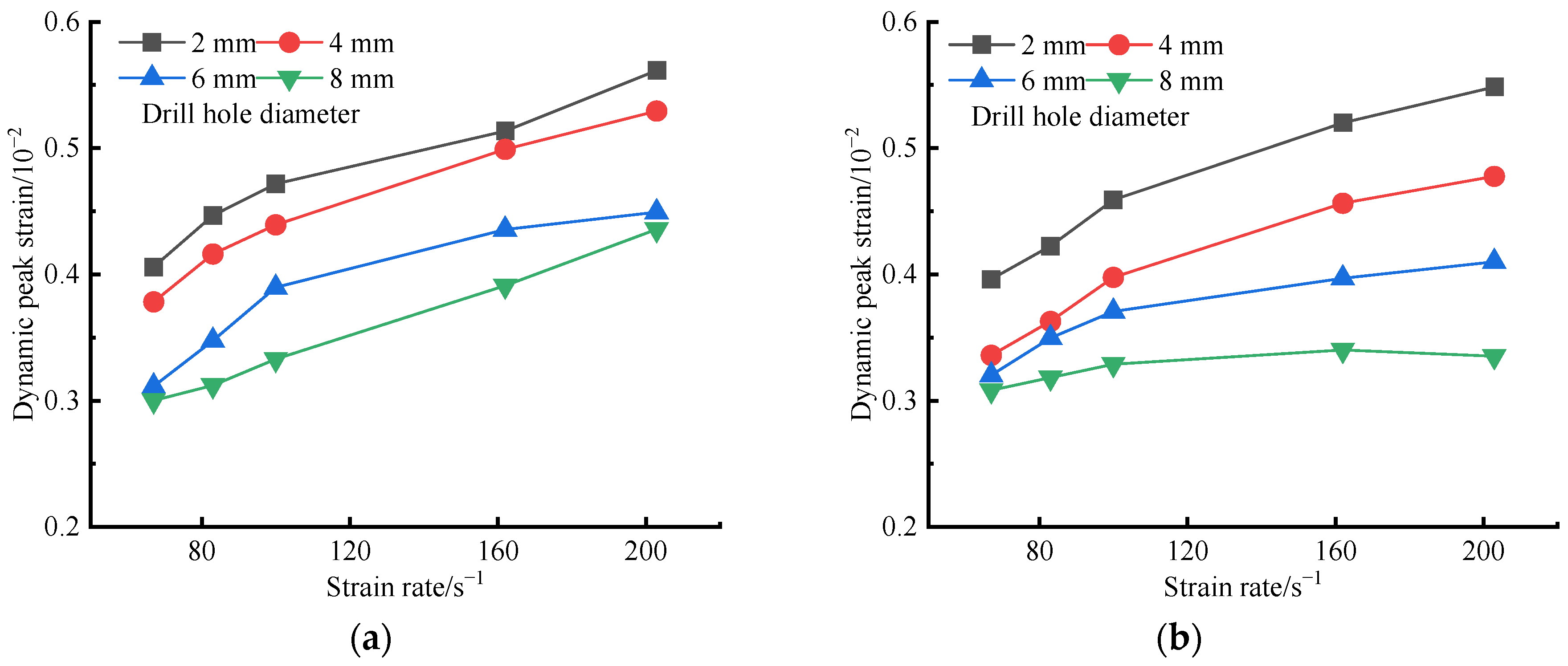
4.2. The Impact of Strain Rate on the Dynamic Mechanical Parameters of Rock Specimens
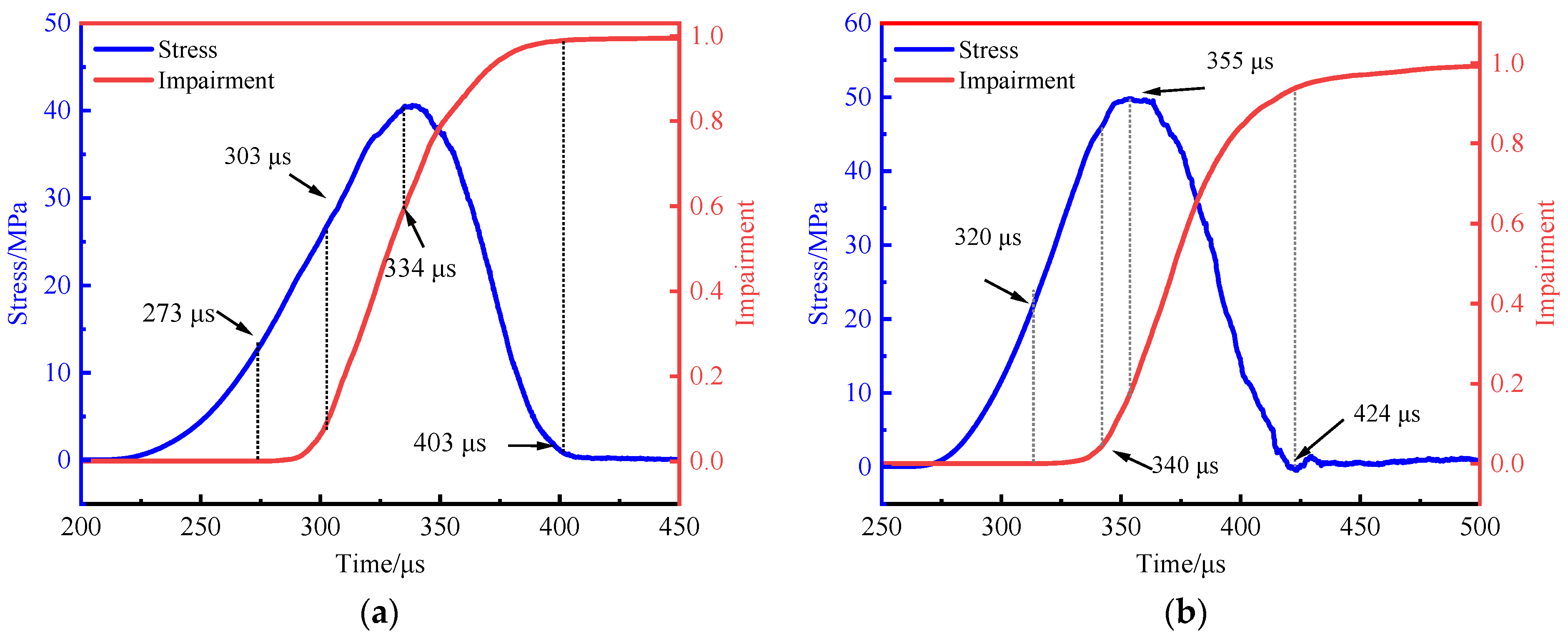
4.3. Failure Behaviours of Specimens with Holes
4.4. Final Failure Modes
5. Discussion
6. Conclusions
- All specimens demonstrated a distinct strain rate dependency, yet the sensitivity of the dynamic mechanical properties of double-hole specimens to strain rate diminished with increasing hole radius. As the strain rate escalated, the growth in dynamic mechanical strength and peak strain for double-hole specimens with larger diameters became less pronounced.
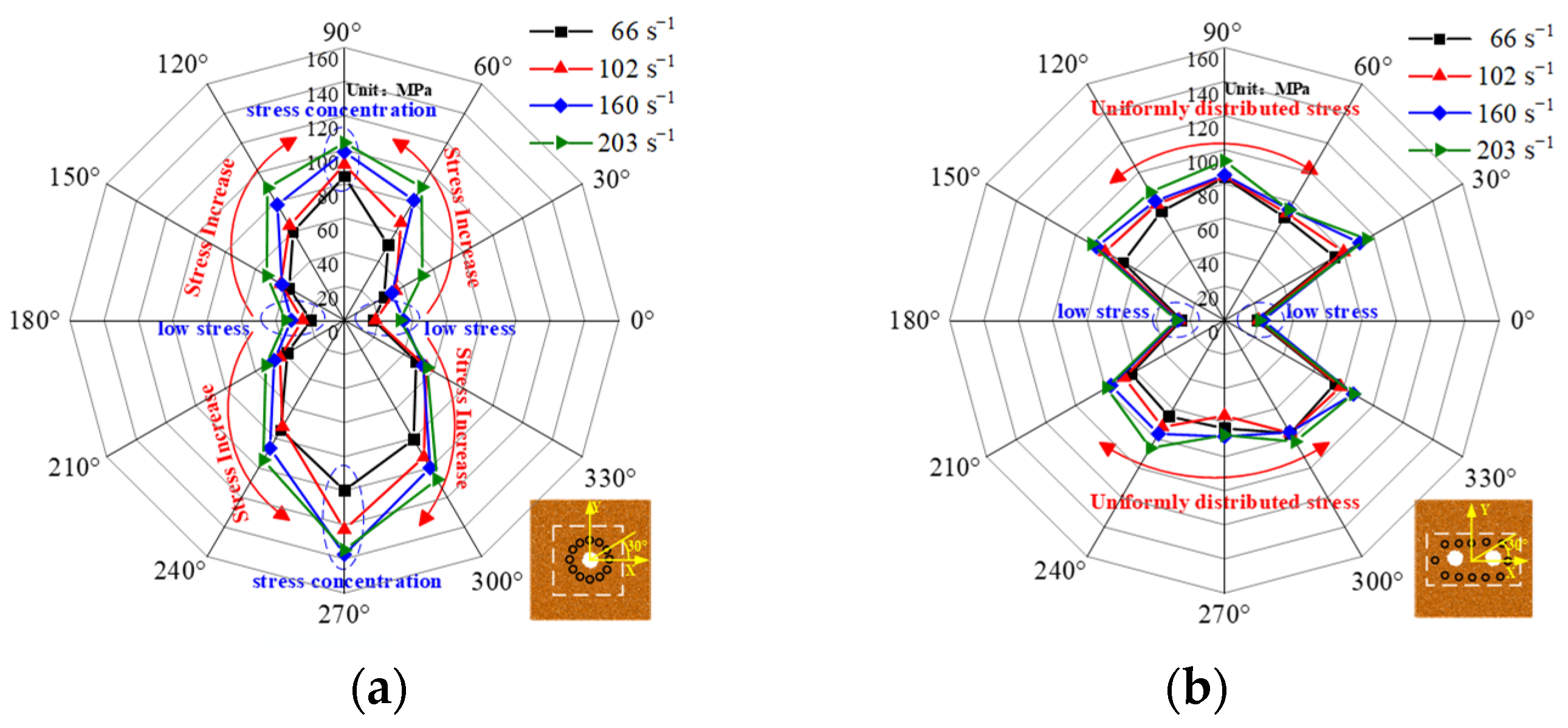
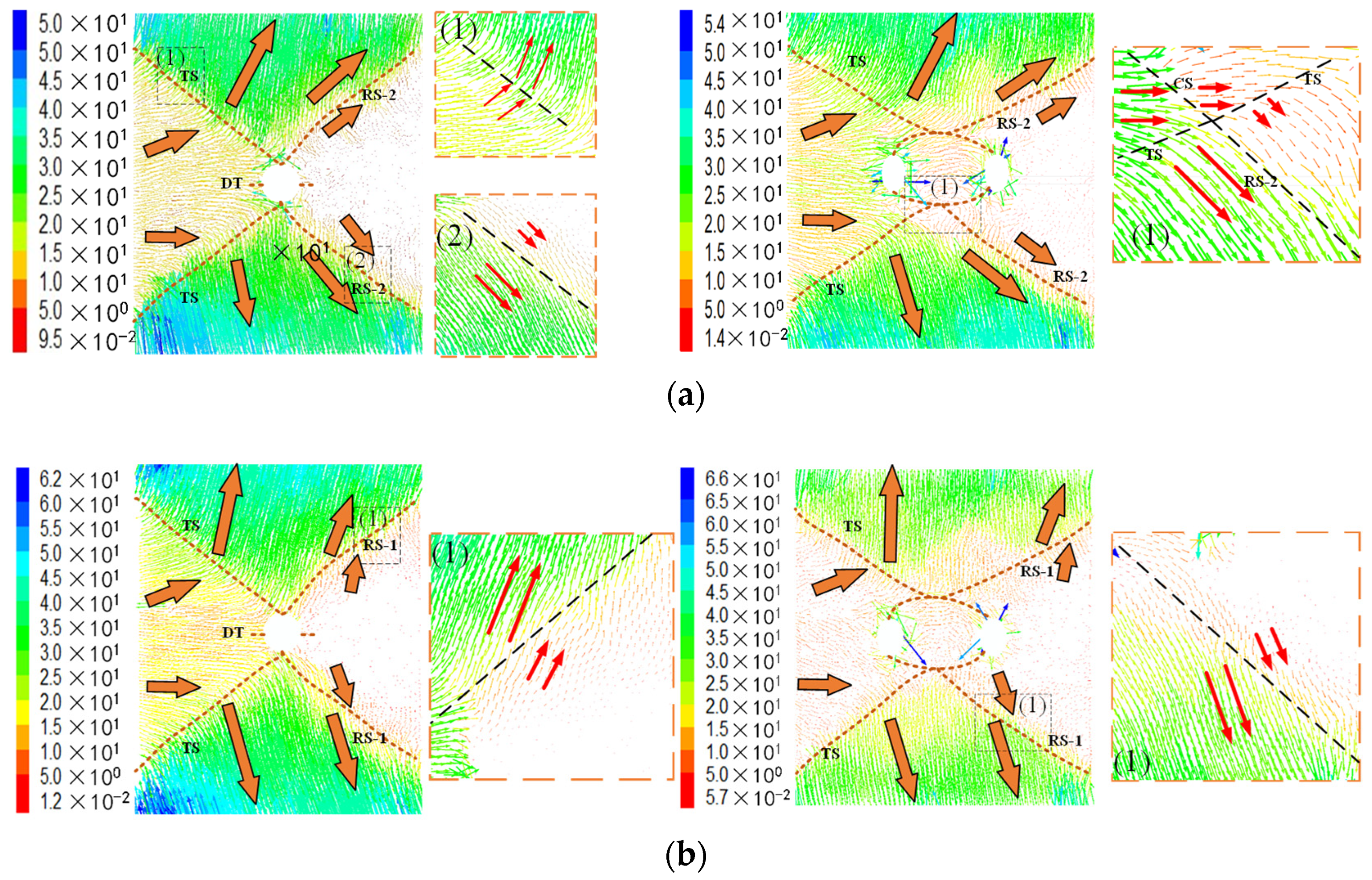
- Upon analyzing the stress field monitoring results for each specimen under varied strain rate loading conditions, a shared trait among all specimens was identified: the emergence of low-stress zones at the axial vertices of the holes, aligned parallel to the loading direction. A key distinction was observed in the stress distribution patterns: single-hole specimens exhibited stress concentration at the radial vertices of the holes, oriented perpendicular to the loading direction. In contrast, double-hole specimens demonstrated a more uniform stress distribution across various angles, lacking distinct stress concentration zones within the strain field.
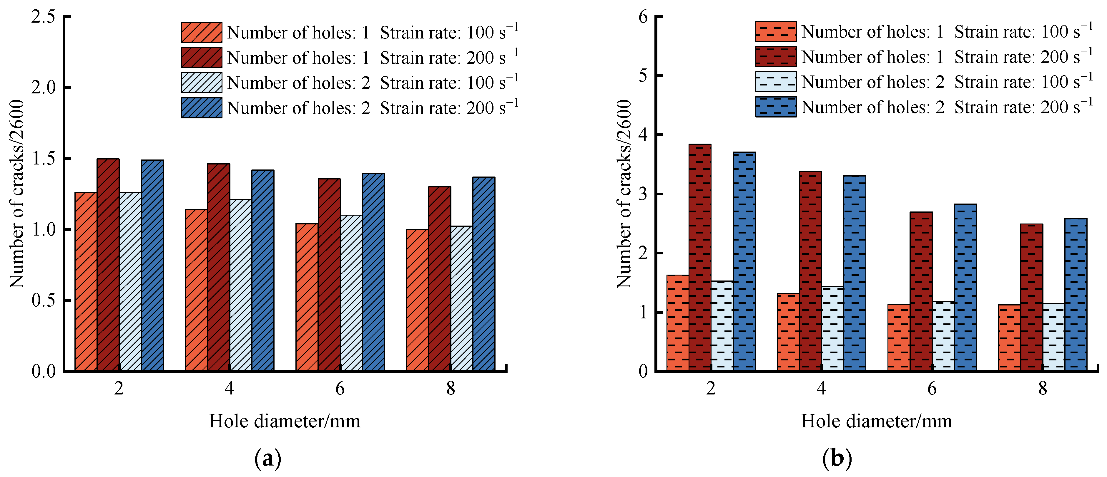
- Under varying strain rate loading conditions, the failure patterns observed in all single-hole specimens were consistent, and double-hole specimens exhibited comparable traits. Analysis of these failure modes through displacement fields revealed that shear cracks were the primary macrocracks, which segmented the specimens into multiple blocks. While initial crack formation in both specimen types began at the specimen ends, crack initiation and propagation in single-hole specimens predominantly occurred around the holes. Conversely, in double-hole specimens, some cracks developed around the rock bridge connecting the two holes.
- The implementation of large-diameter borehole pressure relief measures has been shown to not only enhance the stress distribution surrounding the boreholes but also facilitate the formation of macrocracks by offering displacement space for the movement of end blocks, thereby diminishing the generation of microcracks during the failure process. Furthermore, this study revealed that under high strain rate conditions, the damage at the incident end of the rock specimen was predominantly characterized by shear cracks, which exhibited greater displacement. These insights have the potential to significantly refine borehole pressure relief strategies in deep tunnel applications.
Author Contributions
Funding
Institutional Review Board Statement
Informed Consent Statement
Data Availability Statement
Conflicts of Interest
References
- Farhadian, H. A new empirical chart for rockburst analysis in tunnelling: Tunnel rockburst classification (TRC). Int. J. Min. Sci. Technol. 2021, 31, 603–610. [Google Scholar] [CrossRef]
- Wu, M.; Ye, Y.; Wang, Q.; Hu, N. Development of rockburst research: A comprehensive review. Appl. Sci. 2022, 12, 974. [Google Scholar] [CrossRef]
- Wang, J.; Chen, G.; Xiao, Y.; Li, S. Effect of structural planes on rockburst distribution: Case study of a deep tunnel in Southwest China. Eng. Geol. 2021, 292, 106250. [Google Scholar] [CrossRef]
- Xiao, Y.X.; Feng, X.T.; Li, S.J.; Feng, G.L. Rock mass failure mechanisms during the evolution process of rockbursts in tunnels. Int. J. Rock Mech. Min. Sci. 2016, 83, 174–181. [Google Scholar] [CrossRef]
- Mark, C. Coal bursts in the deep longwall mines of the United States. Int. J. Coal Sci. Technol. 2016, 3, 1–9. [Google Scholar] [CrossRef]
- Wu, J.; Zhang, X.Y.; Yu, L.Y.; Zhang, L.W. Rockburst mechanism of rock mass with structural planes in underground chamber excavation. Eng. Fail. Anal. 2022, 139, 106501. [Google Scholar] [CrossRef]
- Zhou, H.; Meng, F.; Zhang, C.; Hu, D. Analysis of rockburst mechanisms induced by structural planes in deep tunnels. Bull. Eng. Geol. Environ. 2015, 74, 1435–1451. [Google Scholar] [CrossRef]
- Li, D.; Wang, E.; Kong, X.; Ali, M. Mechanical behaviors and acoustic emission fractal characteristics of coal specimens with a pre-existing flaw of various inclinations under uniaxial compression. Int. J. Rock Mech. Min. Sci. 2019, 116, 38–51. [Google Scholar] [CrossRef]
- Zhang, L.M.; Chao, W.W.; Liu, Z.Y.; Cong, Y.; Wang, Z.Q. Crack propagation characteristics during progressive failure of circular tunnels and the early warning thereof based on multi-sensor data fusion. Geomech. Geophys. Geo-Energy Geo-Resour. 2022, 8, 172. [Google Scholar] [CrossRef]
- Cai, W.; Dou, L.; Zhang, M.; Cao, W. A fuzzy comprehensive evaluation methodology for rock burst forecasting using microseismic monitoring. Tunn. Undergr. Space Technol. 2018, 80, 232–245. [Google Scholar] [CrossRef]
- Dexing, L.; Enyuan, W.; Xiangguo, K.; Haishan, J.; Dongming, W.; Muhammad, A. Damage precursor of construction rocks under uniaxial cyclic loading tests analyzed by acoustic emission. Constr. Build. Mater. 2019, 206, 169–178. [Google Scholar] [CrossRef]
- Shi, Y.; Zhang, W.; Wang, Y.H. Seismic elastic RTM with vector-wavefield decomposition. J. Geophys. Eng. 2019, 16, 509–524. [Google Scholar] [CrossRef]
- Gao, F.X.; Wang, Y.H. Radiation pattern analyses for seismic multi-parameter inversion of HTI anisotropic media. J. Geophys. Eng. 2020, 17, 65–75. [Google Scholar] [CrossRef]
- Li, Z.L.; He, X.Q.; Dou, L.M.; Song, D.Z. Investigating the mechanism and prevention of coal mine dynamic disasters by using dynamic cyclic loading tests. Saf. Sci. 2019, 115, 215–228. [Google Scholar] [CrossRef]
- Qiu, L.M.; Liu, Z.T.; Wang, E.Y.; He, X.Q. Early-warning of rock burst in coal mine by low-frequency electromagnetic radiation. Eng. Geol. 2020, 279, 105755. [Google Scholar] [CrossRef]
- Zhu, W.B.; Yu, S.C.; Xu, J.M. Influence of the elastic dilatation of mining-induced unloading rock mass on the development of bed separation. Energies 2018, 11, 785. [Google Scholar] [CrossRef]
- Yang, H.Q.; Zhang, N.; Han, C.L.; Sun, C.L. Stability control of deep coal roadway under the pressure relief effect of adjacent roadway with large deformation: A case study. Sustainability 2021, 13, 4412. [Google Scholar] [CrossRef]
- Fu, Q.; Yang, J.; Wu, X.; Liu, Y.X. Study on the Method of Pressure Relief and Energy Absorption for Protecting Roadway Under Thick and Hard Roof. Rock Mech. Rock Eng. 2023, 56, 7177–7196. [Google Scholar] [CrossRef]
- Wu, W.X.; Gong, F.Q. Dynamic tensile strength weakening effect of pretension stressed red sandstone under impact load. J. Cent. South Univ. 2023, 30, 3349–3360. [Google Scholar] [CrossRef]
- Wu, W.X.; Gong, F.Q.; Jiang, Q. Influence of water on rockburst of surrounding rock in deep circular tunnels under triaxial internal unloading conditions. Tunn. Undergr. Space Technol. 2023, 138, 105165. [Google Scholar] [CrossRef]
- Yang, S.Q.; Chen, M.; Tao, Y. Experimental study on anchorage mechanical behavior and surface cracking characteristics of a non-persistent jointed rock mass. Rock Mech. Rock Eng. 2021, 54, 1193–1221. [Google Scholar] [CrossRef]
- Li, C.C. Principles and methods of rock support for rockburst control. J. Rock Mech. Geotech. Eng. 2021, 13, 46–59. [Google Scholar] [CrossRef]
- Xie, S.R.; Jiang, Z.S.; Chen, D.D.; Wang, E. Failure mechanism of continuous large deformation and a novel pressure relief control technology on the two sides of deep coal roadway. Eng. Fail. Anal. 2023, 144, 106941. [Google Scholar] [CrossRef]
- Liu, S.B.; Liu, H.F.; Li, S.G.; Shuang, H.Q. Experimental study on the effect of unloading rate on the damage of coal with boreholes. Fuel 2024, 357, 129965. [Google Scholar] [CrossRef]
- Xie, S.R.; Jiang, Z.S.; Chen, D.D.; Wang, E. A new pressure relief technology by internal hole-making to protect roadway in two sides of deep coal roadway: A case study. Rock Mech. Rock Eng. 2023, 56, 1537–1561. [Google Scholar] [CrossRef]
- Chen, M.; Zhang, Y.L.; Zang, C.W.; Zhang, G.C. Experimental investigation on pressure relief mechanism of specimens with prefabricated reaming boreholes. Rock Mech. Rock Eng. 2023, 56, 2949–2966. [Google Scholar] [CrossRef]
- Lin, P.; Wong, R.H.; Tang, A. Experimental study of coalescence mechanisms and failure under uniaxial compression of granite containing multiple holes. Int. J. Rock Mech. Min. Sci. 2015, 77, 313–327. [Google Scholar] [CrossRef]
- Li, Y.Y.; Guo, R.W.; Zhang, S.C.; Chen, B. Experimental Study on Pressure Relief Mechanism of Variable-Diameter Borehole and Energy Evolution Characteristics of the Surrounding Rock. Energies 2022, 15, 6596. [Google Scholar] [CrossRef]
- Li, J.; Zhao, J.; Wang, H.C.; Wang, H.C. Fracturing behaviours and AE signatures of anisotropic coal in dynamic Brazilian tests. Eng. Fract. Mech. 2021, 252, 107817. [Google Scholar] [CrossRef]
- Han, Z.Y.; Xie, S.J.; Li, D.Y. Discrete element study on the mechanical behavior of flawed rocks under dynamic compression. Theor. Appl. Fract. Mech. 2022, 121, 103516. [Google Scholar] [CrossRef]
- Zhang, Q.B.; Zhao, J. A review of dynamic experimental techniques and mechanical behaviour of rock materials. Rock Mech. Rock Eng. 2014, 47, 1411–1478. [Google Scholar] [CrossRef]
- Yue, Z.W.; Zhou, J.; Feng, C.; Li, A. Numerical investigation of the effect of holes on dynamic fracturing in multi-flawed granite. Fatigue Fract. Eng. Mater. Struct. 2021, 44, 1883–1896. [Google Scholar] [CrossRef]
- Zou, C.J.; Wong, L.N.Y.; Loo, J.J.; Gan, B.S. Different mechanical and cracking behaviors of single-flawed brittle gypsum specimens under dynamic and quasi-static loadings. Eng. Geol. 2016, 201, 71–84. [Google Scholar] [CrossRef]
- Li, X.B.; Zhou, T.; Li, D.Y. Dynamic strength and fracturing behavior of single-flawed prismatic marble specimens under impact loading with a split-Hopkinson pressure bar. Rock Mech. Rock Eng. 2017, 50, 29–44. [Google Scholar] [CrossRef]
- You, W.; Dai, F.; Liu, Y.; Li, A. Numerical assessment of the rate-dependent cracking behaviours of single-flawed rocks in split Hopkinson pressure bar tests. Eng. Fract. Mech. 2021, 247, 107656. [Google Scholar]
- Li, P.; Cai, M.F.; Gao, Y.B.; Wang, P.T. Dynamic mechanical behavior and cracking mechanism of cross-jointed granite containing a hole. J. Mater. Res. Technol. 2023, 22, 1572–1594. [Google Scholar] [CrossRef]
- Tao, M.; Zhao, H.T.; Momeni, A.; Wang, Y.Q. Fracture failure analysis of elliptical hole bored granodiorite rocks under impact loads. Theor. Appl. Fract. Mech. 2020, 107, 102516. [Google Scholar] [CrossRef]
- Zhao, R.; Tao, M.; Zhao, H.T.; Cao, W.Z. Dynamics fracture characteristics of cylindrically-bored granodiorite rocks under different hole size and initial stress state. Theor. Appl. Fract. Mech. 2020, 109, 102702. [Google Scholar] [CrossRef]
- Zhou, X.; Xie, Y.J.; Long, G.C.; Zeng, X.H. Multi-scale modeling of the concrete SHPB test based on DEM-FDM coupling method. Constr. Build. Mater. 2022, 356, 129157. [Google Scholar] [CrossRef]
- Li, X.B.; Zou, Y.; Zhou, Z.L. Numerical simulation of the rock SHPB test with a special shape striker based on the discrete element method. Rock Mech. Rock Eng. 2014, 47, 1693–1709. [Google Scholar] [CrossRef]
- Pei, P.D.; Dai, F.; Liu, Y.; Wei, M.D. Dynamic tensile behavior of rocks under static pre-tension using the flattened Brazilian disc method. Int. J. Rock Mech. Min. Sci. 2020, 126, 104208. [Google Scholar] [CrossRef]
- Yang, S.Q.; Yin, P.F.; Zhang, Y.C.; Chen, M. Failure behavior and crack evolution mechanism of a non-persistent jointed rock mass containing a circular hole. Int. J. Rock Mech. Min. Sci. 2019, 114, 101–121. [Google Scholar] [CrossRef]
- Qiu, J.D.; Li, D.Y.; Li, X.B. Dynamic failure of a phyllite with a low degree of metamorphism under impact Brazilian test. Int. J. Rock Mech. Min. Sci. 2017, 94, 10–17. [Google Scholar] [CrossRef]
- Li, Y.Z.; Dai, F.; Wei, M.D.; Du, H.B. Numerical investigation on dynamic fracture behavior of cracked rocks under mixed mode I/II loading. Eng. Fract. Mech. 2020, 235, 107176. [Google Scholar] [CrossRef]
- Patel, S.; Martin, C.D. Impact of the initial crack volume on the intact behavior of a bonded particle model. Comput. Geotech. 2020, 127, 103764. [Google Scholar] [CrossRef]
- Huang, Y.H.; Yang, S.Q.; Tian, W.L. Crack coalescence behavior of sandstone specimen containing two pre-existing flaws under different confining pressures. Theor. Appl. Fract. Mech. 2019, 99, 118–130. [Google Scholar] [CrossRef]
- Koyama, T.; Jing, L. Effects of model scale and particle size on micro-mechanical properties and failure processes of rocks—A particle mechanics approach. Eng. Anal. Bound. Elem. 2007, 31, 458–472. [Google Scholar] [CrossRef]
- Manso, J.; Marcelino, J.; Caldeira, L. Effect of the clump size for bonded particle model on the uniaxial and tensile strength ratio of rock. Int. J. Rock Mech. Min. Sci. 2019, 114, 131–140. [Google Scholar] [CrossRef]
- Chen, M.; Zhang, Y.L.; Zhang, G.C.; Zhou, G.L. Discrete element study on mechanical response and pressure relief effect of rock containing variable hole. Theor. Appl. Fract. Mech. 2023, 127, 103976. [Google Scholar] [CrossRef]
- Chen, M.; Yang, S.Q.; Ranjith, P.G.; Zhang, Y.C. Cracking behavior of rock containing non-persistent joints with various joints inclinations. Theor. Appl. Fract. Mech. 2020, 109, 102701. [Google Scholar] [CrossRef]


| Macroscopic Parameter | Specimen | SHPB Bar | |
|---|---|---|---|
| Particle | Radius (mm) | 0.3~0.5 | 0.3~0.9 |
| Density (kg/m3) | 2570 | 7800 | |
| Elastic modulus (GPa) | 8.7 | 210 | |
| Stiffness ratio kn/ks | 2.0 | 2.0 | |
| Friction coefficient | 0.5 | 0.5 | |
| Bond | Effective modulus (GPa) | 8.7 | 210 |
| Stiffness ratio kn/ks | 2.0 | 2.0 | |
| Tensile strength (MPa) | 50 | 1 × 10100 | |
| Shear strength (MPa) | 50 | 1 × 10100 | |
| Experimental Equipment | Drilling Parameters (Diameter/mm) | Strain Rate (s−1) | |
|---|---|---|---|
| Numerical Simulation of SHPB Equipment | Single-Hole | Double-Hole | 60–200 s−1 |
| 2 mm | 2 mm | ||
| 4 mm | 4 mm | ||
| 6 mm | 6 mm | ||
| 8 mm | 8 mm | ||
| Td | Ts | Tp | Tw | |
|---|---|---|---|---|
| (a) |  | |||
| (b) | 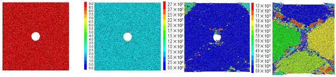 | |||
| (c) |  | |||
| (d) |  | |||
| Td | Ts | Tp | Tw | |
|---|---|---|---|---|
| (a) |  | |||
| (b) | 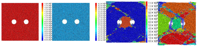 | |||
| (c) | 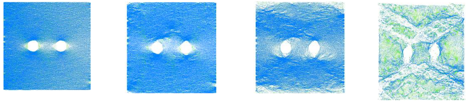 | |||
| (d) |  | |||
| Diameter of Hole | Strain Rate (100 s−1) | Strain Rate (200 s−1) | ||
|---|---|---|---|---|
| Displacement Field | Crack Distribution | Displacement Field | Crack Distribution | |
| 2 mm | 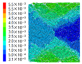 |  |  | 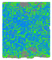 |
| 4 mm | 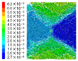 | 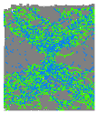 | 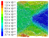 | 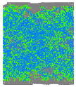 |
| 6 mm | 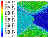 | 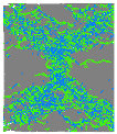 | 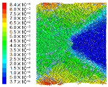 | 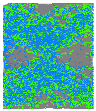 |
| 8 mm | 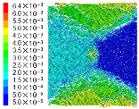 | 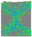 | 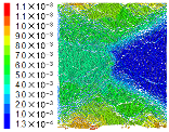 |  |
| Diameter of Hole | Strain Rate (100 s−1) | Strain Rate (200 s−1) | ||
|---|---|---|---|---|
| Displacement Field | Crack Distribution | Displacement Field | Crack Distribution | |
| 2 mm | 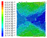 | 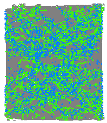 | 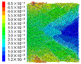 | 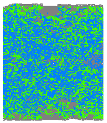 |
| 4 mm | 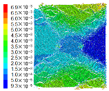 | 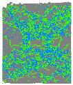 | 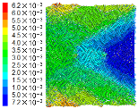 |  |
| 6 mm | 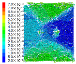 | 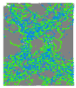 |  | 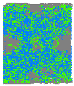 |
| 8 mm | 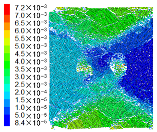 | 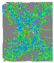 |  |  |
Disclaimer/Publisher’s Note: The statements, opinions and data contained in all publications are solely those of the individual author(s) and contributor(s) and not of MDPI and/or the editor(s). MDPI and/or the editor(s) disclaim responsibility for any injury to people or property resulting from any ideas, methods, instructions or products referred to in the content. |
© 2024 by the authors. Licensee MDPI, Basel, Switzerland. This article is an open access article distributed under the terms and conditions of the Creative Commons Attribution (CC BY) license (https://creativecommons.org/licenses/by/4.0/).
Share and Cite
Zang, C.; Li, Q.; Chen, M.; Wang, X.; Xiao, C.; Tu, H. Study on Dynamic Loading Characteristics of Rock Containing Holes. Appl. Sci. 2024, 14, 3395. https://doi.org/10.3390/app14083395
Zang C, Li Q, Chen M, Wang X, Xiao C, Tu H. Study on Dynamic Loading Characteristics of Rock Containing Holes. Applied Sciences. 2024; 14(8):3395. https://doi.org/10.3390/app14083395
Chicago/Turabian StyleZang, Chuanwei, Qi Li, Miao Chen, Xiaoshan Wang, Can Xiao, and Hongyuan Tu. 2024. "Study on Dynamic Loading Characteristics of Rock Containing Holes" Applied Sciences 14, no. 8: 3395. https://doi.org/10.3390/app14083395
APA StyleZang, C., Li, Q., Chen, M., Wang, X., Xiao, C., & Tu, H. (2024). Study on Dynamic Loading Characteristics of Rock Containing Holes. Applied Sciences, 14(8), 3395. https://doi.org/10.3390/app14083395