Power–Pitch Cascade Control-Based Approach for the Up/Down-Regulated Operation of Large Wind Turbines


Fraunhofer Gesellschaft, e.V., 27572 Bremerhaven, Germany
Appl. Sci. 2024, 14(8), 3396; https://doi.org/10.3390/app14083396
Submission received: 19 March 2024
/
Revised: 9 April 2024
/
Accepted: 16 April 2024
/
Published: 17 April 2024
(This article belongs to the Section Energy Science and Technology)
Abstract
:Modern energy needs require controlled and clean power generation. This demands that the wind turbines be integrated into joint generation groups (wind farms) and the power supply passes be managed by the grid. In this case, the control system of both the wind farm and the individual machines needs the ability to decrease and increase the power output as required. This control system feature is normally implemented by changing control strategies and an associated switching logic. This makes the control system additionally complex and prone to errors. This paper proposes an integrated control configuration for torque and pitch based on a cascade power tracking control (PTC) approach that extends the traditional wind turbine control to enable or disable up/down-regulation. Hence, the resulting control system topology is not complex, and its theoretic dynamic behaviour is known and expected. The new control configuration is studied within a simulation environment with a 20 MW reference machine. The simulation results are very promising from the control performance viewpoint.
1. Introduction
The current interest in integrating wind energy systems into green energy grids has elevated the requirements for the operation of wind turbines. An important aspect of operating a wind turbine inside a power network is that it has to satisfy the same conditions as are normally required for traditional power plants. Since this is not possible, wind turbines are grouped in wind farms, which in turn have to provide the behaviour of a power plant. In other words, wind farms must offer grid services such as, e.g., frequency stabilisation, frequency response, reactive power management, scheduling and dispatching, management of reserves, etc. [1,2]. They are also called ancillary services [3]. Hence, it can be profitable to reduce active power delivery in order to sell reserve power. In addition, there are other reasons to reduce active power generation, such as, for example, when the load dispatching requires only a power fraction of the full power plant capacity, or when the wind turbines have to reduce the rotational speed because of noise generation during the night [4]. On the other hand, sometimes it is very profitable if the power plant is able to deliver a power boot for a short time [5]. In other words, the power plant is required to reduce or increase its power output compared to its nominal value [6].
In the case of wind farms, these features could be achieved by connecting and disconnecting wind turbines from the grid. However, in the case of large three-bladed horizontal-axis wind turbines with variable speed and variable pitch, it is more convenient to reduce or increase the power output of all the machines individually but as a whole according to an individual power profile. Thus, the traditional operation in which a wind turbine should be operated in such a way that it is able to deliver as much power as possible is no longer valid in general, and a new paradigm for wind turbine control is required.
The idea here is to use reference variables provided by the wind farm control for each machine and to configure the local control loops in such a way that the control system works to solve a tracking control problem [7]. Thus, local controllers will be able to follow a power profile, which is precisely the reference variable provided by the wind farm control. If the power profile goes under the power rated value, the operation is called down-regulation [8,9], de-rating [10], or de-loaded operation [11,12]. When the power profile is overrated, the operation can be named up-regulation or up-rating [6]. There are also other reasons for the down-regulation such as, for instance, wake [13] and fatigue reduction [14,15], as well as optimisation of wind farm efficiency [16].
In the traditional concept, wind turbines are operated for power production in two possible operational states. The first one is characterised by wind speeds under the rated value. It is called control in Region II and is mainly implemented by generator torque control. The second one is entered when the wind speed goes over this rated value, i.e., control in Region III. The main control loop is the pitch control, which is used to regulate the rotational speed at its rated value [17]. Since the wind speed is actually a 3D wind field, it is useful to use the effective wind speed to this end. Here, the operating point changes with the wind speed.
In the new concept, the operating point changes with the power profile, and the wind speed acts as a constraint. This change in the control paradigm leads to additional complexity in the control system of the individual wind turbines, where not only the configuration of the control loops but also the control strategies have to be adjusted to accommodate the up/down-regulating control features. In addition, a complicated discrete logic has to be included in order to reconfigure the control system and change strategies.
In the present work, the idea is to design a general control system that can inherently track power references without special changes or reconfigurations. To this end, the classic optimal torque control (OTC) used in Region II is changed to a modified power signal feedback control (PSFC) to make possible the power tracking in the torque control, and the standard collective pitch control (CPC) is complemented in cascade configuration by an external power feedback control loop (PTC). In addition, the controller performance of the PTC is improved by using a nonlinear PI control law instead of the standard one.
The up/down-regulation problem and the corresponding control strategies are presented in Section 2. The new approach is the subject of Section 3. Section 4 is devoted to describe a numerical study based on the simulation of a 20 MW reference wind turbine. Results are shown in Section 5. The conclusions are drawn in Section 6.
2. The Down-Regulation Control Problem
The operation of the large wind turbine can be divided according to the wind speed in several regions, as shown in Figure 1 (see, for instance, [18,19,20,21]). The first region is upper-limited by the cut-in value of the wind speed and characterised by an insufficient wind speed to deliver power. During the operation in the second region, delimited by the cut-in and the rated values, the machine delivers power without reaching its rated values. When the wind speed exceeds the rated value, the wind turbine enters Region III, where the rotational speed is regulated. If the wind speed exceeds the cut-out limit, the machine reaches Region IV, where it is shut down. The transition zones between regions are called Region I½ and Region II½, respectively.
The general control strategies are constant generator speed, constant tip-speed ratio, i.e., tip speed/wind speed, and maximum generator speed. These control strategies are also valid for down-regulation control. The up-regulation problem is practically not treated in the literature, and therefore, it is not presented here.
A down-regulated operation takes place when the machine is forced to operate, delivering less power than it can provide for the current wind speed. The correct operation using a down-regulation control (DRC) strategy presupposes the fulfilment of the following conditions:
- (1)
- If the wind turbine is operated in Region III, the wind speed is always sufficient to carry out the down-regulation, but the up-regulation is limited to the maximum current wind speed;
- (2)
- If the wind turbine is working in Region II, the down-regulation requires that the given power reference Pref is lower than the maximum extractable power Pmax(vw) for the current wind speed vw. Up-regulation is not possible because the wind speed is not enough to scale up the power;
- (3)
- If the power reference Pref is greater than the maximum extractable power Pmax(vw), the down-regulation is not available, but the power output should be as close as the current wind speed makes it possible to the power reference Pref. As in condition 2, up-regulation is also not possible;
- (4)
- The power network is kept as constant and stable as possible. Hence, the power reference for the wind turbine does not change often, and it is provided by the wind farm control through the local supervisory control.
A down-regulation approach can be implemented by adjusting the control strategy of either the torque control loop or the pitch control loop. Down-regulation by using the pitch control reduces the rotational speed first and then keep it constant, which means also a fatigue reduction, but also a lower reaction of the machine. Therefore, it is preferred in general to maintain the rotational speed constant as much as possible and to manipulate the generator torque in order to obtain the desired power output. The advantage of the technique is given by the fact that the control response is faster [9]. However, the rotational speed is normally high, affecting fatigue loads. Another strategy consists in minimising the thrust coefficient Ct. In such case, the power output is reduced in the individual machine while improving the performance of the whole wind farm due to better management of the wake effects [22].
The idea behind the present work is to combine torque and pitch control in order to obtain the advantages of both, by using the power tracking concept in both, including an additional power control loop. Furthermore, the up-regulation characteristic is simply an inherent feature of the power tracking control system used.
3. Description of the New Control Approach
As mentioned in the previous section, the torque and pitch control loops of an individual large wind energy system are consequently modified in order to accommodate power tracking. This will allow up- and down-regulation following an external power reference signal.
3.1. Torque Control Approach
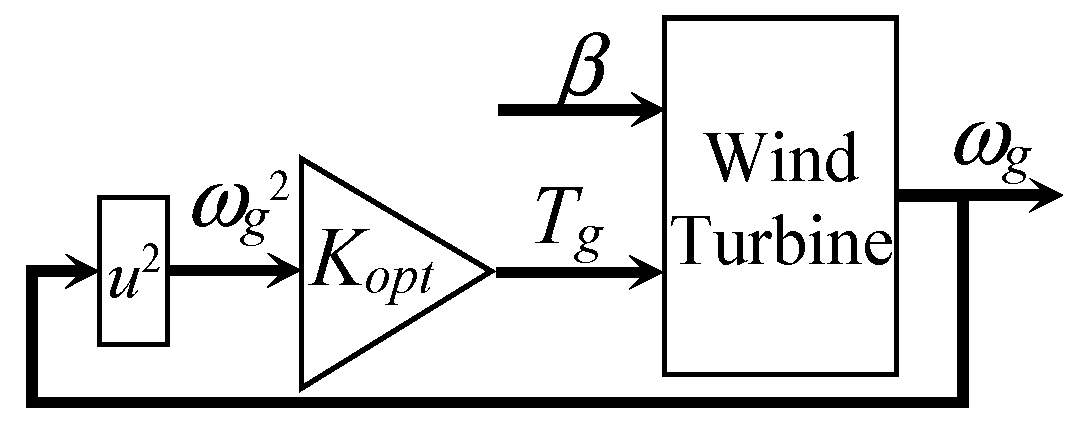
The objective of the classic control approach in Region II is power maximisation, which is normally implemented by using maximum power point tracking (MPPT) algorithms (see, e.g., [23,24]). The most common is the optimal torque control (OTC), whose control law is given by
where Tg is the generator torque, ωg is the generator rotational speed, and Kopt is given by
and parameters η, ρa, R, Cpmax, nx, and λ* are the efficiency, air density, rotor radius, maximum power coefficient, gearbox ratio, and optimal tip-speed ratio, respectively. Variable t symbolises the time. The control scheme is given in Figure 2.
However, the classic OTC approach is not convenient for power control. A more suitable approach for down-regulation control is the torque control with power feedback shown in Figure 3 (see [23]). The lookup table implements the inverse generator characteristic curve.
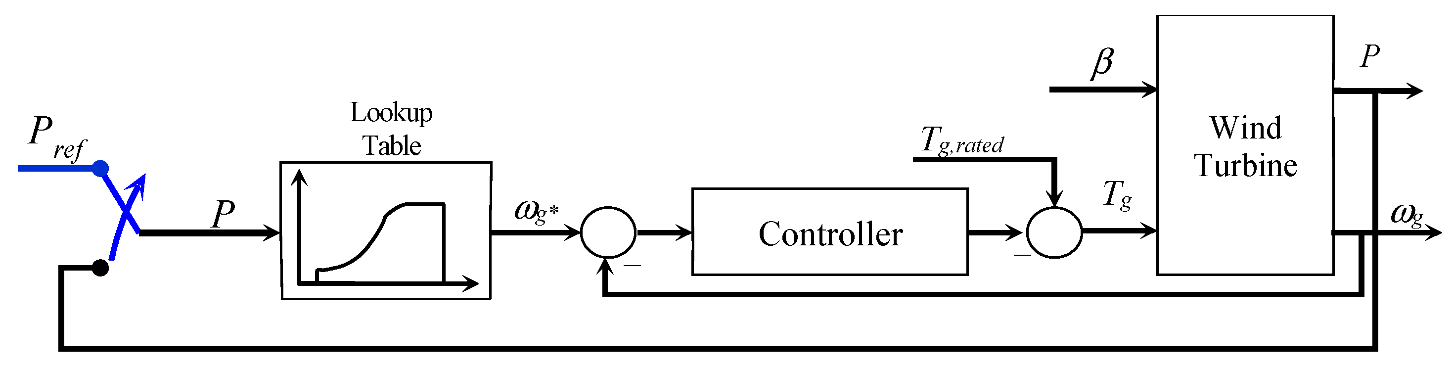
Nevertheless, this control scheme also lacks a reference input and therefore has to be modified in order to overcome the problem. The simplest way is shown in Figure 4. The purpose of the switch is to alternate between the original and new configurations.
The control law is then formulated as
for a PI controller (proportional-integral) with gains Kp and Ki. The function fg−1 represents the inverse generator characteristic function, which is numerically implemented.
3.2. Pitch Control Approach
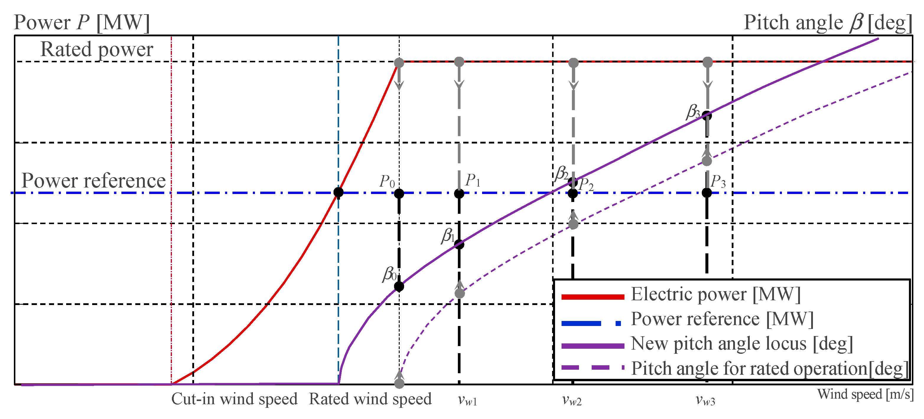
In Region III, the control objective is to keep the power output constant. This is achieved by using a regulator (the collective pitch control, or CPC) that maintains the rotational speed constant for all wind speeds over the rated value. The control variable is the pitch angle, e.g., for a given wind speed vw1, the pitch angle has to be β1 in order to obtain P1, as can be seen in Figure 5. In this case, the power reference is the rated value.
In order to introduce up/down-regulation in wind turbine operation, a power reference is introduced. This causes the locus of pitch angles to move accordingly (see Figure 6). Thus, in order to reach the new power point P1, the pitch angle has to be increased to the new value β1. The idea is illustrated in Figure 6.
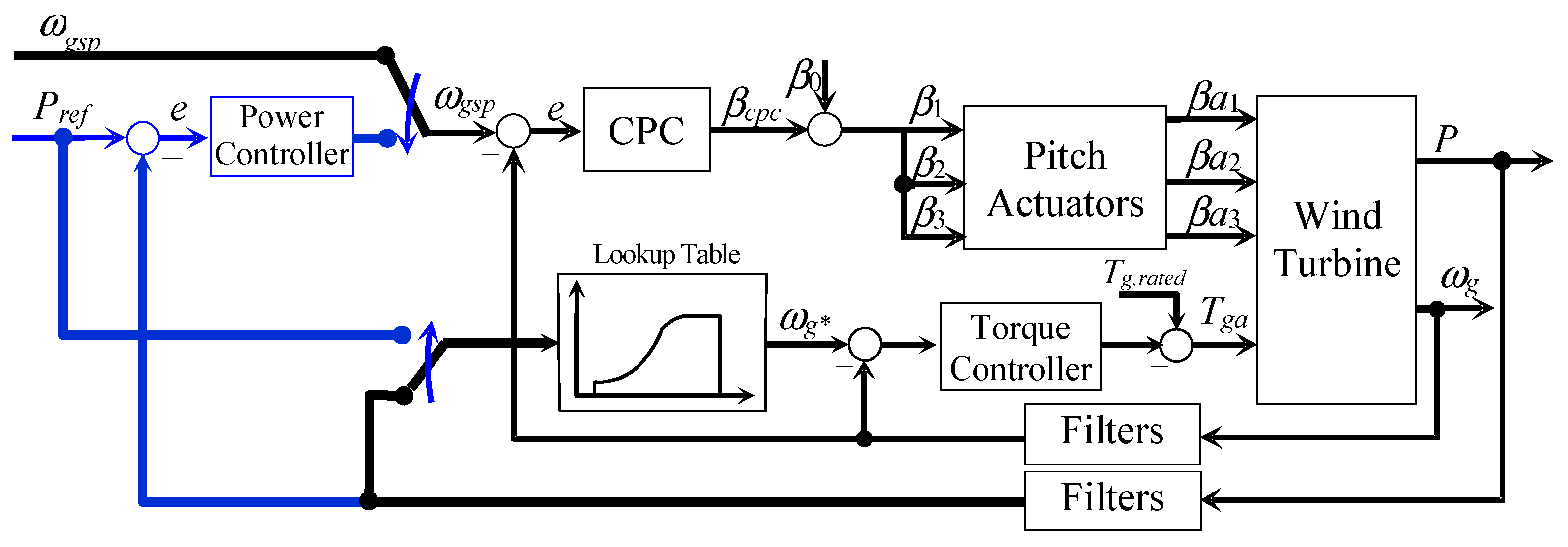
In order to avoid modifications in the topology of the collective pitch control loop, the power tracking control is introduced as an additional control loop in a cascade configuration, as illustrated in Figure 7. A switch is used for a manual change between the classic CPC and the CPC in cascade configuration with a power tracking controller. Lowpass as well as notch filters are included in the feedback way in order to eliminate resonance and vibrating frequencies from the feedback variables, avoiding their amplification in the controllers. The blue lines are used to identify the new control loop.
Following the classic cascade control design [25,26], the inner loop has to be faster but does not need to have much accuracy, so that it can be a simpler controller. The outer loop may be slower but requires a higher level of accuracy, which leads to a more sophisticated controller. Since the intention is not to modify the CPC, which is normally implemented by a PI controller [25,27], a nonlinear PI controller [28,29] is chosen for the outer loop. The nonlinear PI control (NPI) law is given by
where the control error e is (ωgsp − ωg(t)) for the CPC and (Pref − P(t)) for the power tracking control loop. fp and fi are nonlinear functions defined as
Kx1, Kx2, and Kx3 are the controller gains that have to be determined by the designer. The subscript x represents either p or i. Note that by setting Kx2 = 0, the classic PI controller is obtained.
3.3. Combined Torque/Pitch Control Approach
The torque and pitch control loops described in the previous subsections are now combined in Figure 8. By using switches, the topology of the new approach can be reconfigured as a classic one.
3.4. Problem of Power Reference Greater than the Maximum Extractable Power
In normal operating conditions, the case Pref > Pmax(vw) should never take place because it should be filtered first by the supervisor. However, if the scenario materialises despite everything, the low-level controller has to be able to handle it. Therefore, it is analysed here and considered in the implementation.
In the case of Pref > Pmax(vw), the controller tries to reduce the control error, but the power output cannot be increased any more. In such circumstances, a permanent and constant control error appears, which is fed to the controller. Hence, controller output is an unlimited ramp until the integrator saturates. This is similar to the integrator-windup problem, but not because of input saturation but output saturation.
The problem can be solved in two different forms once the condition Pref > Pmax(vw) is detected. The first one consists in resting and switching off the integrator, and the other one consists in setting the maximum extractable power as the new reference, i.e., Pref = Pmax(vw). Both mechanisms are implemented and tested in Section 4.
3.5. Adaptive Control Using a Gain Scheduling Approach
The dynamics of large wind turbines present a nonlinear behaviour. On the other hand, the controllers are linear, and therefore it is expected that the control system performance will deteriorate as the required magnitude of power reduction increases. The same takes place with the CPC. Hence, it is necessary to adapt the controller parameter according to the changes in the operating point. The simplest adaptive control approach is the gain scheduling concept.
In the case of the CPC, it is possible to find analytical equations to recalculate the controller parameters as a function of a scheduling parameter by using a pole placement approach [20]. However, this procedure is not practicable in the case of the power tracking controller because it is internally nested with the CPC, making the derivation very cumbersome. Instead, a numerical procedure will be used here by tabulating the controller gains and activating them according to the power reference value. Between values interpolation is used.
4. Numerical Study
The up/down-regulation control approach has been studied by using a conventional three-bladed, horizontal axis, clockwise, upwind, variable-speed, and variable-pitch reference wind turbine of 20 MW. In addition, a wide wind speed profile and a power profile are used in order to simulate the operation. This reference wind turbine was first proposed in [30] and has been modified and studied for modelling and control in [31].
4.1. Description of the Reference Wind Turbine
The 20 MW wind energy reference converter has first been presented in [30], and it is characterised by a rotor whose diameter is 276 m long. The blades are 135 m long, and the diameter of the hub is 6 m long. The maximum chord of the blade is 10 m, and the tip deflection in the fore-aft direction is 18.1 m. The drive train consists of a low-speed shaft, a high-speed shaft, and a gearbox with a ratio of 1:164. The second order time constant of the rotor is 117.39 s. The generator efficiency is 96.5%, resulting in 20.73 MW of mechanical power for a rated electrical power of 20 MW. The optimal tip-speed ratio is 9.51, which corresponds to a maximum power factor of 0.47268. The rated rotor and generator rotational speeds are 7.16 rpm and 1173.7 rpm, respectively. These values are obtained for a rated wind speed of 10.715 m/s. A scheme of the machine is shown in Figure 9.
4.2. Simulation Setup
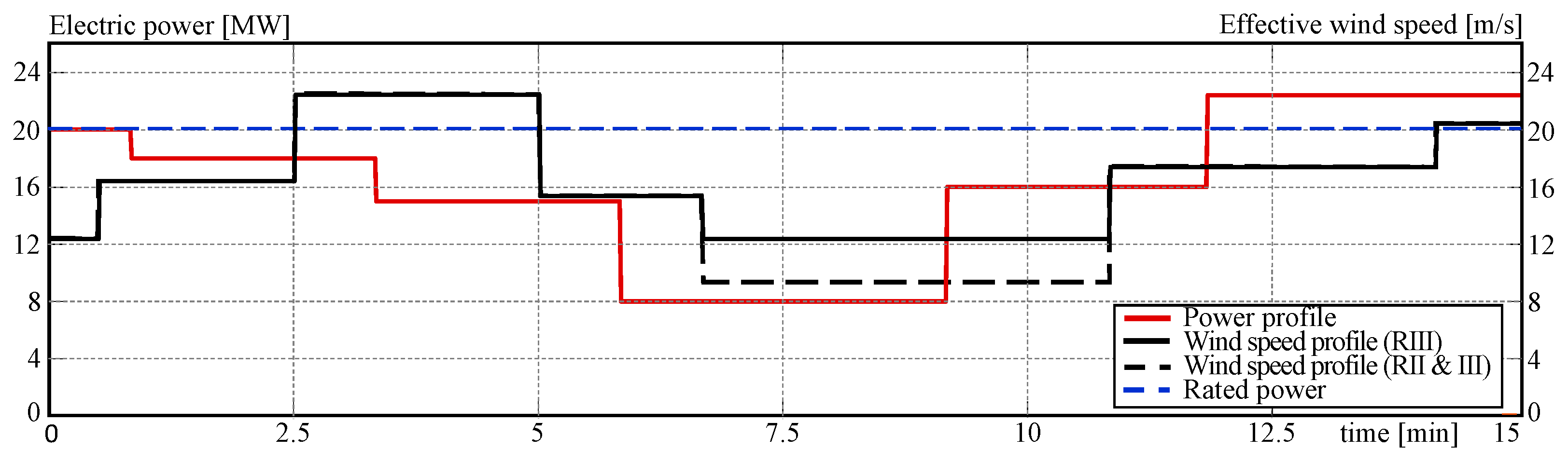
For this study, the wind turbine is operated with a piecewise constant effective wind speed varying between 9.5 and 20.5 m/s. Non-stochastic wind has been chosen in order to clearly appreciate the control behaviour because of changes in the power reference. The first profile is set for Region III and the second profile included Regions II and III. Both profiles are depicted in Figure 10.
In practice, the down-regulated operation is normally limited up to 10% of its rated value, and it takes a long time. Thus, the power profile of Figure 10 is unusual in the application and has been chosen only for the control performance study and demonstration purposes.
The simulation experiments of the reference wind turbine are carried out using OpenFAST v. 3.5.2 (formerly known as FAST) [32], and the control system is implemented in MATLAB® R2021a and Simulink®. The simulation time was set to 900 s (15 min). Several simulation scenarios have been designed in order to evaluate the proposed control system approach. They are summarised in Table 1.
4.3. Controller Design
The complete control system consists of three controllers: a PI controller for the torque control, a second PI controller for the pitch control, and a nonlinear PI controller for the power tracking control. Parameters are obtained by multi-objective optimisation, as used in [33,34]. The obtained parameters are summarised in Table 2.
5. Results and Analysis
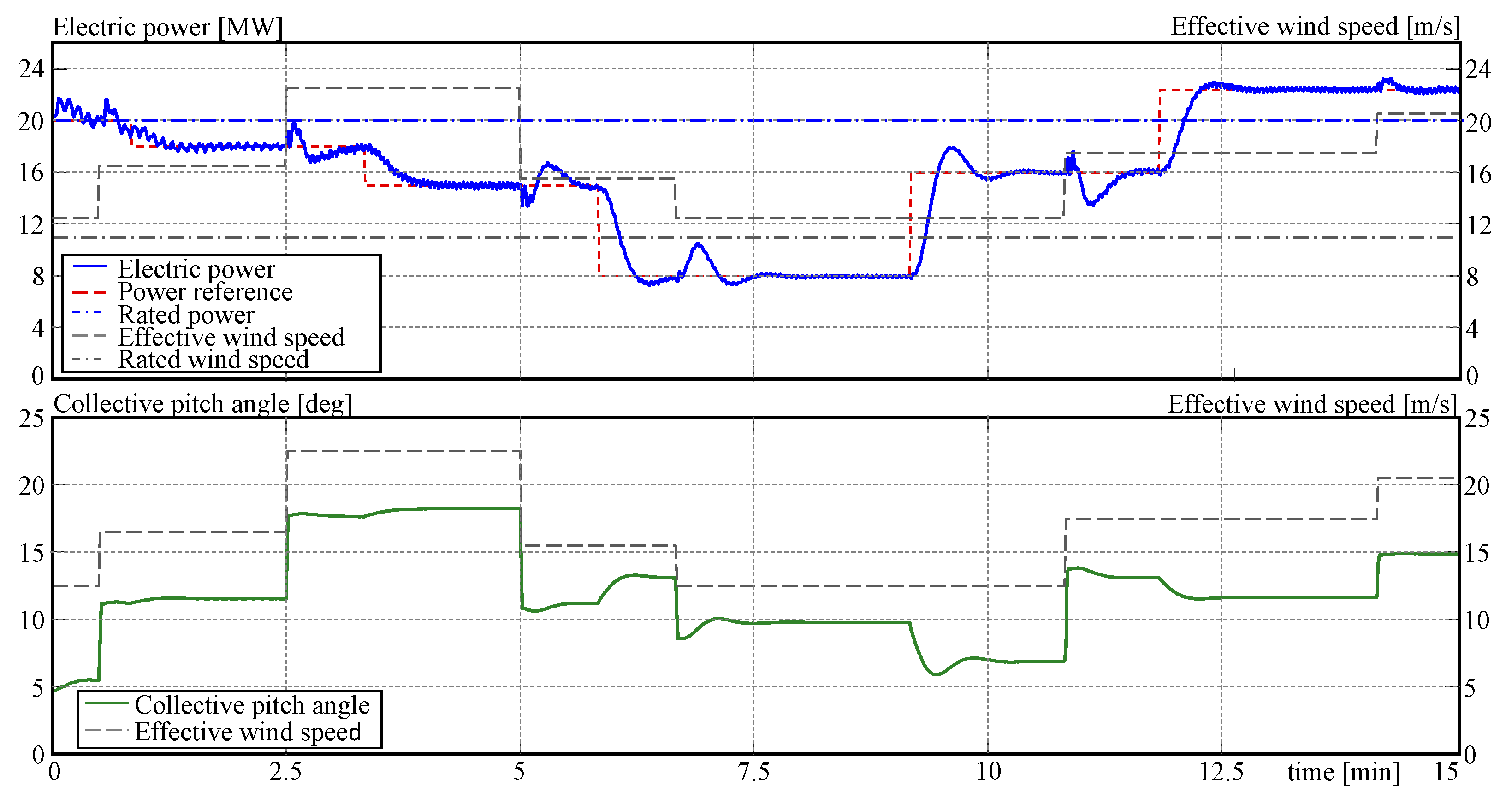
The first experiment consists of tracking the power reference for a stepwise changing effective wind speed over 12 m/s, i.e., in Region III. Both the output power and pitch angle satisfy the operating conditions, as shown in Figure 11.
As satisfied operational conditions, it is meant here that the power output follows the reference signal despite changes in wind speed, disturbances are compensated, and the output of the pitch controller never saturates.
The settling time for a tolerance band of 5% is normally calculated as three times the second order time constant Ts (see, e.g., [35,36]). Since Ts = 117.39 s for the rotor, the open-loop settling time is about 352.18 s. According to the simulation results, the settling time varies from 45 to 65 s, depending on the operating time, which corresponds to a reduction of about five times regarding the open-loop value. Thus, they can be considered good numbers for a machine with a very high inertia. The abrupt changes in wind speed are constant disturbances to the control system, which eliminates them in a short time of about 27 s. It should be mentioned that such abrupt changes are not realistic, and they are used to test the behaviour of the control system in the worst conditions. The gain scheduling adaption as well as the correction for Pref > Pmax are not necessary in this case.
It is important to note that the power reference after 9.2 min is over the rated value, i.e., under up-regulation conditions. Thus, the control system responds correctly to both down-regulated and up-regulated operations.
In the second experiment, the wind profile is changed such that between 6.7 and 10.85 min, the operation takes place in Region II. Moreover, between 9.15 and 10.85 min, Pref > Pmax. The corresponding curves can be observed in Figure 12.
It is possible to observe that the control performance deteriorates notoriously when the wind speed falls below 10 m/s. This is because the operating point is far away from the rated value, and the controller with fixed parameters is no longer optimal. In addition, the integrator of the PI controller integrates a constant control error, and the consequence becomes evident at the end of time 10.85 when the controller loses its tracking property and the power output becomes unacceptable.
This situation should be prevented by the supervisor, but if that is not the case, the local controller has to be able to manage the situation to avoid the tracking operation or, sometimes, the system stability. Thus, the third experiment consists of testing mechanisms to avoid output saturation affecting the tracking control system.
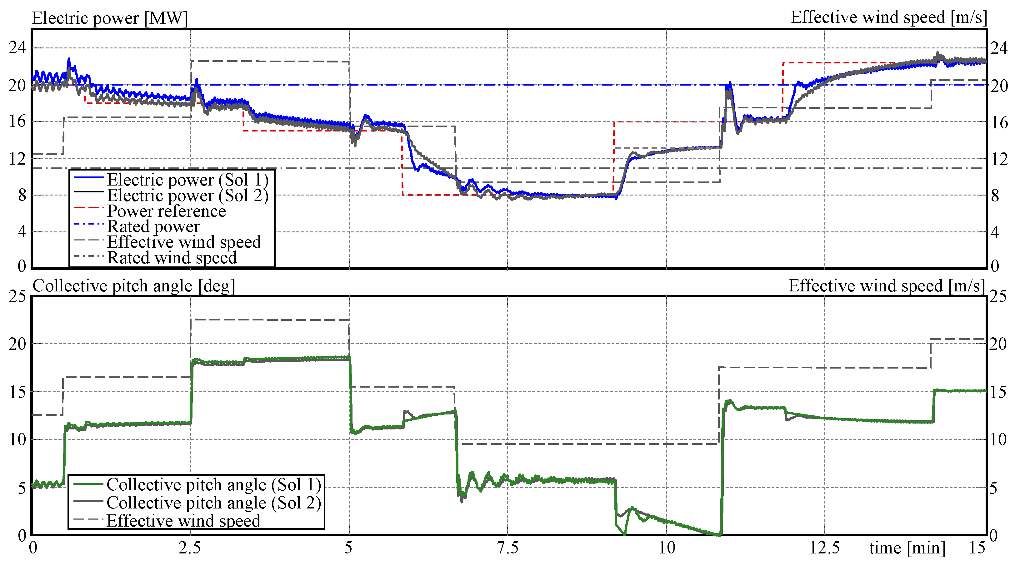
To this end, two mechanisms have been implemented and evaluated. The first one consists of switching off the integrator and resetting its internal states. The procedure can be formulated by
where xi is the internal state of the integrator. The second mechanism is to switch the reference signal to the maximum available power, i.e.,
All simulation conditions are the same as for the previous experiment. Both mechanisms lead to different dynamic behaviours. Therefore, controller parameters needed to be tuned separately for each case. This is the reason why the simulation curves are similar but not identical. Results are presented in Figure 13, where it is observed that both mechanisms fulfil the mission correctly with a similar performance. Finally, power reference switching will be used in the future because its implementation is simpler.
The last experiment maintains all conditions as before but includes the gain scheduling adaption. However, the interdependence between the CPC and PTC parameters is strong in a nonlinear relationship. Moreover, the parameters of the CPC are also gain-scheduled. For this reason, it is difficult to establish for each gain of the PTC a clear functional dependence between power reference values. Therefore, the present solution is a lookup table implementation.
To this end, ten values of the power reference are selected in 2.5 MW steps, and the controller parameters are obtained for each one. The gains are organised in a lookup table whose input is the power reference, and the transitions are smoothed by linear interpolation. The values are given in Table 3.
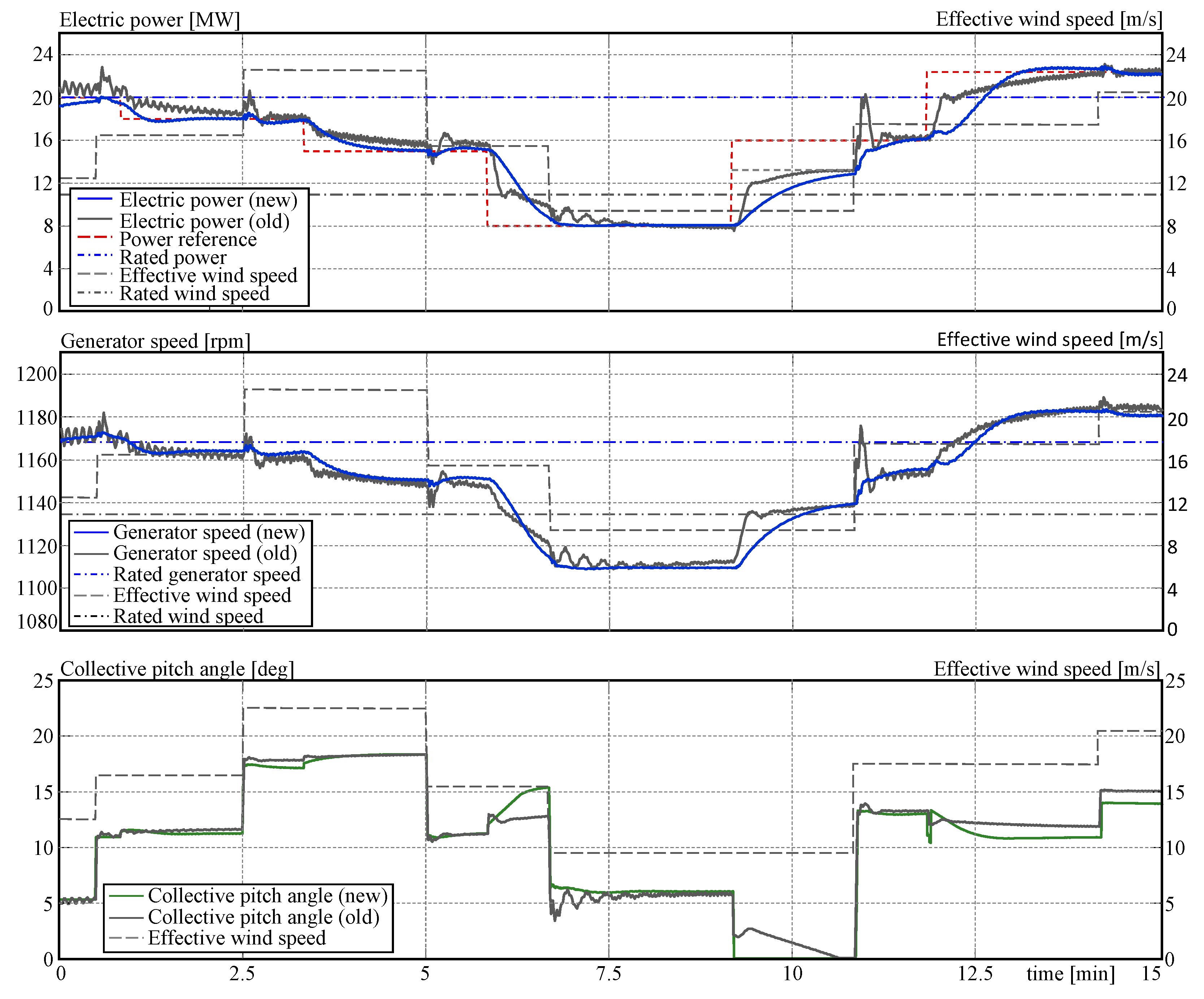
The large values in Table 3 might be striking. This is due to the fact that the simulation programme is designed in the MKS system, i.e., the power is given internally in watts. Since the reference is expressed in megawatts, the variables are multiplied by 106. This last simulation experiment considers together all characteristics of the new approach. Therefore, not only the power but also the generator speed are included in the analysis. The results are shown in Figure 14, where one observes that the parameter adaption improves the controller performance at every value of the power reference as well as the generator speed. The generator speed is correctly adjusted following the reference provided by the power controller. The results of the previous experiment (solid grey lines) are also included here for comparison purposes.
It is important to mention that it seems that the pitch angle suffers unrealistic step jumps. However, this is an incorrect appreciation. The pitch actuators have a maximum speed of ±8 deg/s. Hence, a maximum step of 11 degrees is covered in 1.4 s, an amount that cannot be observed on the minute-scaled axis.
6. Conclusions
In the present contribution, an integral control concept that can be used as standard control as well as for the up- and down-regulation problem is presented. This approach changes the classic OTC with a modified PSFC for the torque control loop and complements the CPC with a power tracking control, which is connected in a cascade configuration. By using a switching variable, the standard and the new control configurations can be interchanged.
The control system works correctly in Regions II and III. In the case that the power reference exceeds the maximum extractable power in Region II, an additional mechanism intervenes in order to prevent performance depreciation and loss of stability due to the unlimited controller integration produced by the output saturation. Moreover, the need for a gain scheduling adaption becomes apparent when the power reference changes strongly regarding its rated value. The implemented gain scheduling approach is simple and sufficient to maintain control performance.
An important aim of this work is the proof of concept, which has been successfully verified. However, some aspects can be improved, and others need to be studied in a second phase. For instance, there is some margin to improve the performance through parameter tuning. The settling time as well as the overshoots can be reduced by adding the corresponding objective functions in the multi-objective optimisation. The gain scheduling mechanism should be deeply studied in order to find an analytical relationship depending on a scheduling parameter. This can improve control performance by more accuracy and smoother changes in the controller parameters.
Load behaviour and fatigue are also topics to be studied, and the implementation and testing in the hardware-in-the-loop real-time environment are future steps as well. Moreover, all the studies mentioned before are concerning single turbines, but after finishing all of them, the joint dynamic behaviour of groups of wind turbines should be undertaken with the objective of predicting the response of wind farms.
Funding
This work has been financed by the Federal Ministry of Economic Affairs and Climate Action (BMWK).
Data Availability Statement
The data presented in this study are available on request from the corresponding author. The data are not publicly available due to institution regulations.
Acknowledgments
The author would like to thank Mabel Kociuba for the invaluable support provided during the manuscript preparation.
Conflicts of Interest
The author declares no conflict of interest. The funders had no role in the design of the study, in the collection, analyses, or interpretation of data, in the writing of the manuscript, or in the decision to publish the results.
Abbreviations
| BMWK | Federal Ministry of Economic Affairs and Climate Action (in German) |
| CPC | Collective Pitch Control |
| DRC | Down-Regulation Control |
| MKS | Meter Kilogram Second |
| MPPT | Maximum Power Point Tracking |
| NPI | Nonlinear Proportional Integral |
| OTC | Optimal Torque Control |
| PI | Proportional Integral |
| PSFC | Power Signal Feedback Control |
| Nomenclature | |
| Parameters | |
| β0 | Pitch angle at the operating point, rad |
| Cp | Power coefficient, — |
| Cp,max | Maximum value of the power coefficient, — |
| Kp, Ki | Gains of PI controller |
| Kp1, Kp2, Kp3, Ki1, Ki2, Ki3 | Gains of NPI controller |
| nx | Gearbox ratio, — |
| Prated | Rated power, MW |
| R | Rotor radius, m |
| Tg,rated | Rated generator torque, kg m2 |
| vci | Cut-in value for the wind speed, m/s |
| vco | Cut-out value for the wind speed, m/s |
| vv,rated | Rated value for the wind speed, m/s |
| λ | Tip-speed ratio |
| λ* | Optimal tip-speed ratio |
| η | Efficiency |
| ρa | Density of air, kg/m3 |
| ωg,rated | Rated value of the generator speed, rad/s |
| ωgsp | Set point for the generator speed, rad/s |
| Variables | |
| β | Pitch angle, rad |
| βa | Output of pitch actuators, rad |
| e | Control error |
| λ | Tip-speed ratio, — |
| P | Power, MW |
| Pref | Power reference, MW |
| t | Time |
| Tga | Output of the torque controller, kg m2 |
| Tg | Generator torque (on the low-speed shaft), kg m2 |
| vv | Wind speed, m/s |
| ωg | Generator speed, rad/s |
| ωg* | Set point for the torque controller, rad/s |
| xi | State variable of integrator |
References
- Mirzaei, M.; Soltani, M.; Poulsen, N.K.; Niemann, H.H. Model based active power control of a wind turbine. In Proceedings of the 2014 American Control Conference, Portland, OR, USA, 4–6 July 2014; pp. 5037–5042. [Google Scholar] [CrossRef]
- Aho, J.; Buckspan, A.; Laks, J.; Dunne, F.; Pao, L.; Fleming, P.; Churchfield, M.; Jeong, Y.; Johnson, K. A tutorial of wind turbine control for supporting grid frequency through active power control. In Proceedings of the 2012 American Control Conference (ACC), Montreal, QC, Canada, 27–29 June 2012; pp. 3120–3131. [Google Scholar] [CrossRef]
- Miller, N.W.; Clark, K. Advanced controls enable wind plants to provide ancillary services. In Proceedings of the IEEE PES General Meeting, Minneapolis, MN, USA, 25–29 July 2010; pp. 1–6. [Google Scholar] [CrossRef]
- Rivarola, A.; Gambier, A. Control of large wind energy systems for acoustic noise reduction by using multi-objective optimal control. IFAC-Pap. 2023, 56, 11255–11260. [Google Scholar] [CrossRef]
- Soini, V. Wind power intermittency and the balancing power market: Evidence from Denmark. Energy Econ. 2021, 100, 105381. [Google Scholar] [CrossRef]
- Rebello, E.; Watson, D.; Rodgers, M. Developing, implementing and testing up and down regulation to provide AGC from a 10 MW wind farm during varying wind conditions. IOP J. Phys. Conf. Ser. 2018, 1102, 012032. [Google Scholar] [CrossRef]
- Zalkind, D.S.; Nicotra, M.M.; Pao, L.Y. Constrained power reference control for wind turbines. Wind Energy 2022, 25, 914–934. [Google Scholar] [CrossRef]
- Zhu, J.; Ma, K.; Soltani, M.; Hajizadeh, A.; Chen, Z. Comparison of loads for wind turbine down-regulation strategies. In Proceedings of the 11th Asian Control Conference (ASCC), Gold Coast, QLD, Australia, 17–20 December 2017; pp. 2784–2789. [Google Scholar] [CrossRef]
- van der Hoek, D.; Kanev, S.; Engels, W. Comparison of down-regulation strategies for wind farm control and their effects on fatigue loads. In Proceedings of the 2018 Annual American Control Conference (ACC), Milwaukee, WI, USA, 27–29 June 2018; pp. 3116–3121. [Google Scholar] [CrossRef]
- Aho, J.; Pao, L.; Fleming, P. An active power control system for wind turbines capable of primary and secondary frequency control for supporting grid reliability. In Proceedings of the 51st AIAA Aerospace Sciences Meeting including the New Horizons Forum and Aerospace Exposition 2013, Grapevine, TX, USA, 7–10 January 2013; pp. 1–13. [Google Scholar] [CrossRef]
- Ma, H.; Chowdhury, B. Working towards frequency regulation with wind plants: Combined control approaches. IET Renew. Power Gener. 2010, 4, 308–316. [Google Scholar] [CrossRef]
- Elorza, I.; Calleja, C.; Pujana-Arrese, A. On wind turbine power delta control. Energies 2019, 12, 2344. [Google Scholar] [CrossRef]
- Ma, K.; Zhu, J.; Soltani, M.; Hajizadeh, A.; Chen, Z. Wind turbine down-regulation strategy for minimum wake deficit. In Proceedings of the 11th Asian Control Conference, Gold Coast, QLD, Australia, 17–20 December 2017; pp. 2652–2656. [Google Scholar] [CrossRef]
- Juankorena, X.; Esandi, I.; Lopez, J.; Marroyo, L. Method to enable variable speed wind turbine primary regulation. In Proceedings of the International Conference on Power Engineering, Energy and Electrical Drives, Lisbon, Portugal, 18–20 March 2009; pp. 495–500. [Google Scholar]
- Antrain Juangarcia, D.; Eguinoa, I.; Knudsen, T. Derating a single wind farm turbine for reducing its wake and fatigue. J. Phys. Conf. Ser. 2018, 1037, 032039. [Google Scholar] [CrossRef]
- Lio, W.H.; Mirzaei, M.; Larsen, G.C. On wind turbine down-regulation control strategies and rotor speed set-point. J. Phys. Conf. Ser. 2018, 1037, 032040. [Google Scholar] [CrossRef]
- Gambier, A. Pitch control of three bladed large wind energy converters—A Review. Energies 2021, 14, 8083. [Google Scholar] [CrossRef]
- Bianchi, F.D.; de Battista, H.; Mantz, R.J. Wind Turbine Control Systems; Springer Nature: London, UK, 2007. [Google Scholar]
- Burton, T.; Jenkins, N.; Sharpe, D.; Bossanyi, E. Wind Energy Handbook, 2nd ed.; John Wiley & Sons: Chichester, UK, 2011. [Google Scholar]
- Gambier, A. Control of Large Wind Energy Systems; Springer Nature: Basel, Switzerland, 2022. [Google Scholar]
- Manwell, J.F.; McGowan, J.G.; Rogers, A.L. Wind Energy Explained. Theory, Design and Applications; John Wiley & Sons Ltd.: Chichester, UK, 2009. [Google Scholar]
- Meng, F.; Wai, A.; Lio, H.; Liew, J. The effect of minimum thrust coefficient control strategy on power output and loads of a wind farm. J. Phys. Conf. Ser. 2020, 1452, 012009. [Google Scholar] [CrossRef]
- Abdullah, M.A.; Yatim, A.H.M.; Tan, C.W.; Saidur, R. A review of maximum power point tracking algorithms for wind energy systems. Renew. Sustain. Energy Rev. 2012, 16, 3220–3227. [Google Scholar] [CrossRef]
- Kumar, D.; Chatterjee, K. A review of conventional and advanced MPPT algorithms for wind energy systems. Renew. Sustain. Energy Rev. 2016, 55, 957–970. [Google Scholar] [CrossRef]
- Visioli, A. Practical PID Control; Springer: London, UK, 2006. [Google Scholar]
- Wang, L. PID Control System Design and Automatic Tuning Using MATLAB/Simulink; JohnWiley & Sons Ltd.: Chichester, UK, 2020. [Google Scholar]
- Åström, K.J.; Hagglund, T. Advanced PID Control; ISA—The Instrumentation, Systems, and Automation Society: Research Triangle Park, NC, USA, 2005. [Google Scholar]
- Gambier, A.; Nazaruddin, Y. Nonlinear PID control for pitch systems of large wind energy converters. In Proceedings of the 2018 IEEE Conference on Control Technology and Applications, Copenhagen, Denmark, 21–24 August 2018; pp. 996–1001. [Google Scholar]
- Isayed, B.M.; Hawwa, M.A. A nonlinear PID control scheme for hard disk drive servosystems. In Proceedings of the 15th Mediterranean Conference on Control and Automation, Athens, Greece, 27–29 June 2007; pp. 1–6. [Google Scholar]
- Ashuri, T.; Martins JRR, A.; Zaaijer, M.B.; van Kuik, G.A.M.; van Bussel, G.J.W. Aeroservoelastic design definition of a 20 MW common research wind turbine model. Wind Energy 2016, 19, 2071–2087. [Google Scholar] [CrossRef]
- Chamoli, S.; Gambier, A. Modelling, parametrization and observer design of a 20 MW reference wind turbine for control purposes. J. Phys. Conf. Ser. 2020, 1618, 022031. [Google Scholar] [CrossRef]
- Jonkman, J.; Jonkman, B. FAST modularization framework for wind turbine simulation: Full-system linearization. J. Phys. Conf. Ser. 2016, 753, 082010. [Google Scholar] [CrossRef]
- Gambier, A. Multiobjective optimal control of wind turbines: A survey on methods and recommendations for the implementation. Energies 2022, 15, 567. [Google Scholar] [CrossRef]
- Gambier, A.; Jipp, M. Multi-objective optimal control: An introduction. In Proceedings of the Asian Control Conference, Kaohsiung, Taiwan, 15–18 May 2011; pp. 1084–1089. [Google Scholar]
- Ogata, K. Modern Control Engineering, 5th ed.; Prentice Hall: Boston, MA, USA, 2009. [Google Scholar]
- Golnaraghi, F.; Kuo, B. Automatic Control Systems; McGraw-Hill Education: New York, NY, USA, 2017. [Google Scholar]
Figure 1.
Operation regions of a modern wind energy converter.
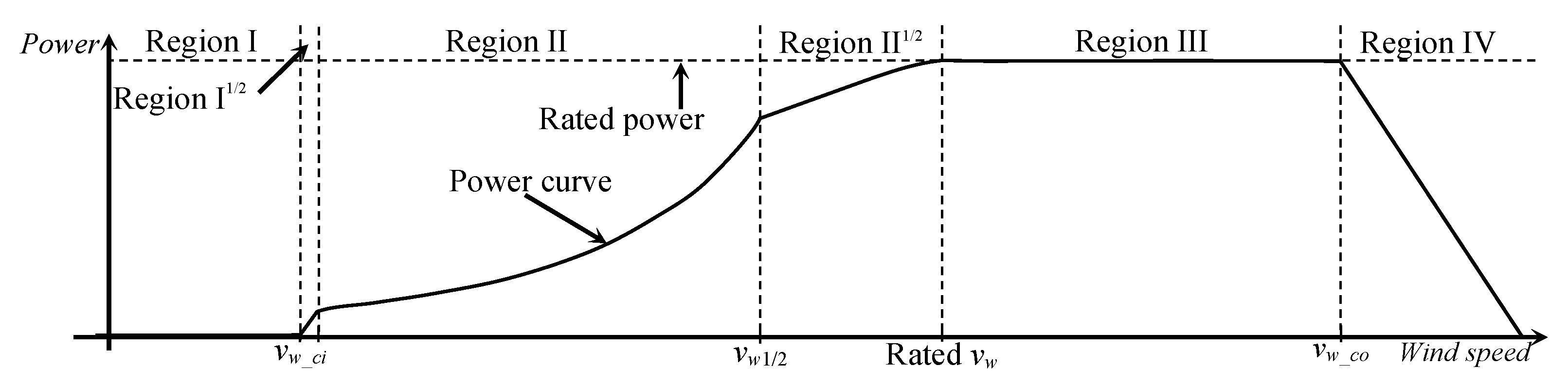
Figure 2.
Torque control system configuration for optimal torque control (OTC).

Figure 3.
Torque control system configuration with power feedback.
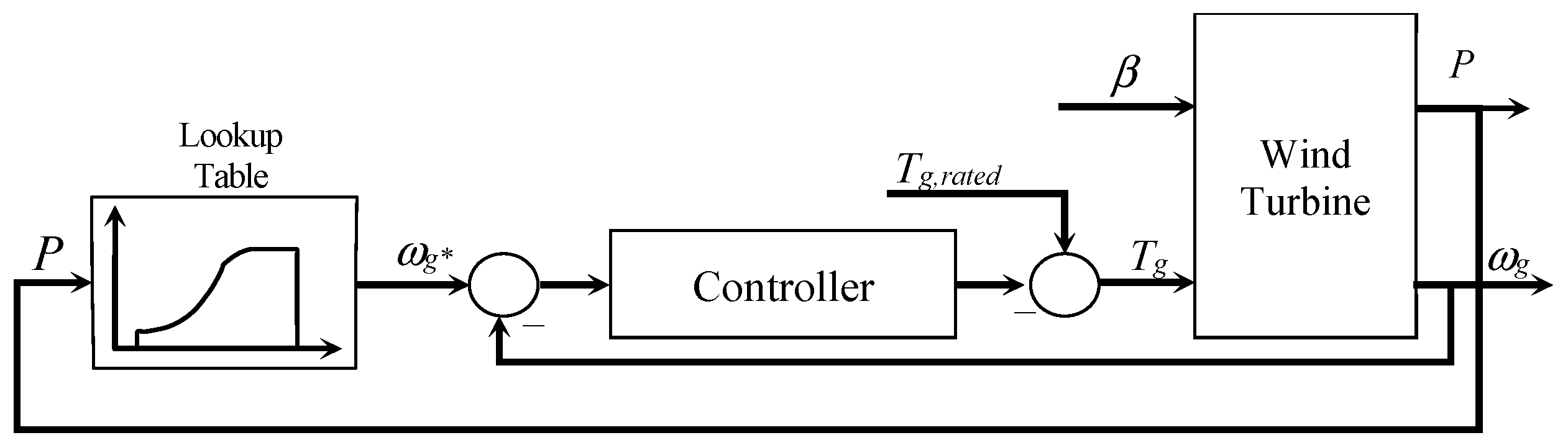
Figure 4.
Torque control system configuration with power reference.

Figure 5.
Typical power curve of a wind turbine and locus of pitch angles.
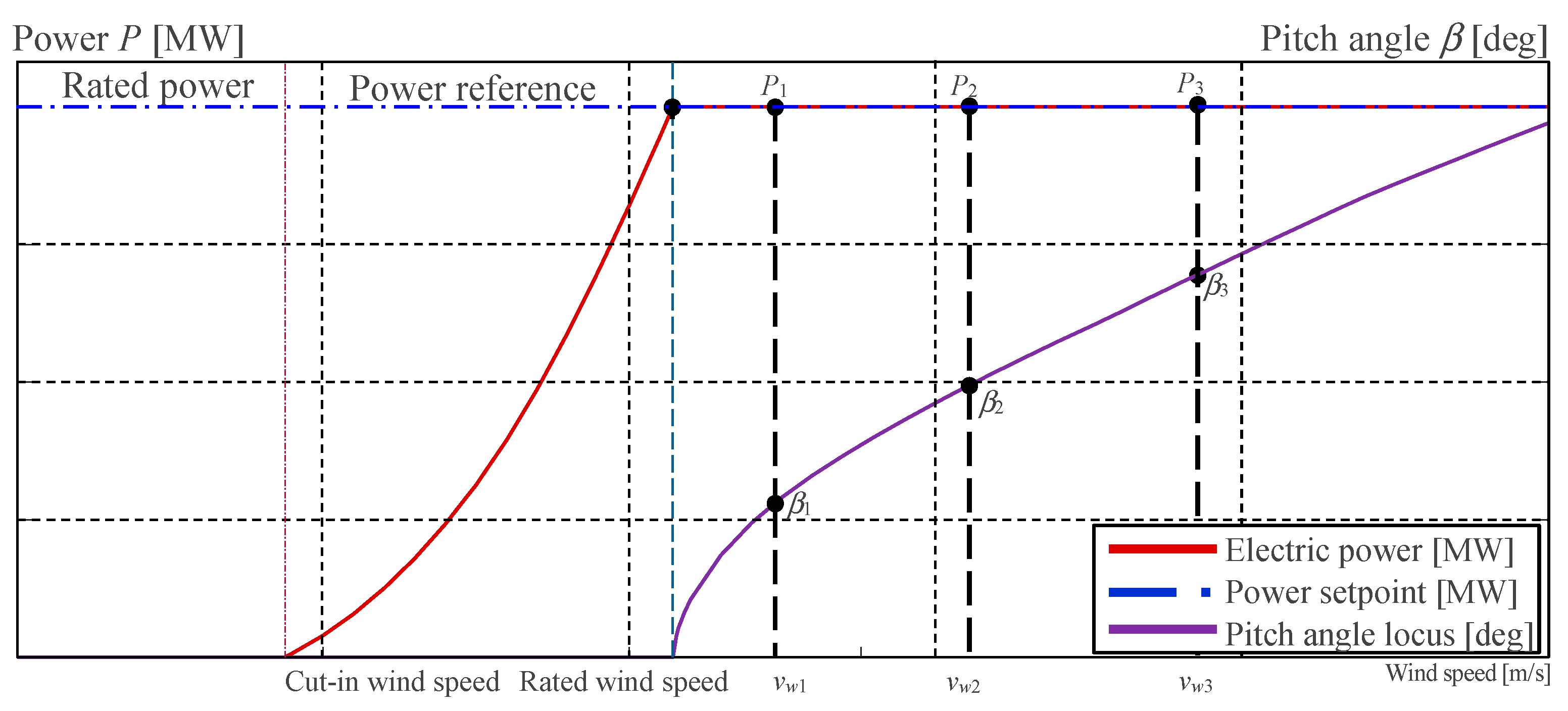
Figure 6.
Power curve of a wind turbine and locus of pitch angles for a given power reference.

Figure 7.
Power tracking control (PTC) and collective pitch control in cascade configuration.
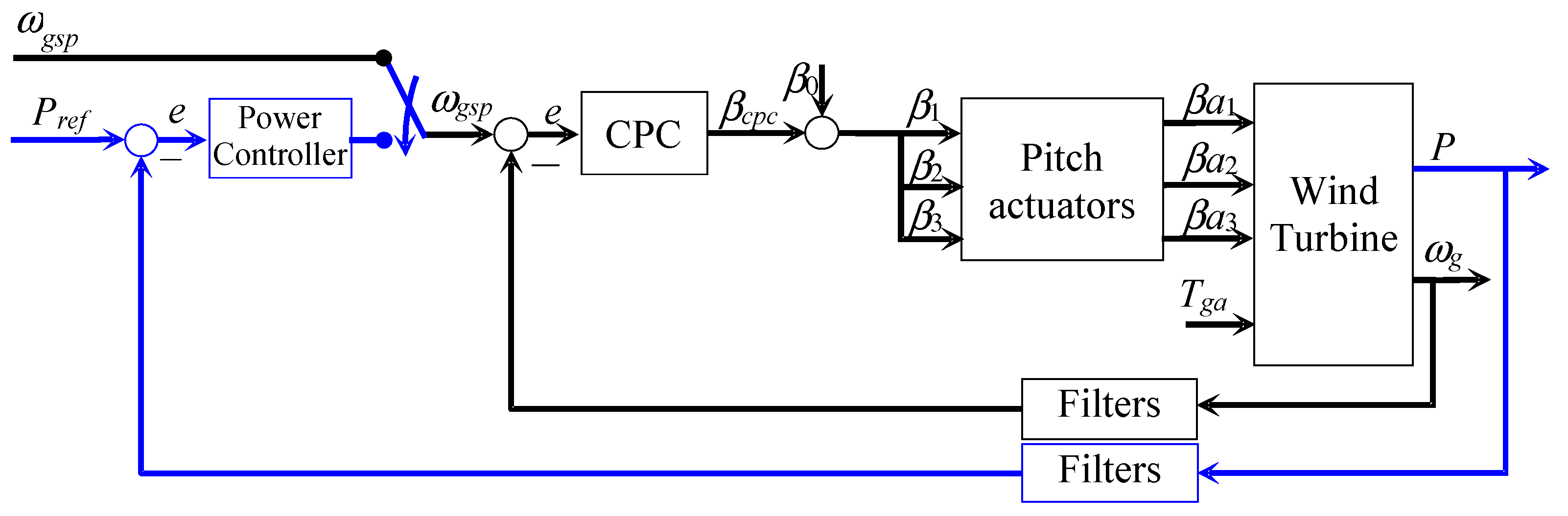
Figure 8.
Power tracking control for torque and pitch control in cascade configuration.

Figure 9.
Descriptive scheme of the 20 MW wind turbine.
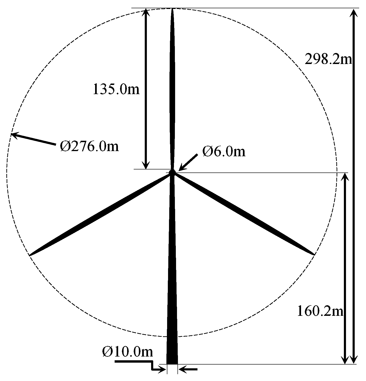
Figure 10.
Power and wind speed profiles for simulation purposes.

Figure 11.
Power tracking control in Region III.

Figure 12.
Power tracking control in Region III for Pref > Pmax without gain scheduling.
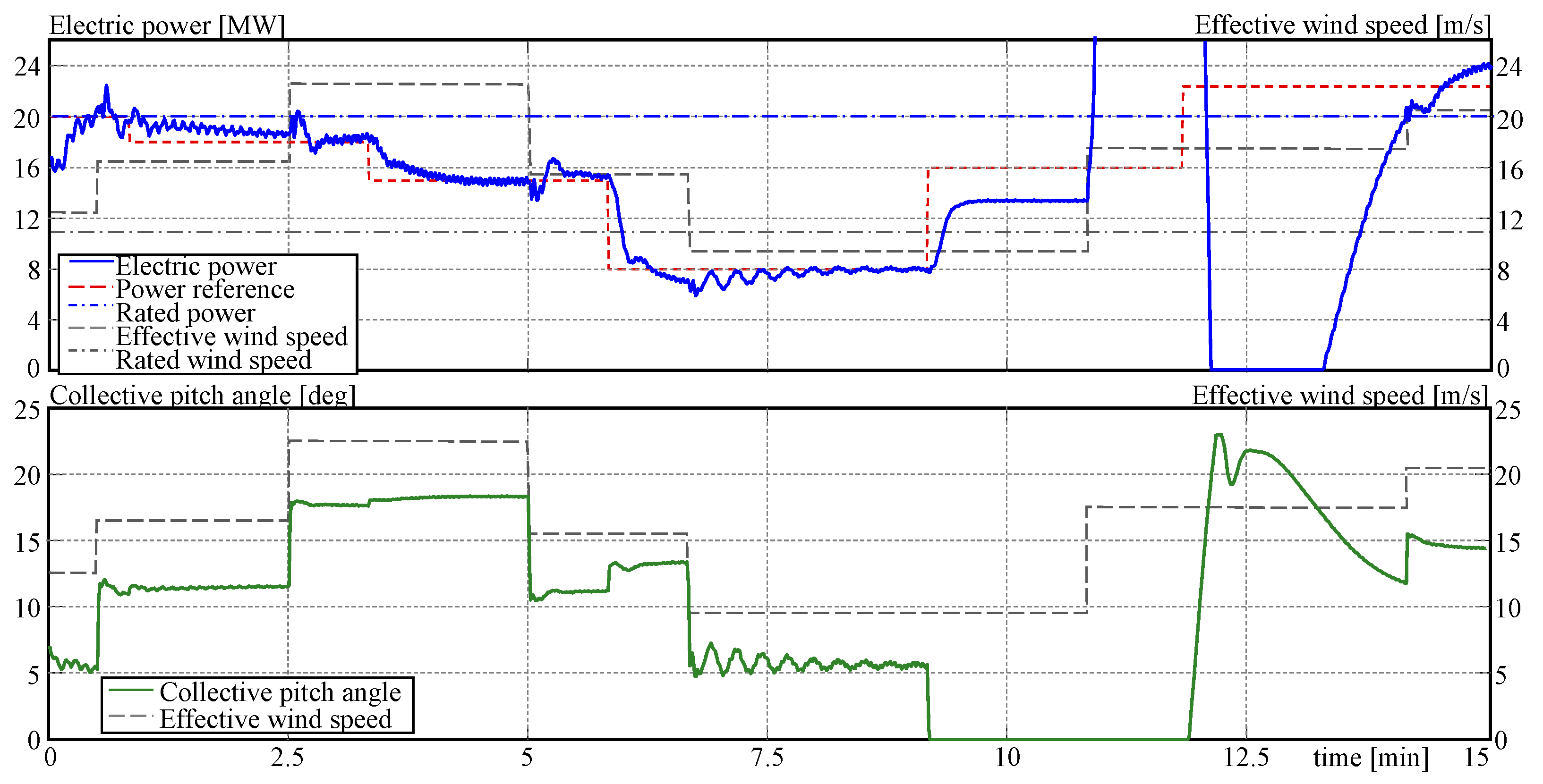
Figure 13.
Power tracking control with compensation for power output saturation.

Figure 14.
Power tracking control system with gain scheduling. Power and generator speed.

Table 1.
Simulation scenarios for up/down-regulation control.
| Scenario | Wind Profile | Description |
|---|---|---|
| Scenario 1 | Region III | Tracking power control on Region III. |
| Scenario 2 | Region II & III | Tracking power control with Pref < Pmax. No gain scheduling. |
| Scenario 3 | Region II & III | Tracking power control with Pref > Pmax and integrator reset. No gain scheduling. |
| Scenario 4 | Region II & III | Tracking power control with Pref > Pmax and power reference change. No gain scheduling. |
| Scenario 5 | Region II & III | Tracking power control with Pref > Pmax, power reference change, and gain scheduling. |
Table 2.
Controller parameter for all controllers.
| Parameters | Torque Controller | Pitch Controller | Power Controller * |
|---|---|---|---|
| Control law | PI control | PI control | Nonlinear PI control |
| Proportional gain Kp1 | 8164.50 | −0.1275 | 7,551,108.51 |
| Proportional gain Kp2 | 0 | 0 | −5,121,574.18 |
| Proportional gain Kp3 | 0 | 0 | 5.0 |
| Integral gain Ki1 | 0.012 | −0.01565 | 1825.18 |
| Integral gain Ki2 | 0 | 0 | 786.39 |
| Integral gain Ki3 | 0 | 0 | 0.0005 |
* These parameters correspond only to the operating point at the rated power. All controller parameters are given in Table 3.
Table 3.
Controller parameters for the gain scheduling of the power tracking controllers.
| Power Reference Value | Kp1 | Kp2 | Kp3 | Kp4 |
|---|---|---|---|---|
| 2.5 MW | 4,917,724.78 | −961,828.98 | 28,624.90 | −30,439.48 |
| 5.0 MW | 4,303,206.38 | −1,091,072.92 | 29,850.07 | −32,261.70 |
| 7.5 MW | 4,204,105.14 | −1,112,899.75 | 29,149.42 | −37,485.53 |
| 10.0 MW | 4,159,777.78 | −1,124,248.68 | 28,372.58 | −39,348.81 |
| 12.5 MW | 4,637,930.70 | −1,140,480.25 | 23,531.99 | −45,349.06 |
| 15.0 MW | 5,003,476.51 | −1,010,485.75 | 14,857.08 | −49,130.02 |
| 17.5 MW | 5,716,598.38 | 1,029,539.49 | 8457.86 | −57,567.16 |
| 20.0 MW | 7,551,108.51 | −5,121,574.18 | 1825.18 | 786.39 |
| 22.5 MW | 1,747,656.93 | −17,611.36 | 4079.56 | −5664.53 |
| 25.0 MW | 1,650,520.30 | −131,675.54 | 16,452.65 | −18,028.40 |
Disclaimer/Publisher’s Note: The statements, opinions and data contained in all publications are solely those of the individual author(s) and contributor(s) and not of MDPI and/or the editor(s). MDPI and/or the editor(s) disclaim responsibility for any injury to people or property resulting from any ideas, methods, instructions or products referred to in the content. |
© 2024 by the author. Licensee MDPI, Basel, Switzerland. This article is an open access article distributed under the terms and conditions of the Creative Commons Attribution (CC BY) license (https://creativecommons.org/licenses/by/4.0/).
Share and Cite
MDPI and ACS Style
Gambier, A. Power–Pitch Cascade Control-Based Approach for the Up/Down-Regulated Operation of Large Wind Turbines. Appl. Sci. 2024, 14, 3396. https://doi.org/10.3390/app14083396
AMA Style
Gambier A. Power–Pitch Cascade Control-Based Approach for the Up/Down-Regulated Operation of Large Wind Turbines. Applied Sciences. 2024; 14(8):3396. https://doi.org/10.3390/app14083396
Chicago/Turabian StyleGambier, Adrian. 2024. "Power–Pitch Cascade Control-Based Approach for the Up/Down-Regulated Operation of Large Wind Turbines" Applied Sciences 14, no. 8: 3396. https://doi.org/10.3390/app14083396
Note that from the first issue of 2016, this journal uses article numbers instead of page numbers. See further details here.