Article

Study of the Critical Speed of Ultra-High-Speed Diamond Drilling Technology in Marble

School of Engineering and Technology, China University of Geosciences, Beijing 100083, China
*
Author to whom correspondence should be addressed.
Appl. Sci. 2024, 14(8), 3403; https://doi.org/10.3390/app14083403
Submission received: 7 March 2024 / Revised: 6 April 2024 / Accepted: 11 April 2024 / Published: 17 April 2024

Abstract

:
In order to effectively improve the drilling speed in deep hard rock and save drilling costs, this study explores the transformation mechanism and critical velocity range of ultra-high-speed diamond drilling technology on rock breaking effect, using marble as an example. The study establishes an ultra-high-speed single diamond fragmentation model using the finite element method (FEM) and solves for the unknown critical velocity of marble in this drilling technique. Additionally, small diameter bit drilling experiments were conducted on our self-developed ultra-high-speed diamond drilling test bench. Based on existing simulation results and experimental studies, we discuss the critical velocity problem and compare and analyze the change in the rock-breaking mechanism and mechanical specific energy (MSE) under conventional drilling versus ultra-high-speed rotary drilling conditions. Our results indicate that changes in rock breaking mechanisms under ultra-high-speed diamond drilling conditions are limited to a specific speed range and do not persist with increasing speeds. Furthermore, experimental verification confirms that ultra-high-speed diamond drilling can effectively reduce MSE and increase the rate of penetration (ROP) by altering the rock-breaking mode. It is hoped that these findings will provide valuable insights for applying this technology to various hard rocks.

1. Introduction

As the depths of oil and gas exploration increase, the need for drilling technology suitable for challenging conditions in deep hard rock drilling (such as high temperature and difficult drilling pressure application) becomes crucial. The emergence of ultra-high-speed diamond drilling (Figure 1) as a novel technology offers the advantage of elevated drilling speed with lower pressure and extremely high velocity, making it an ideal choice for accelerating drilling in deep hard rock formations.
Borrowing from the ‘Drilling on Mars’ project, Baker Hughes TerraTek laboratory introduced the ‘Smaller Footprint Drilling System for Deep and Hard Rock Environments’. The aim is to develop a mobile, low-energy, high-speed drilling system. TerraTek successfully tested ultra-high-speed (40,000 rpm) small kerf diamond coring in 2004 [1]. To adapt to full-hole drilling, continued coring, and the eventual development of downhole ultra-high-speed drives in oil fields, drill bits suitable for this system need to be designed. Under conventional conditions, speeds exceeding 1 m/s have not been used for oil and gas well drilling. The usual speed in petroleum drilling is around 150 rpm. The maximum speed of downhole air turbines can reach 40,000 rpm, but due to the action of a gear reduction box, the drilling speed is reduced to the normal mud motor or rotary drilling speed range (200 rpm). Using the same drill bit (electroplated diamond bit) as the ‘Drilling on Mars’ project, drilling experiments were conducted. In the speed range of 17,000–40,000 rpm, the drilling speed was much lower than that of Martian drilling (3.7–26.5 m/h). In 2006, further research was conducted to explore the specific energy requirements of drilling at ultra-high speeds. Experiments were conducted on Berea sandstone, and although MSE and ROP followed the hypothesized patterns, the values obtained in each test were still unstable. As a general trend, MSE decreased with increasing RPM, while ROP increased at higher RPM. Additionally, with increasing speed, the size of rock cuttings changed, suggesting a possible change in the removal mechanism at higher RPM. Beyond 40,000 rpm, the drill bit experienced significant balling, intensifying vibration, and increasing the demand for MSE [2,3]. In 2007, experiments using comprehensive drill bits were conducted. The ROP declined at higher weights, while the specific energy showed a significant decline with the larger bit and remained flat with the smaller one [4]. In 2010, the TerraTek laboratory conducted experiments with various drill bits used in conjunction with a turbine motor, all of which showed good ROP [5]. Although the amount of rock removed per revolution of the drill bit decreased, higher speeds could increase the ROP. Regarding ultra-high-speed diamond drilling technology, M. Gao and others characterized its efficiency and adaptability to deep hard rock drilling, considering aspects such as cutting heat and stress changes [6].
Despite the preliminary investigations into the viability and efficiency of ultra-high-speed drilling technology, TerraTek Laboratory’s findings reveal that optimal conditions for enhanced performance are not indefinitely scalable with increasing speed. Although a consistent downward trend in rock mechanical specific energy (MSE) is discernible, drilling efficiency exhibits instability and varies significantly across distinct rock types. A comprehensive examination of this technology’s applicability to diverse geological formations necessitates further inquiry. For the successful and reliable deployment of ultra-high-speed drilling in practical settings, a stable and optimally determined speed range becomes pivotal. The intricacies of deep drilling encompass a myriad of rock compositions and distinct critical speed intervals, underscoring the complexity of the process. Building on the work of M. Gao et al., who investigated dolomite using ultra-high-speed conditions, their findings supported improved drilling performance (lower MSE and higher ROP). However, a detailed exploration of the underlying mechanisms governing critical speed boundaries and the nuanced effects of escalating speed on fragmentation patterns remains unaddressed. Therefore, it is imperative to delve into the critical speed range for marble specifically. This study expands upon the earlier contributions of TerraTek Laboratory and M. Gao, utilizing the finite element method (FEM) to scrutinize the marble’s fracture behavior and identify the critical speed spectrum under ultra-high-speed drilling conditions. Experimental validation confirms the established critical speed range, thereby contributing to the advancement of drilling methodologies for enhancing the drilling rate of penetration (ROP) in both deep and ultra-deep well drilling operations.

2. Rock Breaking Simulation Model

2.1. Basic Assumptions

The impregnated diamond bit is the most commonly used drill bit type in deep hard rock geological drilling, meeting the drilling needs of highly abrasive formations with its unique self-sharpening process and rock-breaking method [7,8,9,10,11,12,13]. Its rock-breaking mechanism is similar to that of a grinding wheel working on a workpiece. It involves the grinding and fracturing of the rock at the bottom of the hole by a large number of small diamond particles on the lip surface of the drill bit, as illustrated in the rotary rock-breaking model of the impregnated diamond bit shown in Figure 2.
The drilling response of the impregnated diamond bit is primarily described by the relationships among drilling pressure (W), torque (T), drilling speed (V), and speed (Ω), or it can be described by the cutting depth per revolution of the drill bit. In this context, ds and dd represent the cutting depths of the impregnated block and individual diamond, respectively. It is assumed that the exposed diamonds on the impregnated block surface are sufficient to cover the entire surface, and the cutting depth of each diamond is considered fixed, i.e., dd = ds/nd, where nd represents the quantity of diamonds on the same cutting path. Additional variables include the edge angle β, which represents the ratio of the average exposed height (h) of the impregnated block surface to the overlapping length (l0) between adjacent diamonds. ls and lw, respectively, denote the lengths of the impregnated block and the waterway [14].
As diamonds gradually wear and the matrix containing diamonds continues to wear, new diamonds continue to expose and contribute to the ongoing rock fracturing. The impregnated diamond bit possesses a self-sharpening characteristic, and under normal drilling conditions, its drilling speed should be constant, meaning the cutting depth per revolution for each diamond particle on the drill bit is fixed. Based on this nature and requirement, the first assumption is proposed as follows: the impregnated diamond bit should operate with a fixed cutting depth per revolution to achieve optimal drilling results and maintain a consistent rate of penetration (ROP), unaffected by the wear of diamonds and the matrix.
Detournay and Franca conducted extensive research on the rotational drilling interface law, finding that, during the drilling process, the bit only undergoes rotation and vertical displacement [14,15,16,17]. The relationships between W and T and ROP and Ω are conjugate, and it is assumed that the interface relationship between the bit/rock is independent of the velocity. However, through numerous simulations and experimental studies, it was discovered that an increase in velocity has a significant impact on the rock-breaking efficiency of the bit. This paper discusses the interaction between diamond particles on impregnated diamond bits and rocks, considering velocity as the sole variable.
The drilling process of impregnated diamond bits is a highly complex issue, involving the bonding effect of the matrix on diamonds, the particle size and strength of diamond particles, the tribo-system wear relationship between cuttings and the diamond matrix, and the erosive effect of drilling fluid on the matrix. The focus of the study on the rock-breaking mechanism of ultra-high-speed single-rotation drilling is on the variation of diamond particle stress during the drilling process and the fracture mechanism during rock fragmentation. The model only considers the interaction between diamonds and rocks, neglecting frictional wear between the matrix and rocks and the impact of cuttings on the drilling process. In summary, the following assumptions are used to establish the simulation model [18,19]:
  • Ignore the impact of wear on the rate of penetration (ROP) caused by the abrasion of diamond particles and matrix in impregnated diamond bits; the drilling speed of the bit remains constant;
  • Only consider the rotational and vertical drilling processes in rock fragmentation, neglecting any vibrations of the drill bit during the drilling process;
  • Assume both the drill bit and the rock are homogeneous, and disregard any subsequent effects on the simulation from the failure of elements. Failure of elements is considered as immediate removal.

2.2. Geometric Model, Boundary Conditions and Material Properties

Using ABAQUS v.2022 software, we established a concise nonlinear dynamic model depicting the interaction between diamonds and rocks, as shown in Figure 3. In this model, the diamond particles have a diameter of 0.5 mm and interact with a matrix measuring 0.6 × 0.6 × 0.4 mm. The exposed height of the diamond is 0.17 mm, roughly 1/3 of its dimensions. To enhance simulation accuracy, we compared cutting force change curves for octahedral and spherical diamonds in the rock fragmentation process (Figure 4). Despite transient spikes with octahedral diamonds, our focus was on average stress. The overall performance of the two simulations was essentially consistent, leading us to adopt spherical diamonds for modeling and analysis.
Both the impregnated diamond bit and rock samples are meshed using tetrahedral solid elements (C3D4); the mesh of the bit and rock is set to be 4-node linear cells by reduced integration and hourglass control method. Simultaneously, to enhance the modeling and computational accuracy, we refined the meshing around the contact zones between the diamond and the rock components, setting the grid size to 0.01 mm, totaling 555,528 elements in the rock sample model. The numerical model adheres to the International System of Units (m-N-kg-S), establishing reference point RP-1 for applying displacement and rotational speed to the diamonds. The simulation involves two steps:
  • In Step 1, the impregnated block is pressed into the rock along the z-axis by 0.1 mm;
  • In Step 2, downward displacement and rotational speed are simultaneously applied to the impregnated block around the z-axis.
The rock sample is fully constrained, with complete fixation at the bottom and all sides. The entire model maintains a mechanical fixed drilling speed of the drill bit at 0.05 m/s. The drill bit and rock adopt a surface-to-surface contact approach, with a friction coefficient of 0.3 set between the rock sample and the drill bit. Mesh structures are depicted in Figure 5, and basic material parameters are detailed in Table 1. In the simulation test, we kept the mechanical drilling speed constant while altering the rotational speed of the drilling teeth. To mimic the actual drilling conditions of the pregnant diamond bit, we opted for a mechanical drilling speed of 0.05 m/s for the test.

2.3. Contact Mode of Drilling Bit and Rock

The contact of the diamond in the process of rock crushing is a typical nonlinear contact, where its nonlinearity is predominantly evidenced by substantial diamond displacements over a short time, considerable rock strain prior to fracture, and the continual evolution of the diamond–rock contact interface. By using the finite element method to set up the contact system at time t to occupy the space domain Ω, the volume force, the boundary force and the cauchy internal stress acting on the contact system are, respectively, shown as b, q, qc, σ, and then, the contact problem can be attributed to the following [18,20,21,22]:
Ω   σ δ e d Ω Ω   b δ u d Ω Γ f   r δ e d S Γ c   r c δ u d S + Ω   ρ a 1 δ u d Ω = 0
where Γ f is the clamping force boundary, Γ c is the contact boundary, δ e is the virtual strain, ρ is the density, a is the acceleration.
The domain Ω is discretized by a finite element model and leads to virtual displacement, and then, we get the following:
m u ¨ = p ( t ) + c ( u , α ) f ( u , β )
where m is the mass matrix, u ¨ is the acceleration vector, t is the time variable, p is the external force vector, c is the contact force and friction force vector, f is the internal force vector, u is the displacement for objects, α is a set of variables that are related to the contact surface properties and β is a set of variables that are related to the constitutive relation of a material.

2.4. Rock Constitutive Model and Failure Criterion

In finite element method (FEM) analysis, the precision of the simulation outcomes is directly influenced by the choice of the material model. Rock, being a nonlinear and anisotropic material, presents a complex interaction when in contact with diamonds. The primary constitutive models employed for rock materials typically encompass the Mohr–Coulomb and Drucker–Prager criteria [19,23,24,25]. The Drucker-Prager (D-P) criteria consider both the intermediate principal stress and hydrostatic pressure, addressing the limitations of the Mohr–Coulomb (M-C) criterion. Hence, in this paper, the D-P criterion has been chosen. The expression of the D-P criteria is as follows:
α I 1 + J 2 = K
I 1 represents the first invariant of stress, J 2 stands for the second invariant of stress, and K is the empirical constant associated with the internal friction angle of the rock and the cohesive strength of the rock. The expression is as follows:
I 1 = σ 1 + σ 2 + σ 3
J 2 = 1 6 [ ( σ 1 σ 2 ) 2 + ( σ 2 σ 3 ) 2 + ( σ 3 σ 1 ) 2 ]
When the D-P criterion aligns with the M-C criterion, the expressions for α and K are as follows:
α = 2 sin φ 3 ( 3 sin φ )
K = 6 c cos φ 3 ( 3 sin φ )
σ 1 ,   σ 2 , and σ 3 represent the principal stresses in rock and φ is the rock internal friction angle. The equivalent plastic strain criterion is employed to ascertain the failure of rock elements in the simulation of rock fragmentation through ultra-high rotary cutting. The expression is as follows:
ε p ε f ρ l
ε p represents the equivalent plastic strain of the rock, while ε f ρ l denotes the equivalent plastic strain of the rock at the point of complete failure. When a rock element reaches an equivalent plastic strain of ε f ρ l , it is subsequently removed from the rock model body, indicating complete failure at that stage.

2.5. Evaluation Model of Breaking Efficiency

Mechanical specific energy (MSE) is a metric that quantifies the power consumption needed to crush a unit volume of rock, serving as a crucial indicator for calculating rock-crushing efficiency [26,27]. The formula for measuring MSE can be expressed as follows:
M S E = 4 W O B π d B 2 + 120 π · R P M · T d B 2 · R O P
WOB represents the weight on bit, RPM denotes the rotational speed, T signifies the bit torque, and d B is the bit diameter. ROP stands for the mechanical drilling rate. It is noteworthy that a lower mechanical specific energy corresponds to an improved rock-breaking effect. This reduction in mechanical specific energy results in lower energy consumption per unit volume of broken rock.

3. Simulation and Discussion

3.1. Effect of Varied Rotational Speed on MSE

The MSE calculation during stable cutting involves drilling pressure and torque, as shown in 
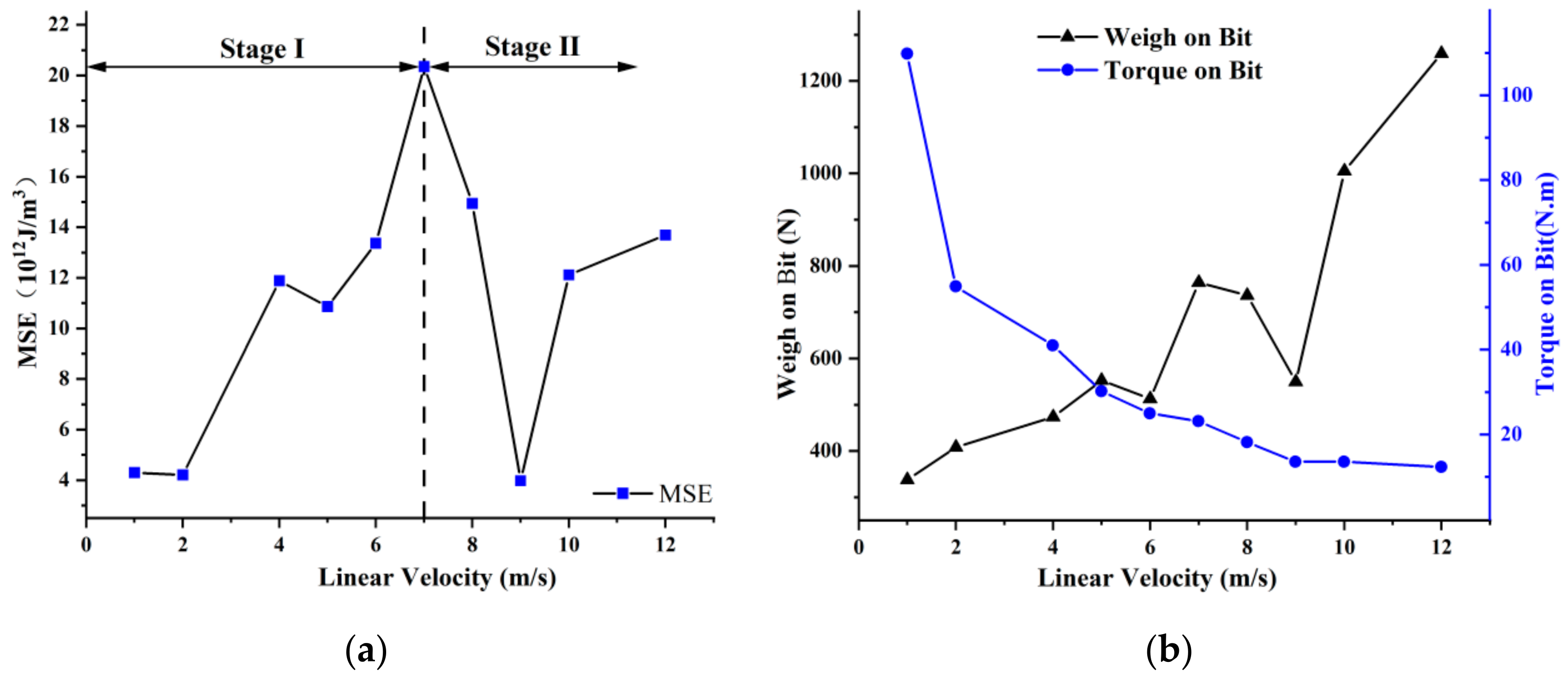
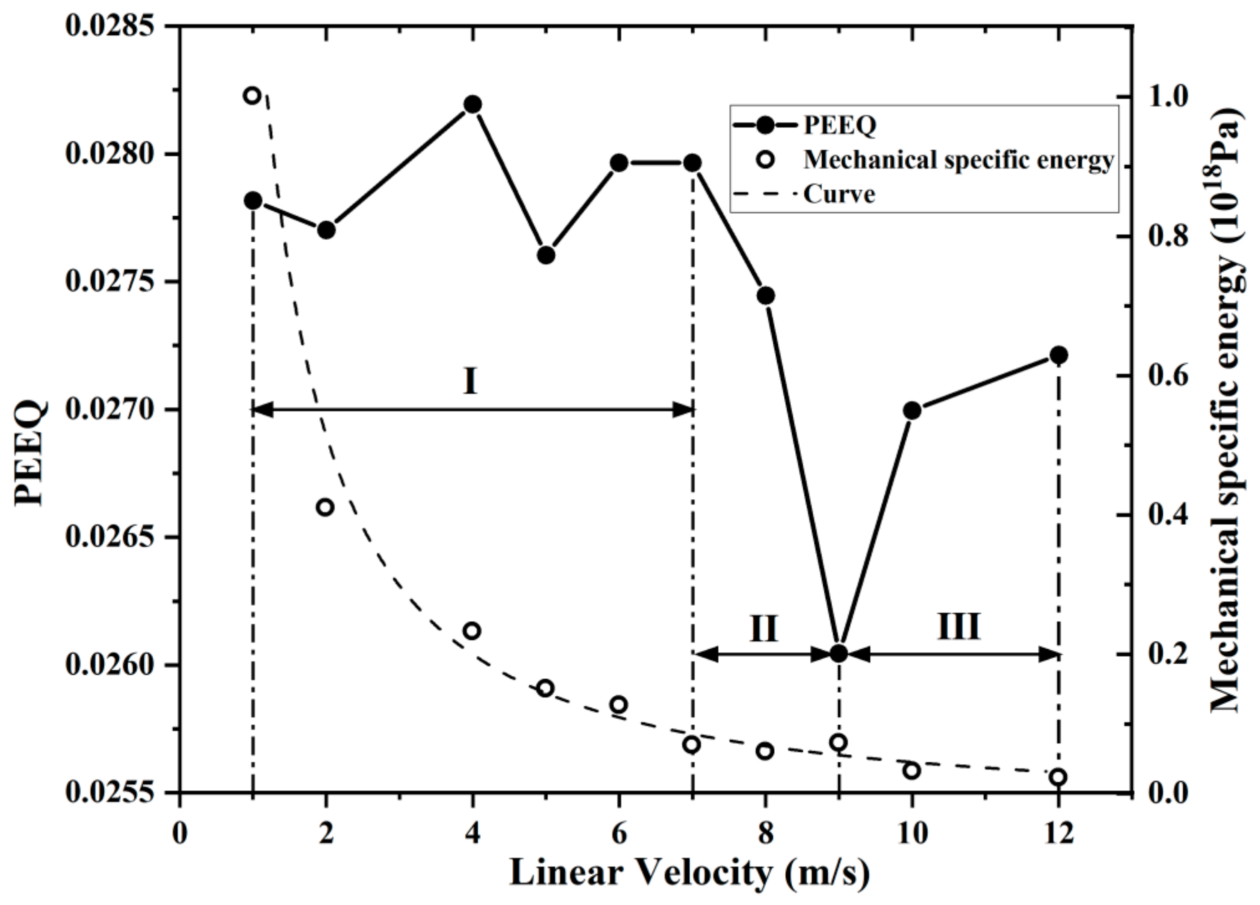
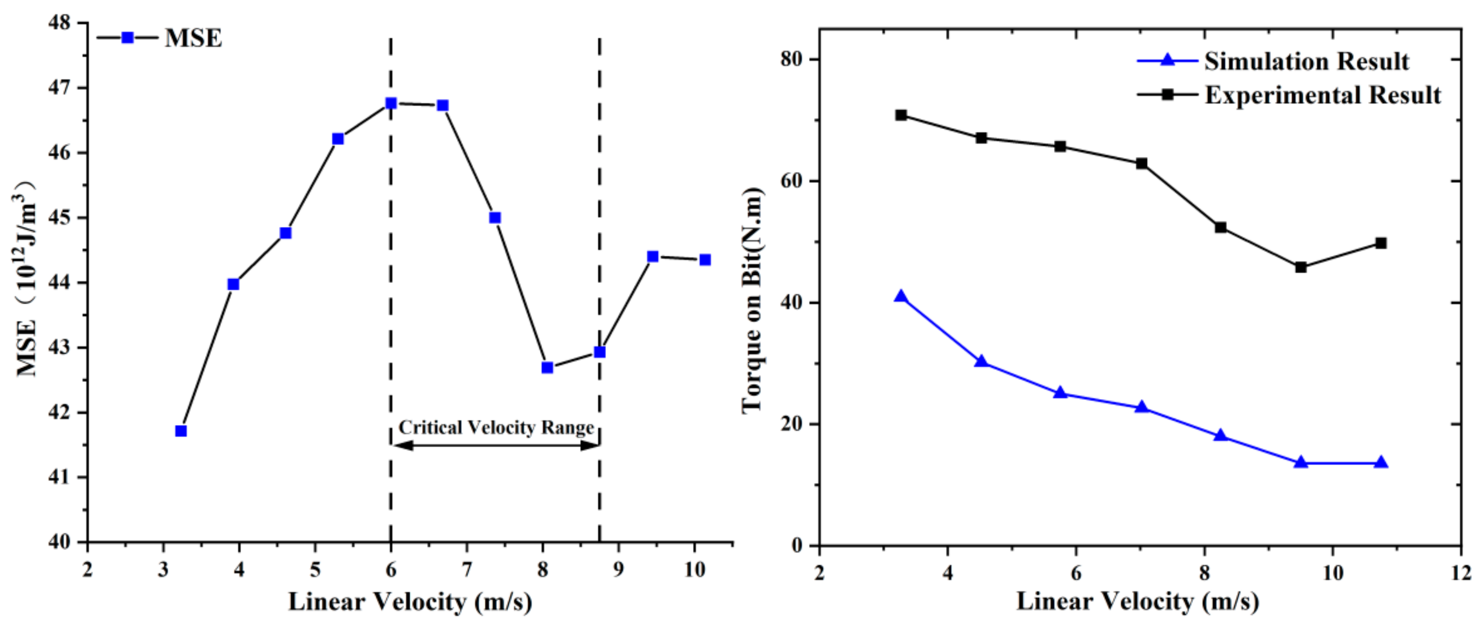
Figure 6a depicting MSE variation with drilling speed at a constant penetration rate. A preliminary analysis identifies 7 m/s as the critical speed for ultra-high-speed conditions. In the initial phase, MSE increases with speed, but a decline is observed after reaching 4 m/s, suggesting that a moderate speed increase within the conventional range can reduce MSE. However, at 5 m/s, MSE sharply rises, leading to significant energy loss, prompting many drillers to prefer lower speeds. At 7 m/s, MSE exhibits a second decline with a broader range and steeper slope than at 4 m/s. The lowest MSE occurs around 2 m/s. Beyond 9 m/s, MSE gradually stabilizes. Between 7 m/s and 9 m/s, MSE decreases rapidly with speed, aligning with findings from A. Judzis, Gao Mingyang, and others, affirming the model’s applicability. Equation (9) highlights the significant impact of drilling pressure, torque, drilling speed, drill bit radius, and speed on MSE in diamond drilling. As the simulation assumes constant drilling speed without considering bit wear, drilling pressure and torque are vital for MSE assessment. Figure 6b depicts drilling pressure and torque curves, generally increasing with speed in the conventional range, with a turning point at 6 m/s. At 7 m/s, drilling pressure reaches 22 N. In the second phase, akin to the MSE trend, drilling pressure drops to 549 N at 9 m/s, a 7.6% reduction from the average of 507 N in the first phase. The 7–9 m/s range is crucial compared to conventional speeds. Drill bit torque consistently decreases with speed, reaching a limit at 9 m/s for ultra-high-speed conditions.
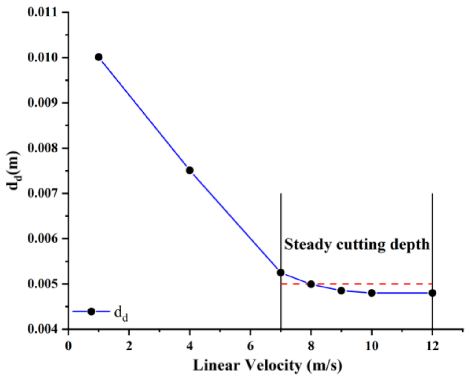
Figure 7 depicts the relationship between the diamond-specific depth of cut (dd) per revolution and speed. As the speed rises, the diamond depth of cut per revolution sharply declines. In the first phase, continuous speed growth leads to a notable drop in diamond-specific depth of cut, reducing rock volume per revolution. When correlated with Figure 6a, the decrease in diamond-specific depth of cut corresponds to an increasing MSE trend, despite a descent from 4 m/s to 5 m/s, indicating an overall MSE increase. Conventional drilling procedures show that merely increasing speed does not boost drilling efficiency; it accelerates diamond wear, reducing the entire diamond-embedded drill bit’s lifespan. Once 7 m/s is reached, the diamond-specific depth of cut per revolution stabilizes. However, explaining the substantial MSE reduction during the second phase of diamond rock breaking based solely on the angle of diamond-specific depth of cut per revolution is inadequate.

3.2. Effect of Rock Breaking Mechanism by Ultra-High Speed

Regarding the study of rock-breaking mechanisms under ultra-high speed, we primarily focused on stress S and equivalent plastic strain (PEEQ) as our key parameters [6,18,19,21,
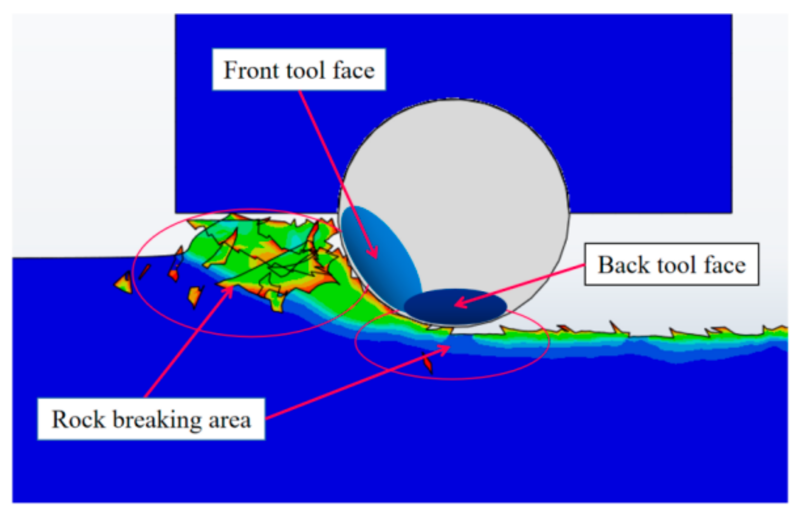
22]. Simplifying the microscopic process of diamond rock-breaking as micro-cutting, based on bit rock cutting analysis experience, we divide the bottom of the rock-breaking pit into two areas, as shown in Figure 8. The part of the rock in contact with the area in front of the diamond after penetration is termed the “front tool face”. The region in contact with the rock in front of the bit is the “back tool face” [15,16]. The rock-crushing area on the front face is the effective crushing area, where the rock undergoes crushing due to the bit’s extrusion and cutting actions. The resulting equivalent plastic strain and damage in this area are termed effective strain and damage. Conversely, the area on the rear cutter face is deemed the ineffective plastic strain and damage area.
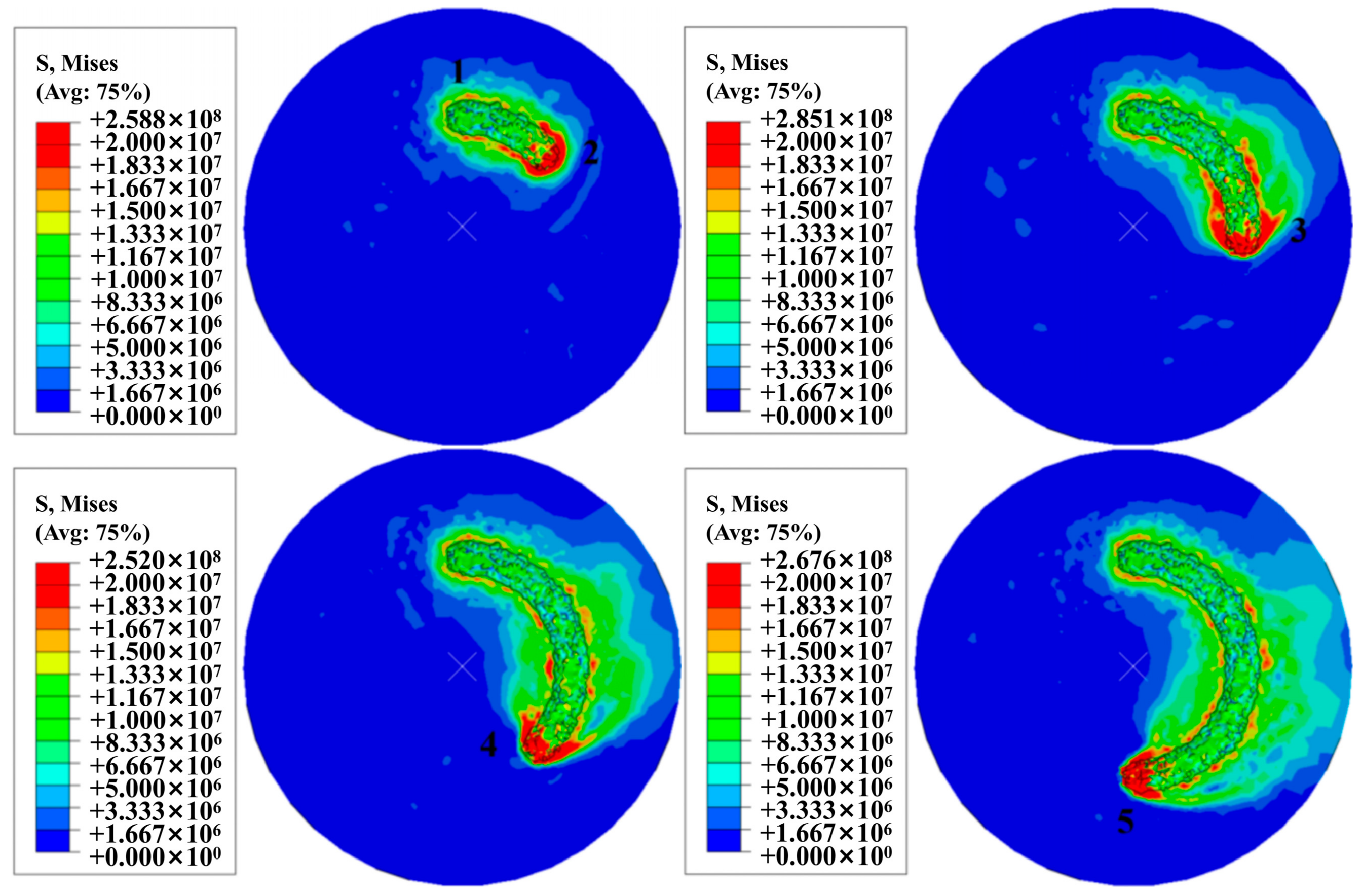
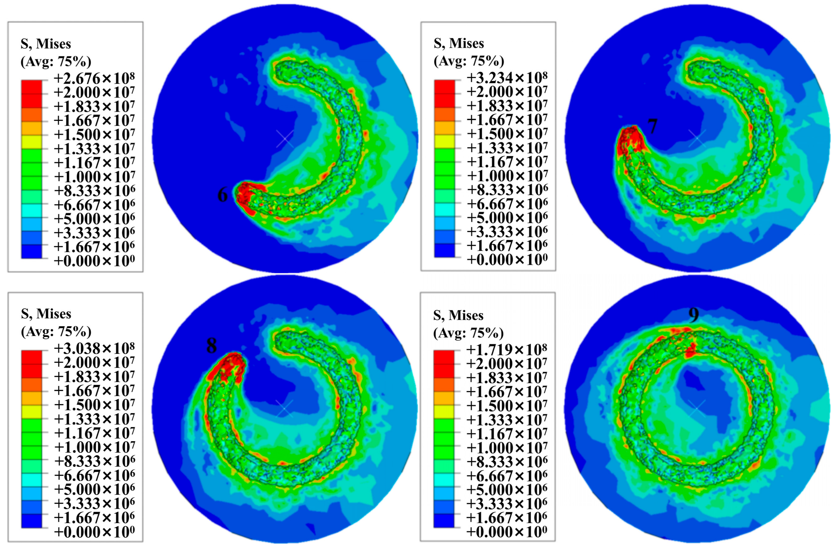
The 3D diamond rock crushing process takes into account both the vertical feed and cutting width of the diamond. Variations in diamond cutting width have a significant impact on the volume of the rock-crushing pit. Understanding how diamond width changes with different drilling speeds is crucial. Using the stress cloud map at 12 m/s as an example, we segment the diamond’s one-revolution behavior into distinct points (Figure 9). According to Equation (8), the equivalent plastic strain of the rock unit is eliminated when it matches the equivalent plastic strain at the moment of rock crushing. The diamond’s cutting process per revolution is divided into nine stages. Initially, the diamond penetrates the rock by 0.1 mm, causing no surface damage, and a crushing crater forms due to stress concentration. The rock transitions from elastic to plastic deformation, accumulating plastic strain until it matches the equivalent plastic strain unit, at which point it breaks. As the diamond progresses from point 2 to point 8, the stress cloud diagram shows significant stress concentration on both the front and back blade surfaces, diffusing stress waves and expanding the rock’s crushing pit. The pit size gradually increases with rotation until, at point 9, the stress value dramatically drops, forming a complete ring-shaped crushing pit (Figure 9). Considering the notable MSE reduction in Stage II (Figure 6a), the next section explores the energy expended by the diamond to crush a unit volume of rock per revolution and the mechanics of rock crushing to illuminate this phenomenon.
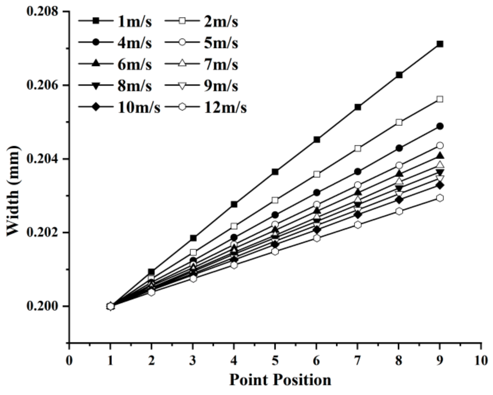
Figure 10 illustrates the variation in the contact width between the diamond and rock, represented as the rock crater width, at different rotational speeds. Initially, at point 1, the contact width is 0.2 mm. As drilling continues, the contact width increases rapidly, and this rate of increase diminishes as the rotational speed rises. Between 5 m/s and 10 m/s, the crater width remains relatively stable, with differences within a range of 0.002 mm. As the ROP remains constant, the depth of cut per revolution of the drill tooth decreases with increasing rotational speed, as depicted in Figure 7. The relationship between the volume of rock crushed per revolution of the diamond and the MSE serves as a critical basis for optimizing drill bit design. Given that different volumes of rock are crushed within the same drilling time at various RPM values, evaluating drill bit rock-crushing efficiency solely based on the volume of diamond crushed per revolution is insufficient.
By considering the curves of diamond width and cutting depth at different RPM values, the quantity of rock broken per revolution can be computed. This approach allows the calculation of the energy expended by the diamond to break a unit volume of rock over one revolution. Figure 11 displays the variation in the energy consumed by the diamond to crush a unit volume of rock per revolution at different speeds. It is evident that the specific energy of rock crushing follows a similar trend to the variation in cutting depth per revolution. Within the range of 7 m/s to 12 m/s, the specific energy of rock crushing remains relatively stable. This implies that, from the perspective of rock-crushing specific energy, further increasing the speed beyond 7 m/s may not significantly enhance rock-crushing efficiency.
To comprehensively explore the optimal speed range, we conducted an analysis of the rock’s equivalent plastic strain [18]. Figure 11 depicts the evolving curve of equivalent plastic deformation at different speeds. In the initial phase, the values of the rock’s equivalent plastic strain exhibit stable fluctuations, with minimal impact from speed increases. However, in the subsequent stage, speeds exceeding 7 m/s lead to a sharp decrease in equivalent plastic strain values, resembling the MSE trend. Reduced values of equivalent plastic strain (PEEQ) imply less plastic deformation during rock breaking, indicating a shift in the rock fragmentation mechanism. In practical drilling, achieving more brittle fracture in rocks is typically preferred. During brittle failure, rocks not only undergo plastic deformation but also experience crack propagation. The inevitability of plastic fragmentation throughout the entire rock-breaking process implies that greater energy consumption in plastic fragmentation results in lower rock-breaking efficiency. Hence, the PEEQ variation curve suggests that ultra-high-speed diamond drilling can diminish the plastic fragmentation of rocks within a specific range, offering theoretical support for optimizing drilling parameters and rock-breaking methods.
Figure 6 and Figure 11 identify a distortion point between 7 m/s and 12 m/s. Beyond 9 m/s, Mean Square Error (MSE) rises, stabilizing after 12 m/s. The PEEQ within the 9 m/s to 12 m/s curve starts climbing, reaching 0.0273 by 12 m/s. Although PEEQ increases from 7 m/s to 9 m/s, it remains significantly lower than the plastic strain values induced by conventional speed-induced rock fragmentation.
In summary, the drilling process can be divided into three stages based on the MSE and PEEQ curves. In the range of 7 m/s to 9 m/s, MSE declines, deviating from conventional drilling speeds. The MSE in Stage I (1 m/s to 7 m/s) mirrors conventional speed drilling, peaking at 7 m/s. Increased speed in conventional drilling does not enhance the efficiency of drill teeth but raises energy consumption. However, in Stage II, post 7 m/s, MSE significantly drops, consistent with high-speed metal-processing research. This supports the ‘speed valley’ concept, where surpassing conventional drilling limits causes MSE to decline, directing more energy to rock fragmentation. Defining the optimal speed range is crucial for widespread ultra-high-speed diamond drilling using various particle types for diverse rock cutting.
For the three speed intervals, stress cloud diagrams for diamond rotations at 2 m/s, 7 m/s, 9 m/s, and 12 m/s are chosen. Figure 12 illustrates the variation in maximum principal stress in rock fragmentation pits at different diamond rotation speeds. From the rock center to the outer part of the pit, speed influences the maximum principal stress, showing diverse stress states. At 2 m/s diamond rotation, the pit area is mainly under compressive stress. In Stage II, at 7 m/s, the trailing face’s contact area is predominantly under compressive stress, transitioning the rock from elastic to elastoplastic stages. Ongoing cutting expands the tensile stress area in the diamond-rock contact region, causing rock damage and plastic deformation. Ultimately, at the interface of compressive and tensile stress in the diamond–rock contact area, rock failure occurs, forming the pit. The stress cloud diagram reveals that the pit area is mainly under tensile stress, while the tooth’s leading and trailing faces are under compressive stress. At 7 m/s and 9 m/s, the rock pit is mainly under tensile stress, with continued cutting increasing tensile and compressive stress values around the pit. At the junction, a new rock fracture zone forms, and the pit continues to expand. After a single rotation, the entire rock layer is fragmented, revealing a new rock at the well’s bottom.
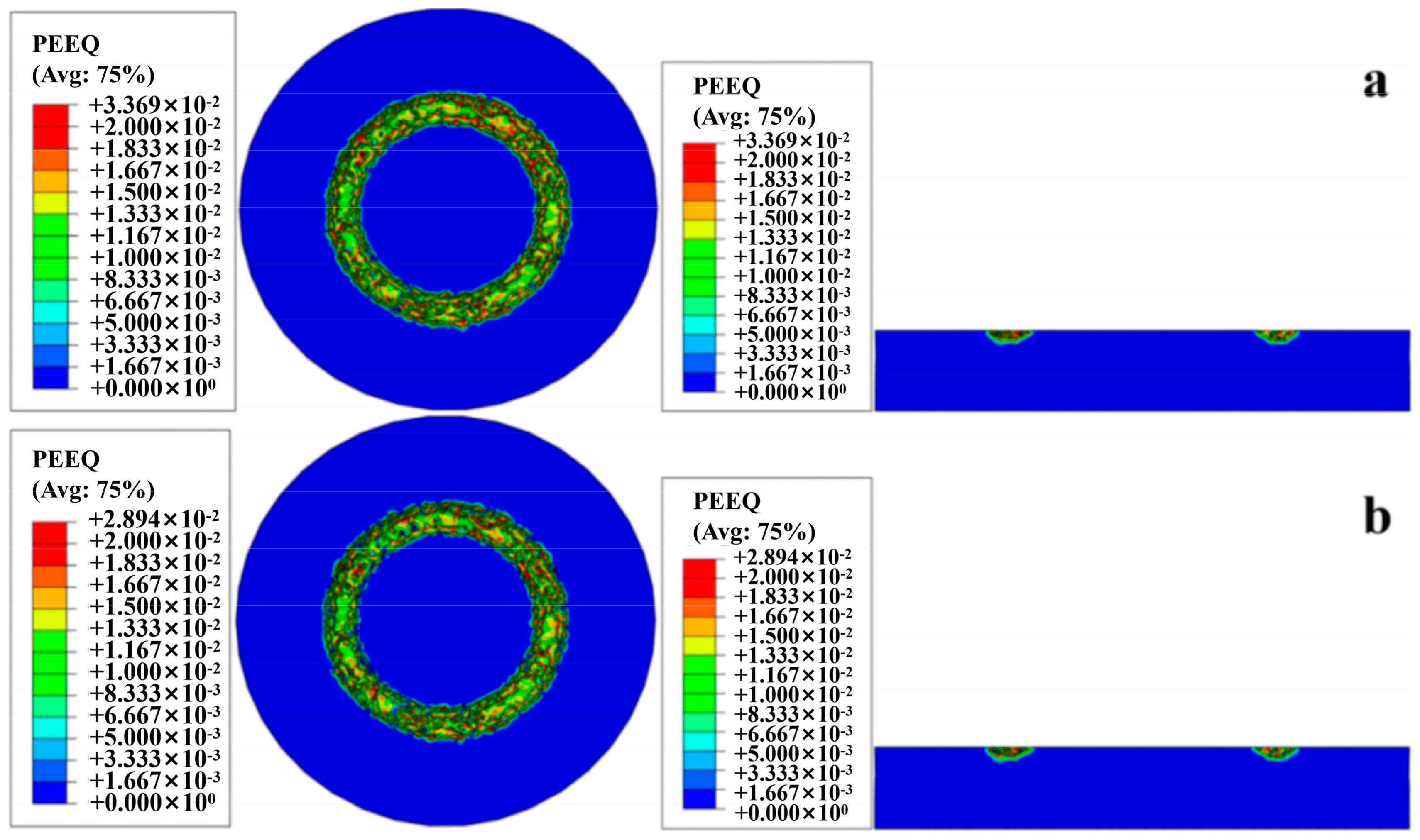
The equivalent plastic strain cloud diagram demonstrates that the rock surrounding the crushing pit has undergone residual plastic deformation (Figure 13). The equivalent plastic strain map of the rock at the bottom of the borehole is extracted from the critical speeds of stages I and II. At 9 m/s, the maximum value of equivalent plastic strain at the drill bit’s face is reduced by 12.4% compared to that at 2 m/s. Although the distribution of the residual equivalent plastic strain at the bottom of the borehole remains consistent, the residual equivalent plastic strain of the rock generally decreases in the same distribution area. By considering Figure 11 and Equation (8), we analyzed the region of equivalent plastic strain generated by the rock at the bottom of the borehole during the diamond-breaking process. The decrease in the value and distribution ratio of the residual equivalent plastic strain in the rock at the bottom of the borehole further suggests that the increase in rotational speed altered the rock’s crushing mechanism.
In summary, during the high-speed diamond rock-crushing process, the rock initially experiences elastic deformation when subjected to cutting forces beneath the diamond. Once the stress surpasses the yield stress, it enters a plastic deformation stage. With continued drilling, the equivalent plastic strain in the rock exceeds a critical value, resulting in rock fracturing (as per Equation (8)), and some rock is removed, forming debris. The newly exposed rock forms the bottom of the borehole and undergoes further diamond cutting. In the diamond-cut area and adjacent areas of the rock, compressive and tensile stress regions intersect, with tensile stress being the primary mode of rock damage. In contrast, areas farther from the diamond in the rock model remain in a compressive stress state and do not fracture [28,29].
The rock-breaking situation, concerning the diamond-cutting depth per revolution, is analyzed from the perspective of the efficiency of breaking the same volume of rock per unit time. As depicted in Figure 11, the rock-breaking specific work performed by the diamond to break the same volume of rock per unit time exhibits a decreasing trend with increasing rotational speed, eventually stabilizing after reaching 7 m/s. With increasing speed, the depth of cut per revolution of the diamond decreases due to the diamond consistently maintaining a drilling speed of 0.05 m/s. Consequently, the horizontal coordinates in Figure 11 can also represent the change in the depth of cut per revolution of the diamond. The increase in speed implies a reduction in the volume of rock fragmented per revolution of the diamond. While the volume of rock crushed per revolution decreases, the energy consumption per unit volume of rock crushed by the teeth diminishes significantly, and the crushing efficiency remains undiminished. This further underscores that increasing the rotational speed effectively enhances crushing efficiency, with the mechanism shifting when the rotational speed reaches 7 m/s. The application of ultra-high rotational speed can, thus, significantly improve crushing efficiency.
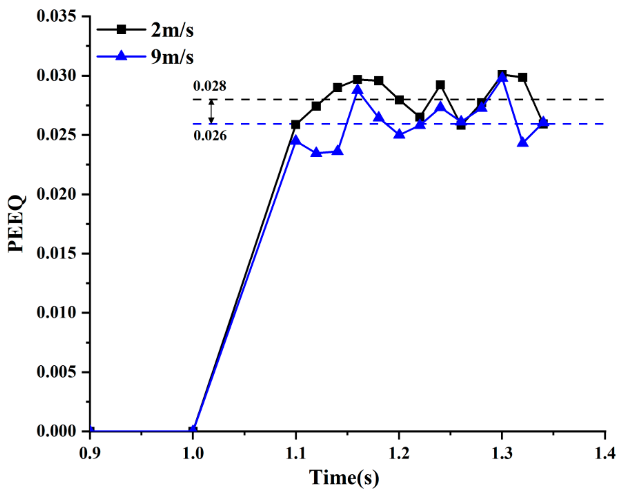
To further elucidate the impact of speed on the rock-crushing process, we delve into the equivalent plastic strain of the crushed rock. In Figure 14, we compare the equivalent plastic strain values of rock crushing under two different rotational speeds, 2 m/s and 9 m/s, using the equivalent plastic deformation curves of the diamond that contacts the rock nodes (as seen in Figure 15). The residual equivalent plastic strain of the rock under ultra-high-speed conditions is significantly reduced. Specifically, the equivalent plastic strain value of the rock fluctuates around 0.028 at 2 m/s, while the corresponding value at 9 m/s is approximately 0.026. This indicates a 7.14% reduction in equivalent plastic strain at 9 m/s compared to 2 m/s. The rationale behind this shift in the proportion of elastic–plastic damage of the rock under ultra-high-speed conditions may be attributed to the rock experiencing a higher frequency of cutting forces and elevated stress values.
In rock breaking, brittle crushing plays a pivotal role in enhancing the efficiency of drilling teeth for crushing rocks. When attempting to break the same volume of rock, ultra-high rotational speeds can significantly bolster drilling efficiency. Stage III, marked by a rotational speed of 9 m/s, stands out as the point where the equivalent plastic strain value of rock crushing reaches its minimum. This juncture can be deemed as the optimal speed for efficient rock crushing. However, as the speed exceeds 9 m/s, the equivalent plastic strain begins to exhibit an upward trend once more. Examining the variation curve of the crushing pit width at different speeds in Figure 11, we observe that the diamond-cutting width and the volume of crushed rock both decrease after the speed surpasses 9 m/s. The additional kinetic energy generated by the RPM increase does not significantly impact rock crushing; instead, more energy is diverted towards frictional energy dissipation between the rear face of the blade and the rock. Optimal speed range selection can effectively mitigate energy dissipation and elevate rock-crushing efficiency.

3.3. Effect of Varied Rotational Speed on Energy

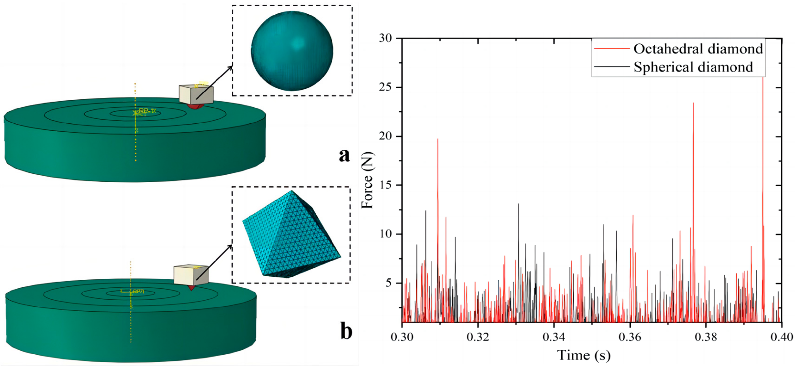
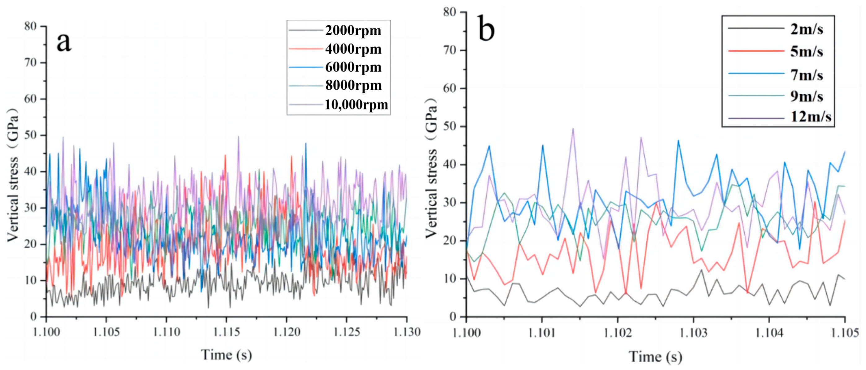
Figure 16 provides a comprehensive summary and comparison of vertical stress versus time curves for diamond at different speed intervals [30]. Initially, during the onset of cutting, the stress experiences a relatively modest increase, primarily attributable to the deformation caused by the face’s extrusion. However, as drilling advances, the diamond stress undergoes pronounced and periodic fluctuations. This fluctuation is spurred by the expanding depth and width of the diamond as it penetrates the rock, leading to a rapid surge in diamond stress. The process of the diamond crushing the rock goes hand-in-hand with stress–strain accumulation within the rock unit, persisting until the unit is ultimately eliminated. Consequently, the contact area between the diamond and the rock diminishes, precipitating a rapid drop in stress values. Subsequently, as drilling persists, the diamond face re-establishes contact with the rock surface, causing stress values to once again ascend. This cyclical process of stress fluctuation exhibits periodicity.
The peak of the cutting force increases as the speed increases and the distance between adjacent peaks decreases. The cycle time for the diamond to finish cutting and crushing the rock becomes shorter. From the previous analysis of the results of diamond drilling at high speeds, the increase in speed leads to a decrease in the depth of cut per revolution of the diamond. According to the existing research, the lower the cutting depth, the lower the plastic deformation of the rock, which leads to the plastic deformation of the rock and reduces the efficiency of rock crushing.
However, Figure 8 shows that after the rotational speed reaches 7 m/s, the diamond-cutting depth per revolution is basically stable, but the residual equivalent plastic strain value of the rock appears to be greatly reduced. This shows that the depth of cut is not the only evaluation index that affects the transformation of the elastic–plastic crushing mechanism of the rock, but that the change in rotational speed also has a great influence. In conclusion, according to the simulation results, the optimum speed range is 7 m/s–9 m/s, taking into account the diamond-cutting force, the MSE and the equivalent plastic strain value of the rock.
For a more comprehensive analysis of energy consumption in rock crushing and the distribution of different energies across various speed intervals, this paper examines the internal energy of the entire rock-crushing model and the energy consumed by drilling teeth during rock crushing from two distinct perspectives. Rock, as a complex elastic–plastic material, undergoes fractures that result from the combined influence of dissipative energy and releasable energy. Dissipative energy predominantly leads to damage and the plastic deformation of rock units, serving as the primary driving force behind the creation of new surfaces during rock fracturing. Elastic strain, on the other hand, causes elastic deformation within the rock, and energy is subsequently released when the rock is unloaded. Upon subjecting the rock to loading, two key changes occur: the formation of new surfaces and the development of internal plastic strain and damage.
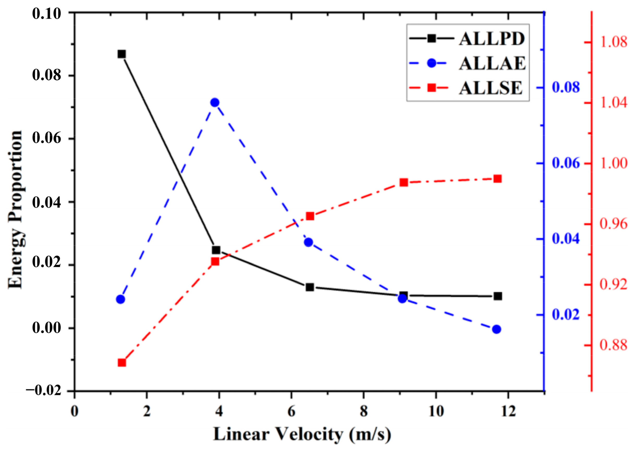
For the entire diamond rock crushing model, the total energy involved in the rock crushing process can be categorized into three components: the kinetic energy exerted by the drill bit (ALLKE), the internal energy of the rock (ALLIE), and the external work performed (ALLWK). To gain a deeper understanding of the energy distribution within the rock during the entire process, from stress–strain accumulation to reaching the damage value unit due to the action of the drill teeth, it is essential to elucidate the study of energy distribution. In ABAQUS, the internal energy (ALLIE) encompasses several aspects, including the recoverable elastic strain energy (ALLSE), energy dissipation associated with inelastic processes (ALLPD), viscoelasticity, and pseudo-strain energy (ALLAE). It is important to note that pseudo-strain energy accounts for energy stored in hourglass resistance and shear within the shell and beam units and is not part of the core system itself. However, in the simulation results of the rock-crushing process by the drill teeth, the contribution of viscoelastic energy dissipation is negligible. Figure 17 illustrates the percentage of internal energy distribution during each phase of the rock crushing process by the drill teeth at different speeds. Notably, as the rotational speed increases, the dissipation of plastic strain energy decreases significantly. Specifically, during stages I (2 m/s–7 m/s) and III, plastic energy dissipation decreases markedly and stabilizes. These results further underscore how an increase in rotational speed alters the rock-crushing mechanism, leading to a notable reduction in energy consumption during diamond rock crushing.
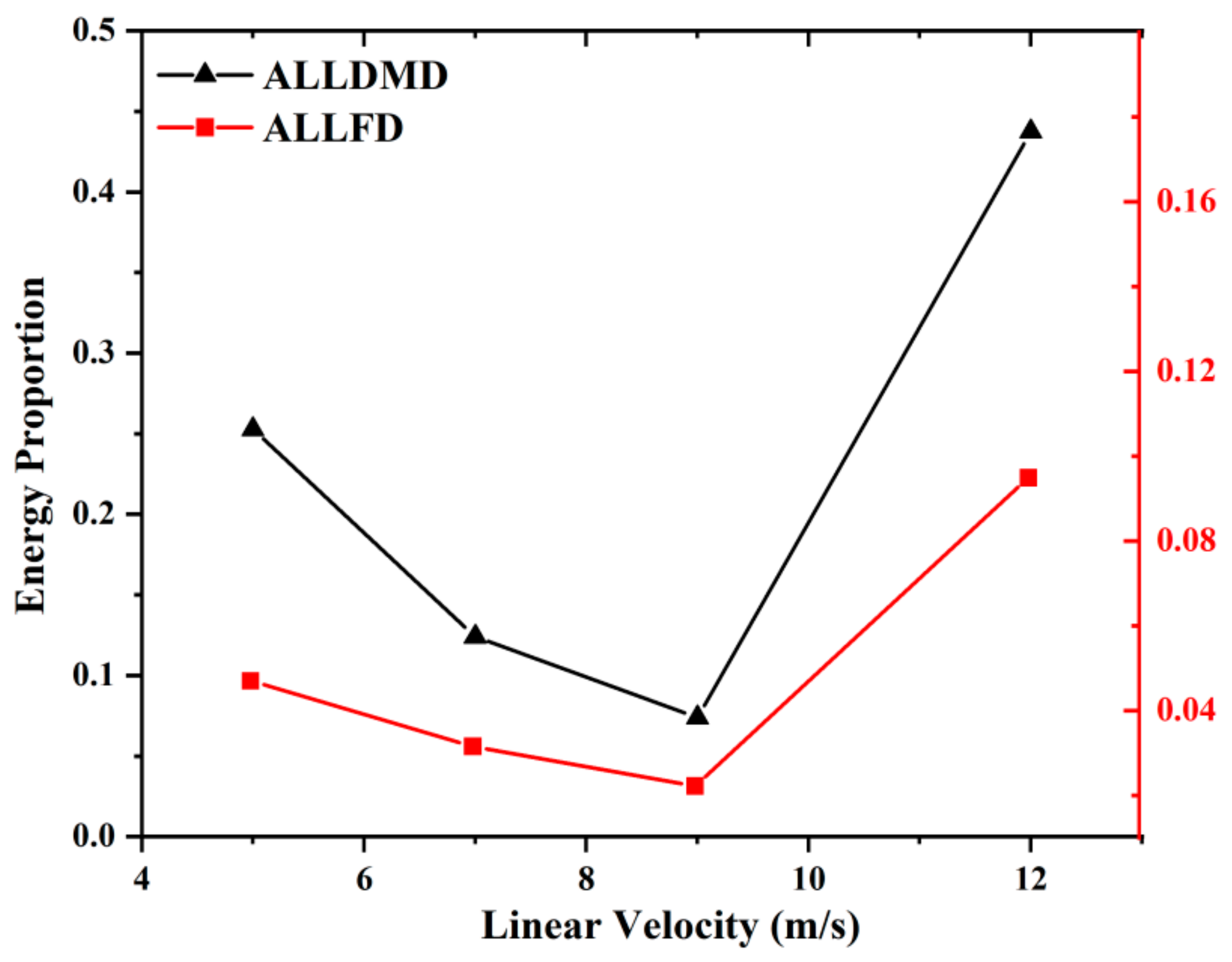
Based on existing research into the forces and energy involved in rock crushing by drill bits, it is commonly recognized that the forces and work performed by the drill bit can be broadly categorized into two components. These components encompass the work required to compress and crush the rock via the front face of the bit and the work needed for the frictional interaction between the back face of the bit and the rock. In this study, we further break down the energy dissipation during rock crushing by diamond into two distinct parts: the energy dissipated through friction (ALLFD) and the energy dissipated as a result of rock crushing and crack damage (ALLDMD). Figure 18 provides insights into the ratio of frictional energy dissipation to energy dissipation from rock damage at various speeds. During stages I and II, the trend of decreasing proportions between these two energy components closely aligns with the increase in linear velocity. This reduction in the ratio of energy spent on rock damage versus energy spent on friction suggests that, at higher rotational speeds, a larger share of energy is directed toward raising the temperature of the rock. This observation underscores that conventional speeds do not result in improved rock-breaking efficiency by the diamond. However, when the rotational speed surpasses 9 m/s, as observed in stage III, the proportion of energy allocated to rock crushing and friction increases. This shift signifies that, at ultra-high speeds, more energy is being utilized for the purpose of rock crushing. By reducing the portion of unused, ineffective work, a greater amount of energy is effectively channeled toward rock fragmentation, thereby significantly enhancing drilling efficiency.
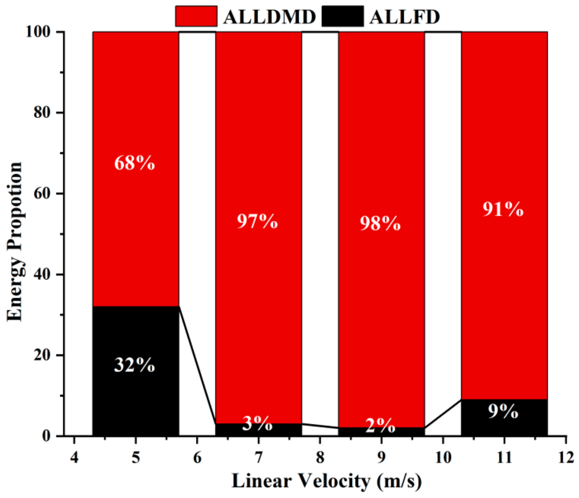
Considering both Figure 18 and Figure 19, it becomes evident that the primary contributor to energy consumption during rock crushing is the energy expended in the process of rock damage, while the fraction associated with friction energy consumption remains relatively minor. At 5 m/s, friction energy consumption makes up 32% of the total energy consumption. However, within the speed range of 7–9 m/s (corresponding to stage II), friction energy consumption is notably reduced when compared to stage I. Subsequently, after reaching 9 m/s, friction energy consumption gradually increases. These observations lead us to conclude that the optimal rotational speed interval lies between 7–9 m/s.

4. Experimental Verification

To verify the test effect of the ultra-high-speed diamond drilling technology, a drilling experimental device was used, as shown in Figure 20. The rock used in the tests was marble. The drilling parameters were designed as follows: the range of the rotational speed was approximately 3 m/s–10 m/s and the WOB was 12N. We conducted drilling experiments with impregnated diamond bits at various speeds. The results indicate that, as the speed increases, a critical speed becomes apparent, and there is also an upper speed limit, as shown in Figure 21. During the experiment, the test machine adjusts rotational speed and drilling pressure, with an external oscilloscope recording real-time torque changes and drilling time. After the experiment, we measured groove dimensions on the rock’s surface, vital for calculating ROP and MSE, examining the appearance of rock cuttings through the use of the EM-30 Plus scanning electron microscope.
Figure 21 presents the data obtained at a drilling pressure of 12N. Compared with the simulation results, MSE and TOB exhibit a generally consistent variation with speed, and a critical speed range is evident. This further confirms the accuracy of the simulation. There is a speed limit in the ultra-high-speed diamond drilling condition.
SEM images capturing the morphology of cuttings were obtained at drilling pressures of 12N and rotational speeds of 4 m/s and 8 m/s, separately. Figure 22 illustrates the particle size distribution of cuttings at these two rotational speeds. Across all speeds, cuttings of varying sizes are generated, with smaller-sized cuttings predominantly taking the form of powder. However, at the higher rotational speed of 8 m/s, the size of the cuttings notably increases, and there is a higher proportion of larger-sized cuttings. In the images, cuttings exhibit diverse morphologies beyond the powdery form, including flake-like or chunk-like shapes. This suggests that an increase in rotational speed at the same drilling pressure can significantly modify the rock fragmentation mechanism, leading to a greater degree of brittle fracture.

5. Conclusions

In this study, we investigated the critical speed challenge in ultra-high-speed diamond drilling through nonlinear dynamic simulations and experiments. Using marble as an example, we revealed the differences in rock fragmentation mechanisms between ultra-high-speed diamond drilling and traditional methods. Beyond a linear velocity of 7 m/s, WOB decreased, while MSE decreased, maintaining a stable cutting depth per diamond revolution. The equivalent plastic strain in rock fragmentation pits dropped by 7.14% compared to conventional speeds. Beyond 9 m/s, both MSE and PEEQ increased. Another viable speed range (7 m/s–9 m/s) was identified, effectively reducing MSE and enhancing rock fragmentation efficiency. However, there is a speed limit within this range, and further speed increases do not enhance drilling efficiency. Comparative analysis of rock fragmentation energy distribution under conventional and ultra-high-speed conditions revealed that the efficiency gain with ultra-high-speed diamond drilling within the critical speed range is achieved by altering the rock fragmentation mode. Notably, rock fragmentation transitions from mainly plastic deformation to predominantly brittle fracture. The ongoing advancement of this technology extends beyond the confines of marble, with future endeavors geared towards testing a broader spectrum of rocks with higher levels of hardness. This exploration aims to introduce novel paradigms to the realm of deep drilling, with a focus on enhancing drilling depth, maintaining or accelerating drilling speeds, and reducing energy consumption, thus holding substantial academic significance.

Author Contributions

Conceptualization, Y.L. and K.Z.; methodology, Y.L. and K.Z.; software, Y.L. and K.Z. and Y.W.; validation, Y.L. and K.Z.; formal analysis, Y.L. and K.Z.; investigation, Y.L. and K.Z.; resources, K.Z.; data curation, Y.L. and K.Z.; writing—original draft preparation, Y.L. and K.Z.; writing—review and editing, Y.L. and K.Z. and Y.W.; visualization, Y.L. and K.Z.; supervision, K.Z.; project administration, K.Z.; funding acquisition, K.Z.; All authors have read and agreed to the published version of the manuscript.

Funding

This work is supported by the National Natural Science Foundation of China (Nos. 42202346) and Special Fund for Scientific Research of Shandong Bureau of Coal Geology (No. 2023-5 and No. 2022-33).

Data Availability Statement

The original contributions presented in the study are included in the article, further inquiries can be directed to the corresponding author.

Conflicts of Interest

The authors declare no conflicts of interest.

References

  1. Black, A.; Judzis, A. Smaller Footprint Drilling System for Deep and Hard Rock Environments; Feasibility of Ultra-High Speed Diamond Drilling; Technical Progress Report; U.S. Department of Energy Office of Scientific and Technical Information: Oak Ridge, TN, USA, 2004. [CrossRef]
  2. Judzis, A.; Black, A.; Robertson, H. Smaller Footprint Drilling System for Deep and Hard Rock Environments; Feasibility of Ultra-High-Speed Diamond Drilling; Technical Report: 2006; U.S. Department of Energy Office of Scientific and Technical Information: Oak Ridge, TN, USA, 2006. [CrossRef]
  3. Judzis, A.; Boucher, M.; McCammon, J.; Black, A.D. Investigation of Smaller-Footprint Drilling System; Ultrahigh-Rotary-Speed Diamond Drilling Has Potential for Reduced Energy Requirements. In Proceedings of the IADC/SPE Drilling Conference, Miami, FL, USA, 21–23 February 2006. [Google Scholar]
  4. Judzis, A.; Black, A.; Robertson, H. Smaller Footprint Drilling System for Deep and Hard Rock Environments Feasibility of Ultra-High-Speed Diamond Drilling; Phase 1 Final Report; TerraTek, Inc.: Salt Lake City, UT, USA, 2007. [Google Scholar] [CrossRef]
  5. TerraTek. Smaller Footprint Drilling System for Deep and Hard Rock Environments Feasibility of Ultra-High-Speed Diamond Drilling. Final Report. 2010. Available online: https://netl.doe.gov/files/oil-gas/NT15401_FinalReport.pdf (accessed on 10 April 2024).
  6. Gao, M.Y.; Zhang, K.; Zhou, Q.; Zhou, H.F.; Liu, B.L.; Zheng, G.J. Numerical investigations on the effect of ultra-high cutting speed on the cutting heat and rock-breaking performance of a single cutter. J. Pet. Sci. Eng. 2020, 190, 107120. [Google Scholar] [CrossRef]
  7. Bone, G.; Jamerson, C.; Klassen, J.; Gray, J.; Valliyappan, S.; Baker, R.; Turner, K.; Parra, M. Maximizing BHA Durability/Reliability: Turbodrill/Impregnated Bit Significantly Reduces Drilling Time in Granite Wash Laterals. In Proceedings of the SPE/IADC Drilling Conference, Amsterdam, The Netherlands, 5–7 March 2013. [Google Scholar] [CrossRef]
  8. Carrillo, G.; Farid, U.; Albrecht, M.; Cook, P.; Feroze, N.; Nevlud, K. Innovative Solution for Drilling Pre-Khuff Formations in Saudi Arabia Utilizing Turbodrill and Impregnated Bits. In Proceedings of the SPE Middle East Oil and Gas Show and Conference, Manama, Bahrain, 15–18 March 2009. [Google Scholar] [CrossRef]
  9. Fierro, M.; Atencio, N.; Solano, R.; Varela, R.; Iturrizaga, F.; Toribio, L.; Tufano, A.; Guzman, F. Finding the Breakeven Point of Diamond Impregnated Bit Wear in Turbodrill Applications. In Proceedings of the OTC Brasil, Rio de Janeiro, Brazil, 27–29 October 2015. [Google Scholar] [CrossRef]
  10. Langille, P.; Deen, A.; Klassen, J. Minimizing Risks, Maximizing On-Bottom Drilling Time: Turbodrilling with Impregnated Bits Improves Efficiency and Circumvents Trouble Time, Southern Oklahoma. In Proceedings of the SPE/IADC Drilling Conference and Exhibition, Amsterdam, The Netherlands, 17–19 March 2009. [Google Scholar] [CrossRef]
  11. Murillo, R.; Rangel, F.G.; Melo, E.; Gonzalez, O.L.; Romero, D.A.; Beltran, D. Turbodrilling System and Diamond-Impregnated Bit Saved Three Trips in a Hard Carbonate Reservoir. In Proceedings of the SPE Latin America and Caribbean Mature Fields Symposium, Salvador, Bahia, Brazil, 15–16 March 2017. [Google Scholar] [CrossRef]
  12. Pantoja, R.; Britto, G.; Buzzá, J.; Vieira, A.M.; Laroca, F.; Appelshaeuser, G. Pioneer Turbodrilling With 16 ½” Impregnated Bit in Deep Pre-Salt Well in Santos Basin. In Proceeding of the SPE/IADC Drilling Conference and Exhibition, London, UK, 17–19 March 2015. [Google Scholar] [CrossRef]
  13. Varela, R.; Guzman, F.; Cruz, D.; Atencio, N.; Iturrizaga, F.; May, R.; Solano, R.; Perez, R. First Application of Turbodrill and Hybrid Bit to Optimize Drilling Times in Cretaceous Formations with High Chert Content in Mexico South Region. In Proceeding of the IADC/SPE Drilling Conference and Exhibition, Fort Worth, TX, USA, 4–6 March 2014. [Google Scholar] [CrossRef]
  14. Franca, L.F.P.; Mostofi, M.; Richard, T. Interface laws for impregnated diamond tools for a given state of wear. Int. J. Rock Mech. Min. Sci. 2015, 73, 184–193. [Google Scholar] [CrossRef]
  15. Detournay, E.; Defourny, P. A Phenomenological model for the drilling acttion of drag bits. Int. J. Rock Mech. Min. Sci. Geomech. Abstr. 1992, 29, 13–23. [Google Scholar] [CrossRef]
  16. Detournay, E.; Richard, T.; Shepherd, M. Drilling response of drag bits: Theory and experiment. Int. J. Rock Mech. Min. Sci. 2008, 45, 1347–1360. [Google Scholar] [CrossRef]
  17. Mostofi, M.; Richard, T.; Franca, L.; Yalamanchi, S. Wear response of impregnated diamond bits. Wear 2018, 410, 34–42. [Google Scholar] [CrossRef]
  18. Jian, H.; Bo, Z.; Yuhang, H.; Xudong, W.; Liqin, Q.; Chengyu, X.; Xianzhong, Y. Numerical study of rock-breaking mechanism in hard rock with full PDC bit model in compound impact drilling. Energy Rep. 2023, 9, 3896–3909. [Google Scholar] [CrossRef]
  19. He, W.H.; Zhang, R.Q.; Liu, L.; Chen, Z.L.; Shi, H.Z.; Huang, Z.W.; Xiong, C.; Li, X.; Sun, J.M.; Hu, C.T. Numerical simulation of rock-breaking mechanisms by triple-ridged PDC cutter in hard rocks. Geoenergy Sci. Eng. 2023, 229, 212148. [Google Scholar] [CrossRef]
  20. Wu, K.H.; Ye, Z.W. The Numerical Research on Rock Breaking and Rising Mechanism of Rotary-Percussive Drilling. Arab. J. Sci. Eng. 2019, 44, 10561–10580. [Google Scholar] [CrossRef]
  21. Yang, Y.X.; Zhang, C.L.; Lin, M.; Chen, L. Research on rock-breaking mechanism of cross-cutting PDC bit. J. Pet. Sci. Eng. 2018, 161, 657–666. [Google Scholar] [CrossRef]
  22. Zhong, Z.-H. Finite Element Procedures for Contact-Impact Problems; Oxford University Press: Oxford, UK, 1993. [Google Scholar] [CrossRef]
  23. Alejano, L.R.; Bobet, A. Drucker-Prager Criterion. Rock Mech. Rock Eng. 2012, 45, 995–999. [Google Scholar] [CrossRef]
  24. Liu, W.J.; Qian, X.D.; Li, T.; Zhou, Y.L.; Zhu, X.H. Investigation of the tool-rock interaction using Drucker-Prager failure criterion. J. Pet. Sci. Eng. 2019, 173, 269–278. [Google Scholar] [CrossRef]
  25. Yang, Y.D.; Liao, H.L.; Niu, J.L.; Wang, Z.; Chen, J.H. Three-dimensional simulation of rock breaking efficiency under various impact drilling loads. Arab. J. Geosci. 2020, 13, 444. [Google Scholar] [CrossRef]
  26. Dong, Z.X.; Zhang, H.; Li, J.; Zhang, K.S.; Ou, Y.Y.; Lu, Z.Y.; Shi, J.G. A Method for Evaluating the Rock Breaking Efficiency of Cutters and Optimizing the PDC Cutter Profile-A Study of Igneous Rock Formations in Shunbei Oilfield. Energies 2022, 15, 6686. [Google Scholar] [CrossRef]
  27. Teale, R. The concept of specific energy in rock drilling. Int. J. Rock Mech. Min. Sci. Geomech. Abstr. 1965, 2, 57–73. [Google Scholar] [CrossRef]
  28. Jaime, M.C.; Zhou, Y.N.; Lin, J.S.; Gamwo, I.K. Finite element modeling of rock cutting and its fragmentation process. Int. J. Rock Mech. Min. Sci. 2015, 80, 137–146. [Google Scholar] [CrossRef]
  29. Zhou, Y.N.; Lin, J.S. On the critical failure mode transition depth for rock cutting. Int. J. Rock Mech. Min. Sci. 2013, 62, 131–137. [Google Scholar] [CrossRef]
  30. Zhang, Z.Z.; Zhao, D.J.; Zhao, Y.; Gao, K.; Zhang, C.S.; Lü, X.S. 3D numerical simulation study of rock breaking of the wavy PDC cutter and field verification. J. Pet. Sci. Eng. 2021, 203, 108578. [Google Scholar] [CrossRef]
Figure 1. Development history of ultra-high-speed diamond drilling.
Applsci 14 03403 g001
Figure 2. Schematic diagram of ID bit rotary drilling technology.
Applsci 14 03403 g002
Figure 3. ID bit and rock model.
Applsci 14 03403 g003
Figure 4. Verification of the influence of diamond shape on model accuracy. (a)Spherical diamond; (b) Octahedral diamond.
Applsci 14 03403 g004
Figure 5. Mesh and boundary conditions.
Applsci 14 03403 g005
Figure 6. (a) MSE change curve with speed; (b) torque curve of weight on bit with speed.
Applsci 14 03403 g006
Figure 7. Curve of cutting depth per revolution with speed.
Applsci 14 03403 g007
Figure 8. Schematic diagram of rock-breaking process of micro-cutting with ID bits.
Applsci 14 03403 g008
Figure 9. Schematic diagram of cutting process points.
Applsci 14 03403 g009aApplsci 14 03403 g009b
Figure 10. Width of crushing pit at different points per revolution.
Applsci 14 03403 g010
Figure 11. PEEQ and rock-breaking specific work per revolution change curve with speed.
Applsci 14 03403 g011
Figure 12. Fracture pit-induced rock stress cloud in varied-speed diamond rock breaking: (a) 2 m/s; (b) 7 m/s; (c) 9 m/s; (d) 12 m/s.
Applsci 14 03403 g012
Figure 13. Nephogram of equivalent plastic strain under different speed: (a) equivalent plastic strain at 2 m/s; (b) equivalent plastic strain at 9 m/s.
Applsci 14 03403 g013
Figure 14. Equivalent plastic strain of rock under ultra-high rotational speed and conventional rotational speed.
Applsci 14 03403 g014
Figure 15. Node number of broken area.
Applsci 14 03403 g015
Figure 16. Relationship between cutting force and time: (a) 1.1 s–1.130 s; (b) 1.1 s–1.105 s.
Applsci 14 03403 g016
Figure 17. Internal energy distribution during diamond crushing.
Applsci 14 03403 g017
Figure 18. Ratio of rock-crushing energy and friction energy consumption.
Applsci 14 03403 g018
Figure 19. Rock-breaking energy and friction energy distribution.
Applsci 14 03403 g019
Figure 20. Experimental devices. (a) ultra-high-speed diamond drilling test bench; (b) structure diagram; (c) oscilloscope.
Applsci 14 03403 g020
Figure 21. The curve of MSE and TOB with speed variation under a WOB of 12N.
Applsci 14 03403 g021
Figure 22. Particle size distribution chart of marble cuttings at different speeds: (a) 4 m/s; (b) 8 m/s.
Applsci 14 03403 g022
Table 1. Physical and mechanical properties of the material.
Density (kg/m3)Young’s Modulus (GPa)Poisson’s RatioAngle of Friction (°)Flow Stress
Ratio
Dilation Angle (°)Yield Stress for DP
Hardening (MPa)
Fracture Strain
Diamond35108900.07
Marble2650400.2534.87120.3300.06
Disclaimer/Publisher’s Note: The statements, opinions and data contained in all publications are solely those of the individual author(s) and contributor(s) and not of MDPI and/or the editor(s). MDPI and/or the editor(s) disclaim responsibility for any injury to people or property resulting from any ideas, methods, instructions or products referred to in the content.

