Abstract
The reasonable construction state of a cable-stayed bridge refers to the state achieved after construction is carried out according to a specific sequence of procedures, leading to the reasonable completion status the bridge. The corresponding construction states at each stage are considered as part of the reasonable construction state. For the optimization of the construction state of cable-stayed bridges with steel box girders, a method combining a multi-objective programming algorithm with a forward iteration method is proposed to determine a reasonable construction state based on the structural characteristics and optimization principles of such bridges. First, a multi-objective programming model was established, taking the bending moments of the main girder and pylon, as well as cable forces, as objective functions. The weighted square sum method, a type of evaluation function method, was then employed to convert the multi-objective programming model into an unconstrained single-objective quadratic programming model. Subsequently, the damped Newton method was utilized to solve the quadratic programming problem. By integrating this algorithm with the forward iteration method, the reasonable construction state of a large-span and double-tower steel box girder cable-stayed bridge was optimized. The influence of different objective functions on the optimization results was analyzed. The findings demonstrate that the proposed method produces a smooth structural configuration under the optimized construction state, with internal forces and normal stresses within a reasonable range. In the completed state derived from this construction state, internal forces, normal stresses, and cable forces are uniformly distributed, while the reactions at transition piers and auxiliary piers exhibit sufficient pressure reserves. The structural state under dead load achieved through this method closely aligns with the desired reasonable completed state.
1. Introduction
The steel box girder cable-stayed bridge has become one of the fastest-growing and most competitive bridge types in modern bridge engineering, owing to its aesthetic appeal, simplicity, and impressive spanning capabilities. In recent years, as the use of steel box girder cable-stayed bridges has expanded, their span lengths have increased, and the structural systems have become more diverse. Consequently, the optimization of cable-stayed forces has emerged as a critical issue in the design and computational analysis of these bridges [,,]. The optimization of cable-stayed bridges is typically divided into two main processes: the optimization of the cable-stay configuration and the optimization of the initial construction tension. First, the desired bridge state is used to determine the reasonable cable force for the bridge. Next, this reasonable cable force is set as the control target, and based on the actual construction process, the appropriate construction tension is determined to ensure proper construction control [,].
The reasonable construction state of a cable-stayed bridge refers to the state achieved after construction is carried out according to a specific sequence of procedures, leading to the reasonable completion status the bridge. The corresponding construction states at each stage are considered as part of the reasonable construction state. The main control parameters during the construction process are the cable tension during the stay cable installation and the positioning elevation of the main girder segments. Since the positioning elevation of the main girder segments in a cable-stayed bridge is influenced by the stay cable forces, the optimization problem of the reasonable construction state of the cable-stayed bridge is essentially transformed into the problem of optimizing the cable force.
In recent years, numerous researchers have conducted extensive studies on the optimization of cable forces in stayed-cable bridges during their rational construction states, proposing various optimization methods for determining reasonable construction cable-stayed bridges [,,]. Commonly used methods for optimizing cable forces include the forward analysis method, the inverted disassembly method, the forward-inverted disassembly iterative method, the forward iterative method, and the stress-free state method [,,,].
Chen et al. [] optimized the initial cable forces of prestressed concrete cable-stayed bridges using the force equilibrium method, which can take into account the effect of additional moments caused by vertical profile of the deck. Fabbrocino et al. [] proposed an optimization approach for cable-stayed bridges by refining the bending moment distribution of the main girder composites to achieve the optimal bridge-forming cable forces. The results demonstrated that this method effectively brought the structure to a state of self-equilibrium stress and proved suitable for optimizing cable forces during both dynamic and construction phases. Martins et al. [] considered changes in structural internal forces and lineaments due to construction sequencing and concrete time effects, and evaluated the response of the structure to changes in design variables through sensitivity analysis. Chen et al. [] addressed the initial tension during the construction stage through an iterative process utilizing a first-order optimization algorithm, with bending strain energy as the objective function. Sung et al. [] realized the optimization of cable forces of cable-stayed bridges in the construction process based on the theory of minimum strain energy, taking the total strain energy of the bridge as the objective function. Baldomir et al. [] successfully optimized the cross-sectional area of stay cables by considering factors such as cable stress and bridge deck displacement. Lonetti et al. [] developed an optimization design method for the cable forces and cross-sectional areas of a hybrid cable-stayed bridge during its construction phase, based on finite element numerical models and iterative computational methods. In addition, numerous advanced intelligent optimization algorithms have been increasingly applied to the optimization of cable forces in cable-stayed bridges to achieve reasonable construction states [,,].
In addition to optimizing cable forces in cable-stayed bridges, the assessment of cable forces control during both the construction and lifespan phases of bridges has also been a subject of extensive research. Li et al. [] and Matos et al. [] conducted studies on the condition assessment of cable-stayed bridges, leading to several valuable conclusions. Additionally, the stability performance of stay cables has been another key area of research. Madrazo-Aguirre et al. [,] and Wu et al. [] conducted extensive studies on the stability of stay cables, focusing on their dynamic characteristics and the parameters influencing stability. Their numerical investigations yielded several valuable conclusions.
However, existing traditional methods for optimizing the reasonable construction state of cable-stayed bridges still have certain limitations: Due to the effects of structural system transformations, concrete shrinkage and creep, and geometric nonlinearities, the calculation results from the inverted disassembly method and the forward analysis method often exhibit great difference. Although the forward-inverted disassembly iterative method can account for these factors, including structural system transformations, concrete shrinkage and creep, and geometric nonlinearities, it requires complex iterative calculations using both the forward-inverted disassembly iterative methods. Therefore, there is a need to explore more appropriate optimization objectives and more efficient optimization techniques that align with the structural characteristics and construction methods of large-span cable-stayed bridges with dense cable-stayed steel box girders, in order to determine the reasonable construction state for this type of bridge.
A novel optimization method for determining the reasonable construction state of cable-stayed bridges is proposed in this paper. Firstly, the principle of determining the reasonable construction state of steel box girder cable-stayed bridge is clarified. The problem of determining the reasonable construction state of steel box girder cable-stayed bridge is then formulated as a multi-objective optimization model and solved sequentially using the weighted sum method within the evaluation function framework, followed by the damped Newton method to address unconstrained single-objective optimization problems. To validate the effectiveness of this method, it is applied to optimize the construction state of a large-span and double-tower steel box girder cable-stayed bridge, integrating it with the orthotropic iterative finite element method.
2. Introduction to Optimized Method
2.1. Optimization Principles
In determining the reasonable construction state for a cable-stayed bridge with a steel box girder, the following principles should be observed: (1) the normal stress on the girder, pylon, and stay cables should not exceed limit values under specified safety factors, with fewer cross-sections approaching these limits being preferable; (2) the shapes of the girder and pylon should remain within reasonable limits throughout the construction process; (3) cable tensioning operations should be minimized, and adjustments to cable forces should be convenient and feasible; (4) the completed state should conform to the target design parameters for the bridge’s final state.
2.2. Multi-Objective Programming Model for Cable Force Optimization
The optimization of cable forces in cable-stayed bridges falls under the category of multi-objective programming model optimization. Multi-objective programming models primarily consist of several key components: selection of design variables, selection of optimization objectives, and establishment of the optimization model. These components are introduced first.
2.2.1. Design Variables
Define the adjustment amounts of cable tensions during the forward-iteration process as design variables. Given that the entire bridge consists of n pairs of cables, the vector form is as follows:
2.2.2. Optimization Objectives
Cable-stayed bridges belong to the category of complex bridge systems. Typically, they form a triangular structure through the interaction between the stay cables, pylon, and girder to support loads. The main girder primarily resists bending moments and compression forces, while the stay cables are subjected to tensile forces. The bridge pylon mainly bears compressive forces. Figure 1 provides a typical force diagram of a cable-stayed bridge.
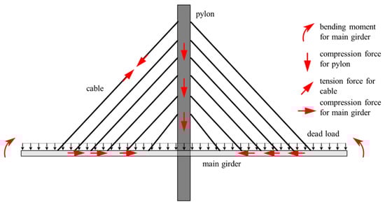
Figure 1.
Typical force diagram of a cable-stayed bridge.
Based on the deformation and mechanical characteristics of a cable-stayed bridge with a steel box girder during construction, the vertical displacement for girder and the horizontal displacement for pylon (where l represents the total number of nodes of the girder and pylon), bending moment (where m the total number of elements of girder and pylon), and cable force under dead load can be taken as control parameters. If the target values of each control parameter in the reasonable completed state are , , and , then the differences between the current state and the reasonable completed state can be calculated using the forward-iteration method. The vector form of these differences is as follows:
where M0, δ0, and T0 represent the vector of the bending moment, the displacement (vertical displacement for the girder and the horizontal displacement for the pylon) vector of the girder and pylon, and the cable force under reasonable completed state, respectively. M, δ, and T represent the vectors of the bending moment, displacements of the girder and pylon, and cable forces under the current state as calculated by the forward-iteration method. ∆M, ∆δ, and ∆T represent the difference vectors of bending moments, displacements of the girder and pylon, and cable force, respectively, between the reasonable completed state and the current state.
The basic idea of this method is to minimize the difference of each control parameter’s target value and its current state. Based on the concept of influence matrix, the optimization objectives can be formulated as follows:
where , , and represent the influence matrices for bending moment, displacement of the girder and pylon, and cable force, respectively, under unit cable force.
2.2.3. Establishment of Optimization Model
According to Equation (3), a multi-objective programming model can be formulated as follows:
where represents the difference in each control parameter between the target value and the value after cable tension adjustment. represents the influence matrix of each control parameter under unit cable force, and represents the difference in each control parameter between the target value and the value before cable tension adjustment.
2.3. Convert the Multi-Objective Model to an Unconstrained Quadratic Model Through Weighted Sum of Squares Method
For the multi-objective programming problem presented in Equation (4):
The solution approach involves first transforming the multi-objective programming model into a single-objective programming model and then solving the resulting single-objective model. The weighted sum of squares method, a commonly used approach in the evaluation function method, is an effective way to achieve this. The basic principle is to provide a set of number , which represents the lower limit of each single objective . In other words, if is valid, the evaluation function can be formulated as follows:
where represents the weight coefficient, the value of which depends on the relative importance of each objective function .
Let ; then, Equation (6) can be converted into a single-objective programming model as follows:
Substituting Equation (4) into Equation (7), Equation (8) is given:
where represents the weight coefficient vector for each optimization objective.
Omit the constant term dTρd, and then an unconstrained single-objective quadratic programming model can be gained as follows:
where represents the influence of unit cable force on the optimization objectives, and represents the influence of difference between each control parameter’s target value and current value, as well as the unit cable force on the optimization objectives.
2.4. Damped Newton Method for Solving Single-Objective Programming Model
2.4.1. Principles
The Newton method is one of the earliest classical algorithms for solving unconstrained single-objective programming models. The method works by first approximating the objective function with a quadratic function using the first derivative (gradient) and the second derivative (Hessian matrix). Then, the minimum point of this quadratic approximation is taken as the new iteration point, and the process is repeated to find an approximate minimum that satisfies the desired accuracy. For Equation (9), the first three items of the Taylor expansion at the kth iteration point of are as follows:
Make , then
where ; .
If is positive definite, then exists, and can be solved from Equation (11) as follows:
where ; .
Equation (12) represents the iteration formula of the Newton method. By substituting and into Equation (12), Equation (13) is given:
Introducing the Armjio one-dimensional search method and taking as iteration direction for the one-dimensional search, a globally convergent algorithm, known as the damped Newton method, can be obtained. This approach incorporates the second derivative of the objective function, making it more likely to find the global optimum compared to the traditional least squares method.
2.4.2. Solving Steps
Based on the above analysis, the solving steps of the damped Newton method can be expressed as follows:
- (1)
- Provide the initial iterative values , a permissible error , and make .
- (2)
- Check if the formula is valid. If it is, set the optimal solution , and the iteration can be terminated; otherwise, go to step (3).
- (3)
- Calculate and use as the search direction for the Armjio one-dimensional search. Solve the optimal step size : .
- (4)
- Update , set , and return to step (2). Continue iterating until the error meets the requirements of precision. The iterative process of the damped Newton method is shown in Figure 2.
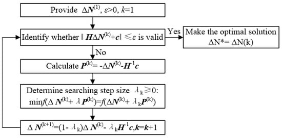
Figure 2.
Iteration process of damped Newton method.
2.5. Optimization Process for the Reasonable Construction State of Cable-Stayed Bridge with Steel Girder
Based on the above analysis, the optimization process for the construction state of a cable-stayed bridge with a steel box girder using the multi-objective programming method can be summarized as follows:
- (1)
- Establish the finite element model of the cable-stayed bridge with the steel box girder based on the forward-iteration method. Calculate the influence matrices for displacement and bending moment of the girder and pylon, and cable force under unit cable force according to the actual construction process.
- (2)
- Use the cable force under the reasonable completed state as initial iterative cable tension to conduct forward-iteration calculation and make k = 1; then, calculate vectors of bending moment , displacement of girder and pylon, and cable force under current completed state. The difference vector for each control parameters between the reasonable completed state and the current completed state can be determined.
- (3)
- Based on Equation (4), a multi-objective programming model can be established by taking as the optimization objective.
- (4)
- Convert the multi-objective programming model into an unconstrained single-objective programming model using the weighted sum of squares method.
- (5)
- Provide a permissible error . Using MATLAB and the damped Newton method, the adjustment amount for cable tension can be determined.
- (6)
- Use as the updated cable tension and perform the forward-iteration calculation. A new set of control parameters under the current state, along with the updated differences between the current state and the reasonable completed state can then be obtained.
- (7)
- Provide a permissible error and . Verify whether both formulas and are valid. If they are, terminate the iteration. The optimal cable tension during the construction process can be determined. At this stage, the reasonableness of the construction state should be evaluated based on the forward-iteration results. If the calculation results are deemed reasonable, the corresponding reasonable constructing state and reasonable completed state are obtained. If the results are not reasonable, adjust the objective functions or weight coefficients and return to step (3) to rebuild the optimization model and continue the iteration process. This procedure continues until the error meets the specified precision requirements. The implementation process is illustrated in Figure 3.
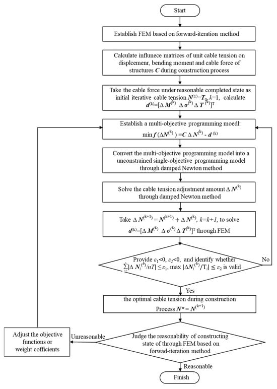
Figure 3.
Optimization process of constructing state for cable-stayed bridge with steel box girder.
3. Optimization on Reasonable Constructing State for Cable-Stayed Bridge with Steel Box Girder
3.1. Engineering Profile
The main bridge of Xiangshan Port Bridge is a five-span continuous, semi-floating cable-stayed bridge featuring a steel box girder, double pylons, and double cable planes. The span arrangement is 82 m + 262 m + 688 m + 262 m + 82 m, as illustrated in Figure 4a. A schematic diagram of the standard cross-sectional dimensions of the main beam is given in Figure 4b. The pylons, which have a height of 226.5 m, are designed as diamond-shaped concrete structures with a concrete grade of C50. The streamlined steel box girder has a width of 26.4 m and a centerline height of 3.5 m, constructed from Q345D steel. The girder is divided into 11 types, comprising a total of 99 sections. The standard girder sections are erected using the cantilever method with a deck derrick crane, while girder sections near the pylons, transition piers, auxiliary piers, and the closure segments of the side spans are installed using a large floating crane. The stay cables are made of parallel steel wires, with a tensile strength of 1670 MPa. In total, there are 176 cables arranged in a spatial fan-shaped configuration.
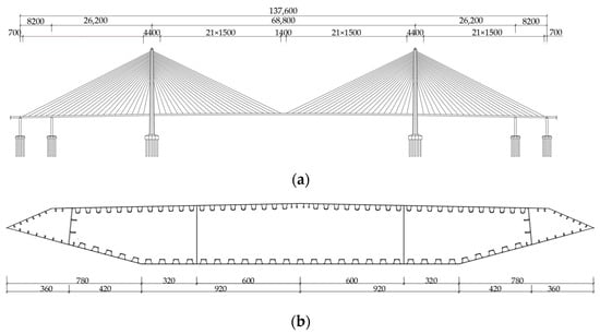
Figure 4.
Layout of Xiangshan Port bridge (a). Dimension drawing of bridge span arrangement (b). Standard cross-section dimension drawings (unit: cm).
3.2. Finite Element Model and Construction Stages
A finite element model of Xiangshan Port Bridge was developed using the finite element software program MIDAS Civil 2015. The “herringbone” mode was adopted for the analysis. The main girder, pylons, and pylon crossbeams are modeled using beam elements, while the stay cables are represented by spatial truss elements. The connections between the cables, main girder, pylons, and crossbeams are simulated using rigid arms. The bottom of the pylons is fixed, and vertical and horizontal restraints are applied to the main girder at the corresponding locations of the transition piers and auxiliary piers. The bridge consists of a total of 967 nodes and 758 elements. The material properties used in the finite element model are listed in Table 1. Figure 5 presents the finite element model of the entire bridge in space. The elasticity modulus of the stay cables was corrected using the Ernst formula to account for the sag effect of the stay cables.

Table 1.
Material properties for all.
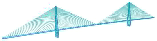
Figure 5.
Schematic diagram of finite element model.
During the construction process, the girder and pylon are temporarily consolidated. The construction sequence is divided into 88 stages, as outlined in Table 2. Due to the geometric and construction symmetry of the bridge structure, Figure 6 provides a schematic diagram of the numbering of the box girder and stay cables, taking half of the bridge span as an example. The main span stay cables are numbered from J1 to J22, spanning from the bridge tower to the mid-span. The side span stay cables are numbered from A1 to A22, running from the bridge tower to the transition pier. The self-weight of the structure during the construction process was calculated based on the actual cross-sectional dimensions. The dead load for the second phase (including the deck pavement, guardrails, and other bridge accessories) was 60.5 kN/m. Temporary construction loads, temporary restraints, and dead loads for the second phase were applied in stages according to the actual construction steps.
Table 2.
Construction stages of Xiangshan Port Bridge.
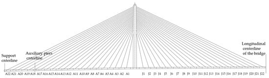
Figure 6.
Schematic division of components.
3.3. Calculation of Influence Matrices During Construction Process
Following the process outlined in Figure 3, the influence matrices for displacement, bending moment, and cable forces of the structure under unit cable tension are calculated during the construction process, as shown in Figure 7, Figure 8, Figure 9, Figure 10 and Figure 11. These calculations allow for the identification of the most sensitive cables corresponding to each state of the main girder and pylons. Given the symmetry of the bridge structure, the influence matrices are computed using a half-bridge model, with a unit cable force of 1000 kN for each cable.
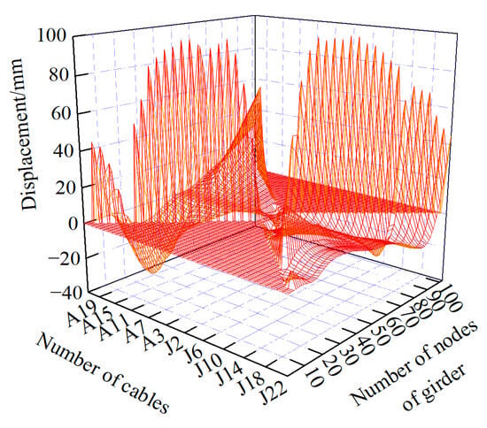
Figure 7.
Influence matrix of construction cable tension on vertical displacement of main girder.
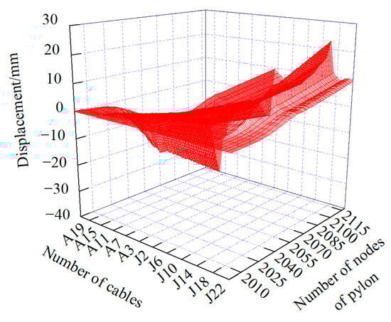
Figure 8.
Influence matrix of construction cable tension on horizontal displacement of pylon.
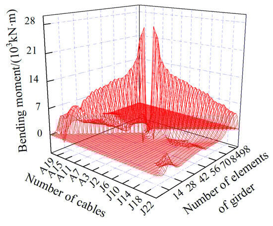
Figure 9.
Influence matrix of construction cable tension on bending moment of main girder.
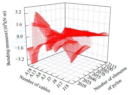
Figure 10.
Influence matrix of construction cable tension on bending moment of pylon.
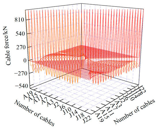
Figure 11.
Influence matrix of construction cable tension on cable force.
As illustrated in Figure 12 and Figure 13, the cable tensions in J9 and A17 had the greatest influence on the vertical displacement of the girder during the construction process. Under a unit cable tension of J9 at the main span side, the maximum upward deflection of the girder reached 98 mm, located at the cantilever end of the mid-span. In contrast, under a unit cable tension of A17 at the side span side, the maximum downward deflection of the girder was 35 mm, occurring at the cantilever end of the side span. Regarding the horizontal displacement of the pylon, the cable tensions in J16 and A17 exhibited the most significant effects. Under a unit cable tension of J16 at the main span side, the horizontal displacement at the top of the pylon was 23 mm, with the displacement directed toward the main span. Conversely, under a unit cable tension of A17 at the side span side, the horizontal displacement at the top of the pylon was 40 mm, inclined toward the side span.
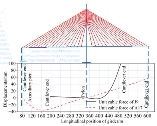
Figure 12.
Vertical displacement of main girder under unit construction cable force.
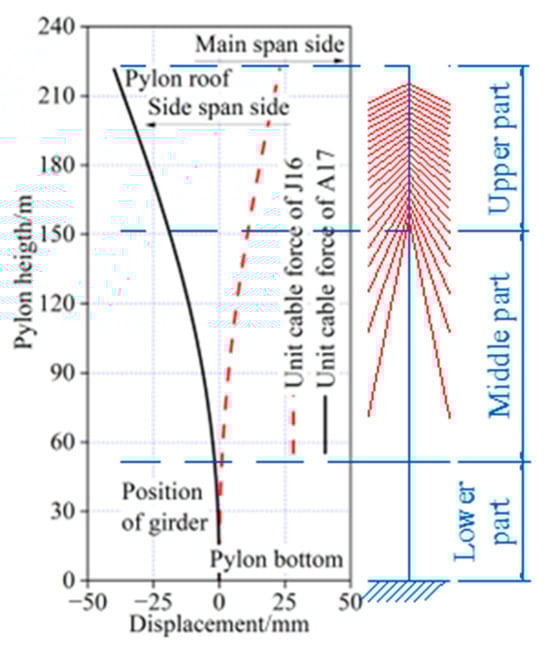
Figure 13.
Horizontal displacement of pylon under unit construction cable force.
As shown in Figure 14 and Figure 15, the cable tensions in J2 and A22 had the most significant impact on the bending moment of the girder during the construction process. Under a unit cable tension of J2 near the pylon, the maximum positive bending moment of the main girder reached 26,876 kN·m, located near the support between the girder and the pylon. Conversely, under a unit cable tension of A22 at the side span, the maximum negative bending moment of the main girder was −3494 kN·m, occurring at the section of the girder above the auxiliary pier. Regarding the bending moment in the pylon, the cable tensions in J16 and A17 showed the largest effects. Under a unit cable tension of J16 at the mid-span side, the maximum positive bending moment of the pylon was 44,388 kN·m, located at the bottom of the pylon. On the other hand, under a unit cable tension of A17 at the side span side, the maximum negative bending moment of the pylon was −71,588 kN·m, also occurring at the bottom of the pylon.
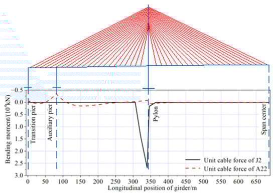
Figure 14.
Bending moment of main girder under unit construction cable force.
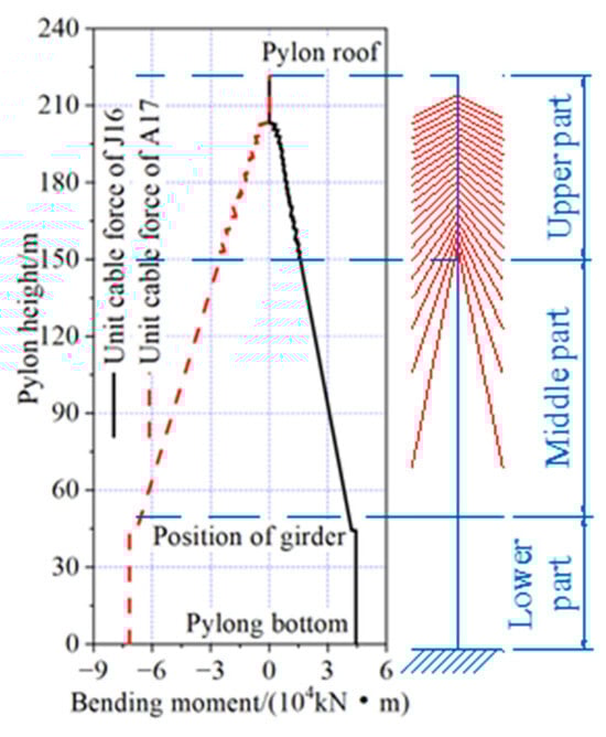
Figure 15.
Bending moment of pylon under unit construction cable force.
3.4. Setting Optimization Parameters
Four types of objective functions were selected for comparison and analysis of the optimization results during the construction process and under dead loads, as shown in Table 3. Through trial runs, the following parameters were determined for the optimization process: the initial iterative values for the construction cable tension ( represents the predetermined cable force under reasonable completed state), and the weight coefficients for cable tension, bending moment, and displacement, denoted as , , and , respectively. The convergence criterion for the damped Newton method was set to , and the convergence criterion for the forward-iteration method was set to and .
Table 3.
Kinds of objective functions.
3.5. Analysis of Optimization Results During Construction Process
The ratio of the 2-norm value to the initial value of the four objective functions was used to represent their relative magnitudes. The changes in these ratios with respect to the number of iterations are shown in Figure 16. After eight iterations, the convergence criterion for the objective functions of Function III was met, with values of , and , indicating that the iteration process had converged. For the other three optimization functions, convergence was achieved after 14, 8, and 9 iterations, respectively.
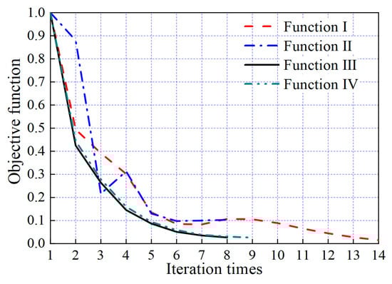
Figure 16.
Change of objective function value along with number of iterations.
The optimized construction cable tensions for the four objective functions are shown in Figure 17. All distributions exhibit a similar trend, with cable tension increasing from the area near the pylon to the transition pier on both sides. The maximum cable tension for each objective function occurred at cable J22 on the mid-span side, while the minimum cable tension was found at cable J5 near the pylon. The optimized cable tensions with Function III the as the objective function ranged from 1481 kN to 3237 kN. The maximum cable tension was 1.70% lower than the result from Function I as the objective function but 0.69% and 3.26% higher than the results from the other two objective functions, respectively. The minimum cable tension was 3.46% lower than that the result with Function I as the objective function, and 0.54% and 27.12% higher than the results from the other two objective functions, respectively.
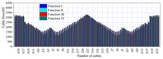
Figure 17.
Optimized construction tension force of stay cables.
The envelopes of vertical displacement of the girder and horizontal displacement of the pylon during the construction process, optimized by the four objective functions, are shown in Figure 18 and Figure 19. The vertical displacement of the girder optimized with Function III as the objective function was in the range of −49 mm to 1198 mm. The maximum upward deflection was 46 mm smaller than the result optimized with Function I as the objective function, and 6 mm and 54 mm larger than the results from the other two objective functions. The maximum downward deflection was the same as the results obtained from the other three objective functions.
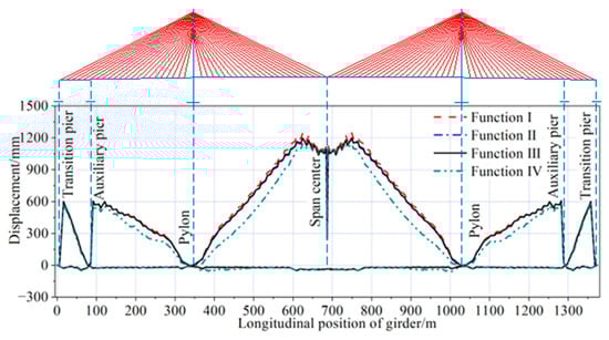
Figure 18.
Vertical displacement envelope of girder during construction.
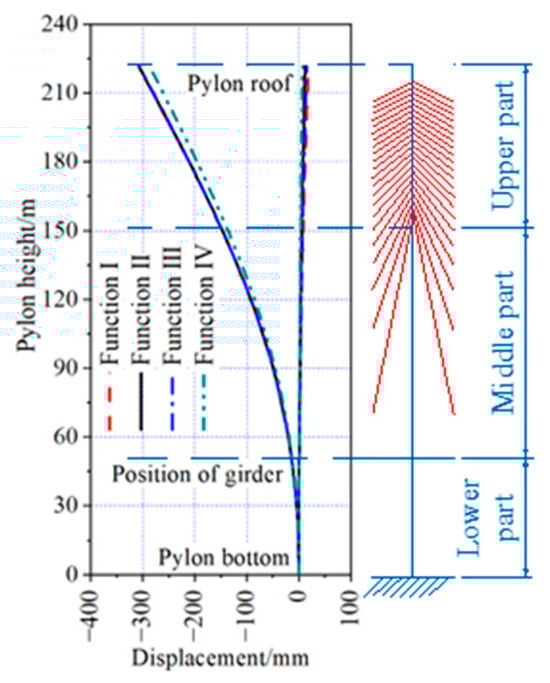
Figure 19.
Horizontal displacement envelope of pylon during construction.
The horizontal displacement of the top of the pylon optimized with Function III as the objective function was in the range of −307 mm to 15 mm. The maximum horizontal displacement inclined to the side span was 21 mm larger than the results optimized with Function IV as the objective function and was the same as the results from the other two objective functions. The maximum horizontal displacement inclined to the main span was 4 mm smaller than the result optimized with Function I as the objective function, and 3 mm and 8 mm larger than the results optimized by the other two objective functions, respectively.
The envelopes of axial force in the girder and pylon during the construction process, optimized by the four objective functions, are shown in Figure 20 and Figure 21. The maximum axial compressive force in the girder was located near the pylon, while the maximum axial compressive force in the pylon was located at the pylon bottom. Using Function III as the objective function for optimization, the axial force of the main girder during the construction phase ranged from −94,061 kN to 191 kN, while the axial force of the bridge towers ranged from −619,899 kN to −1810 kN. The results showed minimal differences compared to the optimization outcomes of the other three objective functions, which can be considered negligible.
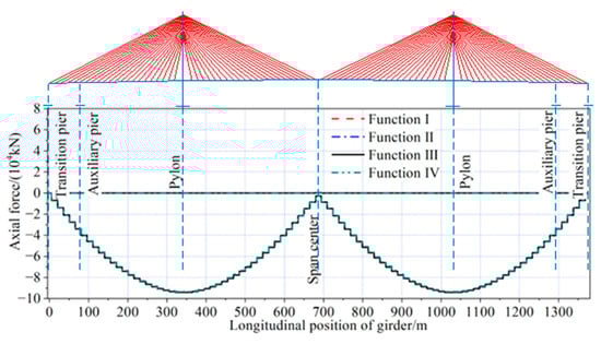
Figure 20.
Axial force envelope of main girder during construction.
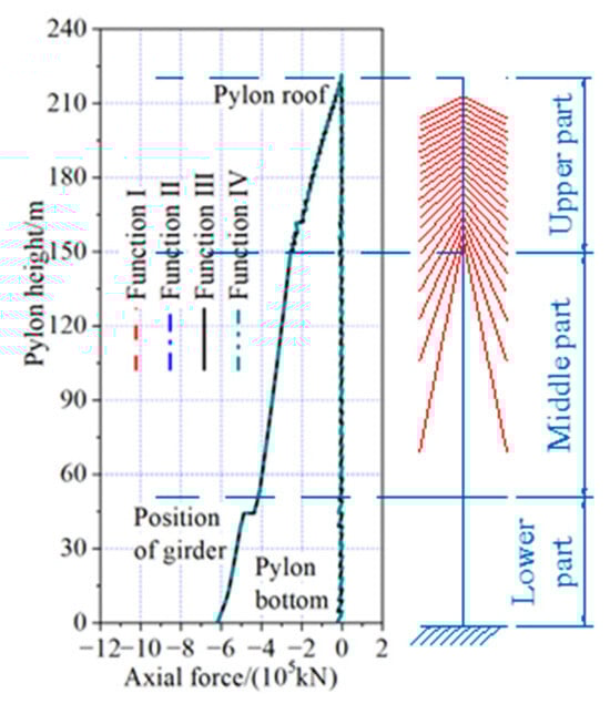
Figure 21.
Axial force envelope of pylon during construction.
The envelopes of the bending moments in the girder and pylon during the construction process, optimized by the four objective functions, are shown in Figure 22 and Figure 23. The maximum positive bending moment in the girder was located near the pylons. The maximum negative bending moment in the girder was located on top of the auxiliary piers. For the pylon, both the maximum positive and negative bending moments in the pylon were located at the pylon bottom.
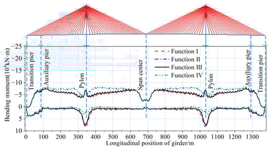
Figure 22.
Bending moment envelope of main girder during construction.
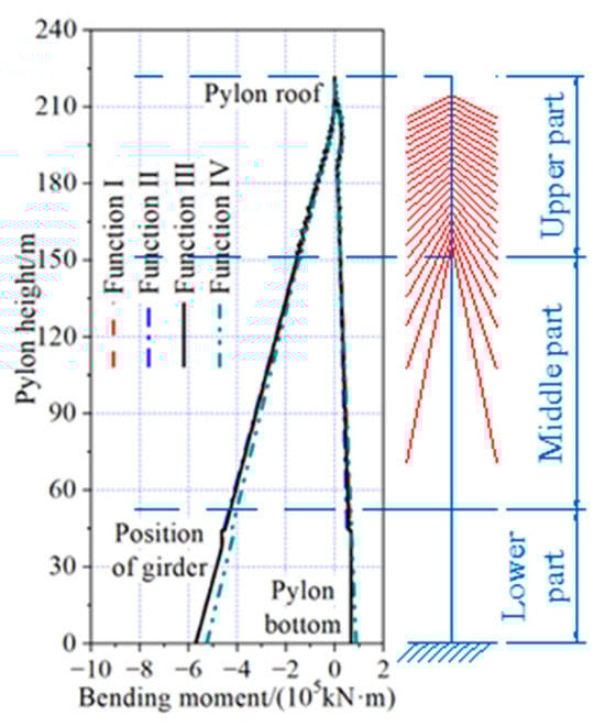
Figure 23.
Bending moment envelope of pylon during construction.
Table 4 presents the detailed values of the maximum positive and negative bending moments for the main beam and bridge tower under different objective functions. As shown in Table 4, it is clear that the maximum positive bending moment of the main beam obtained by optimizing with Function III as the objective function was 159.61% greater than the maximum positive bending moment obtained by optimizing with Function IV as the objective function, and 6.26% and 3.92% smaller than the other two objective functions, respectively. The maximum negative bending moment of the main beam was 0.16%, 0.03%, and 5.65% smaller than the results from the other three objective functions.
Table 4.
Maximum and minimum bending moment in the girder and pylon during construction (kN·m).
The maximum positive bending moment in the pylon by optimizing with Function III as the objective function was 0.60% larger than the results optimized with Function II as the objective function, and 0.27% and 23.57% smaller than the results from the other two objective functions, respectively. The maximum negative bending moment was 8.42% larger than the results optimized with Function IV as the objective function, and 0.31% and 0.02% smaller than the results from the other two objective functions.
The maximum and minimum cable forces during the construction process, optimized by the four objective functions, are shown in Figure 24 and Figure 25. The maximum cable force was located at cable A20, and the minimum cable force was located at cable J5. The cable forces during the construction process, optimized with Function III as the objective function, ranged from −1317 kN to 4348 kN. The maximum cable force was the same as the results optimized with Function IV as the objective function and was 0.75% and 0.11% smaller than the results optimized by the other two objective functions, respectively. The minimum cable force was 0.46%, 0.23%, and 13.05% smaller than the results optimized by the other three objective functions.
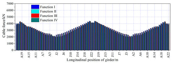
Figure 24.
Maximum cable forces during construction.
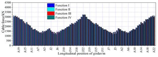
Figure 25.
Minimum cable forces during construction.
The maximum and minimum vertical reactions of the transition piers and auxiliary piers during the construction process, optimized by the four objective functions, are shown in Table 5. The maximum vertical reactions were located at the auxiliary piers, while the minimum vertical reactions were 0 kN. The vertical reactions during the construction process, optimized with Function III as the objective function, ranged from 0 to 9783 kN. The maximum vertical reaction was the same as the results optimized with Function II as the objective function and was 2.74% and 2.47% smaller than the results optimized by the other two objective functions, respectively.
Table 5.
Maximum and minimum vertical reactions of transition piers and auxiliary piers supports during construction (kN).
3.6. Analysis Results Under Dead Loads
The vertical displacement of the main girder and the horizontal displacement of the pylon, optimized by the four objective functions under dead load, are shown in Figure 26 and Figure 27. The maximum upward deflection of the girder, optimized by all four objective functions, was located near the closure segments of the side span. The maximum downward deflection of the girder, optimized with Function I and Function III as the objective functions, was located near the closure segments of the secondary side span. In contrast, the maximum downward deflection optimized by the other two objective functions was located near the pylons. The horizontal displacement of the top of the pylons, optimized by all four objective functions, was inclined toward the side span.
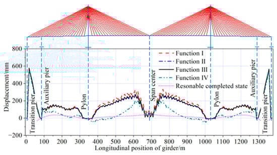
Figure 26.
Vertical displacement of main girder under dead load.
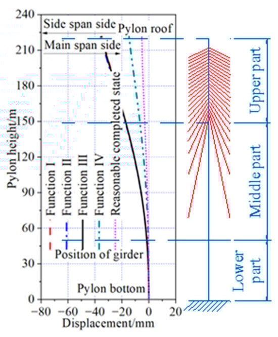
Figure 27.
Horizontal displacement of pylon under dead load.
The vertical displacement of the main girder optimized with Function III as the objective function was in the range of −14 mm to 578 mm. The maximum upward deflection was 5 mm, 5 mm, 22 mm, and 535 mm larger than the results optimized by the other three objective functions and the reasonable completed state, respectively. The maximum downward deflection was 34 mm and 24 mm smaller than the results optimized with Function IV as the objective functions, and the reasonable completed state, respectively, while it was 7 mm and 4 mm larger than the results optimized by the other two objective functions.
The horizontal displacement of the top of the pylons optimized with Function III as the objective function was 35 mm inclined toward the side span. This result was the same as the outcome optimized with Function I as the objective function, 1 mm smaller than the result optimized with Function II as the objective function, and 21 mm and 30 mm larger than the results optimized with Function IV as the objective function, as well as the reasonable completed state.
The axial force of the girder and pylon, optimized by the four objective functions under dead load, are shown in Figure 28 and Figure 29. All four optimization results exhibit a similar distribution, with the axial force in the girder increasing uniformly from the transition piers on both sides toward the pylon, and the axial force in the pylon increasing evenly from the top to the bottom. Both the axial forces in the girder and pylon were predominantly compressive.
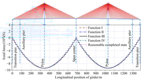
Figure 28.
Axial force of main girder under dead load.
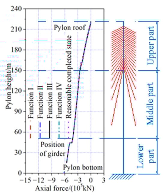
Figure 29.
Axial force of pylon under dead load.
The axial force in the girder optimized with Function III as the objective function was in the range of −93,937 kN to 15 kN. The maximum axial compressive force was 0.05% smaller than the results optimized by Function I as the objective function, and the reasonable completed state, respectively. It was the same as the results optimized with Function II as the objective function, and 0.58% larger than the results optimized with Function IV as the objective function. The axial force in the pylon optimized with Function III as the objective function was in the range of −619,524 kN to −1810 kN. The maximum axial compressive force was the same as the results optimized by the Function IV as the objective function, 1.04% smaller than the results for the reasonable completed state, and 0.01% and 0.03% larger than the results optimized by the other two objective functions.
The bending moment of the girder and pylon, optimized by the four objective functions under dead load, is shown in Figure 30 and Figure 31. The maximum positive bending moments, optimized by all four objective functions, were located near the closure segments of the side span. The maximum negative bending moment optimized with Function IV as the objective function was located near the pylons, while the maximum negative bending moment optimized by the other three objective functions was located on top of the auxiliary piers. There were no positive bending moments in the pylon for the results optimized with Function III as the objective function, and the maximum negative bending moment for these functions was located at the pylon bottom. In contrast, the maximum positive bending moment for the other three objective functions was located at the middle part of the upper pylon, while the maximum negative bending moment for these three objective functions was located at the pylon bottom.
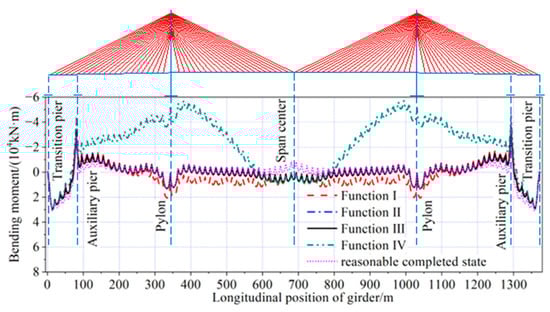
Figure 30.
Bending moment of main girder under dead load.
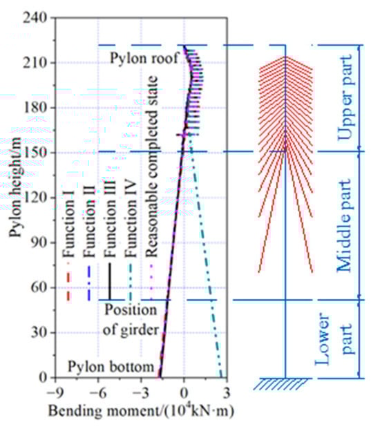
Figure 31.
Bending moment of pylon under dead load.
The bending moment of the girder optimized with Function III as the objective function was in the range of −33,069 kN·m to 29,795 kN·m. The maximum positive bending moment was 0.75%, 0.03%, and 0.09% larger than the results optimized by the other three objective functions, and 3.48% smaller than the results of the reasonable completed state. The maximum negative bending moment was 10.68%, 2.83%, and 41.14% smaller than the results optimized by the other three objective functions, and 15.53% (4446 kN·m) larger than the results of the reasonable completed state.
The bending moment of the pylon optimized with Function III as the objective function was in the range of −16,585 kN·m to 12,463 kN·m. The maximum positive bending moment was 0.33% larger than the results optimized with Function II as the objective function, and 2.85%, 52.22%, and 2.37% smaller than the results optimized by the other two objective functions and the reasonable completed state, respectively. The maximum negative bending moment was 7.19%, 2.40%, and 4.08% larger than the results optimized using Function I, Function II as the objective function, and the reasonable completed state, respectively.
The cable forces optimized by the four objective functions under dead load are shown in Figure 32. The distribution of cable forces was similar for all functions, with the maximum cable force located at cable J22 on the mid-span side and the minimum cable force at cable A1 near the pylons. The cable forces optimized with Function III as the objective function are in the range of 1825 kN to 4098 kN. The maximum cable force was 1.32%, 0.15%, 1.11%, and 1.32% smaller than the results optimized by the other three objective functions and the reasonable completed state, respectively. The minimum cable force was 0.22% smaller than the results optimized by with Function IV as the objective function, and 0.39%, 1.50%, and 0.50% larger than the results optimized by the other two objective functions and the reasonable completed state, respectively. The maximum uneven cable force was 232 kN, which was 53.64% (81 kN), 20.21% (39 kN), 56.76% (84 kN), and 53.64% (81 kN) larger than the results optimized by the other three objective functions and the reasonable completed state, respectively.
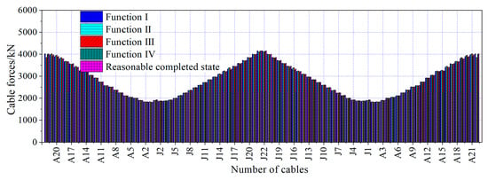
Figure 32.
Cable forces under dead load.
The vertical reactions of transition piers and auxiliary piers optimized by the four kinds of objective functions under dead load, as shown in Table 6, were all positive values, and the vertical reactions of auxiliary piers were larger than those of transition piers. Vertical reactions of transition piers and auxiliary piers optimized with Function III as the objective function were in the range of 4164 kN to 9783 kN, the maximum vertical reaction was 0.20% larger than the results of reasonable completed state, and was 1.49%, 0.01%, and 2.48% smaller than the results optimized by the other three kinds of objective functions, respectively. The minimum support reactions were 1.96%, 0.02%, 2.54%, and 0.26% larger than the optimization results obtained using the other three objective functions and the reasonable completion state, respectively.
Table 6.
Vertical reactions of transitional pier and auxiliary pier supports under dead load (kN).
Based on the analysis above, for a cable-stayed bridge with a steel box girder and a main span of 688 m, constructed using the cantilever method, the optimization of the construction state—through a combination of multi-objective programming and finite element analysis based on the forward-iteration method—results in a reasonable distribution of deformation and internal forces in both the girder and pylon during the construction process. The optimized construction state yields results that show minimal differences when compared to the reasonable completed state.
Due to the cantilever construction method, the bridge exhibits relatively low stiffness during the construction phase. Consequently, a significant portion of the displacement at the cantilever end is not caused by the cable force, but rather by rigid-body displacement. This makes it challenging to achieve the target displacement. Furthermore, optimizing solely based on cable force does not adequately account for the deformation and internal forces in each component. Therefore, it is advisable to select a combination of cable force and bending moment as objective functions in the optimization process. This approach better considers the internal forces in each component during cantilever construction, reduces structural displacement, and is more likely to achieve a reasonable construction state.
4. Conclusions
The optimization problem associated with the construction of steel box girder cable-stayed bridges is addressed in this paper, which introduces a novel optimization method to determine the appropriate construction cable forces. The following useful conclusions can be drawn:
- (1)
- Based on the structural characteristics of a steel box girder cable-stayed bridge, the problem of determining a reasonable construction state was formulated as a multi-objective programming model. The weighted sum of squares method was employed in the evaluation function, followed by the damped Newton method to solve the unconstrained single-objective model, and finite element analysis based on the forward-iteration method was applied sequentially to solve the problem.
- (2)
- For a steel box girder cable-stayed bridge constructed using the cantilever method, the optimization of the construction state, incorporating objective functions related to cable force and bending moment and combining multi-objective programming with finite element analysis based on the forward-iteration method, yields deformation and internal force distributions of both the girder and pylon that are within reasonable ranges during the construction process. These results exhibit minimal deviation from the completed state obtained from the optimized construction state. The selected objective functions and optimization algorithm effectively account for the deformation and internal forces of each component during cantilever construction, leading to a more reasonable construction state.
- (3)
- In selecting the appropriate objective functions for optimizing the reasonable construction state of a steel box girder cable-stayed bridge, the structural characteristics and construction methods must be considered. Simply selecting cable force as the sole objective function may overlook the deformation and internal forces of individual components. Additionally, excessive or ill-suited objective functions can hinder the convergence of the iteration process.
- (4)
- The multi-objective optimization algorithm demonstrated excellent stability and fast convergence, making it straightforward to obtain the global optimal solution. It is also easily programmable, enabling the structure’s deformation and internal forces to closely approximate the target of a reasonable completed state while ensuring construction safety. This method not only avoids the randomness associated with manual adjustments but also provides a quick and efficient means to achieve reasonable results. The optimization outcomes offer a theoretical foundation for construction control and error adjustment in the construction of steel box girder cable-stayed bridges.
- (5)
- For large-span cable-stayed bridges, the high-order matrices in the mathematical optimization models for final bridge cable forces can encounter singularity issues during computation, leading to local convergence problems. This limitation highlights the need for further optimization of the algorithms to enhance both efficiency and global convergence. Additionally, emerging intelligent optimization algorithms offer significant advantages and could be promising candidates for application in optimizing the final cable forces of cable-stayed bridges. Exploring these algorithms may lead to the development of more suitable methods or ensembles of algorithms specifically tailored for the optimization of cable forces in such structures.
Author Contributions
Conceptualization, J.H., W.C. and W.H.; methodology, J.H., W.H. and J.D. (Jie Dai); software, W.C.; validation, J.D. (Jie Dai), J.D. (Jin Di) and F.Q.; formal analysis, J.H., W.C. and J.D. (Jie Dai); investigation, J.H., W.C. and W.H.; resources, J.D. (Jie Dai), J.D. (Jin Di) and F.Q.; data curation, J.H., W.C. and W.H.; writing—original draft preparation, J.H. and W.C.; writing—review and editing, J.D. (Jin Di) and F.Q.; visualization, J.H. and W.H.; supervision, J.H., W.C. and W.H.; project administration, J.H. and W.H.; funding acquisition, J.D. (Jin Di) and F.Q. All authors have read and agreed to the published version of the manuscript.
Funding
This research was funded by the National Natural Science Foundation of China (grant number: 52192663) and the National Key R&D Program of China (grant number: 2021YFF0501004).
Institutional Review Board Statement
Not applicable.
Informed Consent Statement
Not applicable.
Data Availability Statement
The original contributions presented in this study are included in the article. Further inquiries can be directed to the corresponding author.
Conflicts of Interest
Authors Junbiao He and Weiming Hu were employed by the company China Harbour Engineering Company Limited. The remaining authors declare that the research was conducted in the absence of any commercial or financial relationships that could be construed as a potential conflict of interest.
References
- Hassan, M.M.; EI Damatty, A.A.; Nassef, A.O. Database for the optimum design of semi-fan composite cable-stayed bridges based on genetic algorithms. Struct. Infrastruct. Eng. 2015, 11, 1054–1068. [Google Scholar] [CrossRef]
- Schlaich, M. Erection of cable-stayed bridges having composite decks with precast concrete slabs. J. Bridge Eng. 2001, 6, 333–339. [Google Scholar] [CrossRef]
- Zeng, Y.; Wang, Y.; Shi, Z.; Tan, H.; Gu, A. Experimental study on stability of long-span PC cable-stayed bridge during the construction periods. Adv. Civ. Eng. 2022, 2022, 8578684. [Google Scholar] [CrossRef]
- Sung-Wan, K.; Dong-Uk, P.; Jin-Soo, K.; Park, J.-B. Estimating tension of a prestressed concrete cable-stayed bridge under construction and traffic use conditions using a vision-based system. Structures 2023, 47, 299–312. [Google Scholar] [CrossRef]
- Janjic, D.; Pircher, M.; Pircher, H. Optimization of cable tensioning in cable-stayed bridges. J. Bridge Eng. 2003, 8, 131–137. [Google Scholar] [CrossRef]
- Song, C.; Xiao, R.; Sun, B.; Wang, Z.; Zhang, C. Cable force optimization of cable-stayed bridges: A surrogate model-assisted differential evolution method combined with B-Spline interpolation curves. Eng. Struct. 2023, 283, 115856. [Google Scholar] [CrossRef]
- Freire, A.M.S.; Negrao, J.H.O.; Lopes, A.V. Geometrical nonlinearities on the static analysis of highly flexible steel cable-stayed bridges. Comput. Struct. 2006, 84, 2128–2140. [Google Scholar] [CrossRef]
- Wang, L.; Xiao, Z.; Li, M.; Li, M.; Fu, N. Cable force optimization of cable-stayed bridge based on multi-objective particle swarm optimization algorithm with mutation operation and the influence matrix. Appl. Sci. 2023, 13, 2611. [Google Scholar] [CrossRef]
- Dai, J.; Qin, F.; Di, J.; Chen, Y. Review on cable force optimization method for cable-stayed bridge in completed bridge state. China J. Highw. Transp. 2019, 32, 17–37. (In China) [Google Scholar] [CrossRef]
- Wei, S.; Gong, W.; Wu, X.; Zhang, Z. Nonlinear stress-free-state forward analysis method of long-span cable-stayed bridges constructed in stages. Buildings 2023, 13, 1735. [Google Scholar] [CrossRef]
- Lozano-Galant, J.A.; Payá-Zaforteza, I.; Xu, D.; Turmo, J. Forward algorithm for the construction control of cable-stayed bridges built on temporary supports. Eng. Struct. 2012, 40, 119–130. [Google Scholar] [CrossRef]
- Granata, M.F.; Longo, G.; Recupero, A.; Arici, M. Construction sequence analysis of long-span cable-stayed bridges. Eng. Struct. 2018, 174, 267–281. [Google Scholar] [CrossRef]
- Chen, D.W.; Au, F.T.K.; Tham, L.G.; Lee, P.K.K. Determination of initial cable forces in prestressed concrete cable-stayed bridges for given design deck profiles using the force equilibrium method. Comput. Struct. 2000, 74, 1–9. [Google Scholar] [CrossRef]
- Fabbrocino, F.; Modano, M.; Farina, I.; Carpentieri, G.; Fraternali, F. Optimal prestress design of composite cable-stayed bridges. Compos. Struct. 2017, 169, 167–172. [Google Scholar] [CrossRef]
- Martins, A.M.B.; Simões, L.M.C.; Negrão, J.H.J.O. Cable stretching force optimization of concrete cable-stayed bridges including construction stages and time-dependent effects. Struct. Multidiscip. Optim. 2015, 51, 757–772. [Google Scholar] [CrossRef]
- Chen, Z.; Zhang, C.; Zhou, J.; Song, J.; Huang, C. Study of cable force of construction control and alignment control of main girders for long-span railway cable-stayed bridges. Mod. Appl. Sci. 2013, 7, 47. [Google Scholar] [CrossRef]
- Sung, Y.; Chang, D.; Teo, E. Optimum post-tensioning cable forces of Mau-Lo His cable-stayed bridge. Eng. Struct. 2006, 28, 1407–1417. [Google Scholar] [CrossRef]
- Baldomir, A.; Hernandez, S.; Nieto, F.; Jurado, J.A. Cable optimization of a long span cable stayed bridge in La Coruña (Spain). Adv. Eng. Softw. 2010, 41, 931–938. [Google Scholar] [CrossRef]
- Lonetti, P.; Pascuzzo, A. Optimum design analysis of hybrid cable-stayed suspension bridges. Adv. Eng. Softw. 2014, 73, 53–66. [Google Scholar] [CrossRef]
- Guo, J.; Guan, Z. Optimization of the cable forces of completed cable-stayed bridges with differential evolution method. Structures 2023, 47, 1416–1427. [Google Scholar] [CrossRef]
- Tian, Z.; Zhang, Z.; Ning, C.; Peng, T.; Guo, Y.; Cao, Z. Multi-objective optimization of cable force of arch bridge constructed by cable-stayed cantilever cast-in-situ method based on improved NSGA-II. Structures 2024, 59, 105782. [Google Scholar] [CrossRef]
- Guo, J.; Yuan, W.; Dang, X.; Alam, M.S. Cable force optimization of a curved cable-stayed bridge with combined simulated annealing method and cubic B-Spline interpolation curves. Eng. Struct. 2019, 201, 109813. [Google Scholar] [CrossRef]
- Li, J.X.; Qu, C.X.; Yi, T.H.; Li, H.-N.; Han, Q. Condition assessment of stay cables using normalized sequence of vehicle-induced cable force peaks of stay cables on same side. Eng. Struct. 2024, 309, 118123. [Google Scholar] [CrossRef]
- Matos, J.C.; Nicoletti, V.; Kralovanec, J.; Sousa, H.S.; Gara, F.; Moravcik, M.; Morais, M.J. Comparison of condition rating systems for bridges in three European countries. Appl. Sci. 2023, 13, 12343. [Google Scholar] [CrossRef]
- Madrazo-Aguirre, F.; Ruiz-Teran, A.M.; Wadee, M.A. Dynamic behaviour of steel–concrete composite under-deck cable-stayed bridges under the action of moving loads. Eng. Struct. 2015, 103, 260–274. [Google Scholar] [CrossRef]
- Madrazo-Aguirre, F.; Wadee, M.A.; Ruiz-Teran, A.M. Non-linear stability of under-deck cable-stayed bridge decks. Int. J. Non-Linear Mech. 2015, 77, 28–40. [Google Scholar] [CrossRef][Green Version]
- Wu, K.; Wadee, M.A.; Gardner, L. Stability and ultimate behaviour of prestressed stayed beam-columns. Eng. Struct. 2019, 201, 109723. [Google Scholar] [CrossRef]
Disclaimer/Publisher’s Note: The statements, opinions and data contained in all publications are solely those of the individual author(s) and contributor(s) and not of MDPI and/or the editor(s). MDPI and/or the editor(s) disclaim responsibility for any injury to people or property resulting from any ideas, methods, instructions or products referred to in the content. |
© 2024 by the authors. Licensee MDPI, Basel, Switzerland. This article is an open access article distributed under the terms and conditions of the Creative Commons Attribution (CC BY) license (https://creativecommons.org/licenses/by/4.0/).