Abstract
To ensure security and stable quality, deeper cybersecurity evaluations are essential for the development of safety features and functionalities in vehicles. Among these, the AEB system is the most relevant. This research presents a comprehensive TARA of the AEB system, emphasizing the identification, validation, and mitigation of major cybersecurity threats and risks. We systematically examine potential attack vectors by utilizing the STRIDE threat model. This approach enables a detailed analysis of each security threat associated with AEB systems, providing insights into how malicious actors could use the attack paths. The assessment aligns with ISO/SAE 21434, which offers a robust framework for risk management in automotive cybersecurity and IT security, ensuring a thorough evaluation of a system’s architecture. By assessing the AEB system’s architecture against these standards, we identify key components and communication pathways that may be particularly prone to cyberattacks. The results of this analysis highlight critical flaws within the AEB framework and propose corrective measures to enhance cybersecurity resilience. This article provides a structured methodology for assessing and mitigating automotive cybersecurity risks in compliance with industry standards, aiming to facilitate the safe implementation of AEB technology and ultimately improve overall vehicle security and safety.
1. Introduction
Road accidents continue to be a major cause of fatalities and serious injuries globally, driven by increasing traffic density and distractions while driving. To combat this critical issue, it is vital to develop and implement technological solutions that significantly enhance vehicle safety. Among the most promising advancements in this domain is the autonomous emergency braking AEB system, which is designed to automatically prevent or mitigate collisions, thereby reducing the risk of accidents and saving lives.
To ensure reliability and security in AEB systems, thorough validation is required to ensure that every single component operates correctly under diverse conditions. These systems rely on the complex interaction of advanced sensors, data fusion algorithms, decision-making processes, and actuator controls. Given the stringent reliability standards and the growing architectural complexity of AEB systems, sophisticated testing methodologies—such as functional testing, HIL simulations, and scenario-based evaluations—are essential. These methodologies are crucial for identifying and addressing potential vulnerabilities before vehicles are brought to the market, thereby ensuring the reliability of AEB systems. Moreover, tire slip control is another critical topic in vehicle dynamic control, being the basis of systems, including the AEB system, as shown by Meléndez-Useros et al. [1]. Another typical application in research regards platooning techniques, as demonstrated by Viadero-Monasterio et al. [2], which underline the need for a more secure and standard-compliant solution, particularly in the context of AEB, which is crucial when taking into account the challenges coming from smart intersections, as discussed by Gao et al. [3].
As AEB systems increasingly integrate with other automotive technologies, they face heightened exposure to cyber threats, making cybersecurity a paramount concern. It is imperative to implement robust cybersecurity measures to protect data integrity, ensure secure communications, and enable real-time threat detection. An integrated approach that combines comprehensive testing protocols with advanced cybersecurity measures is essential for ensuring the safety and resilience of AEB systems in contemporary vehicles.
To standardize quality and security assessments for manufactured vehicles, the International Organization for Standardization ISO and the Society of Automotive Engineers Society of Automotive Engineers SAE have proposed several standards. Notably, ISO/SAE 21434 [4] provides a comprehensive framework for cybersecurity and quality checks aimed at original equipment manufacturers (OEMs) and suppliers. Additionally, ISO 24089 [5] enhances this framework by emphasizing information-sharing and impact analysis, thereby strengthening the overall security posture. The importance of AEB systems is further highlighted by their alignment with these standards, which collectively facilitate a thorough evaluation of systems’ architecture and hardware security.
This paper analyzes the critical components of typical AEB systems in accordance with the ISO/SAE 21434 standard. To deepen the understanding of their functionality and security, an architecture is developed to identify threats, as outlined by ISO 21434, and the STRIDE methodology is applied to assess these vulnerabilities.
The primary contributions of the present paper are outlined as follows:
- Analysis of AEB Architecture Components: this work provides an extensive examination of the essential components that constitute a typical AEB architecture.
- Security Evaluation of AEB Architectures Utilizing ISO/SAE 21434: The ISO/SAE 21434 standard, a recognized cybersecurity framework specifically tailored for automotive systems, is implemented to perform a thorough security evaluation of AEB architectures. By applying this structured methodology, the rigor of the security assessment is enhanced, providing actionable insights for improving AEB system resilience.
- In-Depth Analysis and Countermeasures for High-Risk AEB Threats: This investigation delves into the root causes and potential impacts of high-risk threats targeting AEB systems. Through detailed analysis, critical vulnerabilities are identified, and effective countermeasures are developed to address these threats. This proactive examination not only strengthens the security posture of AEB systems but also contributes to the broader discourse on safeguarding automotive safety technologies against emerging cyber threats.
To establish a clear and coherent manuscript, this document is structured into nine distinct sections:
- Section 2 reviews related work pertinent to AEB and threat analysis within the automotive domain.
- Section 3 outlines the research methodology employed, emphasizing the objectives of this study and the research questions addressed.
- Section 4 details the main features encountered in the literature, focusing on threat modeling based on the selected architecture. It includes an in-depth description of each AEB system component, a data flow diagram, and a system design diagram illustrating the AEB architecture.
- Section 5 presents an overview of the TARA methodology used for the security evaluation of the chosen architecture.
- Section 6 presents the findings of the risk analysis, providing an overview of all risk levels along with associated threats. Following this, an in-depth examination of the critical and high-risk levels is conducted, focusing on potential attacks on the architecture and corresponding mitigation strategies. Additionally, this section includes a comprehensive cybersecurity analysis of potential attacks targeting each component within the system.
- Section 7 discusses improvements to the architecture, proposing enhanced security measures for the involved components, and provides a comprehensive perspective on the context and considerations for implementing cybersecurity measures.
- Section 8 concludes with a summary of the research findings.
2. Related Work
Recent studies have focused on enhancing the safety and reliability of ADAS in vehicles. Notably, research has been conducted on the AEB system, a crucial safety feature designed to prevent or mitigate collisions. However, many of these studies lack alignment with ISO standards, limiting their applicability within standardized frameworks. In Ye et al. [6] and Kim et al. [7], the authors explore various aspects of AEB systems, including collision threat assessment models, actuator control mechanisms, and testing methodologies.
One study presents an improved TTC model that incorporates relative acceleration, enhancing accuracy in predicting potential collisions, as discussed by Ye et al. [6]. While this ETTC model addresses certain limitations in traditional TTC approaches—particularly in scenarios where the target vehicle is decelerating—it does not fully adhere to standardized testing and validation protocols as outlined by ISO standards.
Additionally, Tang et al. [8] investigate the integration of V2V communication with pedestrian autonomous emergency braking (PAEB) systems to overcome the limitations of onboard sensors and enhance pedestrian safety. Although the V2V-PAEB system enables vehicles to share information about detected pedestrians for a more comprehensive view of the surrounding environment, the study lacks the standardized protocols needed for sensor fusion and interoperability according to ISO guidelines.
Finally, another study by Ye et al. [6] proposes a real-time automatic test platform for AEB systems with a brake system in the loop. The study underscores the importance of rigorous testing for AEB systems, given the complexity of real-world traffic conditions. Nevertheless, the proposed platform does not fully incorporate the ISO-recommended HARA procedures, leaving room for further investigation into the alignment of such platforms with standardized safety requirements.
Despite novelties introduced by the discussed work, which provides valuable insights into the development, evaluation, and testing of safety-critical systems like AEB in vehicles, it is essential to note that these sources do not explicitly address cybersecurity aspects related to ADAS or the ISO 21434 standard. Therefore, further research and analysis are necessary to explore the cybersecurity implications of these systems and how they align with the requirements outlined in ISO 21434. The authors of this paper primarily chose these references to conduct a study on the AEB architecture, as shown by Kim et al. [7] and the application of the TARA methodology for cybersecurity.
2.1. Background
2.1.1. AEB Systems
AEB is an advanced driver-assistance system (ADAS) designed to enhance vehicle safety by automatically applying brakes in order to prevent or mitigate collisions. AEB systems employ a variety of sensors, including radar, cameras, and LIDAR, to monitor the vehicle’s surroundings and detect potential collision threats. Upon the detection of a potential collision, the system calculates the requisite braking force and automatically engages the brakes in the event that the driver does not respond in a timely manner. The architecture of AEB systems comprises several critical components, including sensor input, data fusion, decision-making algorithms, and actuator control. It is essential that these components function in a seamless manner to guarantee the system’s effectiveness and reliability.
2.1.2. Security Standard
A comprehensive review of various studies on similar systems highlights a significant lack of discussions or evaluations of AEB security according to established standards. While the literature presents a wide array of approaches, the role of standardization is critical in system analysis. ISO 24089 is a recent standard in the automotive sector, providing guidelines for software update management systems to ensure that vehicle software is securely updated throughout its lifecycle. Despite its relevance in maintaining software integrity, ISO 24089 primarily focuses on the processes for software updates and does not fully address all cybersecurity aspects, as discussed by Agirre et al. [9].
On the other hand, ISO/SAE 21434 is the foundation of the automotive sector’s solution, which offers a thorough framework for handling cybersecurity threats in every stage of a vehicle’s lifecycle, from conception to decommissioning. It incorporates automotive-specific procedures, such as TARA, to detect, evaluate, and reduce risks. It is consistent with the risk management concepts included in ISO 27001 [10], as discussed by Lu et al. [11], which are specifically aimed at automotive cybersecurity, offering a framework to evaluate and mitigate potential security risks. This allows for the development of safer, more secure mobility solutions, as shown by Ariyanto et al. [12]. In the context of AEB systems, the integration of ISO/SAE 21434 standards is essential for comprehensive security assessment. While ISO 24089 ensures secure software update management, ISO/SAE 21434 addresses broader cybersecurity concerns, together providing a holistic view of both the safety and security of AEB systems. As outlined in Table 1, these standards, although complementary, still leave some gaps in accounting for external environmental factors.

Table 1.
Comparison between ISO 24089 and ISO/SAE 21434 standards.
The primary references selected for this study, particularly [7], as shown in Table 1, were chosen to conduct a comprehensive examination of AEB architecture and the application of the TARA methodology for cybersecurity.
3. Research Methodology
This chapter presents the methodological framework utilized for the study of an AEB system. A precise strategy was developed to enhance performance and safety, ensuring a systematic and thorough analysis of potential threats and vulnerabilities. This structured approach facilitated an extensive investigation into the components and effectiveness of AEB systems, providing a robust foundation for selecting an optimal architecture.
The research methodology comprises several distinct phases aimed at systematically analyzing AEB systems in terms of architecture, security, and threat assessment. The workflow, illustrated in Figure 1, delineates the steps followed in this study.
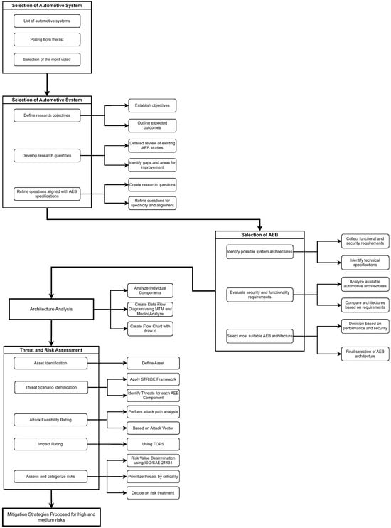
Figure 1.
Workflow of research methodology.
3.1. Selection of Automotive System
The initial step in this methodological approach involved selecting an automotive system for analysis, balancing technological innovation and industry relevance. Industry experts first compiled a comprehensive list of system features, including advanced driver-assistance systems (ADASs), infotainment systems, driver monitoring systems, predictive maintenance alerts, and autonomous emergency braking.
A field expert then refined this list by selecting the ten most significant features, evaluating them based on their importance and potential impact on the automotive industry. These features were subsequently evaluated through a survey involving 35 researchers, who voted on the technologies they deemed most promising.
After analyzing the survey results, the top three technologies emerged: predictive maintenance alerts, autonomous emergency braking AEB, and driver monitoring systems. Participants were divided into groups, each focused on one of the selected technologies, to proceed with a detailed analysis of threats and vulnerabilities. A group of twelve participants specifically focused on AEB.
This division of labor allowed each group to concentrate on one of the most relevant features, enabling an in-depth analysis aimed at developing effective risk mitigation strategies.
3.2. Research Questions
Formulating the research questions was a crucial step in guiding the analysis and focusing on the autonomous emergency braking AEB system. This process was designed to clearly and precisely define the research objectives and develop specific questions addressing the study goals.
The initial step involved establishing research objectives, focusing on the analysis of AEB systems within the existing literature. The primary objective was to identify the various architectures utilized in AEB systems and to determine the most comprehensive architecture, incorporating all relevant functionalities for safety and effectiveness.
Based on these objectives, research questions were formulated to investigate specific aspects related to the security of AEB systems and to evaluate potential threats. These questions were designed to thoroughly assess the robustness of AEB systems against various threats.
As our objective was to analyze the core components of typical autonomous emergency braking AEB systems and evaluate the security of their architectures, we formulated two key questions to address these goals.
- RQ1: Which are the typical components and the connection between these in AEB systems that can be considered possible attack assets?
- RQ2: What are the threats and the associated risks of a typical AEB system?
3.3. Exclusion and Inclusion Criteria
Multiple criteria for selecting the research papers were established to ensure a currently relevant literature review aligned with the objectives of this study. The inclusion criteria targeted papers that specifically addressed AEB systems and cybersecurity frameworks such as STRIDE, particularly in the context of automotive safety and ISO standards like ISO 26262 [13] and ISO/SAE 21434.
Additionally, papers published in peer-reviewed journals or conferences with a clear focus on risk evaluation techniques were prioritized. The exclusion criteria filtered out papers that lacked a direct focus on AEB systems. Those that were not considered scientific approaches and not published in a certified journal or conference, non-English language publications, and papers primarily focused on unrelated automotive systems were also excluded to maintain the relevance of the research. As there are some search engines and web databases focused on scientific research, we used those to extract our papers. Included were Google Scholar, IEEE, SpringerLink, ACM, and Science.gov.
3.4. Study Selection and Data Extraction
AEB systems comprise multiple components that incorporate various technologies for detection, connection, and data processing. A rigorous study selection phase was essential to focus exclusively on the most pertinent and comprehensive works that met our criteria. This research was carried out using electronic databases such as Scopus and Google Scholar, considering documents from 2020 to 2024. Initially, 25 papers were chosen for full-text review. Out of these, only 11 papers were deemed appropriate for the data extraction process. During the data extraction phase, we concentrated on the proposed research questions (RQs) and identified a set of features from each document after a thorough review. These features, relevant to our study, were categorized as follows:
Detection layer—radar, LiDAR, camera, and ultrasonic sensors. Communication layer—vehicle-to-vehicle (V2V), vehicle-to-infrastructure (V2I), and vehicle-to-everything (V2X) GPS. Processing layer—onboard computer, machine learning algorithms, and electronic control units (ECUs).
These features were crucial for addressing the proposed RQs and for identifying the optimal AEB architecture.
3.5. Synthesis
Firstly, Table 2 presents a comprehensive overview of the features critical to the context of autonomous emergency braking AEB systems within the realm of cybersecurity. To achieve the project objectives, the primary reference selected was [7], which served as the foundation for developing the architectural prototype and extracting features essential for conducting the threat analysis and risk assessment (TARA) process.
Specifically, Ref. [14] was highlighted for its focus on mitigating collision risks in hazardous driving situations. The paper details how the system utilizes a controller to engage an electro-hydraulic braking system upon detecting sudden braking by a preceding vehicle, with this information communicated via a Wi-Fi network.
Reference [8] introduces a simulated system that integrates vehicle-to-vehicle (V2V) communication with pedestrian autonomous emergency braking (PAEB) to enhance pedestrian safety. The V2V-PAEB system enables vehicles to exchange information regarding detected pedestrians, thereby improving their ability to avoid collisions.
Additionally, Ref. [15] describes the implementation of an AEB system that employs fuzzy logic to recognize and predict traffic light statuses, facilitating autonomous decision-making and the application of various control algorithms. Other studies primarily focus on system simulations and operational mechanisms.
Table 2.
Occurrence of various components and key attributes in existing research papers.
Table 2.
Occurrence of various components and key attributes in existing research papers.
| Feature/Reference | [11] | [12] | [6] | [7] | [16] | [14] | [8] | [17] | [18] | [15] | [19] |
|---|---|---|---|---|---|---|---|---|---|---|---|
| Security | ✓ | ✓ | ✓ | ✓ | ✓ | ✓ | ✓ | ||||
| Car Application | ✓ | ✓ | ✓ | ✓ | ✓ | ✓ | ✓ | ✓ | ✓ | ✓ | |
| WiFi | ✓ | ||||||||||
| GPS | ✓ | ✓ | ✓ | ||||||||
| Machine Learning | ✓ | ✓ | |||||||||
| Camera | ✓ | ✓ | ✓ | ✓ | ✓ | ✓ | ✓ | ✓ | |||
| V2X | ✓ | ✓ | ✓ | ||||||||
| Sensor Fusion | ✓ | ✓ | ✓ | ✓ | ✓ | ✓ | |||||
| Radar | ✓ | ✓ | ✓ | ✓ | ✓ | ✓ | ✓ | ✓ | ✓ | ✓ | |
| WSS | ✓ | ||||||||||
| ADAS | ✓ | ✓ | ✓ | ✓ | ✓ | ✓ |
3.6. Threat and Risk Assessment
The threat and risk assessment (TARA) phase aimed to identify and analyze the vulnerabilities of the AEB system and evaluate the risks associated with each identified threat. Initially, the selected architecture components and their interconnections were input into the Medini tool, which automatically generated a list of relevant threats.
These threats were subsequently imported into an Excel file, where a detailed analysis was conducted to assess the risk level of each identified threat. This process adhered to a systematic approach, commencing with the identification of critical system assets and concluding with an evaluation of the feasibility and impact of each threat. Threats were categorized using STRIDE.
For each identified threat, potential attack paths and vectors were analyzed, accompanied by a motivational assessment to understand the rationale behind an attacker’s targeting of specific vulnerabilities. The impact was evaluated across multiple dimensions, including driver safety, financial repercussions, operational implications, and issues related to privacy and regulatory compliance.
Threat severity was assessed using a quantitative scale that integrated impacts on FOPS, where we ultimately focussed on the safety risks. Additionally, the feasibility of attacks was evaluated based on the complexity and resources required to execute an effective attack. These parameters facilitated the calculation of the overall risk level for each threat, enabling the ranking of threats by criticality.
Risk treatment decisions encompassed options such as mitigation, acceptance, avoidance, or transfer, based on the severity and feasibility of each identified threat. Mitigation measures were proposed for the high and severe safety threats to enhance security controls, with each decision documented alongside detailed justifications in the accompanying Excel file.
Throughout this process, Medini Analyze and MTM were employed to visualize system component interactions and potential attack paths. Adhering to the guidelines of ISO/SAE 21434 ensured that all risk assessment procedures aligned with established automotive security standards.
This approach provided a thorough understanding of AEB threats and vulnerabilities, forming the basis for implementing mitigation strategies aimed at reducing risk and enhancing system resilience. Specific mitigation strategies were developed for critical risk threats. These strategies focused on reducing the likelihood of successful attacks while minimizing the impact if they occurred.
4. Feature Description
In this section, we describe the major components which characterize the selected architecture, as well as their interaction. We end this section by discussing some considerations on trust and security.
4.1. Threat Modeling Diagram
The diagram depicted in Figure 2 illustrates the high-level architecture of the AEB system. In this context, we meticulously addressed and managed all identified threats associated with the components within the system. The architecture includes a comprehensive overview of the AEB components and their interactions, ensuring a thorough assessment of potential vulnerabilities. Additionally, the tool used in our analysis allowed for the identification and evaluation of potential threats specific to each component in the architecture. By systematically setting and analyzing these threats, we ensured that the AEB system is robust and resilient against various attack vectors. This approach enabled us to proactively address potential security concerns and enhance the overall safety and effectiveness of the AEB system. Basically, the components are interconnected via different communication protocols, primarily using the CAN and secondarily using the ETH.
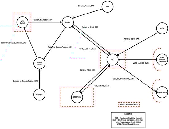
Figure 2.
Threat modeling diagram of architecture proposed in [7].
4.2. Components and Connections
4.2.1. AEB Switch
This component monitors and controls the vehicle’s speed as a primary input for the AEB system. It likely determines when the AEB system should be activated based on the vehicle’s current speed and potential collision threats. As depicted in Appendix A.1 the connections for this component are as follows:
- Switch_to_Radar_CAN: the AEB switch communicates vehicle speed data to the radar module over the CAN bus, providing crucial information for assessing the threat level.
- Sensorfusion_to_Cluster_CAN: outputs from the sensor fusion process are communicated to the vehicle’s central cluster, possibly for driver alerts or further processing.
4.2.2. Radar
The radar system detects objects in the vehicle’s path, measuring their speed and distance to assess collision threats. The connections for this component are as follows:
- Radar_to_Sensorfusion_CAN: radar data are sent to the sensor fusion unit via the CAN for integration with other sensor data.
- ESC_to_Radar_CAN: the communication from the ESC to the radar is performed, possibly to align braking actions with detected threats.
- SAS_to_Radar_CAN: the SAS sends data to the radar to factor in the vehicle’s current steering angle when assessing potential collision paths.
4.2.3. Sensor Fusion
The sensor fusion module integrates data from various sensors to create a comprehensive understanding of the vehicle’s surroundings. The connections for this component are as follows:
- Radar_to_Sensorfusion_CAN: inputs from the radar are merged with data from other sensors.
- Camera_to_Sensorfusion_ETH: camera data are received over the ETH.
- Sensorfusion_to_Cluster_CAN: processed data are sent to the central cluster for display.
4.2.4. Camera
The camera captures visual information about the vehicle’s surroundings, which is critical for object detection. The connection for this component is as follows:
- Camera_to_Sensorfusion_ETH: the visual data are transmitted to the sensor fusion module for integration with other sensor data.
4.2.5. ESC
The ESC is responsible for maintaining vehicle stability by managing braking and traction. It executes the necessary braking actions to avoid collisions. The connections for this component are as follows:
- ESC_to_Radar_CAN: commands or data are sent to the radar to coordinate braking actions.
- ESC_to_Breaklamp_CAN: the ESC controls the brake lamps via the CAN, signaling to other vehicles when braking is initiated.
- WSS_to_ESC_CAN: the WSS provides real-time speed data to the ESC for precise control during braking.
- EMS_to_ESC_CAN: the EMS communicates with the ESC to manage engine power during braking.
- ESC_to_EMS_CAN: the ESC sends commands back to the EMS for coordinated actions during emergency braking.
4.2.6. Wheel Speed Sensor/Sensor Pression
These sensors monitor wheel speed and tire pressure, providing feedback to the ESC for maintaining control during braking. The connection for this component is as follows:
- WSS_to_ESC_CAN: data are sent to the ESC for processing.
4.2.7. Brake Lamp
The brake lamp module controls the vehicle’s brake lights, ensuring illumination during AEB activation to warn other drivers. The connection for this component is as follows:
- ESC_to_Breaklamp_CAN: the ESC signals for the brake lamps to activate during emergency braking events.
4.2.8. EMS/TCU
The EMS and TCU manage the vehicle’s engine and transmission operations, crucial for maintaining vehicle dynamics during AEB events. The connections for this component are as follows:
- ESC_to_EMS_CAN: commands are sent from the ESC to manage the engine and transmission during braking.
- EMS_to_ESC_CAN: feedback is provided to the ESC from the EMS/TCU.
4.2.9. Steering Angle Sensor
The SAS detects the steering wheel position, providing data that helps in adjusting braking and stability control based on the vehicle’s direction. The connection for this component is as follows:
- SAS_to_Radar_CAN: steering angle data are shared with the radar for refined threat detection.
4.2.10. Airbag Control Unit
The ACU controls the deployment of airbags, which could be triggered by the AEB system during a collision event. The connection for this component is as follows:
- ACU_to_ESC_CAN: data from the ACU may be shared with the ESC for coordinated safety measures during critical events.
4.3. Data Flow Diagram
Figure 3 represents a high level of our architecture and we can see how the AEB system works and how its components are connected through the CAN.
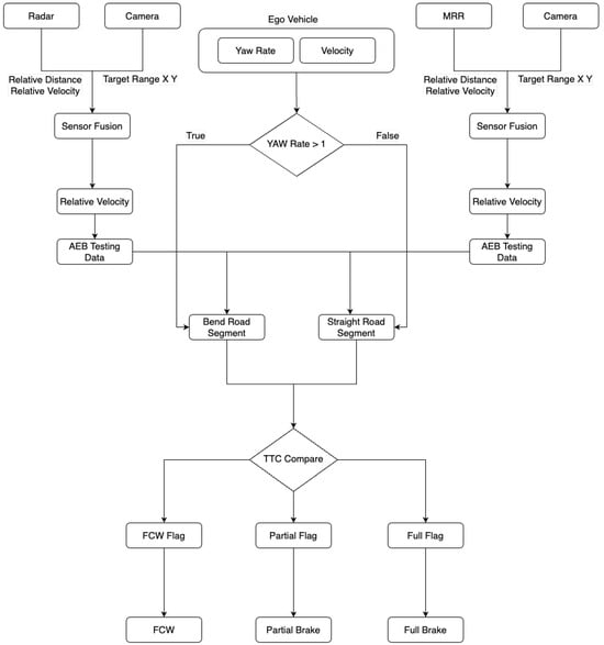
Figure 3.
Data flow diagram.
The diagram illustrates the flow of data and decision-making within an AEB system. It consists of various sensors, data fusion processes, and decision logic that collectively determine the appropriate braking response based on the vehicle’s environment and conditions.
- Ego Vehicle
- This is the central entity, representing the vehicle equipped with the AEB system. It processes inputs from various sensors to determine the required action.
- Inputs include the following:
- –
- Radar: this measures the relative distance and relative velocity of objects in front of the vehicle.
- –
- Camera: this provides target range (X, Y) information.
- –
- Yaw Rate: this monitors the rotation rate of the vehicle around its vertical axis.
- –
- Velocity: this indicates the speed of the vehicle.
- –
- MRR (Mid-Range Radar): similarly to the radar, this provides relative distance and relative velocity data but performs so for a different range.
- Sensor Fusion
- The radar and camera inputs are combined through a sensor fusion process. This fusion is performed separately for two different paths:
- –
- The left path involves the radar and camera, which merge their data to calculate the relative velocity.
- –
- The right path involves the MRR and camera, similarly fusing their data to compute the relative velocity.
- Relative Velocity
- After sensor fusion, the relative velocity is calculated for both paths. This velocity indicates how quickly the distance between the ego vehicle and an object ahead is changing.
- The calculated relative velocities are then passed to the AEB testing data module.
- AEB Testing Data
- The AEB testing data module receives the relative velocity data from both paths.
- This module uses the data to simulate or analyze potential collision scenarios.
- Yaw Rate Decision Block
- The yaw rate is compared against a threshold of 1 (likely representing a significant yaw indicating a sharp turn or lane change).
- Two paths are determined based on the yaw rate:
- –
- True: if the yaw rate is greater than 1, the vehicle is considered on a bent road segment.
- –
- False: if the yaw rate is less than or equal to 1, the vehicle is considered on a straight road segment.
- Road Segment Analysis
- Based on the road segment (bent or straight), the AEB system adapts its testing data:
- –
- Bent Road Segment: the system likely adjusts the AEB testing to account for the dynamics of turning.
- –
- Straight Road Segment: the system processes the data assuming a straightforward path, focusing on linear deceleration.
- Time to Collision (TTC) Comparison
- After processing the road segment data, the system performs a TTC comparison, determining how much time remains before a potential collision.
- Based on the TTC result, the system flags one of three states:
- –
- FCW (Forward Collision Warning) Flag: this indicates that a warning should be issued to the driver, typically when the collision is imminent but avoidable with driver intervention.
- –
- Partial Flag: this indicates that partial braking should be applied, usually in cases where a collision is likely but not imminent.
- –
- Full Flag: this indicates that full braking should be applied immediately, often in cases where a collision is unavoidable without intervention.
- Action Modules
- Based on the flag set by the TTC comparison:
- –
- FCW: the system issues a forward collision warning to alert the driver of an impending collision.
- –
- Partial Brake: the system applies partial braking to reduce speed and avoid collision.
- –
- Full Brake: the system applies full braking force to prevent or mitigate a collision.
4.4. Trust and Security Considerations
- Cluster Trusted Boundary: The diagram highlights a trusted boundary around the cluster, indicating that certain communications or data flows are secured or trusted within this area. This boundary is crucial for maintaining the integrity and security of the AEB system, ensuring that data within this cluster are protected from tampering or unauthorized access.
- Hardwire Connection: this connection suggests an external or possibly less secure communication link, marked with a dotted red line, indicating the need for heightened security measures or monitoring.
4.5. System Design Diagram of Features
An autonomous emergency braking AEB system is an advanced driver-assistance system ADAS designed to automatically detect potential collisions and apply brakes to prevent or mitigate crashes. AEB is crucial for vehicle safety, significantly reducing the likelihood and severity of accidents by responding faster than human drivers to hazards. From a cybersecurity perspective, AEB systems are critical because they rely on sensors, software, and communication networks that are vulnerable to cyber attacks, as discussed by Alsuwian et al. [17]. Compromising an AEB system could lead to unintended braking or failure to brake when needed, posing severe safety risks. Therefore, ensuring robust cybersecurity measures for AEB systems is essential to maintain their reliability and safety, as discussed by Milanes et al. [14].
5. Threat Analysis and Risk Assessment (TARA)
5.1. TARA-ISO 21434
TARA is a key process in ISO/SAE 21434, focusing on identifying, assessing, and prioritizing cybersecurity risks across a vehicle’s lifecycle. It evaluates threats and vulnerabilities, determines impact, and assesses the probability of exploitation, as shown by Kim et al. [7]. In the context of ISO 21434, TARA is integral to several phases, including risk assessment, risk treatment, and continuous monitoring, aligning with the standard’s emphasis on a risk-based approach to cybersecurity, as discussed by Tang et al. [8]. It is the phase for risk identification, which involves identifying assets, threats, and vulnerabilities and establishing the level of risk on a scale based on impact and likelihood. During the risk treatment stage, controls on security are proposed that can reduce such risks to acceptable levels. This study makes propositions for a mitigation strategy without addressing implementation issues for the solution to be globally considered under ISO/SAE 21434 but is in-depth in understanding risks and proposed solutions, thus making proper grounds for future steps toward automotive cybersecurity, as shown by Lu et al. [11].
5.2. Asset Identification
A thorough analysis was performed of all components within the AEB system architecture to identify those that could lead to a damage scenario if compromised. Each component, port, and connection between ports was evaluated for relevant cybersecurity properties, including confidentiality, integrity, and availability. Additionally, elements such as ECUs and sensors were assigned properties of authenticity, non-repudiability, and authorization.
5.3. Threat Scenario Identification
Threat scenarios were identified using Medini Analyze 2024 R1 software, utilizing the STRIDE model as the foundational framework. This model mapped each cybersecurity property—authenticity, integrity, non-repudiability, confidentiality, availability, and authorization—to its corresponding potential threats: spoofing, tampering, repudiation, information disclosure, DoS, and EoP. For each threat scenario identified, three key elements were detailed: the specific asset at risk, the compromised cybersecurity property affecting that asset, and the root cause of the compromise. To determine the cybersecurity properties relevant to each asset, a manual process was conducted. Following this, the software aided in extracting the related threat scenarios linked to these properties.
5.4. Impact Rating
The evaluation of damage scenarios involved a thorough analysis of their effects on road users. The consequences were categorized into four distinct groups: safety (potential injuries or fatalities), financial (the economic impact on the road user), operational (the loss of or reduction in vehicle functionality), and privacy (the sensitivity of the disclosed user information). For each damage scenario and impact category, an impact rating was assigned. The rating scale included four levels of severity, listed in descending order: severe, major, moderate, and negligible.
5.5. Attack Vector Analysis
The attack vector analysis was conducted for each previously identified threat scenario. This analysis outlined the routes that potential adversaries might take to exploit vulnerabilities. For each threat scenario, one or more specific attack paths were identified, detailing the sequence of actions an attacker could use to navigate through the system’s assets. For example, an attack path might start with physical access to the vehicle’s sensor system, proceed to compromise the electronic control unit (ECU), and ultimately tamper with the braking system.
5.6. Attack Feasibility Rating
The attack feasibility rating could be evaluated using one of three approaches: attack potential-based, Common Vulnerability Scoring System (CVSS)-based, and attack vector-based approaches. Due to the limitations in knowledge about the system elements, technologies, and actors at the time of this research and the unavailability of an advanced system architecture design, the attack vector-based approach was utilized.
Criteria for Evaluation
The attack feasibility rating was determined by assessing the predominant attack vector in the attack path. The scale for ratings considered the following aspects:
- Attacker’s Experience: This denotes the level of experience and skill that the attacker possesses. More experienced attackers might find certain vulnerabilities easier to exploit.
- The Ease of Reproducing the Attack: This denotes the complexity involved in replicating the attack. Simpler, more straightforward attacks are rated as more feasible.
- Approach Used: In this research, the attack vector-based approach was applied. This approach evaluates how accessible the attack vector is, considering whether it is network-based, local, adjacent, or physical.
- The Context of the Attack: This rating scale includes the following.
- –
- Network: high feasibility, as remote access via the network is easier and less resource-intensive.
- –
- Adjacent: medium feasibility, involving access from a nearby network or system.
- –
- Local: low feasibility, requiring physical proximity to the asset.
- –
- Physical: very low feasibility, necessitating physical access to the asset, which is often more challenging and less desirable for attackers.
5.7. Risk Value Determination
Risk values were analyzed by applying a sequence of risk formulas that combined impact ratings and attack feasibility ratings. For each specific threat scenario, the average of all impact scores was then calculated and multiplied by the feasibility score which was a score according to the attack vector. The resulting scores were transformed into risk values using predefined mapping. The risk values were classified on a scale, ranked in descending order of severity: high, medium, low, and very low. The impact factor (I) was determined for each feature based on four criteria: safety (S), financial (F), operational (O), and privacy (P), with each having a different weight, with safety being the most influential.
Initially, the potential impact and attack feasibility ratings were converted into corresponding scores. The equation for calculating the risk for each threat scenario is as follows:
Based on ISO 21434, the most important factor is safety; next come financial, operational, and privacy indicators. Such indicators, consistent with the ISO standard, were estimated according to established practices in cybersecurity and safety. Safety was assessed with a surrogate measure that gave a score of possible harm to individuals using methods from the industry standard hazard analysis in order to derive the degree of risk. This approach guaranteed uniformity and consistency in the evaluation of the potential impact and risk for each of the scenarios. The assets were scored according to the table below (Table 3), taking into account ISO 21434.
Table 3.
Risk levels based on lower limit.
5.8. Risk Treatment Descision
The range of potential decisions for risk treatment included mitigation, avoidance, acceptance, and transfer. However, in practice, only mitigation and acceptance were implemented, with avoidance and transfer being excluded from consideration. Avoidance involved abandoning certain essential system features, which were deemed undesirable, while transfer required external entities to manage the risk, a scenario not anticipated. The approach involved mitigating threat scenarios classified as having high and medium risk while accepting those categorized as having low and very low risk. For each identified threat scenario designated for mitigation, a specific set of security measures and corresponding security requirements were developed to reduce or eliminate the associated risk.
6. Risk Analysis
This section presents the findings from the TARA analysis performed of the considered AEB architecture, following the guidelines of the ISO/SAE 21434 standard. As a result, we identified 99 threats distributed across multiple risk levels, as depicted in Figure 4. The analysis was performed by leveraging the STRIDE threat model; Figure 5 clearly outlines that the main components were also severely affected by each of the attacks that composed this threat model.
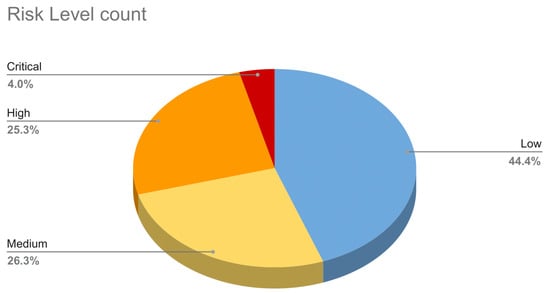
Figure 4.
Distribution of risk levels.
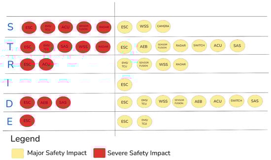
Figure 5.
Discovered threats in our architecture according to the STRIDE threat model.
For each level, an initial analysis is provided in Appendix A.2, detailing associated threats and including significant real-world examples to illustrate potential impacts and implications. Furthermore, the analysis focuses on threats classified within the critical and high-risk levels. In this context, the authors examine the associated security risks and propose effective mitigation measures to address these vulnerabilities. This discussion specifically addresses the threats of tampering, spoofing, and EoP.
Finally, in order to obtain insights about the relevance for the driver and vehicle’s occupants, we also investigated the safety level of these threats.
6.1. Critical-Risk-Level Threats and Mitigation Strategies
After introducing an overview of possible threats in the considered architecture, in this section, we go deeper in discussing a comprehensive examination of the 4.0% of threats classified as critical. Specifically, this analysis focuses on the security risks posed by these threats and the corresponding security measures that can be implemented to mitigate them.
6.1.1. Spoofing of Radar
Security Risk. Spoofing radar poses a critical security vulnerability to AEB systems; it allows attackers to manipulate radar networks by creating phantom objects or masking real ones. This defeats the correct judgment of radars about the environment and hence may lead to hazardous driving conditions, wrong decisions, and accidents. The consequences include damage to vehicles and infrastructure, the disruption of operational vehicles, and safety hazards. Although personal data are not directly impacted, the high potential impact and medium feasibility of such attacks make radar spoofing a critical threat to the integrity and reliability of AEB systems. Security Measures. Key security measures to mitigate radar spoofing risks include performing a risk assessment every month to identify emerging threats and the effectiveness of controls, using strong authentication to block unauthorized access, and checking signal integrity and encryption to verify and protect radar communications. These steps improve the reliability and accuracy of radar systems, ensuring vehicle safety and preventing accidents caused by spoofed data. Together, these strategies greatly reduce the risks of radar spoofing and protect the integrity of AEB systems.
6.1.2. Tampering with EMS/TCU
Security Risk. A lack of protection for the integrity of software in both the EMS/TCU creates significant security vulnerability related to the manipulation of those systems. The nature of this “adjacent” attack vector involves using the OBD port to attack without directly reaching internal systems; an attacker, therefore, may modify critical functions such as the control of the engine and transmission and may thus pose unsafe driving conditions. Although driver privacy remains largely unaffected, the operational, safety, and financial consequences are severe. The overall risk level is assessed as high since the impact is high while the feasibility is medium. Security Measures. Basic forms of security measures regarding EMS/TCU tampering must be implemented to reduce risks. Software updates are required to patch known vulnerabilities that can be used for unauthorized modifications. Monitoring allows the detection of unauthorized changes within the shortest possible time frame to perform corrective actions. In this regard, a quarterly risk review would assess the sufficiency of these measures, adapting them when necessary. Rigorous access control with particular emphasis on critical ports, such as the WSS port, and software integrity checks to allow only authorized modifications prevent tampering with the EMS and TCU. This is all about the security, functionality, and safe operation of the vehicle.
6.1.3. Tampering with WSS_to_ESC_CAN
Security Risks. The manipulation of WSS– and ESC–CAN communication threatens security by tampering with critical vehicle sensors used by safety systems. In general, an attacker physically accesses the vehicle through the OBD connector and can manipulate sensor data, thereby giving wrong information to the ESC system. The AEB system operates in an incorrect manner due to interference and causes accidents or driving in unsafe conditions. The operational impact is severe; vehicle safety is directly compromised, while the privacy concerns are minimal. Due to the potential consequences and medium feasibility of such an attack, the overall risk is classified as high. Ensuring the integrity of WSS and ESC communications is vital for maintaining vehicle safety. Security Measures. Tampering with WSS– and ESC–CAN communication must be minimized through robust security measures regarding the integrity and authenticity of data. The implementation of cryptographic message integrity protection, such as HMAC, ensures that data are not altered without authorization. The strict physical security, for example, of the OBD connector reduces the possibility of unauthorized access, while the auditing of the system and its constant monitoring enable the early detection of tampering. The threat vectors keep evolving with WSS and ESC software updated for the latest threats; quarterly risk reviews should be performed. Software integrity and strict access controls allow only authorized changes to be introduced to these systems.
6.1.4. Elevation of Privilege of EMS/TCU
Security Risk. Performing an elevation-of-privilege attack on the EMS and TCU presents a serious security risk; software vulnerabilities in critical vehicle controls could be exploited for unauthorized access. This is usually accompanied by the extraction of unencrypted data through the ESC system for insight into the operations of the vehicle. An attacker may change the functionality of EMS and TCU once elevated access is granted, which will lead to unsafe driving conditions, system failure, or the total loss of vehicle control, some scenarios that pose grave risks. The financial and operational impact is high in terms of possible repair costs and liabilities. Although privacy concerns are low, overall, the risk is high because of the severe consequences and medium feasibility of these kinds of attacks. Security Measures. Robust security measures should be implemented to mitigate the risk of elevation-of-privilege attacks against the EMS and TCU. Known vulnerabilities in software and hardware should be patched and updated regularly; privilege separation can prevent unauthorized access to critical vehicle controls. Conducting quarterly risk assessments is helpful in identifying and adapting changes in security measures. Regular software updates, MFA, and encrypted communication channels would provide further protection against unauthorized access. These measures are important for the integrity and security of the EMS and TCU, thus ensuring safe vehicle system operations.
6.2. High-Risk-Level Threats and Mitigation Strategies
This subsequent step involves a thorough examination of the threats classified as having high risk. Specifically, this analysis focuses on the security risks associated with these threats and the corresponding security measures that can be implemented to mitigate them effectively.
6.2.1. Elevation of Privilege of ESC
Security Risks. The ESC system is important for vehicle braking and stability; an elevation-of-privilege attack on it presents a huge security risk. Using software vulnerabilities, an attacker with physical proximity—usually through the OBD connector—could obtain unauthorized control over ESC functions. Such an attack could compromise vehicle safety by manipulating braking and stability systems, leading to hazardous driving conditions and increasing the likelihood of accidents. Although the privacy impact is low, the operational and safety consequences are severe, including financial costs from repairs and possible legal issues. This risk is considered high because of the high impact and medium feasibility. Security Measures. Access controls, including MFA and privileged access management, should be implemented to avoid unauthorized access to the ESC system, which would mitigate the security risks of elevation-of-privilege attacks. Regular risk assessments should be carried out to identify vulnerabilities. The presence of comprehensive logging and monitoring mechanisms would help detect unauthorized access attempts. These measures would safeguard the integrity of the ESC system, ensuring the reliability of vehicle stability and braking functions while preventing the unauthorized manipulation of safety controls.
6.2.2. Tampering with Radar_to_ESC_CAN_3
Security Risk. Due to this, the information exchanged between the radar and the ESC system using the CAN communication channel can develop a very serious security breach, as attackers with physical access to the OBD connector would be able to manipulate the radar data. An “adjacent” attack against the AEB system would eventually destroy the proper operation or result in its failure and increase the chance of accidents due to false data. Although privacy is not directly affected, the operational and safety impacts are severe, potentially making the vehicle unsafe to drive. In general, the risk is considerable given the medium feasibility of the attack and its potentially severe consequences. Security Measures. For risk mitigation in regard to tampering with the radar-to-ESC CAN, cryptographic message integrity checks are required, like HMAC, to ensure the authenticity and integrity of radar data. The regular auditing and monitoring of the communication system would help in response and detection against any type of anomalies or unauthorized activities. These measures would also be important in ensuring the integrity of radar data, the reliable performance of the AEB system, and improving general safety through the prevention of accidents occurring as a result of tampered data.
6.2.3. Tampering with Sensorfusion_to_Cluster_CAN
Security Risk. Tampering with sensor fusion-to-cluster CAN communication is a security risk, since attackers with physical access to the vehicle could manipulate data, usually through the OBD. While the main intent of these data is to provide information for the display of the AEB system, malicious manipulation may mislead the driver into unsafe driving conditions. The financial and privacy impacts are negligible, but the operational impact is high, as it disrupts the function of the vehicle. Medium feasibility and moderate safety concerns set the overall risk as medium. Security Measures. To mitigate the risk of manipulation in sensor fusion-to-cluster CAN communication, secure communication protocols like TLS should be implemented to ensure data’s integrity and confidentiality. The regular monitoring and auditing of communication channels can help detect anomalies or unauthorized access, maintaining the accuracy and reliability of the cluster display and ensuring the safe operation of the vehicle.
6.3. Safety Impact Taxonomy
This chapter provides an in-depth cybersecurity risk analysis of the autonomous emergency braking AEB system using the STRIDE methodology. The analysis evaluates and categorizes each AEB component within severe and major safety impact levels, facilitating a structured approach to identifying and mitigating threats that, while not always classified as high-risk, pose critical implications for vehicle safety. This evaluation underscores the necessity of robust security measures to ensure the AEB system’s reliability and the overall safety of vehicle operations.
As outlined in Table 4, the most significant safety threats arise from spoofing, tampering, and denial-of-service attacks on critical components. The ESC system is the most vulnerable component, as attacks targeting it can cause the entire system to malfunction, posing a substantial risk to the safety of vehicle occupants. The ESC plays a central role in system operations, making it a critical single point of failure. Similarly, the SAS, which detects the steering wheel’s position, is another highly sensitive component. In the event of spoofing, the SAS may deliver incorrect data to the ESC, while a denial-of-service attack could prevent it from transmitting data altogether. Both scenarios critically compromise vehicle safety, further underscoring the components’ importance.
Table 4.
Analyzed STRIDE severe threats for safety.
7. Suggested Improvements
The thorough analysis of the AEB system underscored the necessity of implementing strategic improvements to address critical and high-level cybersecurity threats, which, if left unaddressed, could pose serious risks to human safety. Enhancing system resilience against these threats is not only vital for safeguarding vehicle functionality but also for ensuring the protection of end users.
In this section, we outline the main improvements that should be taken into account when developing an AEB system. These recommendations are grouped into three categories: physical security, software advancements, and compliance with standards.
7.1. Physical Security
The physical security of components within the ACU is critical to prevent unauthorized tampering and maintain system integrity. Measures such as restricting access to the ACU and OBD connectors and using tamper-evident seals help mitigate physical attack risks. Additionally, a comprehensive physical security approach includes integrating a gateway to manage and secure communications within the AEB system. The gateway centralizes the management of CAN frames, enforces security policies, and monitors for communication anomalies, ensuring secure interactions between components.
Furthermore, the incorporation of an HSM significantly enhances the security of AEB systems. HSMs provide a secure environment for storing and processing cryptographic keys, thereby protecting the communication between AEB components, as discussed by Pethö et al. [21]. They can be utilized for several critical security functions:
- Robust Authentication: HSMs can manage and protect keys used to authenticate messages between AEB components, ensuring that only trusted sources can send commands. This authentication mechanism is crucial for maintaining the integrity and reliability of the AEB system.
- Data Encryption: HSMs can encrypt sensitive data transmitted between components, making them unreadable to potential attackers intercepting communications. This encryption ensures that even if data are intercepted, they cannot be used maliciously.
By implementing these physical security measures, we can significantly enhance the resilience of the AEB system against physical attacks. Restricting access, using tamper-evident seals, integrating a secure gateway, and utilizing HSMs collectively form a robust physical security framework that safeguards critical components and ensures the overall integrity of the AEB system.
7.2. Software Advancements
One of the key enhancements in software approaches is the usage of an Intrusion Detection System (IDS), as shown by Piątek et al. [20]. It can monitor network traffic in real time for suspicious activities, such as unauthorized access attempts or data manipulation.
- Anomaly Detection: the IDS can be trained to recognize normal traffic patterns for the AEB system and alert it to deviations that might indicate an attack.
- Rapid Response: in the event of malicious activity detection, the IDS can trigger rapid response measures, such as isolating compromised components or halting suspicious communications.
Other approaches aimed at enhancing the overall security of AEB system components, such as the Electronic Stability Control ESC and Engine Management System EMS are related to regular software updates to patch known vulnerabilities.
- Secure Update Mechanisms: this involves implementing secure update mechanisms to ensure that software updates come from trusted sources and are not tampered with.
- Thorough Testing: this involves rigorously testing software updates before deployment to avoid compatibility issues or new vulnerabilities.
- Controlled Communication: The gateway can facilitate controlled communication by managing the CAN frames sent between AEB components, ensuring that only authorized and properly formatted messages are transmitted. This prevents unauthorized devices from injecting malicious frames into the network.
- Traffic Monitoring: By monitoring the CAN traffic passing through the gateway, potential threats can be detected early. The gateway can analyze frame patterns and identify anomalies, such as unexpected frame types or transmission rates, enabling prompt action to mitigate risks.
- Protocol Translation: The gateway can support different communication protocols, including the CAN, to ensure seamless interoperability between various components. It can convert CAN frames to other protocols used in the architecture, allowing diverse components to communicate effectively while maintaining the integrity of the data.
- Error Handling and Frame Validation: The gateway can implement error handling mechanisms to ensure the reliability of communication. It can validate incoming CAN frames against predefined criteria, rejecting frames that do not meet security or functional requirements.
- Logging and Auditing: The gateway can log all CAN traffic for auditing purposes, providing a record of communication events. These data can be used to analyze potential security incidents or to verify compliance with established protocols.
7.3. Compliance with ISO/SAE 21434 and ISO 24089 Standards
Achieving and maintaining adherence to ISO/SAE 21434 and ISO 24089 is essential for automotive cybersecurity, as these standards provide a framework to manage cyber risks across a vehicle’s lifecycle. This requires integrating security measures into every phase of vehicle system design, development, and maintenance to ensure the safety and resilience of automotive systems [5].
- Lifecycle-Based Cybersecurity ManagementTo comply with ISO/SAE 21434, manufacturers must implement a structured, lifecycle-oriented approach to cybersecurity management. This entails integrating cybersecurity objectives and threat modeling from the concept phase and refining them throughout the design, development, production, operation, and decommissioning phases. Each phase should include specific cybersecurity assessments and documented security objectives tailored to its unique risks. This approach not only facilitates traceability and accountability but also enhances the overall resilience of vehicles against evolving cybersecurity threats.
- Risk Assessment and Mitigation PlanningAn ongoing and thorough risk assessment is crucial for identifying cybersecurity vulnerabilities and ensuring compliance with ISO/SAE 21434 [4]. Manufacturers should conduct regular evaluations for each vehicle component, such as AEB systems and infotainment units, to assess their security impact. A continuously updated, component-specific threat model should incorporate new risks, field data, and changes in the threat landscape. Effective mitigation planning involves implementing prioritized preventive and corrective actions, ensuring that the cybersecurity framework adapts to technological advancements and enhances vehicle resilience.
- Secure Software Update MechanismsISO 24089 emphasizes the importance of securing software updates for automotive cybersecurity. Manufacturers must implement reliable update mechanisms for both OTA and in-dealership updates, utilizing encryption, cryptographic authentication, and verification protocols to prevent unauthorized access or tampering. Compliance with ISO 24089 requires that only authorized and authenticated updates are deployed, effectively blocking unauthorized code or malicious modifications. This process should be rigorously tested and integrated into the overall cybersecurity strategy to enhance the vehicle’s security framework [5].
- Component-Level Cybersecurity PracticesManufacturers must perform regular vulnerability testing and validation for each component to ensure compliance with security standards. This includes both automated and manual methods, such as penetration testing, static and dynamic analysis, and component-specific threat modeling. The early identification of vulnerabilities allows for risk mitigation before integration into the larger system. Additionally, ensuring that each component meets security requirements reinforces the overall cybersecurity posture of the AEB system, contributing to the vehicle’s integrity.
- Compliance Audits and Continuous MonitoringCompliance audits should systematically assess adherence to ISO/SAE 21434 and ISO 24089 standards, focusing on system integrity, update mechanisms, and incident response protocols. Conducting these audits regularly—such as quarterly or bi-annually—enables manufacturers to track compliance status and identify improvement areas. Continuous monitoring involves deploying real-time surveillance mechanisms to detect potential threats and vulnerabilities. This proactive strategy allows for the early identification of anomalies, facilitating prompt responses to security issues. Manufacturers should leverage automated monitoring tools and threat intelligence feeds to ensure that their systems are aligned with the evolving threat landscape.
- Collaborative Development of Security ProtocolsAutomotive manufacturers should facilitate collaboration between software developers, hardware engineers, and cybersecurity experts in the implementation of ISO standards during the whole lifecycle of the vehicle. The early involvement of cybersecurity professionals ensures the integration of security measures and the identification of vulnerabilities. Standardized protocols for data handling, access control, and encryption, such as RBAC, are important. Regular feedback loops and updates of protocols improve security and address emerging threats, enhancing risk mitigation.
- Training and Skill Development in Cybersecurity StandardsManufacturers have to invest in target training in software, hardware, and cybersecurity teams regarding ISO/SAE 21434 and ISO 24089 [4,5] Training on threat modeling, secure software development, incident response planning, and regular workshops with current security practices or certifications are important. This is where collaboration on certifications with cybersecurity organizations validate the employees. This also creates a culture of compliance wherein proactive steps to improve the security posture of an organization are taken.
- Metrics and Benchmarking for Security PerformanceEstablishing KPIs is essential for assessing the effectiveness of cybersecurity practices in accordance with ISO standards. Manufacturers should define metrics that track security incidents, vulnerability remediation times, and employee training participation. Regular assessments enable benchmarking against industry standards, helping to identify gaps and areas for improvement. By utilizing these metrics, manufacturers can refine their cybersecurity strategies, enhancing compliance with ISO standards and fostering a resilient cybersecurity framework that adapts to the evolving automotive landscape.
By applying these structured approaches to cybersecurity management, software update mechanisms, and ongoing compliance evaluation, the automotive sector can achieve consistent and thorough adherence to ISO/SAE 21434 and ISO 24089, thus building a robust foundation for secure AEB and other safety-critical automotive systems.
8. Conclusions
This security analysis of the AEB system reveals critical insights into the cybersecurity challenges and considerations associated with this advanced safety technology. As AEB systems become increasingly integral to modern vehicles, understanding their security threats and implementing effective security measures against those threats is essential to ensuring the security and safety of road vehicle users.
To answer the first research question, the analysis identifies the core components of a typical AEB system. The components that are included in the architecture are the AEB cluster, radar, camera, sensor fusion, EMS/TCU, SAS, ACU, WSS, ESC, vehicle lamp, and brake system. These components are interconnected through various communication channels, including in-vehicle networks such as the CAN and hardwired connection, which facilitate the transfer of information required for real-time decision-making. Precisely, in our scenario, we have a hardwired connection between the EMS and WSS and the same for the vehicle lamp. Enhanced encryption for data transmission, secure coding practices, and robust access controls is required to address several security threats and risks effectively. However, even with these measures, some low-level residual risks remain, mainly due to a lack of resources, indicating the need for the ongoing surveillance and iterative improvement of security strategies.
Moreover, as discussed in Section 7, implementing the suggested improvements will enable the development of a real architecture that further enhances the security posture of AEB systems; by incorporating these enhancements, future designs can mitigate residual risks more effectively and ensure a higher level of safety and reliability for all road vehicle users.
Author Contributions
Conceptualization, R.K.; Data Curation, U.D.M. and B.B.; Investigation, M.P.T., U.D.M. and K.-A.M.; Methodology, B.B., R.K. and U.D.M.; Supervision, C.E., R.K. and B.B.; Validation, R.K.; Writing—Original Draft, B.B., K.-A.M., M.P.T. and U.D.M.; Writing, Review and editing, B.B. All authors have read and agreed to the published version of the manuscript.
Funding
This research work was completed by the on-site participants of the third version of the Automotive Cybersecurity Academy (ACSA) 2024 (Weblink of ACSA 2024: https://www.autocybersec.ro/all-acsas/acsa-2024 accessed on 18 January 2025) which is funded by the European Commission as part of the Erasmus+ Blended Intensive Program (BIP). Led by Prof. Dr. Rahamatullah Khondoker, students, teachers, and researchers from the following universities and industries contributed in the BIP: University of Salerno in Italy, Technische Hochschule Mittelhessen in Germany, Politehnica University of Timişoara in Romania, University Politehnica of Bucharest in Romania, Hochschule Darmstadt in Germany, Technische Hochschule Ingolstadt in Germany, Continental Automotive Romania, CES Automotive in Germany, SAPAR in Germany, ARRK Europe Limited in Germany, HORIBA MIRA in the UK, and STMicroelectronics in Italy.
Institutional Review Board Statement
Not applicable.
Informed Consent Statement
Not applicable.
Data Availability Statement
The original contributions presented in the study are included in the article, further inquiries can be directed to the corresponding author.
Acknowledgments
This work was performed in an Erasmus+ Blended Intensive Program BIP titled the Automotive Cybersecurity Academy (ACSA) that was held at the University of Salerno, Italy, from 22 August 2024 to 4 September 2024. We would like to acknowledge all other contributors to this paper, Antonio Correia, Arbinda Pokharel, Axit Kakadiya, Bogdan-Radu Preda, Gianpaolo Laurenzano, Linta Joseph, and Pedro Martin, who supported us throughout our project. We express appreciation to ANSYS and CADFEM Germany for providing us the free access of Ansys Medini Analyze. The work of the first and second ACSA are published in MDPI journals [22,23].
Conflicts of Interest
The authors declare no conflicts of interest.
Abbreviations
| ACU | Airbag Control Unit |
| ADAS | Advanced driver-assistance systems |
| AEB | Autonomous emergency braking |
| BIP | Blended Intensive Program |
| CAN | Controller Area Network |
| DoS | Denial of service |
| ECU | Electronic control unit |
| EMS | Engine management system |
| EoP | Elevation of privilege |
| ESC | Electronic Stability Control |
| ETH | Ethernet |
| ETTC | Enhanced time-to-collision |
| FOPS | Financial Operational Privacy Security |
| HARA | Hazard analysis and risk assessment |
| HIL | Hardware-in-the-loop |
| HMAC | Hash-based Message Authentication Code |
| HSM | Hardware Security Module |
| ISO | International Organization for Standardization |
| KPI | Key Performance Indicator |
| MFA | Multi-factor authentication |
| MTM | Microsoft Threat Modeling Tool |
| OBD | On-Board Diagnostics |
| OEM | Original equipment manufacturer |
| OTA | Over-the-air |
| SAE | Society of Automotive Engineers |
| SAS | Steering angle control |
| STRIDE | Spoofing; tampering; repudiation; information disclosure; denial of service; elevation of privilege |
| TARA | Threat analysis and risk assessment |
| TCU | Telematics control unit |
| TLS | Transport Layer Security |
| TTC | Time-to-collision |
| V2I | Vehicle-to-infrastructure |
| V2V | Vehicle-to-vehicle |
| V2X | Vehicle-to-everything |
| WSS | Wheel Speed Sensor |
Appendix A
Appendix A.1. System Design Model Flow Chart from Ansys Medini

Figure A1.
System design model flow chart.
Figure A1.
System design model flow chart.

Appendix A.2. Risk Taxonomy
Table A1.
Risk taxonomy overview (critical).
Table A1.
Risk taxonomy overview (critical).
| Risk Level | Threat Type | Description |
|---|---|---|
| Critical (4.0%) | Tampering | One of the worst scenarios involves a lack of software integrity, which allows for unauthorized changes. From a practical perspective, this is translated to physical access through the OBD connection. At this point, an attacker can tamper with the EMS and TCU components and modify the behaviour of these components, such as inadvertently stopping the car or causing a much more severe air bag explosion. This threat is critical because it directly impacts the safety and functionality of the vehicle, potentially causing erratic or dangerous vehicle behaviour, leading to accidents or injury, or even being fatal. |
| Elevation of Privilege | From a compromised EMS, an attacker may unlock additional levels of privilege by acquiring a secret key from plain text located in the EMS/TCU. This threat can be executed over the CAN channel from the EMS. Such elevated access may enable the attacker to disable essential safety features, including anti-lock brakes and traction control, thereby compromising vehicle operations and creating unsafe driving conditions. | |
| Spoofing | The use of devices that emit radio frequency signals to mimic the reflections of real objects represents a critical risk. The interference can lead to vehicle misinterpreting its surroundings, resulting in abrupt braking, steering into obstacles, and severe accidents that endanger lives. A deeper analysis will be provided in the next section. |
Table A2.
Risk taxonomy overview (high).
Table A2.
Risk taxonomy overview (high).
| Risk Level | Threat Type | Description |
|---|---|---|
| High (25.3%) | Tampering | Access to the radar system could be achieved by an attacker through specific entry points, such as the vehicle’s OBD port, which connects directly to the in-vehicle CAN. This access allows the interception, alteration, or injection of malicious CAN messages between the radar and ESC, thereby compromising the vehicle’s interpretation of road conditions. |
| Denial of Service | An attacker may exploit the radar sensor by inundating its input with excessive or malformed data packets, thereby impairing the sensor’s ability to process legitimate signals. This disruption can result in a failure to transmit critical information regarding the vehicle’s environment to the sensor fusion component, consequently hindering its capacity to accurately integrate data from multiple sensors. As a result, the ability of the vehicle to provide functional information can be compromised, increasing the risk of unsafe driving conditions. | |
| Spoofing | Malicious data packets can be injected into the Controller Area Network CAN communication through the On-Board Diagnostics OBD connection, representing a common method for spoofing the Electronic Stability Control ESC system. This attack enables the attacker to manipulate the ESC’s behaviour by sending false signals, which can disrupt the vehicle’s stability and safety functions. | |
| High (25.3%) | Repudiation | Bypassing and disabling the critical authentication and logging mechanisms of the Electronic Stability Control ESC component allows an attacker to deny the execution of unauthorized commands or modifications to the ESC. Additionally, an attacker can alter the input data from the sensors connected to the ESC, thereby facilitating the repudiation of responsibility for the actions taken by the vehicle. This manipulation undermines accountability and complicates incident investigations, hindering the accurate attribution of malicious actions to the perpetrator. |
| Elevation of Privilege | Accessing the firmware of the ESC system constitutes a critical vulnerability that an attacker could exploit to introduce backdoors or bypass existing security controls. Through firmware modification, the attacker could manipulate the ESC’s operational parameters and logic, facilitating the execution of unauthorized commands with elevated privileges. This operation poses substantial risks to vehicle safety, as it enables a potential alteration in vital stability functions and responses to various driving conditions. | |
| Information Disclosure | Due to the identified lack of integrity in the firmware, the consequences of this threat may allow the attacker to obtain a substantial amount of sensitive information from the CAN channel. This deficiency indicates that there is no encryption between the ESC component and other sensors responsible for processing critical data or information. |
Table A3.
Risk taxonomy overview (medium).
Table A3.
Risk taxonomy overview (medium).
| Risk Level | Threat Type | Description |
|---|---|---|
| Medium (26.3%) | Denial of Service | An attacker may initiate a denial of service by transmitting an excessive volume of data to the CAN channel, exploiting the absence of a rate limiter on the radar sensor. This overload disrupts the radar’s functionality, leading to an interruption in its service and impairing the system’s overall performance. |
| Information Disclosure | A malicious entity could exploit this information disclosure vulnerability by intercepting CAN messages through a device connected to accessible vehicle interfaces, such as the OBD port, or by obtaining unauthorized access to in-vehicle network interfaces. By utilizing these entry points, the attacker may perform packet-sniffing operations to capture and analyze CAN communications, exposing critical AEB data related to braking parameters, speed, or sensor information. These sensitive data, once disclosed, could be used to infer or manipulate AEB responses, potentially compromising vehicle operations or facilitating additional targeted attacks. | |
| Repudiation | The exploitation of the Electronic Management System EMS component can enable an attacker to manipulate the status of the brake lamp. By generating unauthorized commands that traverse the Controller Area Network CAN associated with the Electronic Stability Control ESC, the malicious entity can activate or deactivate the brake lamps without creating traceable evidence. This lack of accountability poses significant risks, as it allows the perpetrator to repudiate responsibility for actions taken by the vehicle, ultimately endangering the safety of other road users. | |
| Medium (26.3%) | Tampering | An attacker may gain physical access to the vehicle by breaking into it or exploiting unlocked doors. Once inside, the attacker can remove dashboard panels to directly manipulate the AEB switch or its wiring, causing it to malfunction or behave unexpectedly. Additionally, the attacker could alter connections to the sensor fusion module, disrupting the data flow from the radar, which is crucial for the AEB’s operational integrity. This manipulation can lead to false readings or even disable the AEB system entirely, resulting in compromised safety and an increased risk of collisions. |
| Spoofing | From an external environment, an attacker can inject malicious data into the CAN channel connecting the ACU and the ESC system. This exploitation may involve using a compromised device, such as a rogue OBD dongle or a Bluetooth-enabled interface, capable of interfacing with the vehicle’s communication network. By leveraging known vulnerabilities within the vehicle’s CAN bus protocols, the attacker can transmit unauthorized commands or deceptive information to the ESC. Such spoofing attacks have the potential to manipulate critical vehicle functions, including an alteration in braking responses and the modification of stability control parameters, thereby compromising vehicle safety and increasing the risk of hazardous driving conditions. |
Table A4.
Risk taxonomy overview (low).
Table A4.
Risk taxonomy overview (low).
| Risk Level | Threat Type | Description |
|---|---|---|
| Low (19.9%) | Information Disclosure | An attacker could exploit this vulnerability by accessing the CAN via interfaces like the OBD port. Once connected, the attacker may employ packet-sniffing tools to intercept CAN messages between the EMS and TCU, gaining access to sensitive information such as vehicle operational parameters, diagnostic trouble codes, and real-time performance metrics. While these data do not directly compromise critical vehicle control systems or present immediate safety risks, they can be leveraged for further attacks, thereby posing a significant security concern. |
| Spoofing | By injecting fraudulent data into the Controller Area Network CAN bus, an attacker can spoof the readings from the Wheel Speed Sensor WSS, resulting in the ESC system receiving inaccurate information regarding the actual wheel speed. While this manipulation does not immediately compromise vehicle safety, it can affect the stability control responses, potentially impairing the vehicle’s ability to maintain control during critical driving situations. Erroneous WSS data may lead to suboptimal braking or traction control interventions, posing a moderate risk to the safety of the vehicle and its occupants. | |
| Repudiation | An attacker may exploit the repudiation threat associated with the Wheel Speed Sensor WSS by connecting a rogue device to the Controller Area Network CAN. This connection allows for the interception and modification of messages exchanged between the WSS and the ESC system. By injecting forged or altered messages, the attacker can create discrepancies in the reported wheel speed data. While this manipulation may not result in immediate critical failures, it enables the attacker to deny responsibility for unauthorized actions taken by the vehicle, obscuring the true operational state of the WSS. Consequently, the ESC may receive inaccurate information, which could hinder its ability to implement effective stability control measures, potentially compromising vehicle safety and leading to hazardous driving conditions. | |
| Low (19.9%) | Tampering | By gaining physical access, an attacker can manipulate the wiring or connectors that connect the SAS to the radar, potentially introducing unauthorized devices or modifying signal transmissions. This manipulation may involve inserting a rogue device into the CAN bus, which can intercept and alter messages exchanged between the SAS and the radar sensor. |
| Denial of service | If the steering angle sensor SAS contains known vulnerabilities, these weaknesses may be exploited by an attacker to introduce malware into the system. Once activated, the malware can interfere with the message handling process within the SAS, resulting in excessive traffic in the Controller Area Network CAN bus or obstructing the transmission of legitimate data. While this disruption does not pose an immediate threat to vehicle safety, it can compromise communication between critical components, potentially impairing the overall functionality of the vehicle’s control systems. |
References
- Meléndez-Useros, M.; Jiménez-Salas, M.; Viadero-Monasterio, F.; Boada, B.L. Tire Slip H Control for Optimal Braking Depending on Road Condition. Sensors 2023, 23, 1417. [Google Scholar] [CrossRef] [PubMed]
- Viadero-Monasterio, F.; Meléndez-Useros, M.; Jiménez-Salas, M.; Boada, B.L. Robust Adaptive Heterogeneous Vehicle Platoon Control Based on Disturbances Estimation and Compensation. IEEE Access 2024, 12, 96924–96935. [Google Scholar] [CrossRef]
- Gao, J.; Tian, J.; Gong, L.; Zhang, Y. An Innovative Cooperative Driving Strategy for Signal-Free Intersection Navigation with CAV Platoons. Appl. Sci. 2024, 14, 3498. [Google Scholar] [CrossRef]
- ISO/SAE 21434:2021; Road Vehicles—Cybersecurity Engineering. International Organization for Standardization: Geneva, Switzerland, 2021. Available online: https://www.iso.org/standard/70918.html (accessed on 16 December 2024).
- ISO/SAE 24089:2023; Road Vehicles—Software Update Engineering. International Organization for Standardization: Geneva, Switzerland, 2023. Available online: https://www.iso.org/standard/77796.html (accessed on 27 January 2025).
- Ye, Y.; Zhao, J.; Wu, J.; Zhu, B.; Deng, W.; Chen, X. Real-Time Automatic Test of AEB with Brake System in the Loop; Technical report SAE Technical Paper; SAE International: Warrendale, PA, USA, 2018. [Google Scholar]
- Kim, J.H.; Lee, J.H.; Choi, J.H.; Jeon, W.J. AEB Simulation Method Based on Vehicle Test Data for Accident Analysis of ADAS Vehicles. Int. J. Automot. Technol. 2024, 25, 261–277. [Google Scholar] [CrossRef]
- Tang, B.; Chien, S.; Huang, Z.; Chen, Y. Pedestrian protection using the integration of V2V and the Pedestrian Automatic Emergency Braking System. In Proceedings of the 2016 IEEE 19th International Conference on Intelligent Transportation Systems (ITSC), Rio de Janeiro, Brazil, 1–4 November 2016; pp. 2213–2218. [Google Scholar] [CrossRef]
- Agirre, I.; Calderon A., J.; Yarza, I.; Mugarza, I.; Garcia, D.; Borracci, L.; Uven, P.; Jover, A. UP2DATE software updating framework compliance with safety and security regulations and standards. In Proceedings of the 2023 26th Euromicro Conference on Digital System Design (DSD), Golem, Albania, 6–8 September 2023; pp. 399–406. [Google Scholar] [CrossRef]
- ISO/IEC 27001:2022; Cybersecurity and Privacy Protection—Information Security Management Systems-Requirements. International Organization for Standardization: Geneva, Switzerland, 2022. Available online: https://www.iso.org/standard/27001 (accessed on 27 January 2025).
- Lu, K.-L.; Chen, Y.-Y. ISO 26262 ASIL-Oriented Hardware Design Framework for Safety-Critical Automotive Systems. In Proceedings of the 2019 IEEE International Conference on Connected Vehicles and Expo (ICCVE), Graz, Austria, 4–8 November 2019; pp. 1–6. [Google Scholar] [CrossRef]
- Ariyanto, M.; Haryadi, G.D.; Munadi, M.; Ismail, R.; Hendra, Z. Development of Low-Cost Autonomous Emergency Braking System (AEBS) for an Electric Car. In Proceedings of the 2018 5th International Conference on Electric Vehicular Technology (ICEVT), Surakarta, Indonesia, 30–31 October 2018; pp. 167–171. [Google Scholar] [CrossRef]
- ISO 26262-1:2018; Road Vehicles—Functional Safety. International Organization for Standardization: Geneva, Switzerland, 2018. Available online: https://www.iso.org/obp/ui/en/#iso:std:68383:en (accessed on 27 January 2025).
- Milanes, V.; Onieva, E.; Pérez Rastelli, J.; Simó, J.; Gonzalez, C.; Pedro, T. Making Transport Safer: V2V-Based Automated Emergency Braking System. Transport 2011, 26, 290–302. [Google Scholar] [CrossRef]
- Ferenc, G.; Timotijević, D.; Tanasijević, I.; Simić, D. Towards Enhanced Autonomous Driving Takeovers: Fuzzy Logic Perspective for Predicting Situational Awareness. Appl. Sci. 2024, 14, 5697. [Google Scholar] [CrossRef]
- Dewa, A.N.D.; Wahyunggoro, O.; Nugroho, P. Prototype of Automatic Braking System on Car Model Using Fuzzy Logic. In Proceedings of the 2019 International Conference on Sustainable Engineering and Creative Computing (ICSECC), Bandung, Indonesia, 20–22 August 2019; pp. 369–374. [Google Scholar] [CrossRef]
- Alsuwian, T.; Saeed, R.B.; Amin, A.A. Autonomous Vehicle with Emergency Braking Algorithm Based on Multi-Sensor Fusion and Super Twisting Speed Controller. Appl. Sci. 2022, 12, 8458. [Google Scholar] [CrossRef]
- Kopetz, H.; Poledna, S. Autonomous Emergency Braking: A System-of-Systems perspective. In Proceedings of the 2013 43rd Annual IEEE/IFIP Conference on Dependable Systems and Networks Workshop (DSN-W), Budapest, Hungary, 24–27 June 2013; pp. 1–7. [Google Scholar] [CrossRef]
- Zhang, S.; Lei, B.; Chen, S.; Sha, L. Research on subjective evaluation method of automatic emergency braking (AEB) for passenger car. E3S Web Conf. 2021, 268, 01037. [Google Scholar] [CrossRef]
- Piątek, P.; Mydłowski, P.; Buczacki, A.; Moskwa, S. Concept of Using the MBSE Approach to Integrate Security Patterns in Safety-Related Projects for the Automotive Industry. IEEE Trans. Intell. Transp. Syst. 2024, 25, 15477–15492. [Google Scholar] [CrossRef]
- Pethö, Z.; Kazár, T.M.; Kraudy, R.; Szalay, Z.; Török, A. Considering PKI safety impact on network performance during V2X-based AD/ADAS function development processes. In Proceedings of the 2022 IEEE 1st International Conference on Cognitive Mobility (CogMob), Budapest, Hungary, 12–13 October 2022; pp. 000135–000140. [Google Scholar] [CrossRef]
- Tany, N.S.; Suresh, S.; Sinha, D.N.; Shinde, C.; Stolojescu-Crisan, C.; Khondoker, R. Cybersecurity Comparison of Brain-Based Automotive Electrical and Electronic Architectures. Information 2022, 13, 518. [Google Scholar] [CrossRef]
- Boi, B.; Gupta, T.; Rinhel, M.; Jubea, I.; Khondoker, R.; Esposito, C.; Sousa, B.M. Strengthening Automotive Cybersecurity: A Comparative Analysis of ISO/SAE 21434-Compliant Automatic Collision Notification (ACN) Systems. Vehicles 2023, 5, 1760–1802. [Google Scholar] [CrossRef]


Disclaimer/Publisher’s Note: The statements, opinions and data contained in all publications are solely those of the individual author(s) and contributor(s) and not of MDPI and/or the editor(s). MDPI and/or the editor(s) disclaim responsibility for any injury to people or property resulting from any ideas, methods, instructions or products referred to in the content. |
© 2025 by the authors. Licensee MDPI, Basel, Switzerland. This article is an open access article distributed under the terms and conditions of the Creative Commons Attribution (CC BY) license (https://creativecommons.org/licenses/by/4.0/).