Article

Loss Research and Thermal Analysis of BLDC Hollow-Cup Motor Under Reactor Suppression

1
School of Control and Mechanical Engineering, Tianjin Chengjian University, Tianjin 300384, China
2
Tianjin Internal Combustion Engine Research Institute, Tianjin 300072, China
*
Author to whom correspondence should be addressed.
Appl. Sci. 2025, 15(3), 1523; https://doi.org/10.3390/app15031523
Submission received: 25 December 2024 / Revised: 26 January 2025 / Accepted: 31 January 2025 / Published: 2 February 2025

Abstract

:
In order to avoid overheating of a BLDC permanent magnet (PM) motor at high speeds, this paper focuses on the loss reduction of a 90 W 47,000 r/min BLDC hollow-cup motor. It is proposed to provide an optimizing method for the series reactors and the parameterization of reactors in the motor system. The finite element method (FEM) is used to calculate and analyze the time harmonic of air-gap magnetic flux density, stator core loss, and rotor eddy current loss in two cases: with a series reactor and without a reactor. By parameterizing the inductance value, the optimal resistance value is determined to minimize motor loss. In addition, an electromagnetic–thermal coupling analysis is conducted, and the results show that the temperature distribution of the stator core, winding, and rotor are improved under reactor suppression. Finally, an experimental platform is built to verify the temperature increase and the efficiency of the motor load operation. A clear reference for the research and optimization analysis of motor loss reduction is provided.

1. Introduction

BLDC hollow-cup motors are in high demand for unmanned aerial vehicles (UAV), ventilators, and robotic arm applications owing to their high efficiency, low cost, high speed, and other significant characteristics. BLDC hollow-cup motors are different from other types of motors, through which the toothless structure enables the cogging effect of the motor to be suppressed [1]. However, the small armature inductance of BLDC motors cannot effectively suppress current-time harmonics, which leads to increased core loss, reduced efficiency, and higher operating temperatures [2]. In this study, due to the high speed and the current harmonic of the BLDC motor, the significant loss and over-temperature of the BLDC motor is the urgent problem, leading to the irreversible demagnetization of PMs and even to the failure of the motor.
Feng and Yoshida [3,4] proposed the use of special materials, such as amorphous magnetic materials (AMM) and nanocrystalline magnetic materials (NMM), as core elements for high-speed motors to reduce the core losses. A new type of BLDC motor is investigated in Ref. [5]; its stator and rotor are made of soft magnetic composite (SMC) cores, which reduce eddy current losses and increase motor efficiency. The core loss of the segmented stator core is further reduced by applying a corner radius to each tooth root [6]. The literature [7,8] proposes methods to reduce core losses and cogging torque by optimizing the rotor shape of high-speed permanent magnet synchronous motors (PMSMs). The use of molded transposed windings in PMSMs is described in Ref. [9]. This type of winding reduces the copper loss of the motor, to some extent. Z. Zhang et al. investigated the effects of the winding arrangement and core material on iron loss for high-speed switching motor reluctance [10]. L.Y. and Z. F [11] proposed a split-phase winding method for a HSPMM (high-speed permanent magnet motor) which reduces the rotor eddy current losses. Ref. [12] analyzed the effect of copper shielding on eddy current losses in high-speed PMSMs.
Moreover, the current harmonic magnetic field causes eddy current loss in the rotor, and excessive eddy current losses can lead to an increase in temperature. In the study of the effect of time harmonics on electromagnetic losses, Ref. [13] focused on a surface-mounted high-speed PMSM that uses segmented permanent magnets to reduce eddy current losses in the rotor. Minh and Quoc [14] designed a high-speed PMSM with closed slots that significantly reduced the 11th and 13th harmonics of the air-gap flux density, resulting in a reduction in rotor eddy current losses. Im and Gu [15] proposed an optimized current switching and harmonic elimination scheme based on 7th harmonic current injection for trapezoidal BLDC motors to reduce losses and improve efficiency. Vafaie M. H. et al. proposed the use of Halbach array permanent magnet configurations in brushless DC motors to eliminate reverse electromotive force harmonics and reduce losses [16]. A BLDC motor control scheme is proposed in Ref. [17], where the loss is reduced by current harmony, and its negative effects are minimized. Khazaae et al. analyzed the additional electromagnetic losses in the motor during inverter power supply [18]. The analyzed results show that the current time harmonic and stator slotting are the main reasons for the increase in electromagnetic losses.
In this paper, based on previous research, this study takes a high-speed BLDC motor as the research subject. In order to improve efficiency, it is important to study the loss under reactor suppression by using FEA on the magnetic–thermal coupling. The key innovations in this paper are as follows: by changing the system inductance value and analyzing its effect on motor loss and temperature, a method involving a reactor in series between a BLDC hollow-cup motor and a controller is proposed. Through this method, the core loss and rotor eddy current loss can be effectively suppressed. And finally, the experimental platform using a BLDC motor is built to verify the accuracy of the simulation results by measuring the efficiency and temperature rise of the prototype.
The research content and innovativeness of this paper is presented in Section 1. Section 2 presents the main structure and rated parameters of the motor. The optimization method is proposed in Section 3, which mainly analyzes the characteristics of the motor core loss, voltage, current, rotor loss, etc., based on the reactors with different inductance parameters. Section 4 verifies the effectiveness of the optimization content by performing an electromagnetic field-temperature field coupling on the motor. In Section 5, the performance and temperature increase of the optimized prototype are measured. The measured results are compared with the feasibility and accuracy of the optimization method. Section 6 provides the conclusions of the paper.

2. BLDC Hollow-Cup Motor Structure

In this paper, a 90 W 47,000 r/min BLDC hollow-cup motor is presented. The 3D-sectional view of the motor structure is presented in Figure 1. The stator of this motor consists of ring-shaped, toothless silicon steel and a hollow-cup winding. This structure greatly reduces the influence of the cogging effect, reduces the overall size of the motor, and increases the power density. The rotor is made of ring PM, and the PM material is NdFeB. The motor parameters are listed in Table 1.

3. Improvement Design Study

3.1. Theoretical Foundation

When a controller is used to power a BLDC hollow-cup motor, a current time harmonic is present in the motor winding, generating an armature magnetomotive force harmonic. The current time harmonic I k is shown by Equation (1). The frequency f k of the k th time current harmonic and the amplitude of the k th armature magnetomotive force harmonic generated by the v th current time harmonic are shown by Equations (2) and (3) [16], where f 1 is the controller output current in the fundamental frequency, and k is the order of the current time harmonic [16].
I k = U k 2 π f k L a ,
f k = k f 1 ,
F k , v = 3 2 π v p N k w v I k ,
where U k is the voltage time harmonic; f k is the current time harmonic frequency. The amplitude of the current time harmonic depends mainly on the armature inductance L a . F k , v is the k th harmonic amplitude of the armature magnetomotive force generated by the current time harmonic, p is the number of motor pole pairs, k w v is the winding factor for the v th harmonic of the armature’s magnetic potential, and I k is the RMS value of the k th current time harmonic.
Not counting the saturation of the magnetic field, the amplitude of the armature magnetomotive force harmonic is proportional to the amplitude of its corresponding generated magnetic field, expressed as follows:
B k , v F k , v .
According to the law of magnetic induction, the induced electromotive force E k , v generated in the iron core is related to the magnetic field amplitude, the alternating frequency f k , v _ r , as shown in Equation (5). According to Ohm’s law, the eddy current I k , v in the core is proportional to its induced electromotive force E k , v . According to Joule’s law, the eddy current loss P k , v generated by I k , v in the core is proportional to the square of the amplitude of I k , v [16]. These relationships are shown as follows:
E k , v B k , v × f k , v _ r ,
I k , v E k , v ,
P k , v I 2 k , v .
Analysis of the above equations shows that the armature inductance L a is inversely proportional to the current time harmonic I k . The amplitude of the current time harmonic I k is proportional to the amplitude of the armature magnetomotive force harmonic F k , v , and the eddy current loss P k , v is proportional to F k , v [19].
P k , v F k , v × f k , v _ r 2 .

3.2. Optimization Method

An analysis of the preceding paragraphs shows that, due to the small armature inductance of a BLDC hollow-cup motor, the current harmonics cannot be effectively suppressed. The current harmonics and armature potential harmonics cause an increase in the electromagnetic loss of the motor. Therefore, the method using a reactor in series between a BLDC hollow-cup motor and a controller is adopted in this chapter. By increasing the inductance of the system, both motor losses and temperature rise are suppressed.
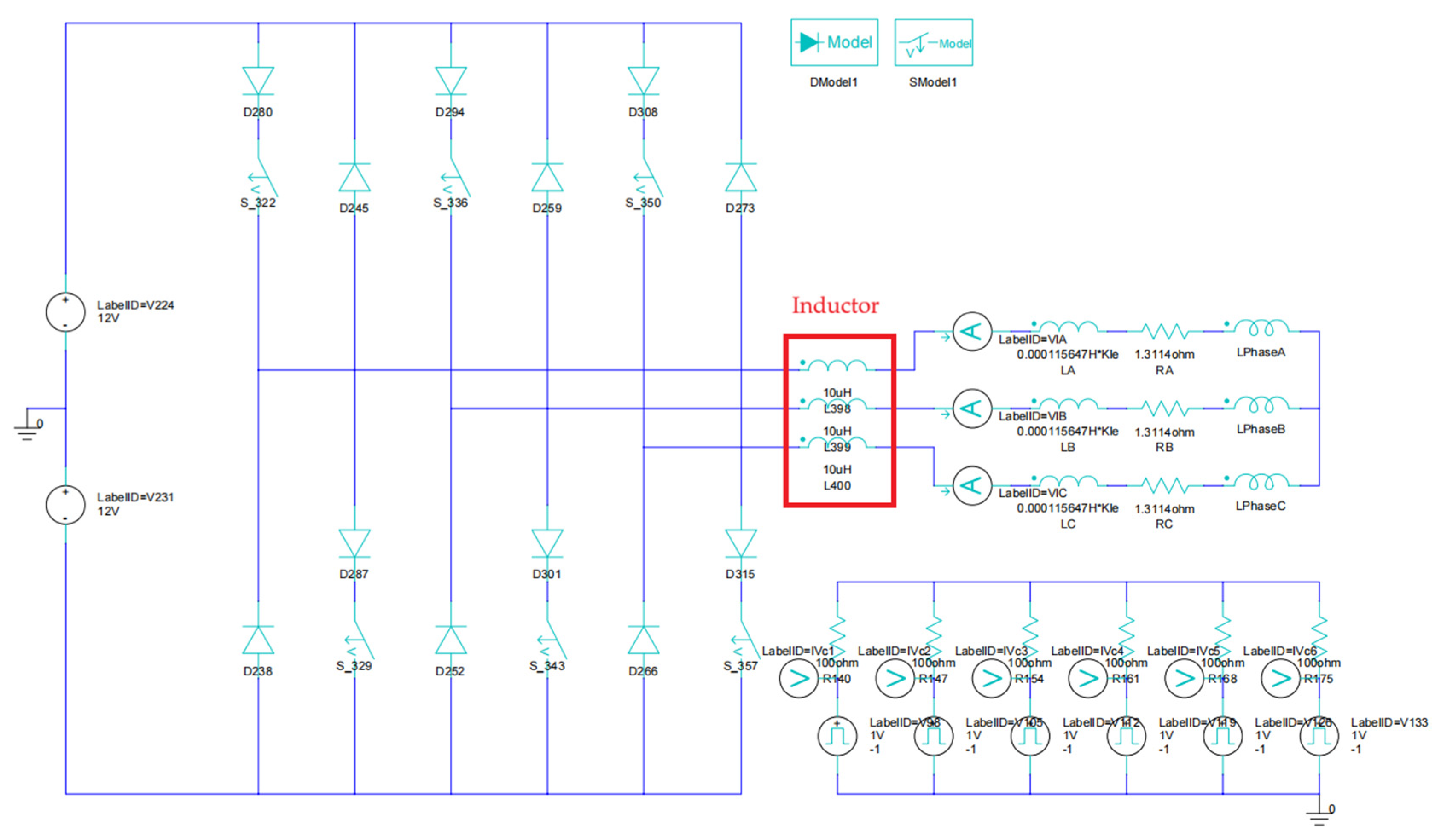
Through FE analysis, the BLDC hollow-cup motor drive circuit is established. In addition, reactors are connected in series in each three-phase circuit to analyze the core loss trend for inductance values in the range of 0 μH to 25 μH. The BLDC hollow-cup motor drive circuit is presented in Figure 2. The motor speed is 47,000 r/min, the operating frequency is 783 Hz, the power is 90 W, and the DC voltage is 24 V.

3.3. Core Loss Analysis Considering Inductance Value

The armature magneto–kinetic potential is generated by the current harmonics, which in turn generate a magnetically dense harmonic in the core, leading to an increase in core loss. Analyzed through the above equations, the armature magneto–kinetic harmonic amplitude is inversely proportional to the armature inductance L a and positively proportional to its resulting flux density amplitude B . The core loss of the BLDC hollow-cup motor is calculated based on the Bertotti core loss model [20], expressed as follows:
P Fe = K h f B 2 + K c f 2 B 2 + K e f 1.5 B 1.5 ,
where K h is the hysteresis loss factor, K c is the eddy current loss factor, K e is the additional loss factor, f is the magnetic field frequency, and B is the flux density amplitude.
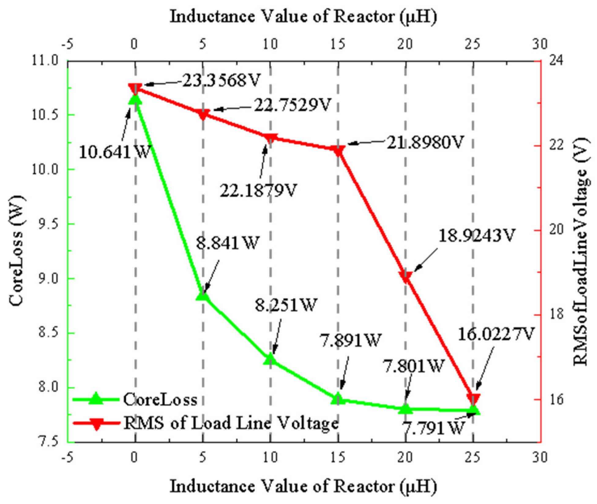
To analyze the effect of reactor inductance on the core loss, the BLDC hollow-cup motor core loss is calculated for each operating condition by increasing the reactor inductance value by 5 μH in the range of 0 μH to 25 μH. The variation of core loss with the value of the inductance of the reactor is presented in Figure 3.
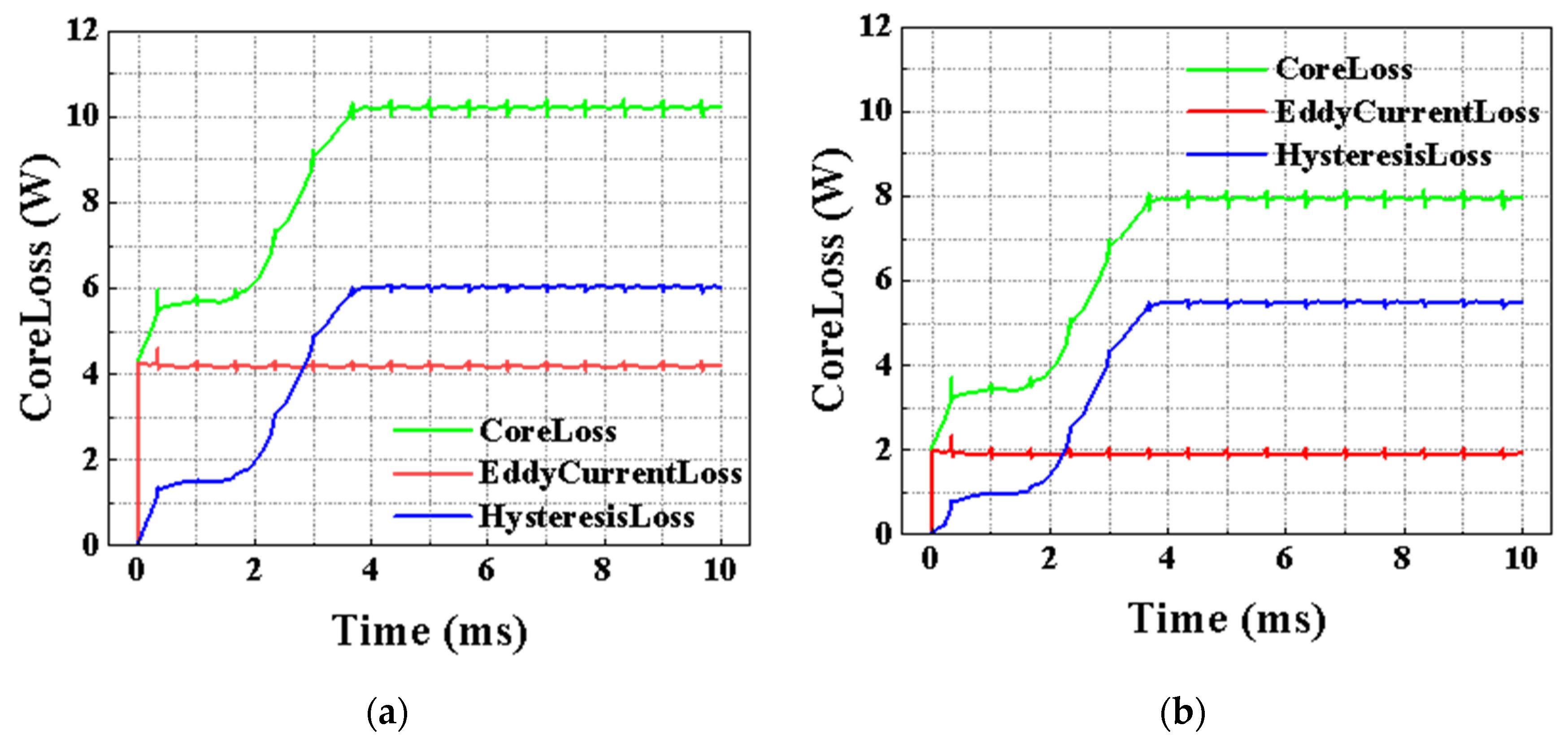
The analysis in Figure 3 shows that the core loss decreases significantly as the inductance value increases. However, as the inductance value of the reactor gradually increases, the decreasing trend of the core loss slows down. By the time the reactor inductance reaches 15 μH, the loss variation is stabilized. The variation of core loss for reactor inductance values of 0 μH and 15 μH is presented in Figure 4.

3.4. RMS of Load Line Voltage Analysis Considering Inductance Value

By the time the reactor inductance reaches 15 μH, the loss variation is stabilized. As the inductance of the controller’s voltage output continues to increase, the electrical time constant of the entire system will also increase, affecting the system’s dynamic performance. The following equations are analyzed. The reactor in series between the BLDC hollow-cup motor and the controller acts as a suppressor of the efficiency of the controller. The differential equation for the voltage at the input of the hollow-cup motor is given in Ref. [20], expressed as follows:
U a = R i a + L M d i a d t + E a ,
U b = R i b + L M d i b d t + E b ,
U c = R i c + L M d i c d t + E c ,
where U a , U b , and U c represent the three-phase voltage, E a , E b , and E c represent three opposite electromotive forces, i a , i b , and i c represent the three-phase current, R is the resistance of the three-phase circuit winding, L is the three-phase circuit inductor, and M is the mutual inductance in a three-phase circuit.
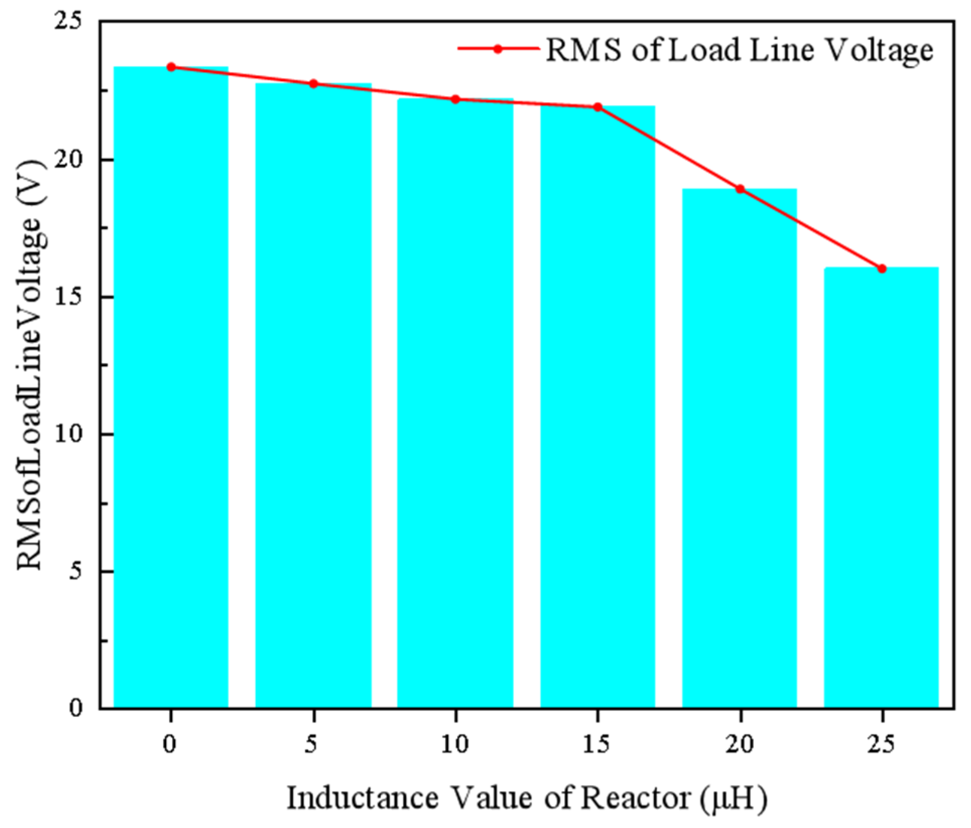
In the following steps, the calculations for the motor load line voltage are performed, the changes in value are analyzed, and the appropriate reactor value is selected. Therefore, loss suppression is achieved, while avoiding the degradation of the dynamic performance of the entire motor system due to excessive inductance values. The trend of the load line voltage RMS is analyzed for each 5 μH increase in reactor inductance in the range of 0 μH to 25 μH. The variation of line voltage RMS with the value of inductance of the reactor is presented in Figure 5.
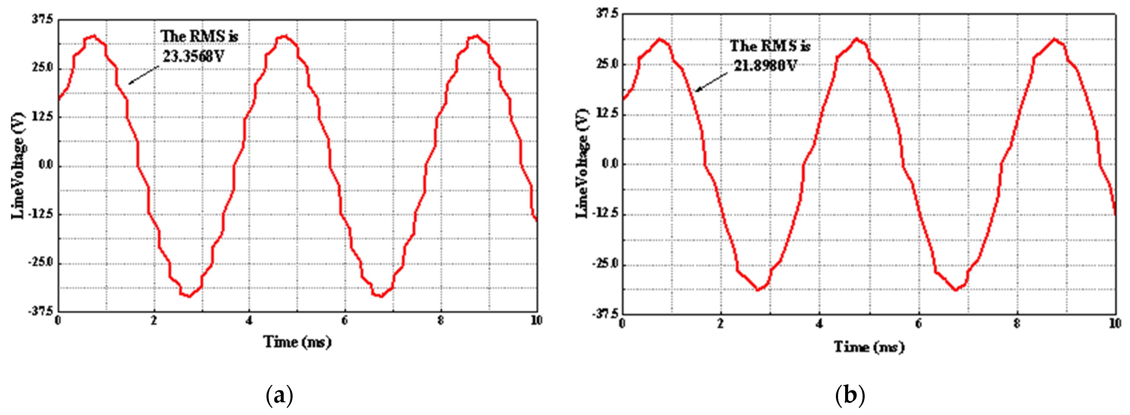
According to the FE calculation, the motor load line voltage tends to decrease with the increase in reactor inductance, and the decreasing trend is more obvious after the inductance value of 15 μH. The variation of line voltage RMS for the reactor inductance values of 0 μH and 15 μH is presented in Figure 6.
After comparative analysis, the core loss of the BLDC hollow-cup motor shows a decreasing trend with the increase in the inductance value of the reactor, and this trend tends to stabilize when the inductance value reaches 15 μH. However, the increase in inductance value will have a dampening effect on the motor load line voltage RMS. When the inductance reaches 15 μH, the motor load line voltage RMS decreases more significantly, while the output efficiency of the controller is reduced. In summary, a 15 μH reactor in series between the BLDC hollow-cup motor and the controller improves the efficiency of the motor, without affecting the voltage at the output of the controller. A comparative analysis is shown in Figure 7.
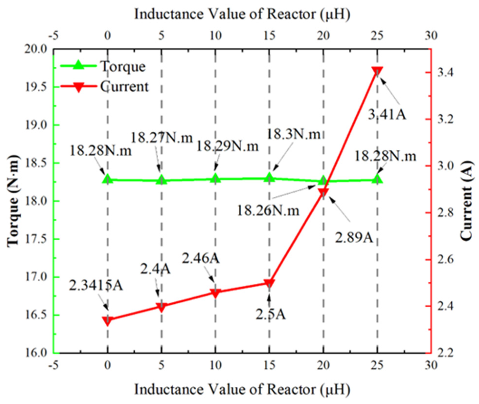
Similarly, the calculation results for current and torque also confirm this conclusion. As the effective value of the motor terminal voltage decreases (the inductance value of the reactor in the series motor system increases), to ensure that the output torque of the motor remains unchanged under rated conditions, the input current of the motor will increase accordingly. However, when the inductance value of the reactor exceeds 15 μH, the current increases from 2.5 A to around 3 A, which significantly increases the energy consumption of the motor system. The calculation results for current and torque are shown in Figure 8.

3.5. Air-Gap Density Distribution and Current Time-Harmonics Analysis

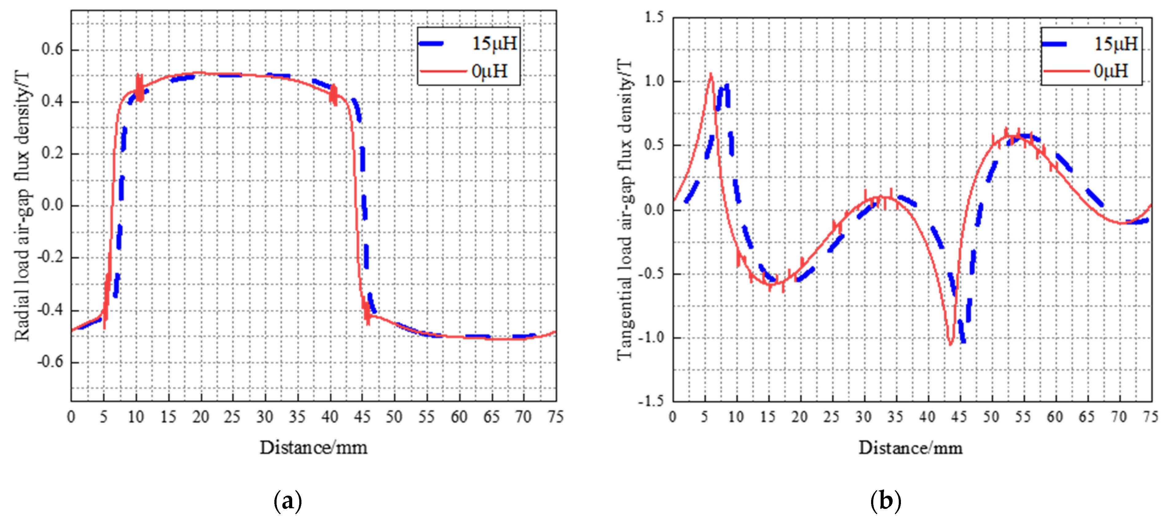
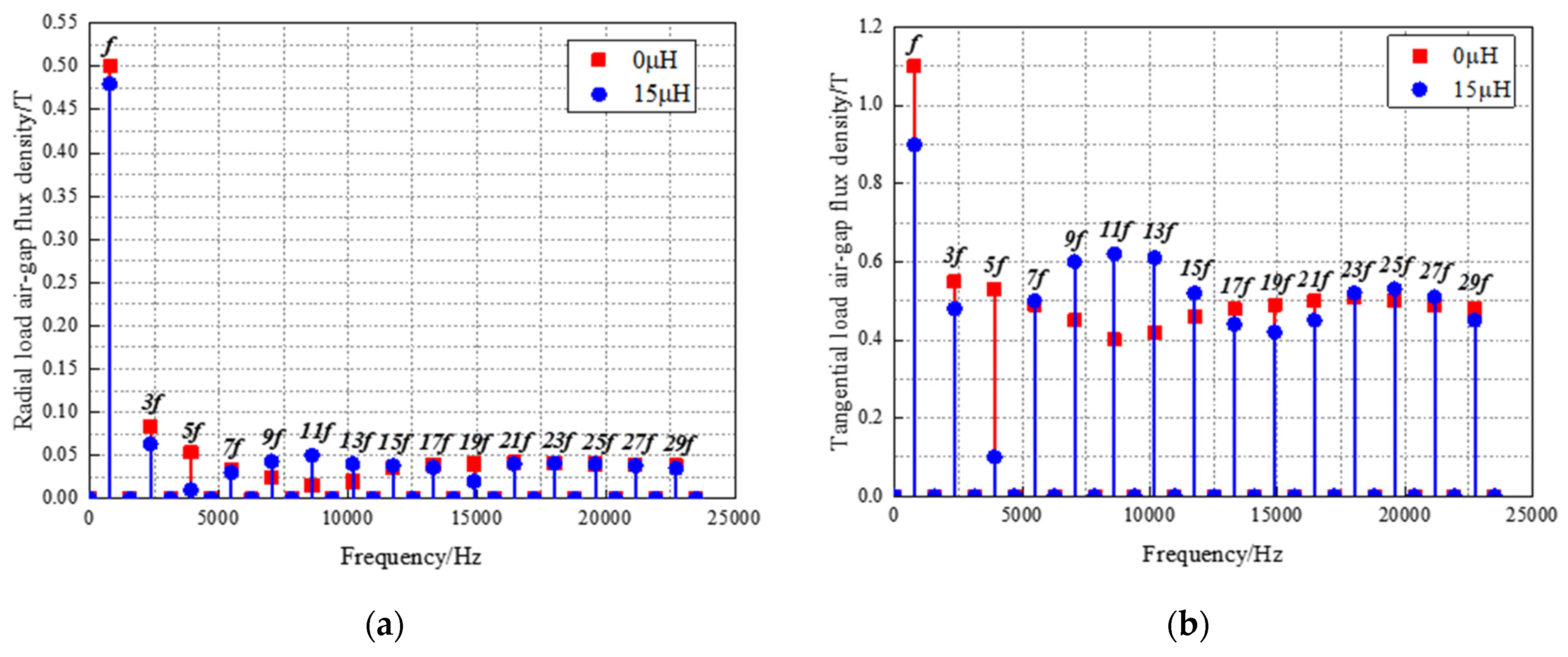
To analyze the effect of the reactor inductance value on the air-gap flux density and time harmonic, the no-load air-gap flux density and current time-harmonic spectra of the electromagnetic model, before and after the series connection of a 15 μH reactor to motor system, are comparatively analyzed. The radial and tangential air-gap flux density distributions are shown in Figure 9. The radial and tangential air-gap flux density time-harmonic amplitudes are shown in Figure 10.
The no-load air-gap flux density amplitude of the motor is approximately equal after series connection of a reactor of 15 μH. From Figure 9a, it can be observed that the optimized radial air-gap flux density curve is smoother than before optimization. Figure 9b shows that the optimized tangential air-gap flux density is reduced, and the curve is smoother.
From Figure 10a, it can be seen that harmonic of the air-gap flux density is reduced after series connection of a 15 μH reactor; the analysis of the radial air-gap flux density time-harmonic spectrum shows that the main harmonic component is the (2n − 1)th harmonic. As seen in Figure 10b, the optimization method attenuates the lower harmonics more significantly, the 3rd and 5th harmonics are attenuated more drastically, and the main harmonic component is the (2n − 1)th harmonic. From the above analysis, the air-gap flux density amplitude is reduced by series connection of a 15 μH reactor, and the current time harmonic and armature magnetomotive force harmonic are effectively suppressed.

3.6. Rotor Eddy Current Loss Analysis

The motor rotor eddy current loss is caused by the harmonic magnetic field generated by the current harmonics, while the armature potential harmonics cause an increase in rotor eddy current loss [21]. The previous Equations (1)–(8) are analyzed. It can be noticed that the amplitude of the armature potential harmonic is inversely proportional to the armature inductance and directly proportional to the flux density harmonic amplitude. Faraday’s law of electromagnetic induction is considered, and it is known that the induced electromotive force is generated in an alternating magnetic field, causing eddy currents to form on the surface of the permanent magnet. Equations for induced electromotive force and induced electromotive force magnitude are shown below [21].
E eddy = B m t l PM w PM ,
E = l PM w PM × n B n f n ,
where B m is the harmonic magnetic field, l PM is the axial length of PM, w PM is the radial length of PM, n is the number of each harmonic, B n is the harmonic magnetic density amplitude, and f n is the relative motion frequency. The PM eddy current loss equation is shown below [21].
P PM = h PM w 3 PM l 3 PM σ 2 w 2 PM + l 2 PM i s 3 / 2 I m 2 n 2 f n 2 B n 2 · V PM ,
where h PM is the radial length of PM, i s is the RMS value of the excitation current, I m is the motor input current amplitude, and V PM is the volume of PM.
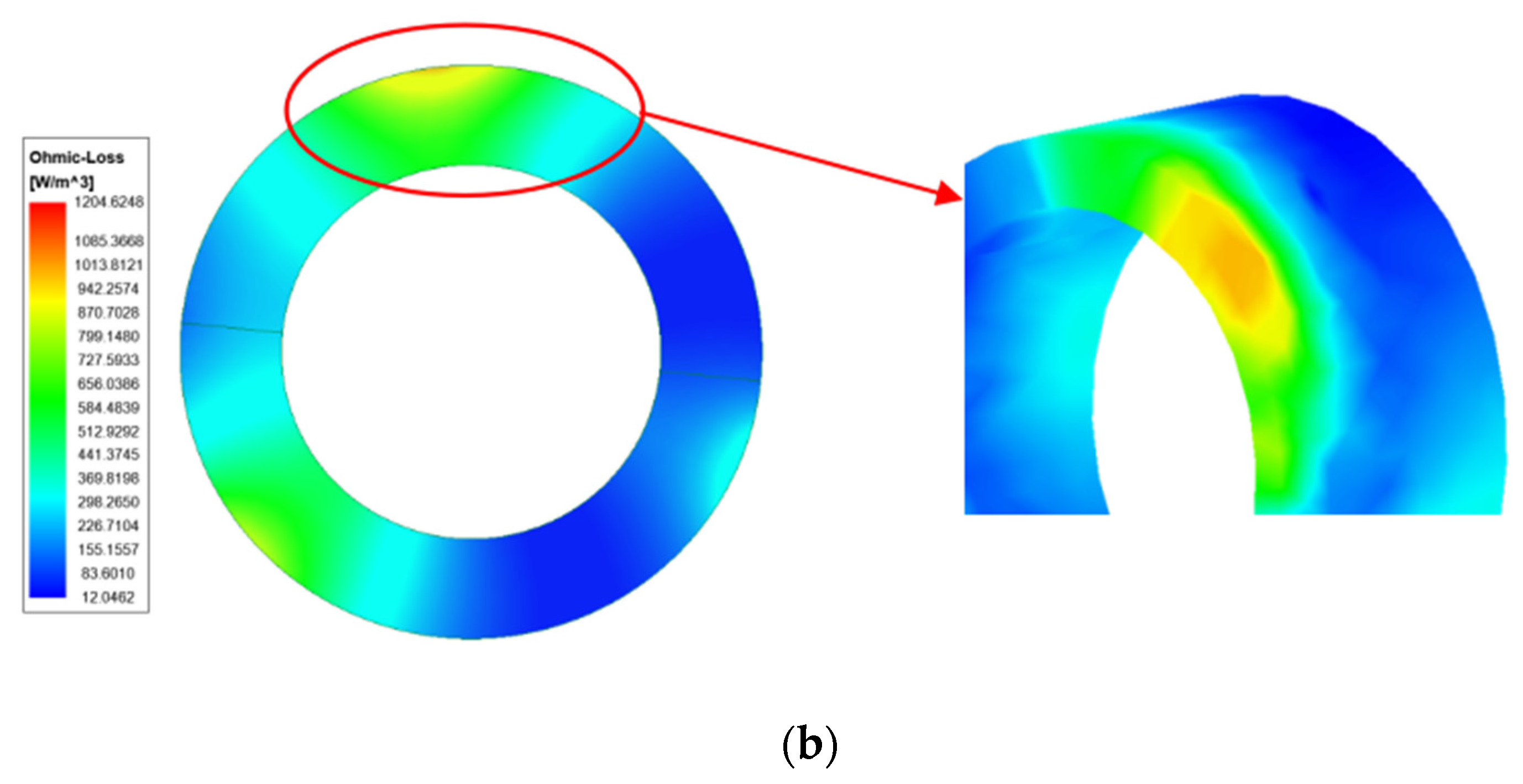
To analyze the effect of reactor inductance value on the rotor eddy current loss, the rotor eddy current loss is analyzed using the FEM when the series reactor inductance value is 0 μH and 15 μH. The rotor eddy current loss cloud diagrams for inductance values of 0 μH and 15 μH are shown in Figure 11.
Analysis of Figure 11 shows that the maximum rotor eddy current loss density is 1204.62 W/m3 when the value of reactor inductance is 0 μH, and the maximum rotor eddy current loss density is 942.26 W/m3 when the value of reactor inductance is 15 μH. The rotor eddy current loss of the BLDC hollow-cup motor is significantly reduced, by about 22% at the maximum loss density, with the series connection of a 15 μH reactor.
Through the above electromagnetic analysis, it is observed that a reactor with an inductance value of 15 μH in series between the BLDC hollow-cup motor and the controller can effectively suppress the current harmonics and the resulting armature potential harmonics. This leads to a reduction in the core loss and rotor eddy current loss generated during motor operation.

4. Electromagnetic–Temperature Field Coupling Analysis

In this section, the temperature field of a BLDC hollow-cup motor is analyzed for the following two cases:
(1)
The reactor is not connected in series between the motor and the controller.
(2)
The reactor includes the inductance of 15 μH in series between the motor and the controller.
The suppression of core losses by the reactor is verified when the motor is operated at 90 W 47,000 r/min.
The temperature field simulation steps are shown in Figure 12.

4.1. Setup Heat Source

The electromagnetic losses of the motor are calculated for different values of inductance. Electromagnetic losses for a reactor inductance of 0 μH (without a series reactor) and a reactor inductance of 15 μH are selected as the heat sources for temperature field simulation. Due to the small size of the BLDC hollow-cup motor studied in this paper, the wind friction loss is negligible. The temperature field heat sources are shown in Table 2.

4.2. Thermal Conductivity and Convection Heat Dissipation Factor

The material thermal conductivity of each component of the motor used for temperature field calculations is shown in Table 3.
The convection heat dissipation factor for the motor cooling surface is usually related to several physical quantities. To simplify the simulation calculation of the temperature field, the convection heat dissipation factor is calculated with the help of formulas and empirical constants. The convection heat dissipation factor of the inner circle of the stator and the outer circle of the rotor of the motor are affected by the rotor rotation but also by the effect of the stator inner circle surface blocking. The more common method is to use the same heat transfer coefficient for the rotor surface and the stator inner circle surface. The convection heat dissipation factor expressions [19] at the stator end face, at the rotor end face, and at the stator and rotor air gap are shown below.
α s = 1 + 0.04 v τ 0.045 ,
α r = 28 1 + 0.45 v τ ,
α δ = 28 1 + 0.5 v τ ,
where v τ is the rotor surface circumferential rotation speed, with the unit m/s. The convection heat dissipation factor for each position is calculated from the above equations, as shown in Table 4.

4.3. Temperature Field Simulation Results

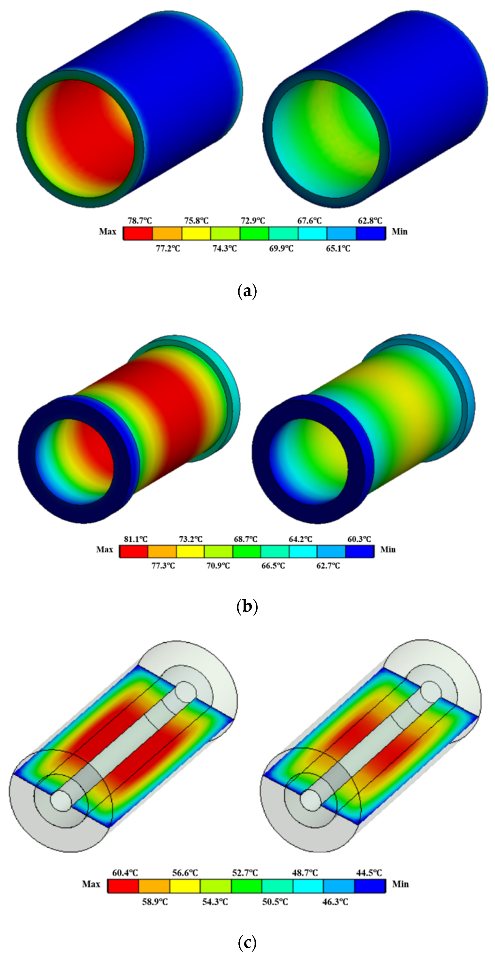
The temperature distribution of each component of the motor is calculated using temperature field simulation, as shown in Figure 13. The temperature of various parts of the motor, before and after the series connection of a 15 μH reactor, is shown in Table 5.
In summary, the maximum temperatures of the stator silicon steel, stator winding, and rotor decreased by 5.8 °C, 7.9 °C, and 6.1 °C, respectively, when the motor was operated with a 15 μH reactor in series with the controller. From the temperature field simulation results, it is shown that when the 15 μH reactor is connected in series between the motor and the controller, temperature increase is effectively reduced.

5. Experiments and Comparative Analysis

To verify the suppression effect of the reactor on the electromagnetic losses of the BLDC hollow-cup motor, based on the theoretical analysis and FE calculation in the previous section, an experimental platform is built to test the efficiency and temperature rise of the motor at the rated load.
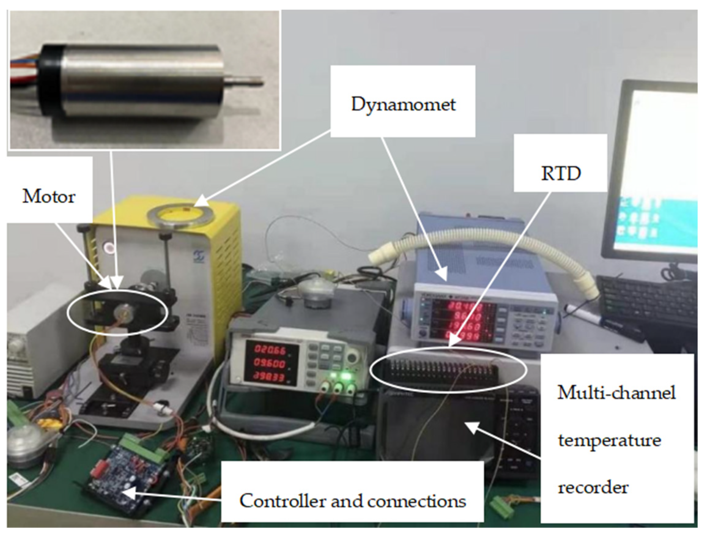
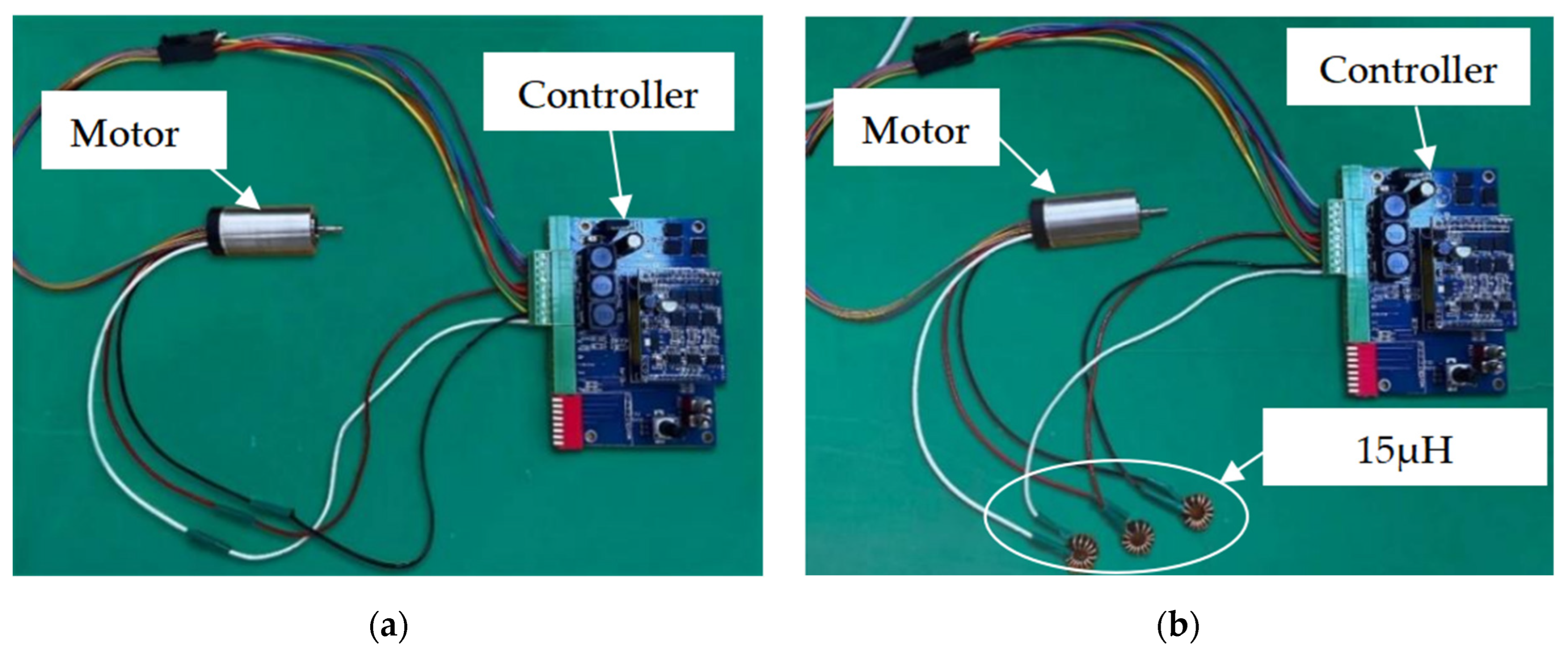
Load experiments are carried out in two cases, without a reactor in series between the motor and the controller and with a reactor of 15 μH in series, to verify the correctness and accuracy of the FE. The experimental platform with the BLDC hollow-cup motor is shown in Figure 14. The equipment includes a BLDC hollow-cup motor, reactors, a controller, a WT310 dynamometer, a PT100 sensor, and a QG6003S power supply. A comparison of the setup before and after adding the series reactor to the motor system is shown in Figure 15.

5.1. Efficiency Test Experiment

In this section, the motor efficiency is measured and calculated for the motor with no series reactor between the motor and the controller and with a 15 μH reactor in series. The results are compared and analyzed to verify the reasonableness of the optimization method.
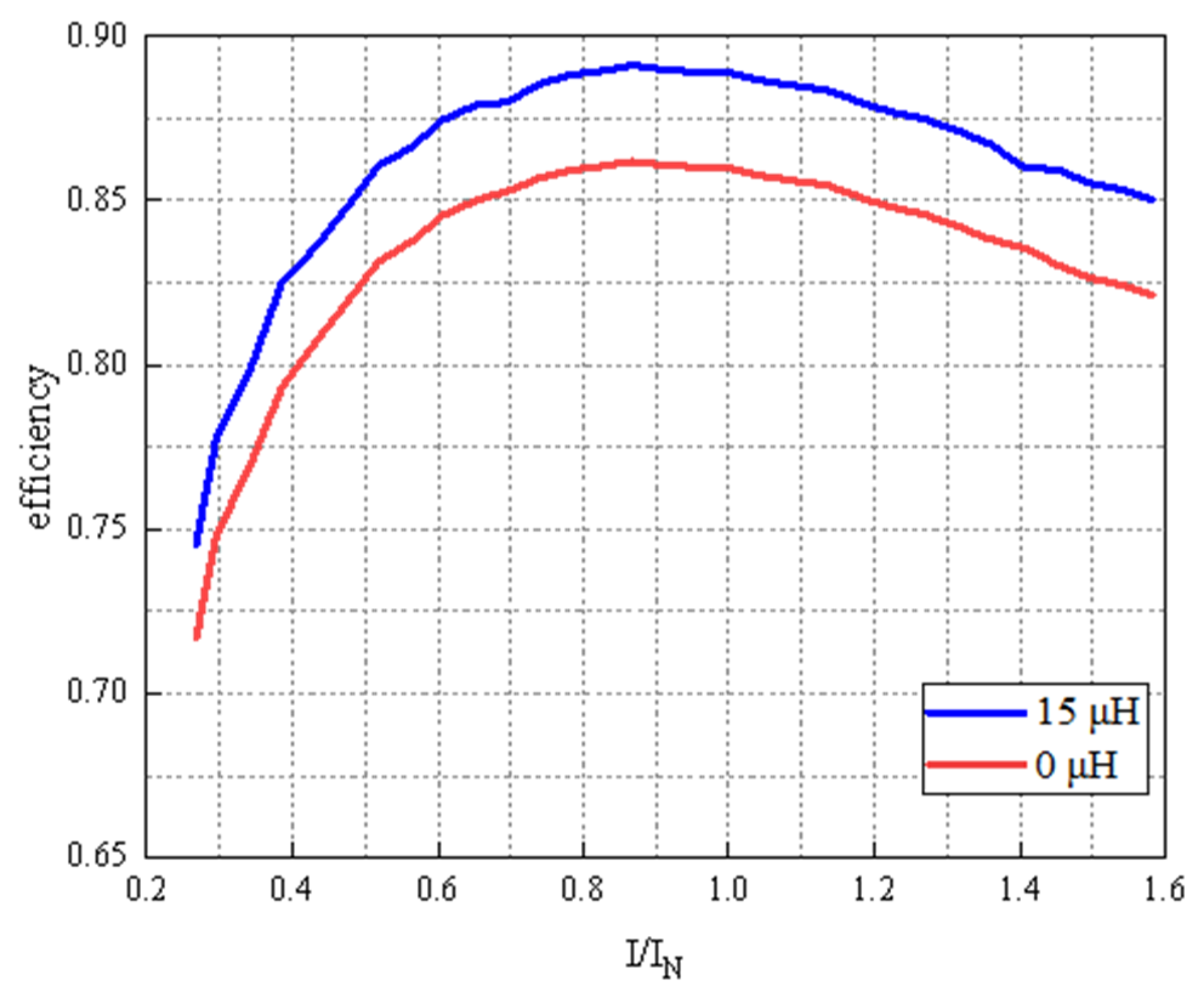
Measurements of electromagnetic torque (T), input voltage (U), and input current (I) at different rotational speeds (n) are recorded, and the efficiencies are calculated using a WT310 dynamometer. Efficiency calculations are carried out based on the MTPA (maximum torque per ampere) control method to measure the motor’s [22] success in achieving maximum torque output with minimum stator current for a given load condition. See Table A1 and Table A2 of results. The efficiency is calculated using Equation (19), and the comparison of efficiency is shown in Figure 16.
η = P 2 P 1 = T × n 9.55 / U × I .
The measured values of motor efficiency are analyzed, and under two conditions with the same input power, the motor efficiency with the 15 μH reactor in series has a significant upward trend compared to that without the reactor in series. When the input current is the rated current of the motor, the efficiency of the motor with the 15 μH reactor in series is about 3.77% higher than the efficiency of the motor without the reactor in series. This measurement shows that the motor losses are significantly reduced when the 15 μH reactor is connected in series, which is consistent with the FE simulation results.

5.2. Temperature Rise Experiment

After completing the actual measurement of the efficiency of the BLDC hollow-cup motor, the temperature rise of the winding at 15 μH in series is measured. The measured results are compared with the simulated results. The wiring of the PT100 and the motor are shown in Figure 17.
The comparison between the measured and simulated results of the winding temperature rise of the BLDC hollow-cup motor with the 15 μH reactor in series is shown in Figure 18. When the motor runs to a stable state, the winding is measured to be 74.9 °C, while the FE temperature rise calculation of the motor winding is 73.2 °C, which is a difference of 2.3%. This result shows that the difference between the simulated and measured results is within acceptable limits. It can be determined that the winding temperature is reduced by approximately 11% when the 15 μH reactor is connected in series. The above experimental results verify that the temperature rise suppression effect of series reactors on a BLDC hollow-cup motor is in accordance with the results of the previous theoretical analysis.
The reason for the deviation in the finite element calculation results from the measured results is that the temperature and humidity in the laboratory where the measurements are made are not constant. However, the initial temperature is kept constant at 25 °C in the finite element calculation, which will change the heat transfer conditions of the motor. Moreover, the mesh density during finite element calculation is not well homogenized in the complex region of the model. The above conditions cause the deviation in the theoretical compared to the measured temperature rise.

6. Conclusions

In this paper, electromagnetic loss optimization and temperature field coupling analysis are carried out for a 90 W 47,000 r/min BLDC hollow-cup motor applied in a UAV drive system. This paper focuses on the influence of different values of series reactors on motor losses and line voltage. Furthermore, the magnetic–thermal coupling simulation is adopted to compare the performance of the improved design with the original design. Finally, the simulation results are verified by the experiments of the prototype. The following conclusions were drawn.
With the increase in inductance in the BLDC hollow-cup motor system, the iron core loss is effectively reduced. However, if the inductance value exceeds a certain limit (15 µH, in this article), the RMS of the motor load line voltage can be suppressed, and the output efficiency of the motor controller can also be correspondingly suppressed.
This paper adopts an optimization method to determine which reactors will minimize the motor loss. By parameterizing the inductance value, the reactors can be investigated according to their impact on motor core losses, rotor eddy current losses, and controller efficiency. A clear reference for the research and optimization analysis of motor loss reduction is provided.
Using FEA and experimental verification, it is concluded that a reactor with an inductance value of 15 μH can increase motor efficiency by 3.77% and reduce temperature rise by 9.7%, without affecting the output voltage of the controller.

Author Contributions

Conceptualization, J.D., Y.S. and B.L; methodology, J.D., Y.S., J.Z. and B.L.; validation, J.D., J.Z. and B.L.; formal analysis, J.D., Y.S. and J.Z.; investigation, J.D., Y.S., B.L. and Y.M.; resources, J.D., J.Z. and Y.M.; data curation, J.D., Y.S., B.L. and Y.M.; writing—original draft preparation, J.D., Y.S. and B.L.; writing—review and editing, Y.S., J.Z., B.L. and Y.M.; visualization, Y.S., B.L. and Y.M.; supervision, Y.S. and Y.M.; project administration, J.D., J.Z. and Y.M.; All authors have read and agreed to the published version of the manuscript.

Funding

This work was supported in part by a sub-project of the National Key Research and Development Program of China under grant no. 2022YFC2403601.

Institutional Review Board Statement

Not applicable.

Informed Consent Statement

Not applicable.

Data Availability Statement

The data presented in this study are available upon request from the corresponding author. The data are not publicly available.

Conflicts of Interest

The authors declare no conflicts of interest.

Appendix A

Table A1. Calculated motor efficiency (no reactor is connected).
I1/InDC Current
I1/A
DC Voltage
U1/V
Input
P1/W
Speed
n/r/min
Torque
T/N·m
Output
P2/W
Effi.
ƞ/%
0.301.823.67330.8950,4890.00401221.6974.69
0.391.5923.56740.1249,8330.00638929.8979.66
0.522.1823.71253.4149,0030.00768943.5783.14
0.612.54923.48962.3348,7130.01005951.8484.67
0.703.10623.90171.8948,3980.01300859.1985.13
0.853.69823.47889.7147,2800.01499976.6786.33
0.913.74523.63393.6747,1130.01597679.4685.79
1.004.28323.678103.4546,3980.01863088.1585.67
1.094.39623.789111.0346,2890.02111394.3785.43
1.225.19923.569124.8445,0310.021986105.8984.8
1.315.71323.496132.7844,8110.024663111.4683.09
1.415.99823.465143.5944,7020.026789119.0382.99
1.506.6623.39151.7243,6950.027133124.8282.17
1.586.9123.296160.1343,3380.029386131.7481.99
Table A2. Calculated motor efficiency (15 μH reactor is connected).
I1/InDC Current
I1/A
DC Voltage
U1/V
Input
P1/W
Speed
n/r/min
Torque
T/N·m
Output
P2/W
Effi.
ƞ/%
0.301.2722.86630.3050,4070.00446323.5677.75
0.391.6622.82339.4849,9070.00623232.5782.50
0.522.2322.75952.9949,1610.00885945.6186.07
0.612.6122.71761.8848,6960.01061454.1387.47
0.703.0022.67370.9348,2280.01235962.4288.00
0.853.73522.5988.0947,3000.01584978.5189.12
0.913.9322.56892.5547,0880.01670182.3588.98
1.004.3022.527101.1246,5940.01842489.8988.90
1.094.6822.483109.9646,1240.0201597.3388.51
1.225.2622.418123.1445,3810.022727108.0187.71
1.315.6422.375131.8344,9240.024424114.9087.16
1.416.0622.327141.3344,4190.026124121.5285.98
1.506.4322.284149.7043,9590.027821128.0785.55
1.586.8022.240158.0643,5040.029504134.4185.04

References

  1. Mousavi aghdam, S.R. Design and analysis of a novel topology for slotless brushless DC (BLDC) motors with en-hanced torque and efficiency. IET Electr. Power Appl. 2021, 15, 284–298. [Google Scholar] [CrossRef]
  2. Zhang, D.; Liu, T.; Zhao, H.; Wu, T. An Analytical Iron Loss Calculation Model of Inverter-Fed Induction Motors Considering Supply and Slot Harmonics. IEEE Trans. Ind. Electron. 2019, 66, 9194–9204. [Google Scholar] [CrossRef]
  3. Zhang, J.; Cui, R.; Wei, Y.; Yu, D.; Xie, S.; Fang, S. Optimization and Experimental Validation of Amorphous Alloy High-Speed Asynchronous Motor for Simultaneous Reduction on Core and Copper Losses. IEEE Access 2023, 11, 101112–101122. [Google Scholar] [CrossRef]
  4. Yoshida, R.; Tanaka, M.; Masuda, R.; Horiuchi, M.; Takazawa, K.; Sato, M.; Mizuno, T.; Nirei, M. Reduction of Iron Loss in Ultrahigh-Speed Interior Winding Synchronous Motor Using Magnetic Composite Material. In Proceedings of the 2021 24th International Conference on Electrical Machines and Systems (ICEMS), Gyeongju, Republic of Korea, 31 October–3 November 2021. [Google Scholar]
  5. Hu, Y.; Zhu, S.; Xu, L.; Jiang, B. Reduction of Torque Ripple and Rotor Eddy Current Losses by Closed Slots Design in a High-Speed PMSM for EHA Applications. IEEE Trans. Magn. 2021, 58, 8102206. [Google Scholar] [CrossRef]
  6. Ishikawa, T.; Takahashi, K.; Ho, Q.V.; Matsunami, M.; Kurita, N. Analysis of Novel Brushless DC Motors Made of Soft Magnetic Composite Core. IEEE Trans. Magn. 2012, 48, 971–974. [Google Scholar] [CrossRef]
  7. Soda, N.; Hayashi, N.; Enokizono, M. Analytical Study on Core Loss Reduction of Segmented Stator Core Motor in Con-sideration of Rolling Direction of Nonoriented Electrical Steel Sheet. IEEE Trans. Ind. Appl. 2021, 57, 4745–4753. [Google Scholar] [CrossRef]
  8. Yamazaki, K.; Utsunomiya, K.; Tanaka, A.; Nakada, T. Rotor Surface Optimization of Interior Permanent Magnet Synchronous Motors to Reduce Both Rotor Core Loss and Torque Ripples. IEEE Trans. Ind. Appl. 2022, 58, 4488–4497. [Google Scholar] [CrossRef]
  9. Ma, J.; Zhu, Z.Q. Magnet Eddy Current Loss Reduction in Permanent Magnet Machines. IEEE Trans. Ind. Appl. 2019, 55, 1309–1320. [Google Scholar] [CrossRef]
  10. Zhang, Z.; Deng, Z.; Gu, C.; Sun, Q.; Peng, C.; Pang, G. Reduction of Rotor Harmonic Eddy-Current Loss of High-Speed PM BLDC Motors by Using a Split-Phase Winding Method. IEEE Trans. Energy Convers. 2019, 34, 1593–1602. [Google Scholar] [CrossRef]
  11. Liang, Y.; Zhao, F.; Xu, K.; Wang, W.; Liu, J.; Yang, P. Analysis of Copper Loss of Permanent Magnet Synchronous Motor With Formed Transposition Winding. IEEE Access 2021, 9, 101105–101114. [Google Scholar] [CrossRef]
  12. Niu, L.; Zhang, M. The Loss and Efficiency Analysis and Research of Interior Permanent Magnet Synchronous Motors for Traction Applications. IEEE Access 2023, 11, 5538–5557. [Google Scholar] [CrossRef]
  13. Bhattacharya, K.; Santra, S.B.; Chatterjee, D.; Padmanaban, S. Torque Ripple and Loss Minimization of Trapezoidal Brushless DC Motor Drive by Harmonics Current Excitation Switching Technique. In Proceedings of the 2020 IEEE International Conference on Power Electronics, Smart Grid and Renewable Energy (PESGRE), Cochin, India, 2–4 January 2020; pp. 1–6. [Google Scholar]
  14. Minh, D.B.; Quoc, V.D.; Huy, P.N. Efficiency Improvement of Permanent Magnet BLDC Motors for Electric Vehicles. Engi-Neering. Technol. Appl. Sci. Res. 2021, 11, 7615–7618. [Google Scholar] [CrossRef]
  15. Im, S.H.; Gu, B.G. Interturn fault tolerant drive method by limiting copper loss of interior permanent magnet synchronous motor. IEEE Trans. Ind. Electron. 2019, 67, 7973–7981. [Google Scholar] [CrossRef]
  16. Vafaie, M.H.; Mirzaeian Dehkordi, B. Minimising power losses and torque ripples of permanent-magnet synchronous motor by parallel execution of a two-stage predictive control system. IET Power Electron. 2020, 13, 3590–3600. [Google Scholar] [CrossRef]
  17. Karnavar, P.H.; Jisha, V. Harmonic Reduction and Power Factor Improvement of BLDC Motor Drive System Using a Selective Harmonic Elimination PWM Based Controller. In Proceedings of the 2020 International Conference on Power, Instrumentation, Control and Computing (PICC), Thrissur, India, 17–19 December 2020; pp. 1–5. [Google Scholar]
  18. Khazaee, A.; Zarchi, H.A.; Markadeh, G.A. Loss model based efficiency optimized control of brushless DC motor drive. ISA Trans. 2018, 86, 238–248. [Google Scholar] [CrossRef] [PubMed]
  19. Yu, Y.; Chai, F.; Pei, Y.; Doppelbauer, M. Investigation of PM Loss in Spoke-Type Permanent Magnet Vernier Motors With Different Stator Topologies for In-Wheel Direct Drive. IEEE Trans. Ind. Appl. 2022, 58, 4562–4574. [Google Scholar] [CrossRef]
  20. Liu, K.; Chen, J.; Wang, Y.; Qiu, S.; Lin, J.; Zhang, C. Temperature Analysis of the Surface-mounted Permanent Magnet Synchronous Motor. In Proceedings of the 2023 IEEE 18th Conference on Industrial Electronics and Applications (ICIEA), Ningbo, China, 18–22 August 2023; pp. 315–319. [Google Scholar]
  21. Li, Z.; Wang, P.; Liu, L.; Xu, Q.; Che, S.; Zhang, L.; Du, S.; Zhang, H.; Sun, H. Loss calculation and thermal analysis of ultra-high speed permanent magnet motor. Heliyon 2022, 8, e11350. [Google Scholar] [CrossRef] [PubMed]
  22. Ou, J.; Liu, Y.; Liang, D.; Doppelbauer, M. Investigation of PM Eddy Current Losses in Surface-Mounted PM Motors Caused by PWM. IEEE Trans. Power Electron. 2019, 34, 11253–11263. [Google Scholar] [CrossRef]
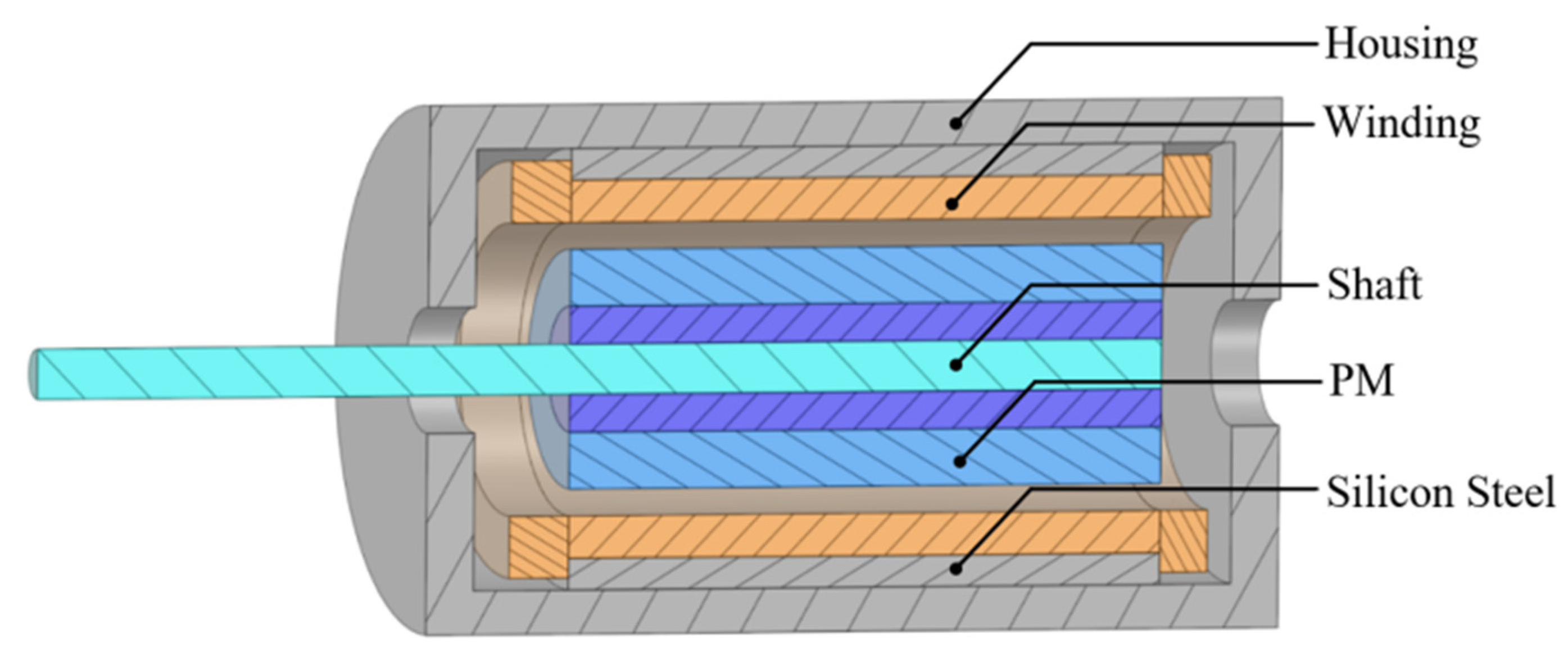
Figure 1. A 3D Model of the BLDC hollow-cup motor.
Applsci 15 01523 g001
Figure 2. BLDC hollow-cup motor drive circuit.
Applsci 15 01523 g002
Figure 3. Variation of core loss with inductance of reactor.
Applsci 15 01523 g003
Figure 4. Variation of core loss at different values of inductance: (a) core loss at inductance of 0 μH; (b) core loss at inductance of 15 μH.
Applsci 15 01523 g004
Figure 5. Variation of line voltage RMS with inductance of reactor.
Applsci 15 01523 g005
Figure 6. Variation of line voltage RMS at different values of inductance: (a) line voltage RMS at value of 0 μH; (b) line voltage RMS at value of 15 μH.
Applsci 15 01523 g006
Figure 7. Comparative analysis.
Applsci 15 01523 g007
Figure 8. Results for current and torque.
Applsci 15 01523 g008
Figure 9. Air-gap flux density before and after series connection of 15 μH reactor: (a) radial air-gap flux density; (b) tangential air-gap flux density.
Applsci 15 01523 g009
Figure 10. Air-gap flux density time-harmonic amplitude before and after series connection of 15 μH reactor: (a) radial air-gap flux density time-harmonic amplitude; (b) tangential air-gap flux density time harmonic amplitude.
Applsci 15 01523 g010
Figure 11. Rotor eddy current loss at different values of inductance: (a) rotor eddy current loss at inductance value of 0 μH; (b) rotor eddy current loss at inductance value of 15 μH.
Applsci 15 01523 g011aApplsci 15 01523 g011b
Figure 12. Temperature field simulation steps.
Applsci 15 01523 g012
Figure 13. Temperature distribution of each component before and after series connection of a reactor with an inductance value of 15 μH: (a) stator (silicon steel) before and after series connection of 15 μH reactor; (b) stator (winding)before and after series connection of 15 μH reactor; (c) rotor before and after series connection of 15 μH reactor.
Applsci 15 01523 g013
Figure 14. The experimental platform.
Applsci 15 01523 g014
Figure 15. Comparison of the setup before and after adding a series reactor to the motor system: (a) before adding the system series reactor; (b) after adding the system series reactor.
Applsci 15 01523 g015
Figure 16. Comparison of efficiency.
Applsci 15 01523 g016
Figure 17. Wiring of PT100 and motor.
Applsci 15 01523 g017
Figure 18. Comparison between measured and simulated results.
Applsci 15 01523 g018
Table 1. Parameters of the motor.
Motor ParametersNumerical Value
Rated power90 W
Rated voltage (DCV)24 V
Rated speed47,000 r/min
Rated efficiency85%
Frequency783 Hz
Number of poles2
Air-gap length0.5 mm
Stator inner diameter20 mm
Stator outer diameter27 mm
Stator length50 mm
PM length50 mm
Table 2. Temperature field heat source.
Inductance
of Reactor/μH
Core Loss
/W
Winding Loss
/W
Rotor Eddy
Current Loss/W
0 (without reactor)10.648.641.49
158.034.990.98
Table 3. Thermal conductivity of each component material.
Component
(Material)
Density
/(kg/m3)
Constant-Pressure Specific Heat Capacity/(j/(kg.k))Thermal Conductivity
/(W/(m.k))
Stator (Silicon Steel)765050240
Winding (Copper)8987381387.6
Winding (Copper)840050412
Table 4. Convection heat dissipation factor of component.
ComponentConvection Heat Dissipation Factor/(W/(m2·°C))
Stator end face44.1
Rotor end face121.2
Rotor surface and stator
inner circle
126.2
Table 5. The temperature of each component.
Component
(Material)
Tmax/°C
(Reactor Inductance = 0)
Tmax/°C
(Reactor Inductance = 15 µH)
Temperature
Difference/°C
Stator (Silicon Steel)78.772.9−5.8
Winding (Copper)81.173.2−7.9
Rotor60.454.3−6.1
Disclaimer/Publisher’s Note: The statements, opinions and data contained in all publications are solely those of the individual author(s) and contributor(s) and not of MDPI and/or the editor(s). MDPI and/or the editor(s) disclaim responsibility for any injury to people or property resulting from any ideas, methods, instructions or products referred to in the content.