Article

Induction Motor Dynamics Regimes: A Comprehensive Study of Mathematical Models and Validation

Institute of Solid State Physics, University of Latvia, 8 Kengaraga, LV-1063 Riga, Latvia
Appl. Sci. 2025, 15(3), 1527; https://doi.org/10.3390/app15031527 (registering DOI)
Submission received: 14 January 2025 / Revised: 29 January 2025 / Accepted: 30 January 2025 / Published: 2 February 2025

Abstract

:
This study investigates the dynamic behavior of induction motors (IMs) by developing and validating four distinct mathematical models designed for transient and starting regimes. These models, expressed in α,β and d,q coordinate systems, analyze rotational frequency, electromagnetic torque, and current profiles with varying levels of complexity, including current-based, flux linkage-based, and rotor winding electromagnetic time constant approaches. Implemented in Fortran, the models address the limitations of predefined tools like MATLAB/Simulink, offering enhanced precision, flexibility, and suitability for non-standard scenarios. Validation against experimental data from a 3 kW induction motor confirms the models’ accuracy, with consistent results across approaches. Notably, the flux linkage models excel in capturing intricate transient phenomena, while current-based models simplify integration with power system studies. These findings provide a robust framework for analyzing IM performance under diverse conditions such as voltage unbalance and rundown scenarios, enabling the optimization of motor operations in energy-intensive industries.

1. Introduction

Induction motors with squirrel-cage rotors (IMs) are the most widely used type of electric motor [1]. They are relatively inexpensive and require minimal maintenance [2]. IMs are extensively utilized across various applications, including metalworking, woodworking, and general purpose machinery. They are also employed in press-forming, weaving, sewing, hoisting, and earth-moving equipment, as well as in fans, pumps, compressors, centrifuges, escalators, electric hand tools, household appliances, and numerous other devices [3,4,5,6,7]. Additionally, induction motors are commonly used in hydrogen compression systems due to their reliability, efficiency, and ease of maintenance [8,9,10]. It is difficult to identify any industry that does not rely on induction motors [11,12].
According to statistical data, electric motors and motor systems in industrial and infrastructure applications with pumps, fans, and compressors in buildings are responsible for 53% of the world’s total electricity consumption [13] (Figure 1). This underscores the significant role of IMs as the most widely used type of electric machine in the industrial sector.
The theory of transient processes in electrical machines has been extensively developed, as demonstrated by numerous studies on this topic [14,15,16,17,18,19].
With the increase in machine capacities and their intensified usage, there has been a growing demand for higher precision in modeling complex processes in induction motors [20,21]. This has necessitated the refinement and development of motor calculation methods. However, achieving both high precision and simplicity in the solutions simultaneously remains a persistent challenge [22].
Transient processes in induction motors (IM) are so diverse that it is impossible to study them comprehensively. As a result, research in this field is ongoing, as evidenced by a wide range of topics published in various sources. These studies primarily focus on the following aspects of IM operation: the starting regime [23,24], switching mode [25,26,27], operation under voltage unbalance [28,29,30,31], diagnostics [32,33,34,35], and IM parameter identification [36,37,38,39,40,41,42]. Transient analysis is essential for accurately predicting dynamic behaviors such as starting currents, electromagnetic torque, and speed profiles in induction motors. This understanding enables the design of appropriate protection systems, optimized switching devices, and configurations that enhance motor and network performance. By addressing challenges such as voltage unbalance and load variations, transient analysis ensures both motor efficiency and reliable operation of power systems.
Inrush currents arising in the stator and rotor windings during the starting process follow a complex oscillatory pattern [22]. The electromagnetic torque induced by these currents also exhibits oscillatory behavior and is a complex function of time [43]. Calculating the starting currents and torques of induction motors is essential for selecting appropriate protection and switching devices. Furthermore, it is crucial for assessing the permissible voltage drop in the network during motor starting, especially when the motor’s capacity is comparable to that of the power supply equipment [44,45].
Transient processes do not last long. However, their effect on electric machine operation and the overall network and drive system can be significant [18]. Transient processes are more diverse and complicated than steady-state processes, which are generally transient processes particular case. Transient processes appear in electric machines when voltage, frequency, or load changes occur, such as switching machine on or off, reversing, short circuit, or parameter changes [46,47,48]. These processes are influenced by various factors, and their combinations can vary widely (e.g., voltage changes, frequency, equivalent parameters, or load variations). Therefore, it is essential to identify the primary influencing factors and avoid making the task overly complicated [49,50,51,52].
For induction motor transient processes research and analysis, mathematical modeling methods are widely applied [53,54,55,56]. The growing demand for precision in modeling induction motor dynamics has driven advancements in computational tools. MATLAB/Simulink, with its user-friendly interface and extensive library, is widely used for real-time modeling of dynamic regimes in induction motors [57,58,59,60,61]. However, Simulink has notable disadvantages, particularly in specific applications. For instance, predefined macromodules often lack transparency regarding their internal structure, which limits their adaptability for non-standard scenarios or fault conditions [62,63]. Additionally, while Simulink blocks offer ease of use through drag-and-drop functionality, their predefined functionality and options can be restrictive. Users may struggle to find blocks that suit specific needs, or they may face challenges in adjusting the behavior or appearance of existing blocks. Compatibility issues between different versions or plat-forms of Simulink can further complicate its application [62,64].
Another significant limitation of Simulink, particularly in the context of power systems and power electronics, is its computational speed. For large-scale systems, the state-space solver used by Simulink can become considerably slower than traditional solvers, such as the nodal admittance methods employed in tools like EMTP-RV and PSCAD. This drawback is especially critical in real-time applications, where low and consistent simulation time steps are essential [65].
In contrast, custom modeling approaches, such as those developed in Fortran, overcome these limitations by offering greater precision, reliability, and flexibility, particularly in scenarios requiring detailed customization [66]. Fortran’s strengths enable the efficient simulation of various operating modes, including power asymmetry and transient processes, making it a robust platform for advancing the study of induction motor dynamics beyond the constraints of predefined tools. Moreover, its adaptability allows it to serve as a verification tool for validating the functionality of predefined tools like Simulink.
This study aims to address these challenges by developing mathematical models tailored for analyzing the dynamic regimes of induction motors (IMs), which are crucial in numerous industrial applications. By leveraging four distinct modeling approaches, it provides a comprehensive framework for simulating key parameters such as rotational frequency, electromagnetic torque, and current profiles under diverse operating conditions. This approach enhances the understanding of transient processes in IMs and lays the foundation for optimizing their performance, particularly in energy-intensive industries.

2. Transient Process Modeling in Induction Motor

2.1. Coordinate Conversion

To simplify the mathematical description of an induction motor (IM), coordinate system transformations and the space vector concept are often employed [67]. The goal of such transformations is to obtain equations with constant coefficients, making analysis and control easer.
This simplification is achieved using the two-axis theory, which considers not the actual magnetic flux in the air gap but its components along two mutually perpendicular axes—longitudinal and transverse (d-axis and q-axis) [68]. Coordinate transformations are widely used in technical applications to simplify complex systems by converting coordinates from one system to another. This process is known as coordinate conversion.
According to mathematical principles, the number of variables remains unchanged after a coordinate transformation. Typically, a system of equations with time-varying coefficients (e.g., in the ABC phase coordinate system) is transformed into a system with constant coefficients in the dq0 coordinate system.
In general, the transformation involves converting an equation system with varying coefficients in the phase coordinate system (A, B, C or 1A, 1B, 1C) into an equivalent system expressed in the dq0 coordinate system. This transformation simplifies the mathematical representation and facilitates the analysis and control of electrical machines [69].
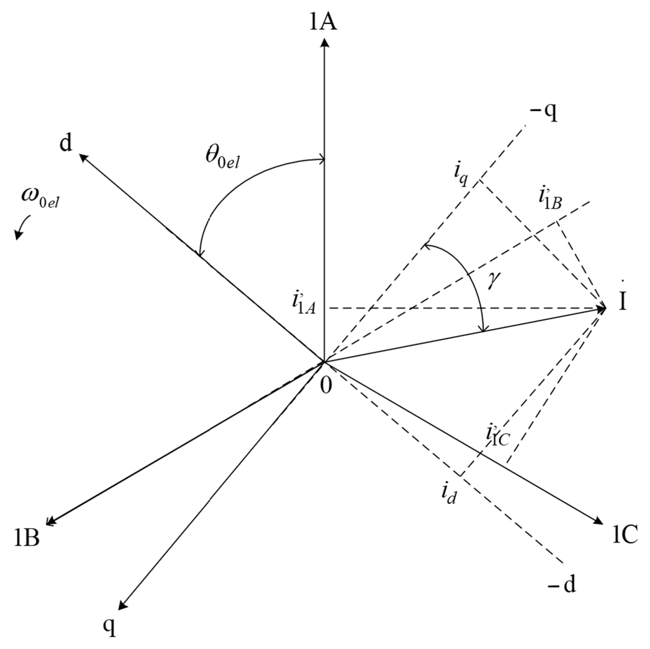
An example of such a transformation is the conversion of the stator current space vector I ˙ from the phase coordinates (1A, 1B, 1C) into the dq0 coordinate system (Figure 2).
If the phase currents contain a zero-sequence component, such that we define the zero-sequence component as: i 1 A + i 1 B + i 1 C / 3 = i 0 .
This zero-sequence current i 0 may vary according to any complex principle and should not be confused with the alternating zero-sequence space vector current I ˙ .
The concept of zero-sequence current is introduced as part of the coordinate transformation methodology to provide a complete theoretical framework. However, in the context of the four models developed and analyzed in this study, zero-sequence current is not present due to the assumption of a balanced three-phase system. Under balanced conditions, the sum of the phase currents is zero, and no zero-sequence current flows. This assumption simplifies the analysis and allows the focus to remain on the primary components of transient and starting dynamics.
The coordinate axis 0 is perpendicular to the plane of the figure. In this case, the space vector I ˙ in the ABC coordinate system can be expressed as follows: i 1 A = i 1 A i 0 , i 1 B = i 1 B i 0 , i 1 C = i 1 C i 0 , such that i 1 A + i 1 B + i 1 C = 0 .
Transforming the vector projections onto the phase axes provides the phase winding currents i 1 A , i 1 B ,   i 1 C , while projections onto the rotor axes yield the currents i d and i q . In the general case, when the stator windings are connected in wye with a neutral wire, it is possible for i 1 A + i 1 B + i 1 C 0 . In this situation, we account for the zero-sequence component as: i 1 A + i 1 B + i 1 C / 3 = i 0 , where i 0 is the stator current’s zero-sequence component.
i 1 A = i 1 A + i 0
i 1 B = i 1 B + i 0
i 1 C = i 1 C + i 0 .
It should be noted that the currents marked with “prime” (e.g., i 1 A ) no longer contain the zero-sequence component. Therefore, the currents i 1 A = i 1 A i 0 , i 1 B = i 1 B i 0 , i 1 C = i 1 C i 0 can be represented as the projections of I ˙ onto the 1A, 1B, 1C ensuring that i 1 A + i 1 B + i 1 C = 0 , as shown in Figure 2.
The relationship between the space vector components and the phase currents can be expressed as follows:
i 1 A + i 1 B + i 1 C = 0
i 1 B = I cos γ + π 2 θ 0 e l + 2 π 3 = I sin γ θ 0 e l + 2 π 3 ,
i 1 C = I cos γ + π 2 θ 0 e l 2 π 3 = I sin γ θ 0 e l 2 π 3
In the longitudinal axis d, and transverse axis q, the currents are given as:
i d = I cos γ + π 2 = I sin γ ,
i d = I cos γ + π 2 = I sin γ .
Substituting Equations (4)–(6) in Equations (1)–(3) and using (7) and (8), the phase current can be expressed as:
i 1 A = I sin γ cos θ 0 e l + I cos γ sin θ 0 e l + i 0 = i d cos θ 0 e l i q sin θ 0 e l + i 0
i 1 B = I sin γ cos θ 0 e l 2 π 3 + I cos γ sin θ 0 e l 2 π 3 + i 0 = i d cos θ 0 e l 2 π 3 i q sin θ 0 e l 2 π 3 + i 0 ;
i 1 C = I sin γ cos θ 0 e l + 2 π 3 + I cos γ sin θ 0 e l + 2 π 3 + i 0 = i d cos θ 0 e l + 2 π 3 i q sin θ 0 e l + 2 π 3 + i 0 .
Equations (9)–(11) can be written in matrix form as:
i 1 A i 1 B i 1 C = cos θ 0 e l sin θ 0 e l 1 cos θ 0 e l 2 π 3 sin θ 0 e l 2 π 3 1 cos θ 0 e l + 2 π 3 sin θ 0 e l + 2 π 3 1 .
Here, the transformation matrix is:
[ A 1 1 ] = cos θ 0 e l sin θ 0 e l 1 cos θ 0 e l 2 π 3 sin θ 0 e l 2 π 3 1 cos θ 0 e l + 2 π 3 sin θ 0 e l + 2 π 3 1
The Park transformation matrix A 1 , is given as:
[ A 1 ] = 2 3 cos θ 0 e l cos θ 0 e l 2 π 3 cos θ 0 e l + 2 π 3 sin θ 0 e l sin θ 0 e l 2 π 3 sin θ 0 e l + 2 π 3 1 2 1 2 1 2
Using this matrix, phase currents i 1 A , i 1 B , i 1 C can be transformed into d, q, 0 coordinates:
i d = 2 3 i 1 A cos θ 0 e l + i 1 B cos θ 0 e l 2 π 3 + i 1 C cos θ 0 e l + 2 π 3 ,
i q = 2 3 i 1 A sin θ 0 e l i 1 B sin θ 0 e l 2 π 3 i 1 C cos θ 0 e l + 2 π 3
i 0 = 1 3 i 1 A + i 1 B + i 1 C .
Formula (17) corresponds to i 0 expression, which was received in the beginning of chapter. Equations (15)–(17) we can obtain directly, projecting phase currents i 1 A , i 1 B , i 1 C on the coordinate axes d,q. Then, received expressions should be multiplied to two out of three.
The matrices A 1 1 and A 1 establish the relationship between the actual stator winding currents and the transformed variables in the d, q, and 0 axes. Similarly, analogous expressions can be derived for voltages:
u d u q u 0 = A 1 u 1 A u 1 B u 1 C
The same transformation applies to the electromotive forces (EMFs) and flux linkages in the stator windings:
ψ d ψ q ψ 0 = A 1 ψ 1 A ψ 1 B ψ 1 C .

2.2. Generalized Electric Machine

The theory of electric machines traditionally examines different types of electromechanical transformations separately. This approach stems from historical developments in the field, where scientists in electromechanics established distinct theories for various machine types [70,71]. While these theories emphasize the unique features of each machine, they also highlight significant similarities in design principles and calculation methods [72].
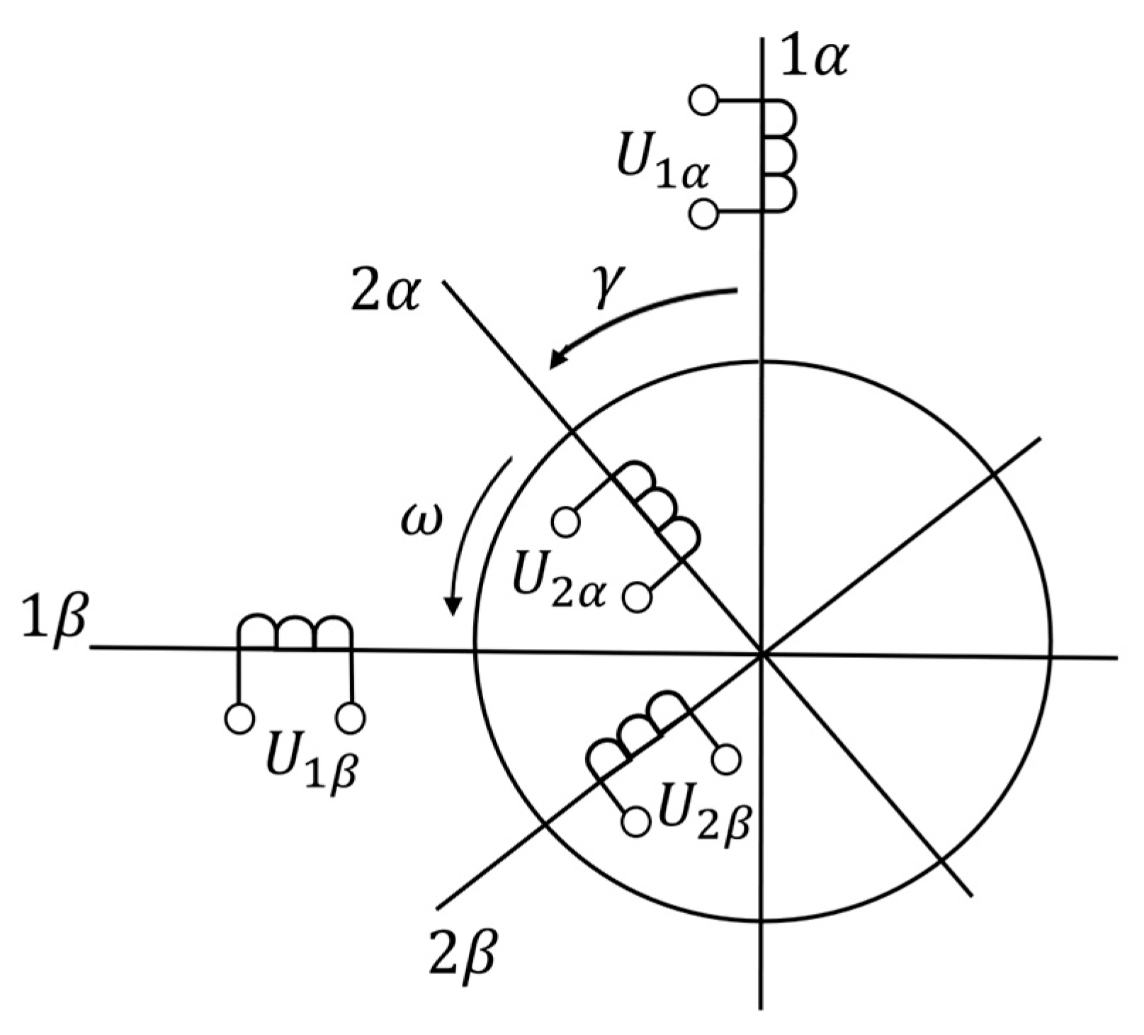
One key similarity is the presence of a sinusoidal magnetic field in the motor air gap. To develop a generalized theory of electric machines, we consider an idealized two-pole, two-phase symmetrical electric machine. This idealized machine features mutually perpendicular windings on both the rotor and stator, as illustrated in Figure 3 [67].
A two-pole machine was selected because the processes in two-pole and multi-pole machines are analogous. In a two-pole machine, electrical radians align with geometric radians, simplifying the comparison of the rotor position relative to the stator phases, especially during transient processes. In a two-phase machine, spatially displacing the windings by π/2 generates a circular magnetic field. This configuration combined with a uniform air gap eliminates mutual inductive coupling between windings and simplifies the machine equations. For this reason, three-phase machines are frequently converted into two-phase machines for analytical purposes [73,74].
The generalized electric machine assumes a uniform air gap, with no slots on the stator or rotor. They are modeled as current layers with a sinusoidal magnetomotive force distribution. Feeding the windings with alternating current produces a sinusoidal magnetic field in the air gap, given the uniform magnetic circuit and the absence of saturation. This generalized model represents a pair of intermoving windings and serves as a mathematical framework to analyze the processes in various electric machines. By reducing real machines to this model, operating and transient processes can be studied more effectively [75].
The mathematical model of the generalized electric machine consists of a system of differential equations. These include equilibrium equations for the winding voltages and a torque balance equation describing the machine’s motion. For simplicity, rotor winding parameters are reduced to the stator side, with the reduction factors omitted for clarity.
In the 1α, 1β and 2α, 2β coordinate systems, the following equations govern the system [22]:
U 1 α = R 1 i 1 α + d d t ψ 1 α ,
U 1 β = R 1 i 1 β + d d t ψ 1 β ,
U 2 α = R 2 i 2 α + d d t ψ 2 α ,
U 2 β = R 2 i 2 β + d d t ψ 2 β .
Here:
U 1 α , U 1 β , U 2 α , U 2 β are the applied voltages in the stator and rotor windings;
i 1 α , i 1 β , i 2 α , i 2 β represent the winding currents;
R 1 , R 2 are the stator and rotor winding resistances, respectively.
The rotor’s motion is described by the equation:
T e = T l + J d Ω d t ,
where
T e is the electromagnetic torque generated by the machine;
T l is the applied load torque;
J d Ω d t is the dynamic torque;
J represents the combined inertia of the rotor and any connected equipment (reduced to the rotor shaft);
Ω is the angular velocity. For a generalized electric machine, when 2 p = 2 , Ω = ω .
These equations comprehensively describe both dynamic and static behaviors of a generalized electric machine. Given the stator voltage U ˙ 1 and rotor voltage U ˙ 2 :
U ˙ 1 = U 1 m e j ( ω 1 t + α 0 ) = U 1 m cos ( ω 1 t + α 0 ) + j sin ( ω 1 t + α 0 )
U ˙ 2 = U 2 m e j ( ω 2 t + α 2 ) = U 2 m cos ( ω 2 t + α 2 ) + j sin ( ω 2 t + α 2 )
where
ω 1 —is the angular frequency of the supply network;
ω 2 —is the angular frequency of U ˙ 2 relative to the rotor axes;
α 0 —is the initial phase angle of U ˙ 1 relative to the 1 α axis at t = 0 ;
α 2 —is the initial phase angle of U ˙ 2 relative to the 2 α axis at t = 0 .
It is evident that the system of differential Equations (20)–(24) generally does not have a straightforward solution, as the coefficients in the flux linkage equations are time-dependent. The coordinate system 1 α , 1 β is fixed, while the 2 α , 2 β coordinate system rotates at the angular speed ω of the rotor.

2.3. Generalized Machine in a Common Coordinate System Rotating at Arbitrary Speed

The mutual immobility of the stator and rotor magnetic fields can be achieved under the following conditions:
  • The rotor’s rotating windings are conceptually treated as stationary (braked); or
  • The stator’s stationary windings are assumed to rotate at the same speed as the rotor.
Additionally, the frequencies of the currents must be adjusted to align with these conditions. To preserve power invariance and operate with actual amplitudes of voltages and currents, an electromotive rotational force is introduced into the voltage and current balance equations.
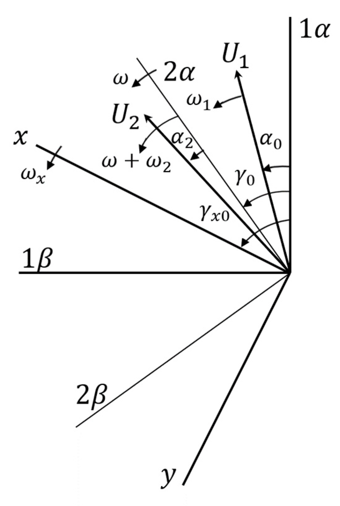
To generalize, we transform the equations of an electric machine into the x,y coordinate system. This system is common to both the stator and rotor and rotates at an arbitrary angular speed (see Figure 4).
The stator voltage balance equation, expressed in terms of space vectors U ˙ 1 , ψ ˙ 1 , I ˙ 1 , is given by:
U ˙ 1 = R 1 I ˙ 1 + d ψ ˙ 1 d t
To account for the rotational difference between the stationary 1 α , 1 β coordinate system and the rotating x , y coordinate system, the equation is multiplied by e j ( ω x t + γ x 0 ) .
ψ ˙ 1 ( x , y ) = ψ ˙ 1 e j ( ω x t + γ x 0 ) = ψ 1 m e j ( ω 1 ω x t + α 0 γ x 0 ϕ ;
U ˙ 1 ( x , y ) = U ˙ 1 e j ( ω x t + γ x 0 ) = U 1 m e j ( ω 1 t + α 0 ) e j ( ω x t + γ x 0 ) = = U 1 m e j ( ω 1 ω x t + α 0 γ x 0 ) ;
I ˙ 1 ( x , y ) = I ˙ 1 e j ( ω x t + γ x 0 ) = I 1 m e j ω 1 ω x t + α 0 γ x 0 ϕ .
where φ represents the displacement angle between the vectors ψ ˙ 1 and I ˙ 1 relative to U ˙ 1 at t = 0 .
The time derivative of the flux linkage is expressed as:
d ψ ˙ 1 ( x , y ) d t = d d t ψ ˙ 1 e j ( ω x t + γ x 0 ) = d ψ ˙ 1 d t e j ( ω x t + γ x 0 ) j ω x ψ ˙ 1 e j ( ω x t + γ x 0 ) .
Substituting, the stator voltage balance in the x, y coordinate system becomes:
U ˙ 1 ( x , y ) = R 1 I ˙ 1 ( x , y ) + d ψ ˙ 1 ( x , y ) d t + j ω x ψ ˙ 1 ( x , y ) .
Separating real and imaginary parts, the voltage balance equations in the x,y coordinate axes are:
U 1 x = d ψ 1 x d t ω x ψ 1 y + R 1 y + R 1 i 1 x U 1 y = d ψ 1 y d t ω x ψ 1 x + R 1 y + R 1 i 1 y
For the rotor windings, the voltage balance equation is:
U ˙ 2 = d ψ ˙ 2 d t + R 2 I ˙ 2 .
Multiplying by e j ( ω ω k ) t + γ 0 γ x 0 to account for the rotational difference between the 2α, 2β and x, y systems, and applying similar transformations, we obtain:
U ˙ 2 x , y = d ψ ˙ 2 x , y d t + j ω ω 2 ψ ˙ 2 x , y + R 2 I ˙ 2 x , y .
Breaking this into components yields:
U 2 x = d ψ 2 x d t ( ω ω x ) ψ 2 y + R 2 i 2 x U 2 y = d ψ 2 y d t ( ω ω x ) ψ 2 x + R 2 i 2 y .
By appropriately selecting the angular frequencies ω1, ω2, ω, ωx, the induction machine can be analyzed in any coordinate system.
A key feature of this model is the inclusion of rotational electromotive forces: ω x ψ 1 y , ω x ψ 1 x , ω ω x ψ 2 y , ω ω x ψ 2 x . In the x,y coordinate system (common to both stator and rotor), the machine windings behave as semi-fixed, resulting in flux linkages without alternating coefficients:
ψ 1 x = L 1 x i 1 x + L m i 2 x ψ 1 y = L 1 y i 1 y + L m i 2 y ψ 2 x = L m i 1 x + L 2 x i 2 x ψ 1 y = L m i 1 y + L 2 y i 2 y

3. Models of Induction Motors

3.1. Induction Motor Model in the αβ Coordinate System

For α,β ( ω x = 0) fixed coordinate system with axes linked to the stator, Equations (33) and (36) solving relative to flux linkages derivatives take the following form:
d ψ 1 α d t = U m cos τ R 1 i 1 a d ψ 1 β d t = U m cos τ R 1 i 1 β d ψ 2 α d t = R 2 i 2 α + ω ψ 2 β d ψ 2 β d t = R 2 i 2 β + ω ψ 2 α
The rotor speed variation is described by the following equation:
d ω d t = T e T l / T M
where T e is the electromagnetic torque, T l is the load torque, and T M represents the motor’s moment of inertia.
The current components are determined using the flux linkage expressions:
i 1 α = X 2 ψ 1 α X a d ψ 2 α i 1 α = X 2 ψ 1 β X a d ψ 2 β i 2 α = X 1 ψ 2 α X a d ψ 1 α i 2 β = X 1 ψ 2 β X a d ψ 1 β
where
= X 1 X 2 X a d X a d
The electromagnetic torque is given by:
T e = X a d i 1 α i 2 β i 1 β i 2 α
and the load torque is the following:
T l = S M ω 2 2 + S M C
where
ψ 1 β ,   ψ 1 α ,   ψ 2 β ,   ψ 1 α are the stator and rotor flux linkage components in the αβ coordinate system,
i 1 x ,   i 1 y ,   i 2 x ,   i 2 y are the stator and rotor current components in the αβ coordinate system,
ω is the rotor angular speed,
U m cos ( τ ) , U m sin ( τ ) are the stator applied voltage,
R 1 , R 2 , X 1 , X 2 , X a d are the induction motor parameters in per-unit values,
T e , T l are the electromagnetic and load torques, respectively,
S M , S M C are the motor’s variable and constant torques coefficients.
The developed induction motor model in the αβ coordinate system provides a framework for simulating various dynamic operating modes, including direct starting and direct starting with current displacement in the slots. This model (model I) enables direct comparisons between the single-phase simulation results and the experimental data, without additional transformations.

3.2. The Model of the Induction Motor in the d,q Coordinate System

Using Equations (33) and (36), we can express the induction motor model in matrix form as follows:
u 1 d u 1 q 0 0 = R a 0 0 0 0 R a 0 0 0 0 R 2 0 0 0 0 R 2 i 1 d i 1 q i 2 d i 2 q + ω 0 e l ψ 1 q ω 0 e l ψ 1 d ω x ω ψ 2 q ω x ω ψ 2 d + d d t ψ 1 d ψ 1 q ψ 2 d ψ 2 q ,
d ω d t = X a d i 2 d i 1 q i 2 q i 1 d T l ,
where flux linkages derivatives can be expressed as:
d d t i 1 d i i 1 q i 2 d i 2 q = C 1 R 1 + C 1 f 1 + C 1 X a d + C 1 X a d ω C 1 f 1 C 1 R 1 C 1 X a d ω + C 2 X a d C 3 R 1 X 1 f 2 C 2 X 1 f 3 X 1 f 2 + C 3 R 1 + f 3 C 2 X 1 i 1 d i 1 q i 2 d i 2 q + C 1 0 0 0 0 C 1 0 0 0 0 C 1 0 0 0 0 C 1 U 1 d U 1 q U 2 d U 2 q ,
where u 1 d , u 1 q stator applied voltages;
i 1 d , i 1 q , i 2 d , i 2 q stator and rotor currents components in the d , q coordinate system;
ψ 1 d , ψ 1 q , ψ 2 d , ψ 2 q stator and rotor flux linkages component in d , q coordinate system;
The constants are defined as:
C 1 = 1 X d = 1 X 1 X a d 2 X 2 ,   C 2 = R 2 X 2 C 1 ,   C 3 = X a d X 2 C 1 ,   f 1 = X 1 X a d 2 X 2 ω x + X a d 2 X 2 f 2 = ω C 3 ,   f 3 = C 1 X 1 ( ω ω x ) .
Thus, this model provides a framework for solving the induction motor (IM) equations in terms of currents. The IM model in the d,q coordinate system (referred to as model II) is expressed using current variables, enabling its integration into studies analyzing the motor’s impact on power supply systems.

3.3. The Model of the Induction Motor in the d,q Coordinate System in Flux Linkages

If Equations (33) and (36) are rewritten in terms of flux linkage derivatives, the system of equations takes the following form:
d ψ 1 d d t = U 1 d R 1 i d + ω ψ 1 q d ψ 1 q d t = U 1 q R 1 i q ω ψ 1 d d ψ 2 d d t = R 2 i 2 d + ( ω x ω ) ψ 2 d d ψ 2 q d t = R 2 i 2 q ( ω x ω ) ψ 2 d ,
The torque balance equation is given by:
T M d ω d t = T e T l ,
where the electromagnetic torque is expressed as:
T e = X a d i 2 d i 1 q i 2 q i 1 d .
The stator and rotor currents can be expressed in terms of flux linkages as:
i 1 d = X 2 ψ 1 d X a d ψ 2 d / i 1 q = X 2 ψ 1 q X a d ψ 2 q / i 2 d = X 1 ψ 2 d X a d ψ 1 d / i 2 q = X 1 ψ 2 q X a d ψ 1 q / ,
where = X 1 X 2 X a d X a d .
Equations (45)–(47) represent the mathematical model of the induction motor (IM) in terms of flux linkages. This IM model, expressed in the d,q coordinate system (referred to as model III) enables the analysis of motor operation in autonomous regimes, including scenarios where the motor operates independently or is connected to a power supply network with an infinitely large capacity.

3.4. Induction Motor Model in Flux Linkages with Rotor Windings Electromagnetic Time Constant in d,q Coordinate System

If Equations (33) and (36) are reformulated to include flux linkages with rotor windings’ electromagnetic time constant derivatives, the system of equations is as follows:
U d = d ψ 1 d d t ω ψ 1 q + R 1 i d U q = d ψ 1 q d t + ω ψ 1 d + R 1 i q 0 = d ψ 2 d d t ψ 1 d T R X a d T R i d + ψ 2 q ω 0 e l ω 0 = d ψ 2 q d t ψ 1 q T R + X a d T R i q ψ 2 d ω 0 e l ω ,
where T e the electromagnetic torque, is calculated as:
T e = X a d i 2 d i 1 q i 2 q i 1 d .
The currents can be expressed in terms of flux linkages:
i 1 d = ( X 2 ψ 1 d X a d ψ 2 d ) / i 1 q = ( X 2 ψ 1 q X a d ψ 2 q ) / i 2 d = ( X 1 ψ 2 d X a d ψ 1 d ) / i 2 q = ( X 1 ψ 2 q X a d ψ 1 q ) / ,
where = X 1 X 2 X a d X a d .
Model IV incorporates the rotor winding electromagnetic time constant, a critical parameter governing the evolution of flux linkages and currents within the rotor circuit during transient events. This time constant directly influences the motor’s response to rapid changes in voltage, load, or other external conditions. For example, during starting or voltage dips, it determines the decay rate of transient components and the stabilization of steady-state performance. By accounting for this parameter, Model IV enables accurate analysis of motor parameter variations during rundown regimes and transient phenomena, such as torque oscillations and current peaks. This detailed modeling is essential for motor protection and optimizing system performance, offering insights beyond those achievable with simpler models.

4. Induction Motor Starting Mode Modeling

To calculate the starting mode of an induction motor (IM), including current, rotational frequency, and electromagnetic torque under no-load conditions, the following IM models were used: model I—expressed in the α,β coordinate system, model II—in the d,q coordinate systems using currents, model III—in the d,q coordinate systems using flux linkages and model IV—in the d,q coordinate system using flux linkages with the rotor winding electromagnetic time constant.
For starting mode modeling, the parameters of a 3 kW induction motor with the following per unit (pu) values were used [76]: X1 = 0.057 pu, Xad = 3.4 pu, X2 = 0.1 pu, R1= 0.072 pu, R2 = 0.0487 pu, TM = 32.986.
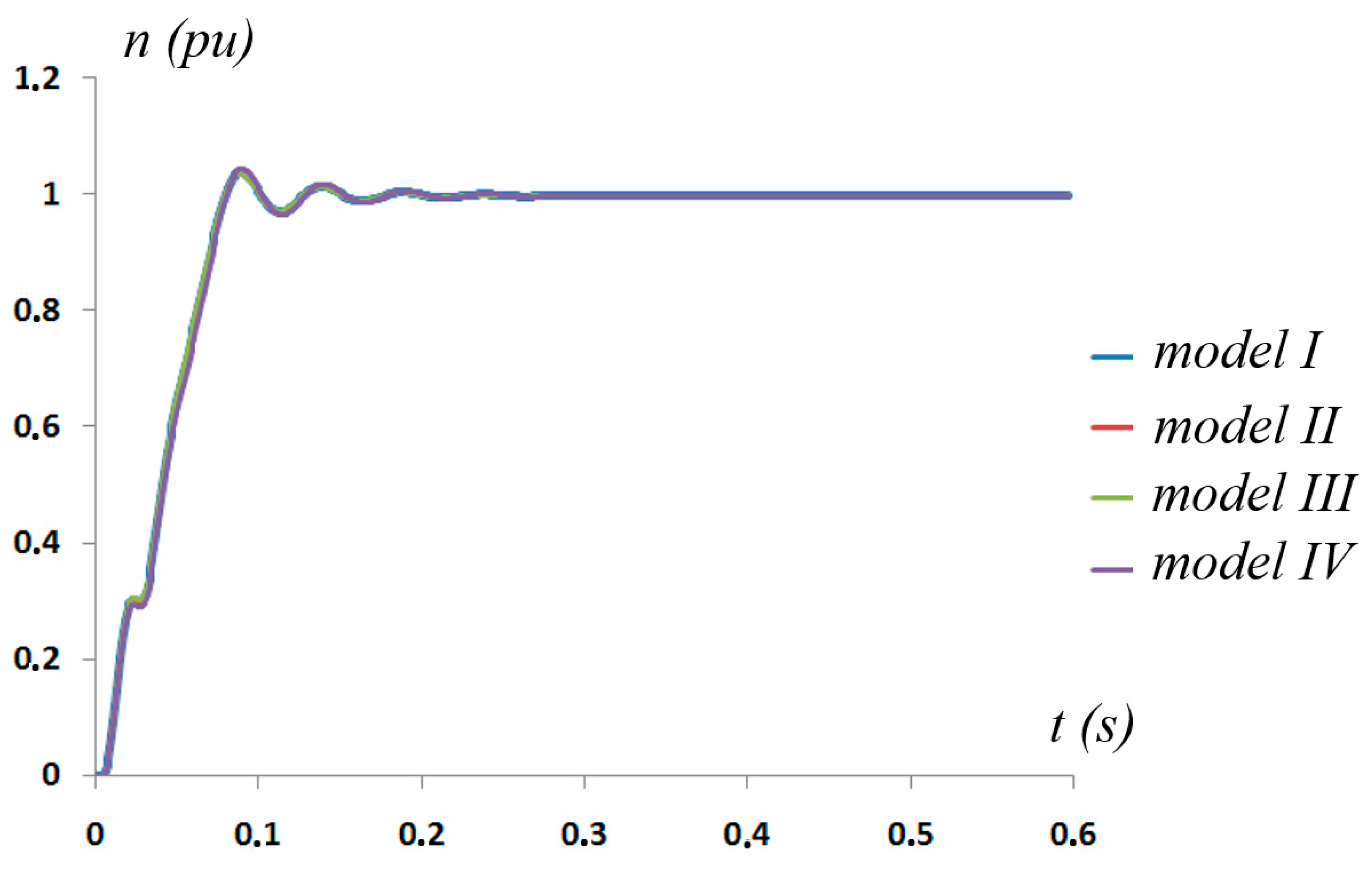
Figure 5 illustrates the rotational frequency characteristics of a 3 kW induction motor during starting mode under no-load conditions. The graph shows the rotor’s acceleration profile, demonstrating how the rotational frequency stabilizes as the motor reaches a steady-state operation.
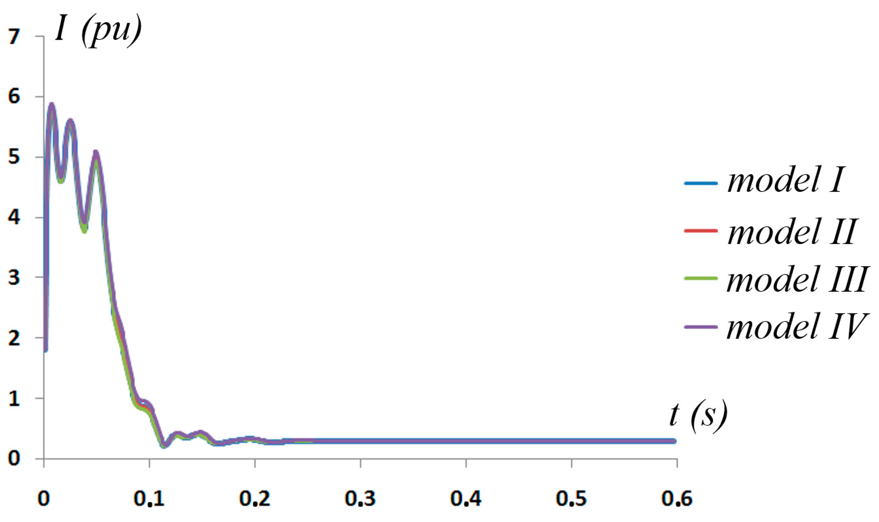
Figure 6 illustrates the current drawn by the induction motor during direct starting under no-load conditions. The graph highlight the initial high inrush current, which gradually decreases as the motor transitions to steady-state operation.
Figure 7 shows the variation in electromagnetic torque during the starting phase of the induction motor. The torque curve emphasizes the transient behavior before stabilizing at its no-load steady-state value.
Mathematical modeling of the IM starting mode, based on the models presented earlier in this paper, reveals that regardless of the coordinate system chosen (α,β or d,q) or the mathematical basis (currents, flux linkages, or flux linkages with rotor windings’ electromagnetic time constant), the modeling results are consistent and accurately represent real-world behavior. The results of the starting mode mathematical modeling using Model I were compared with experimental data from a test setup described in [22], which included measurements of current, rotational speed, and torque using specialized equipment. These comparisons demonstrated close alignment between modeled and experimental results, validating the model’s accuracy and reliability for analyzing IM starting dynamics.
The data tables in Appendix A show that the values of current, rotational frequency, and electromagnetic torque are in close agreement across the four models, particularly at later time instances. However, minor discrepancies are observed during the initial period, which can be attributed to transient effects. Despite these variations, the models converge to similar steady-state behavior, indicating that any of these models can be effectively used to simulate the dynamic regimes of induction motors, provided that the transient period is appropriately considered.
In addition to the no-load starting characteristics presented in Figure 5, Figure 6 and Figure 7, the four presented IM models can also simulate starting regimes for induction motors of various capacities, with different load characteristics and torque profiles. This flexibility ensures broad applicability of these models for analyzing and optimizing motor performance under diverse operational conditions.
A comparative summary of the four mathematical models is presented in Table 1. The table outlines the coordinate systems, key parameters simulated, and the strengths and limitations of each model. This summary provides additional context for understanding the unique features and applications of the models, helping to identify their suitability for different dynamic regimes of induction motor operation.
The choice of modeling approach affects both the computational complexity and the focus of the analysis. Current-based models are simpler and often preferred for analyzing motor impacts on power systems, as they directly relate to electrical network interactions. On the other hand, flux linkage-based models offer deeper insights into the internal electromagnetic behavior of the motor, making them more suitable for advanced control strategies and detailed transient analyses. Both approaches provide consistent results under equivalent conditions, but their selection depends on the specific objectives of the analysis, such as whether the focus is on external power supply interactions or intrinsic motor dynamics.
Before concluding, it is worth noting that the results of this study may be relevant for the development of other types of electric machines, as well as for applications involving advanced signal processing techniques, such as adaptive step-size forward–backward pursuit and acoustic emission-based health state assessment of high-speed train bearings [77].

5. Conclusions

This study developed and evaluated four distinct mathematical models for analyzing the dynamic behavior of induction motors during starting and transient processes. The models, based on the α,β and d,q coordinate systems with variations in current and flux linkage representation, produced consistent results regardless of the chosen modeling approach. This consistency was validated through numerical simulations and comparison with experimental data, confirming the accuracy and reliability of the models.
The implementation of the models in Fortran provided enhanced computational flexibility, allowing precise simulation of key parameters, such as rotational frequency, electromagnetic torque, and current profiles. Additionally, the models facilitate the analysis of motor operation under various conditions, including voltage unbalance, starting modes, and rundown scenarios.
A significant finding is that any of the four models can be effectively used to study induction motor dynamics without compromising accuracy. For instance, the rotational frequency results for the 3 kW induction motor during starting mode stabilized at approximately 0.998 pu across all models, demonstrating their consistency. The maximum inrush current during startup reached around 5.6 pu, gradually decreasing to steady-state values close to 0.292 pu. The electromagnetic torque exhibited transient peaks of about 2.46 pu before stabilizing near 0.05 pu. These values closely align with experimental results, further validating the accuracy and reliability of the proposed mathematical models for induction motor dynamics.
The choice of the appropriate model depends on the specific application. Model I is the simplest and is well-suited for basic analysis and direct experimental comparisons under no-load conditions. Model II is ideal for grid interaction studies, including voltage unbalance and power system analysis. For more detailed transient analyses and advanced control strategy development, Models III and IV are recommended, with Model IV being particularly effective for scenarios involving the rotor winding electromagnetic time constant, such as rundown and transient torque oscillations.
Future work will focus on utilizing the developed models to investigate induction motor operating modes under various conditions, including unbalanced voltages, asymmetry, rundown mode, switching mode, and other dynamic scenarios. This continued investigation aims to enhance the understanding of specific transient behaviors and refine the models for studying a broader range of dynamic regimes, providing valuable insights into the operational characteristics of induction motors.

Funding

M.K. thanks the Institute of Solid State Physics, University of Latvia (ISSP UL), which is as the Center of Excellence is supported through the European Union Horizon 2020 Framework Pro-gramme H2020-WIDESPREAD-01-2016-2017-TeamingPhase2 under grant agreement No. 739508, project CAMART2.

Institutional Review Board Statement

Not applicable.

Informed Consent Statement

Not applicable.

Data Availability Statement

The data and Fortran code supporting the findings of this study are available from the corresponding author upon reasonable request.

Acknowledgments

M.K. thanks Anatoli Popov for fruitful discussion.

Conflicts of Interest

The author declares no conflicts of interest.

Appendix A

Table A1, Table A2 and Table A3 present the calculated values for rotational frequency, current, and electromagnetic torque during the starting mode of a 3 kW induction motor. The results were obtained using four mathematical models:
Model I: Induction motor (IM) model in the α,β coordinate axes.
Model II: IM model in the d,q coordinate axes using currents,
Model III: IM model in the d,q coordinate axes using flux linkages,
Model IV: IM model in the d,q coordinate axes using flux linkages with the rotor time constant.
The tables highlight the motor’s transient and steady-state performance, with particular attention to how each model handles initial conditions and stabilization.
Table A1. IM rotation frequency n (pu).
t (s)Model I Model II Model III Model IV
0.010.0690.0690.070.067
0.050.6430.6430.650.625
0.11.0051.0051.0031.011
0.151.0011.0011.001.004
0.20.9990.9990.9981.00
0.250.9980.9980.9980.998
0.30.9980.9980.9980.998
0.350.9980.9980.9980.998
0.40.9980.9980.9980.998
0.450.9980.9980.9980.998
0.50.9980.9980.9980.998
0.550.9980.9980.9980.998
0.60.9980.9980.9980.998
Table A2. IM current I (pu).
t (s)Model IModel II Model III Model IV
0.015.5855.5855.5575.647
0.054.9774.9774.9255.087
0.10.7880.7890.7390.707
0.150.4010.4020.3850.405
0.20.32032103150341
0.250.30.3010.2990.312
0.30.2950.2960.2960.303
0.350.2930.2940.2940.3
0.40.2930.2930.2930.303
0.450.2920.2930.2930.298
0.50.2920.2930.2930.298
0.550.2920.2930.2930.298
0.60.2920.2930.2930.298
Table A3. IM electromagnetic torque T e (pu).
t (s)Model I Model II Model III Model IV
0.012.4612.4602.4912.392
0.051.4241.4241.4591.34
0.1−0.421−0.421−0.391−0.481
0.15−0.127−0.127−0.111−0.161
0.2−0.14−0.14−0.006−0.031
0.250.0270.0270.030.019
0.30.0410.0420.0430.038
0.350.0470.0470.0480.045
0.40.0490.0490.0490.048
0.450.0490.050.050.049
0.50.050.050.050.05
0.550.050.050.050.05
0.60.050.050.050.05

References

  1. Boldea, I. Induction Machines Handbook: Transients, Control Principles, Design and Testing; CRC Press: Boca Raton, FL, USA, 2020. [Google Scholar] [CrossRef]
  2. Gregor, R. (Ed.) Induction Motors: Applications, Control and Fault Diagnostics; BoD–Books on Demand, InTech: Rijeka, Croatia, 2015. [Google Scholar]
  3. Madhavan, S.; P B, R.D.; Gundabattini, E.; Mystkowski, A. Thermal Analysis and Heat Management Strategies for an Induction Motor, a Review. Energies 2022, 15, 8127. [Google Scholar] [CrossRef]
  4. Khumalo, N.S.; Memane, N.P.; Akuru, U.B. Performance and Safety Improvement of Induction Motors Based on Testing and Evaluation Standards. CES Trans. Electr. Mach. Syst. 2024, 8, 310–318. [Google Scholar] [CrossRef]
  5. Goman, V.; Prakht, V.; Kazakbaev, V.; Dmitrievskii, V. Comparative Study of Induction Motors of IE2, IE3 and IE4 Efficiency Classes in Pump Applications Taking into Account CO2 Emission Intensity. Appl. Sci. 2020, 10, 8536. [Google Scholar] [CrossRef]
  6. Orlova, S.; Konuhova, M.; Kamolins, E.; Otankis, R. Design of magnetic couplings for bioreactors: Analytical treatment and optimization. In Proceedings of the 2018 20th European Conference on Power Electronics and Applications (EPE’18 ECCE Europe), Riga, Latvia, 17–21 September 2018. [Google Scholar]
  7. Suleiko, A.; Vanags, J.; Konuhova, M.; Dubencovs, K.; Grigs, O. The application of novel magnetically coupled mixer drives in bioreactors of up to 15 m3. Biochem. Eng. J. 2020, 154, 107464. [Google Scholar] [CrossRef]
  8. Bezrukovs, V.; Bezrukovs, V.; Konuhova, M.; Bezrukovs, D.; Kaldre, I.; Popov, A.I. Numerical Simulations of Thermodynamic Processes in the Chamber of a Liquid Piston Compressor for Hydrogen Applications. Technologies 2024, 12, 266. [Google Scholar] [CrossRef]
  9. Terlip, D. Hydrogen Compressor Reliability Investigation and Improvement; Cooperative Research and Development Final Report; CRADA Number CRD-13-514 (No. NREL/TP-5400-66027); National Renewable Energy Lab. (NREL): Golden, CO, USA, 2016. [Google Scholar] [CrossRef]
  10. Bezrukovs, V.; Bezrukovs, V.; Konuhova, M.; Bezrukovs, D.; Berzins, A. Hydrogen hydraulic compression system for refuelling stations. Latv. J. Phys. Tech. Sci. 2022, 59, 96–105. [Google Scholar] [CrossRef]
  11. J Chapman, S. Electric Machinery Fundamentals; McGraw-Hill: New York, NY, USA, 2004. [Google Scholar]
  12. Agamloh, E.B.; Cavagnino, A. High efficiency design of induction machines for industrial applications. In Proceedings of the 2013 IEEE Workshop on Electrical Machines Design, Control and Diagnosis (WEMDCD), Paris, France, 11–12 March 2013; pp. 33–46. [Google Scholar] [CrossRef]
  13. IEA Energy Efficient End-Use Equipment (4E). Available online: https://www.iea-4e.org/emsa/ (accessed on 10 January 2025).
  14. Okoro, O.I.; Ogbuka, C.U.; Agu, M.U. Simulation of dc machines transient behaviors: Teaching and research. Pac. J. Sci. Technol. 2008, 9, 142–148. [Google Scholar]
  15. Beňová, M.; Dobrucký, B.; Šedo, J.; Praženica, M.; Koňarik, R.; Šimko, J.; Kuchař, M. A Novel Approach to Transient Fourier Analysis for Electrical Engineering Applications. Appl. Sci. 2024, 14, 9888. [Google Scholar] [CrossRef]
  16. Navarro-Navarro, A.; Ruiz-Sarrio, J.E.; Biot-Monterde, V.; Antonino-Daviu, J.A.; Becker, V.; Urschel, S. Application of Transient Analysis Techniques to Fault Diagnosis in Low- and Medium-Power Synchronous Machines. Machines 2023, 11, 288. [Google Scholar] [CrossRef]
  17. Mostajeran, E.; Amiri, N.; Ebrahimi, S.; Jatskevich, J. Electrical Machines in Electromagnetic Transient Simulations: Focusing on efficient and accurate models. IEEE Electrif. Mag. 2023, 11, 38–53. [Google Scholar] [CrossRef]
  18. Melkebeek, J.A. Transient Phenomena in Electrical Machines. In Electrical Machines and Drives. Power Systems; Springer: Cham, Switzerland, 2018. [Google Scholar] [CrossRef]
  19. Zhu, J.H.; Zhang, P.; Tan, L.; Gu, J.; Li, H. Improved MSTOGI-PLL with enhanced control under non-ideal grid voltage conditions. Electr. Power Syst. Res. 2025, 238, 111060. [Google Scholar] [CrossRef]
  20. Gnaciński, P.; Pepliński, M.; Muc, A.; Hallmann, D. Induction Motors Under Voltage Unbalance Combined with Voltage Subharmonics. Energies 2024, 17, 6324. [Google Scholar] [CrossRef]
  21. Fachini, F.; de Castro, M.; Bogodorova, T.; Vanfretti, L. Modeling of Induction Motors and Variable Speed Drives for Multi-Domain System Simulations Using Modelica and the OpenIPSL Library. Electronics 2024, 13, 1614. [Google Scholar] [CrossRef]
  22. Konuhova, M. Modeling of Induction Motor Direct Starting with and without Considering Current Displacement in Slot. Appl. Sci. 2024, 14, 9230. [Google Scholar] [CrossRef]
  23. Cureño-Osornio, J.; Alvarez-Ugalde, C.A.; Zamudio-Ramirez, I.; Osornio-Rios, R.A.; Dunai, L.; Tsurcanu, D.; Antonino-Daviu, J.A. Start-Up and Steady-State Regimes Automatic Separation in Induction Motors by Means of Short-Time Statistics. Electronics 2024, 13, 3850. [Google Scholar] [CrossRef]
  24. Kim, J.G. Soft Start Analysis of Induction Motor Using Current Phase Angle. J. Electr. Eng. Technol. 2022, 17, 1475–1480. [Google Scholar] [CrossRef]
  25. Hannan, M.A.; Ali, J.A.; Ker, P.J.; Mohamed, A.; Lipu, M.S.H.; Hussain, A. Switching Techniques and Intelligent Controllers for Induction Motor Drive: Issues and Recommendations. IEEE Access 2018, 6, 47489–47510. [Google Scholar] [CrossRef]
  26. Jidin, A.; Karim, K.A.; Rahim, K.; Raj, L.; Victor, L.; Ramahlingam, S.; Sutikno, T. A Review on Constant Switching Frequency Techniques for Direct Torque Control of Induction Motor. Indones. J. Electr. Eng. Comput. Sci. 2017, 7, 364–372. [Google Scholar] [CrossRef]
  27. Farhadi, M.; Fard, M.T.; Abapour, M.; Hagh, M.T. DC–AC Converter-Fed Induction Motor Drive With Fault-Tolerant Capability Under Open- and Short-Circuit Switch Failures. IEEE Trans. Power Electron. 2018, 33, 1609–1621. [Google Scholar] [CrossRef]
  28. Aree, P. Effects of unbalanced voltage on induction motor operating points under different load torque profiles. In Proceedings of the 2016 13th International Conference on Electrical Engineering/Electronics, Computer, Telecommunications and Information Technology (ECTI-CON), Chiang Mai, Thailand, 28 June–1 July 2016; pp. 1–4. [Google Scholar] [CrossRef]
  29. Laadjal, K.; Sahraoui, M.; Alloui, A.; Cardoso, A.J.M. Three-Phase Induction Motors Online Protection against Unbalanced Supply Voltages. Machines 2021, 9, 203. [Google Scholar] [CrossRef]
  30. Zhang, X.; Xu, G.; Chen, X.; Chen, R.; Chen, S.; Zhang, S. Three-Phase Unbalance Analysis Method Based on Three-Phase Motor Current Instantaneous Information. Appl. Sci. 2023, 13, 6127. [Google Scholar] [CrossRef]
  31. Abdo, A.; Siam, J.; Abdou, A.; Shehadeh, H.; Mustafa, R. Practical Test on the Operation of the Three-Phase Induction Motor under Single-Phasing Fault. Appl. Sci. 2024, 14, 4690. [Google Scholar] [CrossRef]
  32. Almounajjed, A.; Sahoo, A.K.; Kumar, M.K.; Bakro, M.W. Condition Monitoring and Fault Diagnosis of Induction Motor—An Experimental Analysis. In Proceedings of the 2021 7th International Conference on Electrical Energy Systems (ICEES), Chennai, India, 11–13 February 2021; pp. 433–438. [Google Scholar] [CrossRef]
  33. Niu, G.; Dong, X.; Chen, Y. Motor Fault Diagnostics Based on Current Signatures: A Review. IEEE Trans. Instrum. Meas. 2023, 72, 3520919. [Google Scholar] [CrossRef]
  34. Ganeriwala, S. Induction Motor Diagnostics Using Vibration and Motor Current Signature Analysis. In Special Topics in Structural Dynamics & Experimental Techniques; Allen, M., Blough, J., Mains, M., Eds.; Springer: Cham, Switzerland, 2024; Volume 5. [Google Scholar] [CrossRef]
  35. Mirzaeva, G.; Saad, K.I.; Jahromi, M.G. Comprehensive Diagnostics of Induction Motor Faults Based on Measurement of Space and Time Dependencies of Air Gap Flux. IEEE Trans. Ind. Appl. 2017, 53, 2657–2666. [Google Scholar] [CrossRef]
  36. Tang, J.; Yang, Y.; Blaabjerg, F.; Chen, J.; Diao, L.; Liu, Z. Parameter Identification of Inverter-Fed Induction Motors: A Review. Energies 2018, 11, 2194. [Google Scholar] [CrossRef]
  37. Antonelli, S.L.; Donolo, P.D.; Pezzani, C.M.; Quispe, E.C.; De Angelo, C.H. Identification of induction motor parameters using genetic algorithms. In Proceedings of the 2023 IEEE Workshop on Power Electronics and Power Quality Applications (PEPQA), Cali, Colombia, 4–5 October 2023; pp. 1–7. [Google Scholar] [CrossRef]
  38. Luo, X.; Zhao, J.; Xiong, Y.; Xu, H.; Chen, H.; Zhang, S. Parameter Identification of Five-Phase Squirrel Cage Induction Motor Based on Extended Kalman Filter. Processes 2022, 10, 1440. [Google Scholar] [CrossRef]
  39. Véliz-Tejo, A.; Travieso-Torres, J.C.; Peters, A.A.; Mora, A.; Leiva-Silva, F. Normalized-Model Reference System for Parameter Estimation of Induction Motors. Energies 2022, 15, 4542. [Google Scholar] [CrossRef]
  40. Udomsuk, S.; Areerak, K.; Areerak, T.; Areerak, K. Online Estimation of Three-Phase Induction Motor Parameters Using an Extended Kalman Filter for Energy Saving. Energies 2024, 17, 2115. [Google Scholar] [CrossRef]
  41. Bednarz, S.A.; Dybkowski, M. Estimation of the Induction Motor Stator and Rotor Resistance Using Active and Reactive Power Based Model Reference Adaptive System Estimator. Appl. Sci. 2019, 9, 5145. [Google Scholar] [CrossRef]
  42. Reddy, B.K.; Ayyagari, K.S.; Kumar, Y.P.; Giri, N.C.; Rajgopal, P.V.; Fotis, G.; Mladenov, V. Experimental Benchmarking of Existing Offline Parameter Estimation Methods for Induction Motor Vector Control. Technologies 2024, 12, 123. [Google Scholar] [CrossRef]
  43. Kłosowski, Z.; Fajfer, M.; Ludwikowski, Z. Reduction of the Electromagnetic Torque Oscillation during the Direct on Line (DOL) Starting of a 6 kV Motor by Means of a Controlled Vacuum Circuit-Breaker. Energies 2022, 15, 4246. [Google Scholar] [CrossRef]
  44. IEEE Std 3002.7-2018; IEEE Recommended Practice for Conducting Motor-Starting Studies and Analysis of Industrial and Commercial Power Systems. IEEE: New York, NY, USA, 2019; pp. 1–107. [CrossRef]
  45. Meshcheryakov, V.; Belousov, A. Development of a method for reducing starting currents and electromagnetic torque of a two-phase induction motor by delaying voltage supply. In Proceedings of the 2021 XVIII International Scientific Technical Conference Alternating Current Electric Drives (ACED), Ekaterinburg, Russia, 24–27 May 2021; pp. 1–5. [Google Scholar] [CrossRef]
  46. Bonnett, A.H. The impact that voltage and frequency variations have on AC induction motor performance and life in accordance with NEMA MG-1 standards. In Proceedings of the Conference Record of 1999 Annual Pulp and Paper Industry Technical Conference (Cat. No. 99CH36338), Seattle, WA, USA, 21–25 June 1999; pp. 16–26. [Google Scholar] [CrossRef]
  47. Chaban, A.; Łukasik, Z.; Popenda, A.; Szafraniec, A. Mathematical Modelling of Transient Processes in an Asynchronous Drive with a Long Shaft Including Cardan Joints. Energies 2021, 14, 5692. [Google Scholar] [CrossRef]
  48. Chen, X.; Gong, P. Transient and Steady-State Performance Improvement of IM Drives Based on Dual-Torque Model. Machines 2023, 11, 490. [Google Scholar] [CrossRef]
  49. Basak, B. Transient behaviour of three phase induction motor under supply interruption of one phase during starting. In Proceedings of the National Power Systems Conference-IIT, Kharagpur, India, 27–29 December 2002; pp. 259–262. [Google Scholar]
  50. Ahmed, A.; Ali, A.; Karrar, A.; Bowman, M.; Cooper, P. Estimating the Effects of Small Voltage and Frequency Changes on Industrial Induction Motor Loading. In Proceedings of the 2019 IEEE Power & Energy Society General Meeting (PESGM), Atlanta, GA, USA, 4–8 August 2019; pp. 1–5. [Google Scholar] [CrossRef]
  51. Saucedo-Dorantes, J.J.; Jaen-Cuellar, A.Y.; Perez-Cruz, A.; Elvira-Ortiz, D.A. Detection of Inter-Turn Short Circuits in Induction Motors under the Start-Up Transient by Means of an Empirical Wavelet Transform and Self-Organizing Map. Machines 2023, 11, 958. [Google Scholar] [CrossRef]
  52. Srndovic, M.; Fišer, R.; Grandi, G. Analysis of Equivalent Inductance of Three-Phase Induction Motors in the Switching Frequency Range. Electronics 2019, 8, 120. [Google Scholar] [CrossRef]
  53. Yabaci, S.B.; Atalay, A.K.; AhmetKocabaş, D. Design of an innovative mathematical model for transient response of three phase induction machine. In Proceedings of the 2016 National Conference on Electrical, Electronics and Biomedical Engineering (ELECO), Bursa, Turkey, 1–3 December 2016; pp. 344–348. [Google Scholar]
  54. Goolak, S.; Gubarevych, O.; Yermolenko, E.; Slobodyanyuk, M.; Gorobchenko, O. Mathematical modeling of an induction motor for vehicles. East. Eur. J. Enterp. Technol. 2020, 2, 104. [Google Scholar] [CrossRef]
  55. Hamola, O.Y.; Maday, V.S.; Vasylchyshyn, I.I. Mathematical Modelling of Starting Modes of Induction Motors with Squirrel-Cage Rotor. Electr. Eng. Electromech. 2021, 2, 9–15. [Google Scholar] [CrossRef]
  56. Sengamalai, U.; Anbazhagan, G.; Thamizh Thentral, T.M.; Vishnuram, P.; Khurshaid, T.; Kamel, S. Three Phase Induction Motor Drive: A Systematic Review on Dynamic Modeling, Parameter Estimation, and Control Schemes. Energies 2022, 15, 8260. [Google Scholar] [CrossRef]
  57. Le Roux, P.F.; Ngwenyama, M.K. Static and Dynamic Simulation of an Induction Motor Using Matlab/Simulink. Energies 2022, 15, 3564. [Google Scholar] [CrossRef]
  58. Alitasb, G.K. Assessment of Fractional and Integer Order Models of Induction Motor Using MATLAB/Simulink. Model. Simul. Eng. 2024, 2739649. [Google Scholar] [CrossRef]
  59. Singh, M.; Chaturvedi, D.K. Simulink Model of Induction Motor Under Faulty Conditions. 12 May 2024. [Google Scholar] [CrossRef]
  60. Dawood, A.; Ismeil, M.A.; Hussein, H.S.; Hasaneen, B.M.; Abdel-Aziz, A.M. An Efficient Protection Scheme Against Single-Phasing Fault for Three-Phase Induction Motor. IEEE Access 2024, 12, 6298–6317. [Google Scholar] [CrossRef]
  61. Bahgat, B.H.; Elhay, E.A.; Elkholy, M.M. Advanced fault detection technique of three phase induction motor: Comprehensive review. Discov. Electron. 2024, 1. [Google Scholar] [CrossRef]
  62. Boll, A.; Brokhausen, F.; Amorim, T.; Kehrer, T.; Vogelsang, A. Characteristics, potentials, and limitations of open-source Simulink projects for empirical research. Softw. Syst. Model 2021, 20, 2111–2130. [Google Scholar] [CrossRef]
  63. Blohm, P.; Herber, P.; Remke, A. Towards Quantitative Analysis of Simulink Models Using Stochastic Hybrid Automata. In Integrated Formal Methods. IFM 2024; Kosmatov, N., Kovács, L., Eds.; Lecture Notes in Computer Science; Springer: Cham, Switzerland, 2025; Volume 15234. [Google Scholar] [CrossRef]
  64. LinkedIn. What Are the Advantages and Disadvantages of Using Simulink? Available online: https://www.linkedin.com/advice/0/what-advantages-disadvantages-using-simulink (accessed on 5 January 2025).
  65. ResearchGate. Are You Familiar with Strengths and Weaknesses of Simulink to Simulate Power Systems? Available online: https://www.researchgate.net/post/Are-you-familiar-with-strengths-and-weaknesses-of-Simulink-to-simulate-power-systems (accessed on 5 January 2025).
  66. Metcalf, M.; Reid, J.; Cohen, M. Modern Fortran Explained: Incorporating Fortran 2018; Oxford University Press: Oxford, UK, 2018. [Google Scholar]
  67. Kopylov, I.P. Mathematical Models of Electric Machines; Mir Publishers: Moscow, Russia, 2001; p. 155. [Google Scholar]
  68. Dirba, J.; Ketners, K. Elektriskās mašīnas [Electrical Machines]; RTU Publishing House: Riga, Latvia, 2009. [Google Scholar]
  69. Muchande, S.; Kadam, A.; Unni, K.; Thale, S. Design and Implementation of a Direct Torque Control Space Vector Modulated Three Phase Induction Motor Drive. In Advances in Computing, Communication, and Control. ICAC3 2013; Unnikrishnan, S., Surve, S., Bhoir, D., Eds.; Communications in Computer and Information Science; Springer: Berlin/Heidelberg, Germany, 2013; Volume 361. [Google Scholar] [CrossRef]
  70. Qu, R.; Zhou, Y.; Milestones, D.L. Hotspots and trends in the development of electric machines. iEnergy 2022, 1, 82–99. [Google Scholar] [CrossRef]
  71. Fu, W.N.; Liu, Y. A unified theory of flux-modulated electric machines. In Proceedings of the 2016 International Symposium on Electrical Engineering (ISEE), Hong Kong, China, 14 December 2016; pp. 1–13. [Google Scholar] [CrossRef]
  72. Bramerdorfer, G.; Tapia, J.A.; Pyrhönen, J.J.; Cavagnino, A. Modern Electrical Machine Design Optimization: Techniques, Trends, and Best Practices. IEEE Trans. Ind. Electron. 2018, 65, 7672–7684. [Google Scholar] [CrossRef]
  73. Kljuchev, V.I. Theory of Electric Drives: Textbook for Universities; Energoizdat: Moscow, Russia, 1985. [Google Scholar]
  74. Slemon, G.R. Modelling of induction machines for electric drives. IEEE Trans. Ind. Appl. 1989, 25, 1126–1131. [Google Scholar] [CrossRef]
  75. Gao, J.D.; Zhang, L.Z.; Wang, X.H. AC Machine Systems; Tsinghua University Press: Beijing, China, 2009. [Google Scholar] [CrossRef]
  76. Sobolevskaya, A.E.; Shlaf, M.M.; Afonin, V.I.; Sobolevskaya, E.A. Asynchronous Motors of the 4A Series: Handbook; Energoizdat: Moscow, Russia, 1982. [Google Scholar]
  77. Han, D.; Qi, H.; Wang, S.; Hou, D.; Wang, C. Adaptive Stepsize Forward–Backward Pursuit and Acoustic Emission-Based Health State Assessment of High-Speed Train Bearings. Structural Health Monitoring. 2024. Available online: http://sage.cnpereading.com/paragraph/article/?doi=10.1177/14759217241271036 (accessed on 28 January 2025).
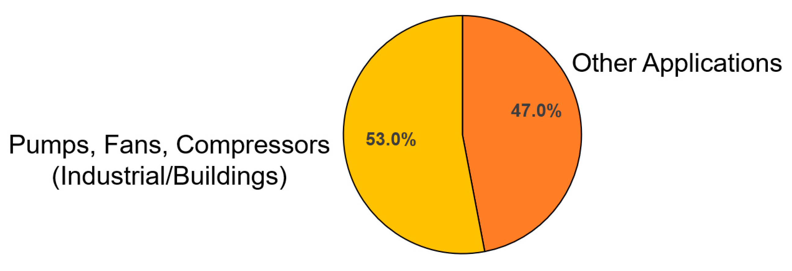
Figure 1. Global electricity consumption by electric motors.
Applsci 15 01527 g001
Figure 2. Current space vector.
Applsci 15 01527 g002
Figure 3. Generalized electric machine scheme.
Applsci 15 01527 g003
Figure 4. Coordinate system and voltages space vectors.
Applsci 15 01527 g004
Figure 5. Rotational frequency during the starting mode of a 3 kW induction motor under no-load conditions.
Applsci 15 01527 g005
Figure 6. Current drawn during direct starting of a 3 kW induction motor under no-load conditions.
Applsci 15 01527 g006
Figure 7. Electromagnetic torque variation during the starting phase of a 3 kW induction motor under no-load conditions.
Applsci 15 01527 g007
Table 1. Comparative summary of the four mathematical models for induction motor analysis.
ModelCoordinate System TypeKey Parameters SimulatedKey FeaturesApplications
I , β Rotational frequency, current, torqueSimple implementation, direct experimental comparisonSuitable for basic dynamic studies and starting scenarios under no-load
II d , q (Current)Rotational frequency, current, torqueEnables integration of the motor’s mathematical model to evaluate its impact on the power supply systemSuitable for analyzing voltage unbalance, grid interaction, and power system effects during starting
III d , q (Flux linkage)Rotational frequency, current, torque, flux linkagesSupports the analysis of autonomous operation regimes for motors fed by a power supply system with infinite capacityEffective for stand-alone motor analysis and advanced control strategy development
IV d , q (Flux linkages with rotor constant)Parameter variations during rundownAnalyzes motor parameter changes during rundown, emphasizing the rotor windings’ electromagnetic time constant.Useful for studying transient torque oscillations and motor response during rundown scenarios
Disclaimer/Publisher’s Note: The statements, opinions and data contained in all publications are solely those of the individual author(s) and contributor(s) and not of MDPI and/or the editor(s). MDPI and/or the editor(s) disclaim responsibility for any injury to people or property resulting from any ideas, methods, instructions or products referred to in the content.