Abstract
This paper presents the process of automated designing and parametric modeling of excavator buckets using the CAD system. A methodology has been developed that covers all stages of design, from the creation of 3D models of the parts, sub-assemblies, and assemblies to the generation of design documentation, using template files. The presented approach allows the creation of parametric models with multiple configurations, which cover different variants of the products according to their technical characteristics and purpose. This paper describes in detail the technological process, including the manufacture of parts and the assembling of sub-assemblies, in accordance with modern production requirements. Bucket classification according to excavator operating weight is included. Parametric modeling of the main components, such as the base and upper part of the bucket, is also described. In addition, an algorithm for automation of design documentation has been developed that integrates PDM systems for engineering data management. Using the presented methodology leads to a reduction in the volume of created documentation and optimizes the design process, providing the opportunity for rapid adaptation to various client requirements. Data management within a PDM system ensures centralized storage, actuality, and accessibility of information, which contribute to more efficient production and management of product data.
1. Introduction
This paper introduces the process of developing excavator buckets with a CAD system. The parts, sub-assemblies, and assembly of the bucket are parametrically designed. Different bucket models differ in their purpose, dimensions, and construction. The buckets are mounted on excavators and used for excavation work [1,2].
The bucket is designed and developed with the CAD system SolidWorks 2022 [3]. Using the CAD system significantly facilitates the process of developing the product. The design is performed in the three-dimensional space. Three-dimensional models of the parts, sub-assemblies, and assemblies are developed. The process of creating the design documentation is automated through the use of template files.
2. Literature Review
2.1. Parametric Modeling of Products with a CAD System
Three-dimensional models of parts, sub-assemblies, and assemblies are created through CAD systems. Design documentation is being developed—part drawings, assembly drawings, assembly specifications, and individual product specifications. Three-dimensional models can be used to create new design documentation. In 3D models of the parts and assemblies, the additional information is set by attributes (users and systems ones). The information from the attributes can be used for documentation management with a PDM system, as well as by other departments in a company with an ERP system [3,4,5,6].
Parametric modeling is used when the designed products have many versions and varieties. A single 3D model is created, where different versions of the product are presented with configurations. This results in a small amount of design documentation for a specific product. The big amount of documentation can cause many problems, for example, how to manage, organize, classify, and archive the documentation; who has the right to change and update it; the documents should always be with the latest version; and which other departments of the company have access to this documentation and the specialized information they are interested in [5,6].
Parametric modeling reduces the time of the design process and increases its efficiency. Design automation is achieved, which means that designers do not have to redesign the product when there is a change in the dimensions of the model. Engineers can model parametrically dimensions of the model, geometric constructions in the model (Features), constraints between parts in an assembly (Mates), etc. All of these parameters can be adjusted by making a few minor changes. In this way, product variants are created very quickly compared to the traditional modeling approach.
High accuracy is achieved in product modeling. Various algorithms are used in the creation of 3D models, which leads to a reduction in modeling errors.
Parametric modeling creates variations of 3D models and assemblies. It can be easily integrated into various manufacturing processes, which leads to faster product manufacturing.Parametric modeling is used for structural analysis or for analyzing the kinematics of machines. The reason is the ability to quickly process extremely complex geometric data.
2.2. Design Documentation Management Through PDM System, Application of ERP Systems
CAD systems are used to develop a large volume of design documentation—3D models, drawings, specifications, etc. Specialized systems, like PDM and ERP systems, are used to manage and maintain it. To manage the design documentation of the products considered in this publication, the PDM system SolidWorks PDM 2022 and the ERP system RDS ERP are used [3,4].
Product Data Management (PDM) systems are specialized software used to manage product data. The term “product data” means all information related to the product. PDM systems manage arrays of data and information necessary for the design, manufacture, and assembling of the products, as well as for their maintenance. The functionalities of PDM systems have been improved and, in addition to the Design and Engineering Departments, they are now used by other departments such as Supplies, Production, and Maintenance. This means that PDM systems are developed to manage and control the huge volume of electronic data created by CAD/CAM/CAE systems.
Enterprise Resource Planning (ERP) systems are used in all processes necessary for the functioning of a company—people management, finances, production, availability of materials or products, supply system, services, orders, etc. One of the main functions of ERP systems is the shared database, i.e., the employees from different departments operate with the same information for their specific needs.
Both systems are part of the so-called Product Lifecycle Management (PLM). This means that a specific product is tracked from the creation of the product concept to the end of its life cycle.
2.3. Designing Buckets for Excavators
The design of the discussed buckets is a long process, which is implemented in many stages. Each stage has its own specific characteristics that can be presented in the following sequence [7]:
PRELIMINARY PHASE
- -
- Preliminary design—CAD software SolidWorks 2022 is used to model the parts, sub-assemblies, and assemblies of the designed bucket model;
- -
- Simulation inspections—the buckets are inspected with the Finite Element Method;
- -
- Three-dimensional model adjustments—depending on the results obtained during the previous stage, the necessary structural changes are made to the parts, sub-assemblies, and assemblies of the bucket;
- -
- Production of the preliminary prototypes—a real prototype of the bucket is produced;
- -
- Conducting prototype tests—prototype tests are carried out in real conditions.
DESIGN PHASE
- -
- Adjustments to 3D models and drawings—based on the results from the testing stage, the necessary design changes are made to the parts, sub-assemblies, and assemblies of the bucket;
- -
- Simulation inspections—reverification of the bucket using the Finite Element Method;
- -
- Production of the design prototypes—a real prototype of the bucket is produced;
- -
- Conducting prototype tests—prototype tests are carried out in real conditions;
- -
- Design freeze—the design process of the product is finalized.
INDUSTRIALIZATION PHASE
- -
- Final modeling—3D models of the parts, sub-assemblies, and assemblies of the bucket are finalized and drawings and specifications are developed;
- -
- Engineering Pilot—mass production technologies are used to manufacture the bucket;
- -
- Testing and Certification—the produced buckets are tested and certified.
PRODUCT LAUNCH
- -
- Start of production—serial production of the bucket begins.
This publication will only consider 3D modeling of products or modification of already created 3D files by using the capabilities of modern CAD systems. Emphasis will be placed on the capabilities of parametric modeling of buckets and on the automated creation of design documentation (drawings of parts, drawings of assemblies, and specifications). The CAD system used is SolidWorks 2022 [3].
Regardless of the type of CAD system used, the principles of modeling are the same. Popular CAD systems for modeling and simulations in 3D space are Autodesk Inventor [8], Solid Edge [9], Creo [10], CATIA [11], Altair Inspire [12], and others.
The aim of using CAD systems is to increase the efficiency of engineering work by reducing design time and the possibility of errors. This can only be achieved through automation of product design. Another effect is to reduce the volume of design documentation.
2.4. Bucket Classification
Depending on the operational weight of the excavator, a classification of the buckets by classes was made (Table 1). Each bucket, depending on its class, differs in shape, dimensions, length, volume, and other specific indicators [1,2,13,14,15,16,17,18,19,20,21,22,23].

Table 1.
Classification of buckets, depending on the operating weight of the excavator.
Excavator buckets are characterized by the following features, which 3D models must also possess: bucket length; attachment for establishing the arm of the excavator; and type, size, and number of used teeth.
Depending on the class, the length of the buckets is from 600 mm to 1500 mm and, for larger classes, it reaches up to 2000 mm. The excavator arm is attached to the bucket attachment holes using pins. The bucket attachment is different for all the models of excavators. The type and size of the teeth depends on the class of the bucket and the customer requirements, and their number is determined by the length of the bucket.
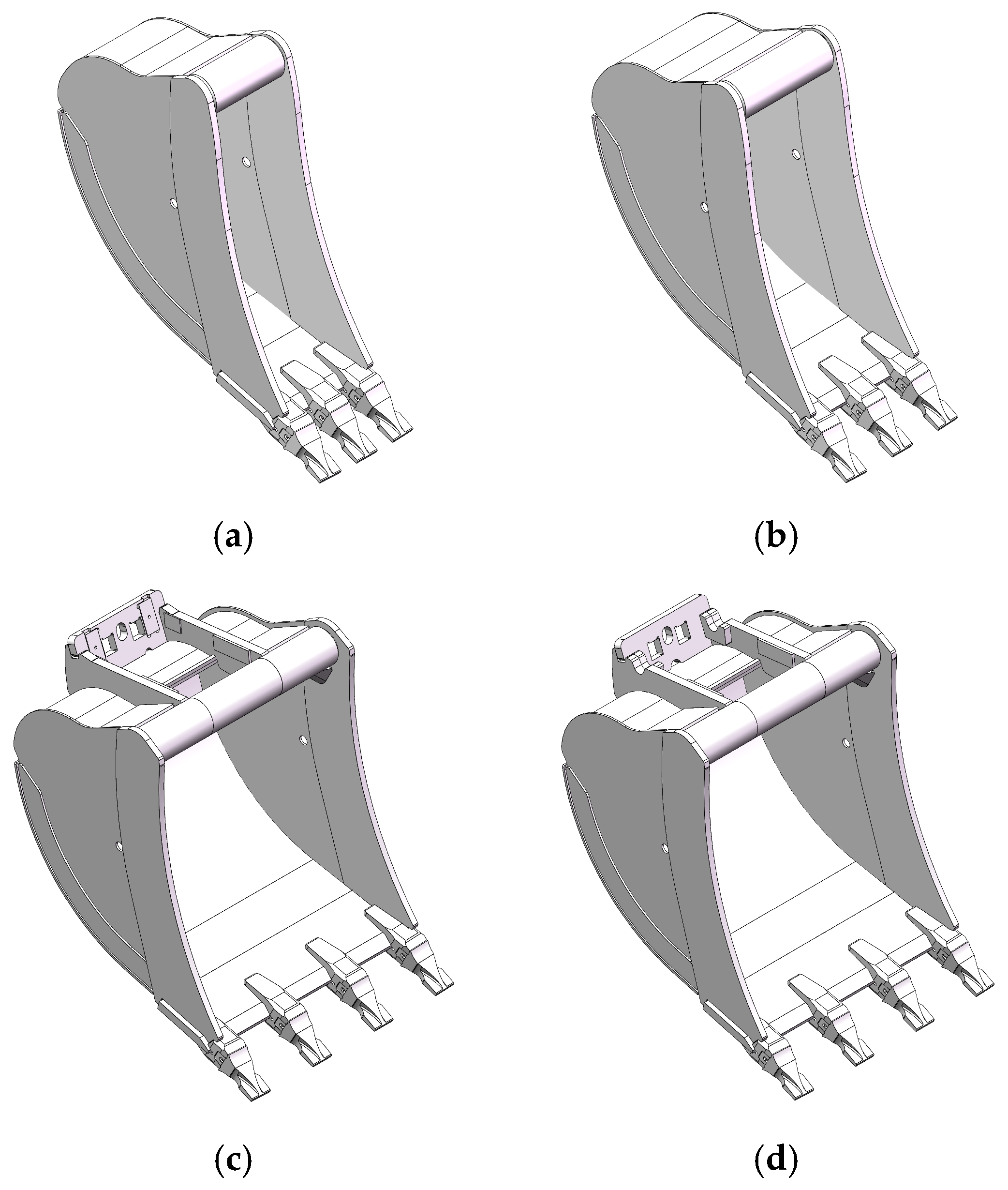
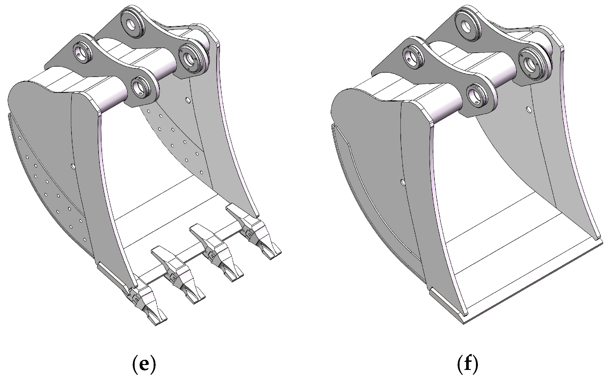
It should be noted that it is possible to manufacture special bucket designs [1,2,13]. For this purpose, standard designs are used, to which the necessary changes are made. This happens often, since sometimes buckets are used under specific operating conditions that require specialized designs, which are different from standard models. Special bucket designs are shown in Figure 1. These are, for example, buckets with a length of 400 mm and 500 mm, buckets with specialized attachments, for mounting the quick-change devices (Quick Couplers), buckets with holes on the side surfaces, buckets without teeth, etc.
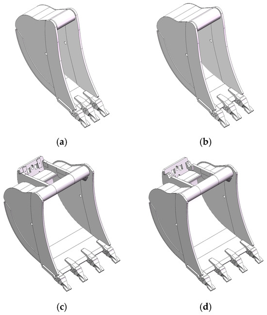
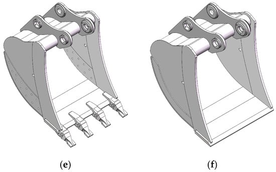
Figure 1.
Special bucket designs class D: (a) 400 mm; (b) 500 mm; (c) 1000 mm—QC (Quick Coupler); (d) 1000 mm—QC1 (Quick Coupler 1); (e) 1000 mm—with holes; (f) 1000 mm—without teeth.
According to the classification presented in Table 1, multiple 3D models need to be developed as follows for:
- -
- Each bucket length for each class;
- -
- All types of bucket attachments used by various excavators;
- -
- Each different tooth model.
In conclusion, it can be said that, with so many different versions and variations of bucket designs, the task of designing them becomes very difficult, both in terms of the huge amount of work involved in the design and in terms of the complexity of the work and control of the entire work process.
A certain product can be designed by applying two main methods—traditional modeling or parametric modeling. Both approaches are applied in practice. Depending on the products being developed, the method to be used is also chosen.
In addition, the development of 3D models must be consistent with the technology for manufacturing the buckets, as well as with the possibility of using the models from the PDM and ERP system.
2.5. Bucket Manufacturing Technology
The bucket manufacturing technology includes several stages.
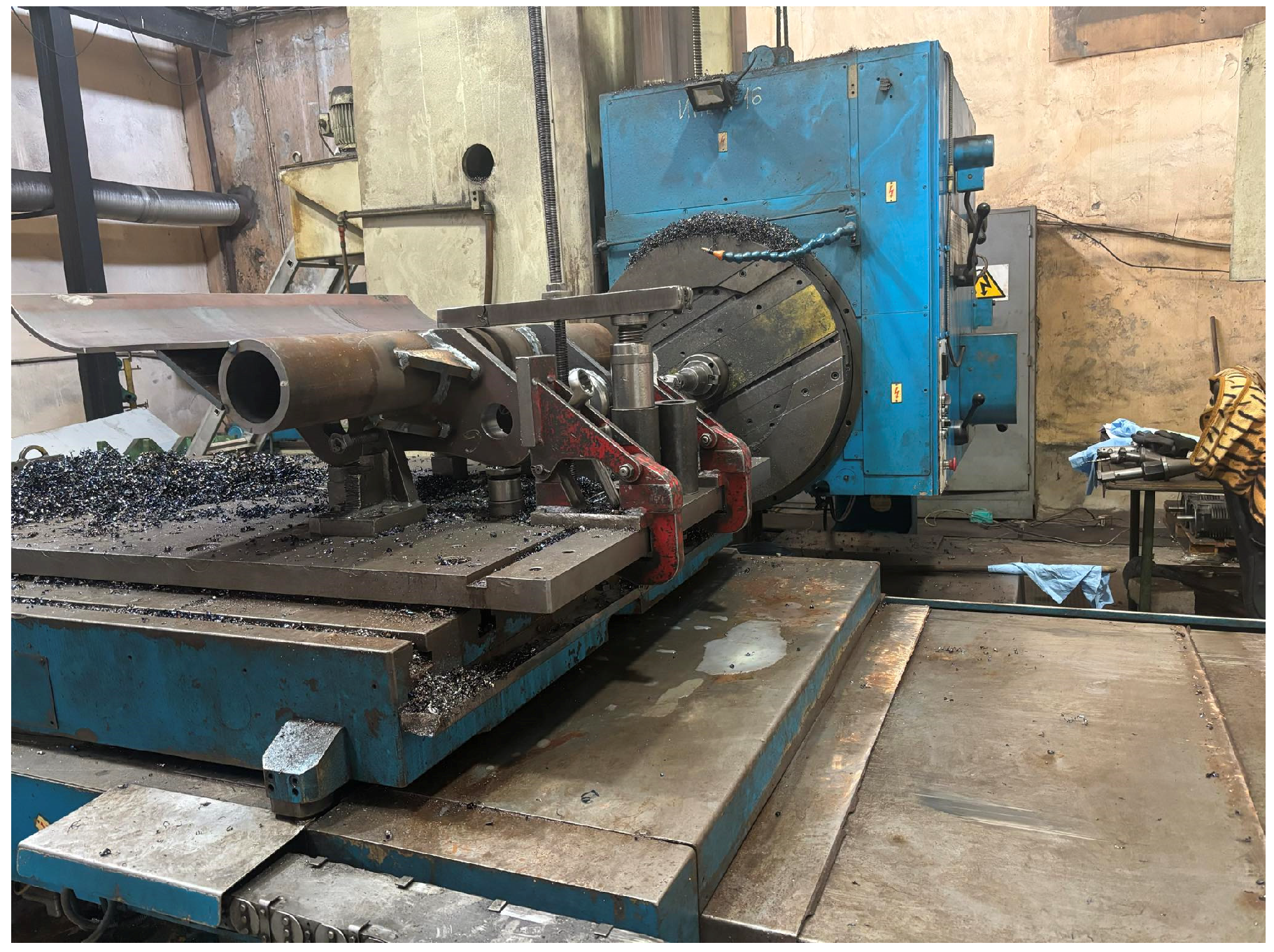
The first stage is manufacturing the upper part of the bucket together with the backet attachment. The parts that are made of sheet metal are cut from sheet metal with the appropriate thickness, after which some of them are machined on CNC machines (Figure 2) [24,25], and others are bent to appropriate shape and size. Other parts are cut from tubes with the appropriate dimensions; then, they are machined on lathes machines.
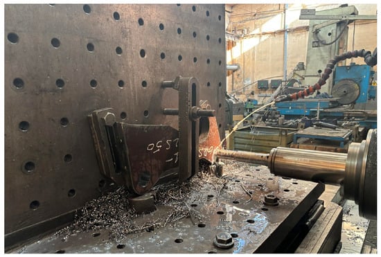
Figure 2.
Machining of the ear part from the backet attachment of the upper part.
All the parts are assembled with a fixture, tack welded, and welded. The upper part is machined on a machining center; the mounting holes are machined (Figure 3) [24,25]. Specialized CAM software is used to create the machining program—SolidWorks CAM 2022 [3].

Figure 3.
Machining of the mounting holes of the upper part.
The second stage is assembling the entire bucket using a fixture. The upper part is installed on the fixture and all other parts of the bucket are added. The parts are tack welded. The bucket is removed from the fixture and welded. After welding the bucket, the teeth are assembled and welded. The last stage is the control of the dimensions of the bucket. The integrity and quality of the weld beads are checked.
3. Parametric Modeling of Excavator Buckets
This publication presents an approach to improve the efficiency of the product design process by using parametric modeling. The CAD system SolidWorks 2022 was used [3].
The SolidWorks CAD system enables parametric modeling through parametric tables or through configurations.
The capabilities of MS Excel are used in the modeling using parametric tables. Parts, sub-assemblies, and assemblies are configured using tables in which values of the parameters are set. Formulas can be used and calculations can be made.
In configuration modeling, configurations are created in parts, sub-assemblies, and assemblies. The values of the parameters are set in the configurations. The publication discusses the method of parametric modeling through using configurations. For each of the bucket classes, a single 3D model has been developed that is parametrically modeled.
To illustrate parametric modeling, a class D bucket will be considered. This bucket class is for excavators from 17 to 22 t, which are widely used in practice.
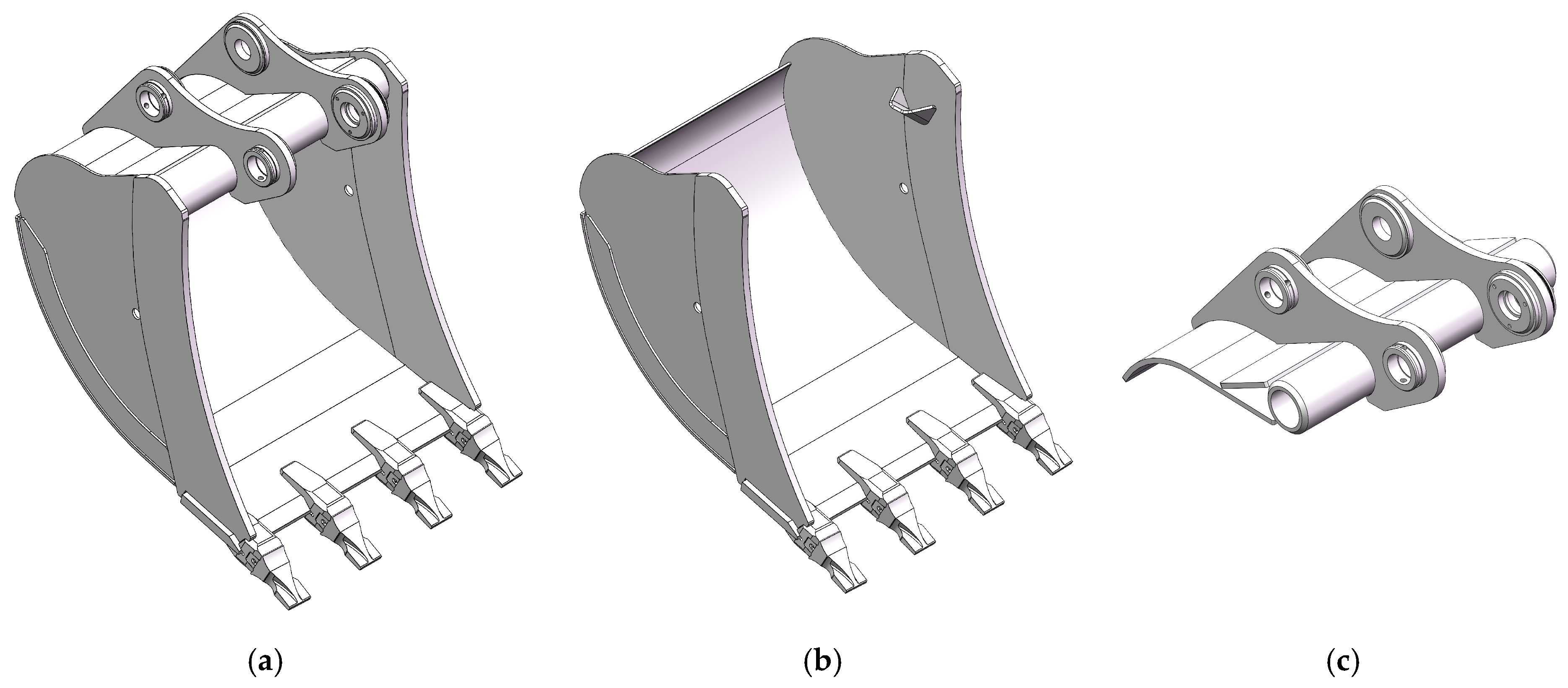
Figure 4 shows the 3D model of the bucket considered in the publication.

Figure 4.
Excavator bucket class D: (a) 3D model of the bucket; (b) base part; (c) upper part.
The 3D model is composed of two sub-assemblies—a base part, including parts of the bucket and teeth, and an upper part, including all other parts and the backet attachment. Regardless of the bucket class, every 3D bucket model consists of these two basic sub-assemblies.
Each of the parts from the sub-assemblies is developed by using different 3D modeling commands—Extruded Boss/Base, Revolved Boss/Base, Extruded Cut, Revolved Cut, etc. Parts that are made from sheet metal are created using the module Sheet Metal; in this way, their unfolding is obtained. The parts are assembled into individual sub-assemblies, which are assembled into the assembly of the bucket [13].
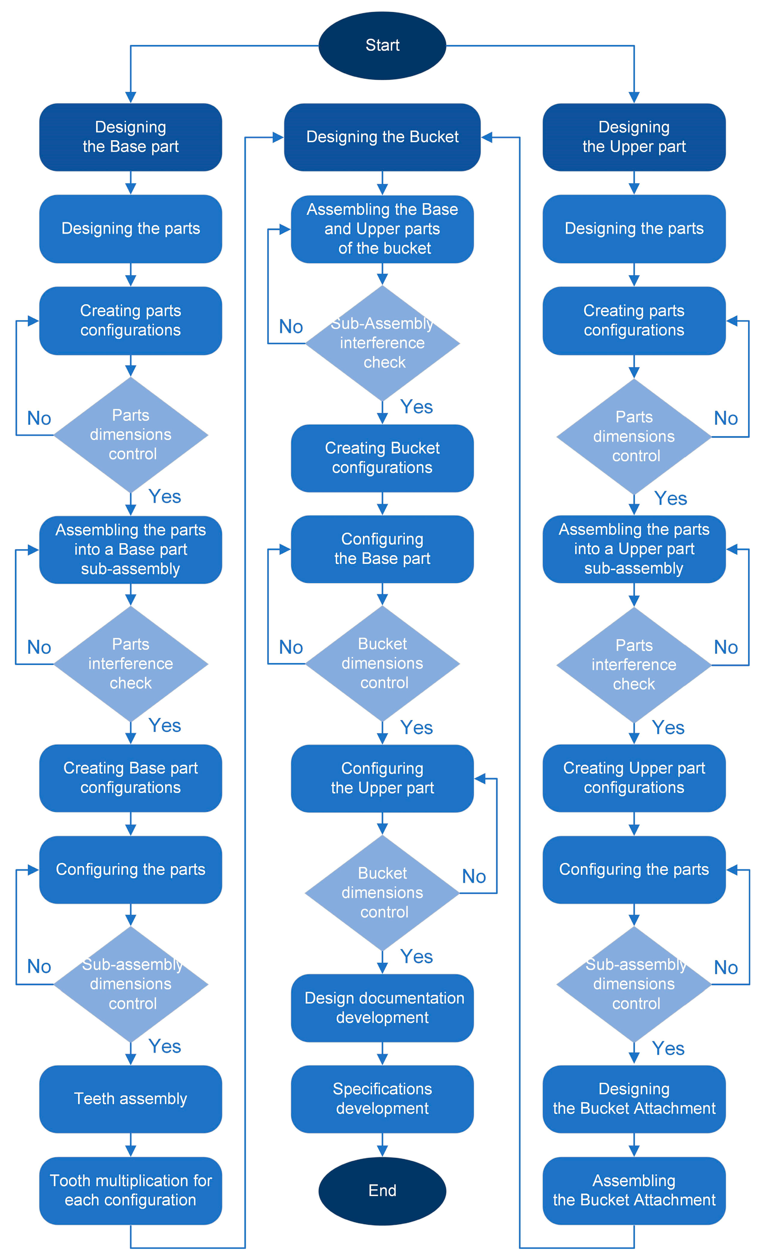
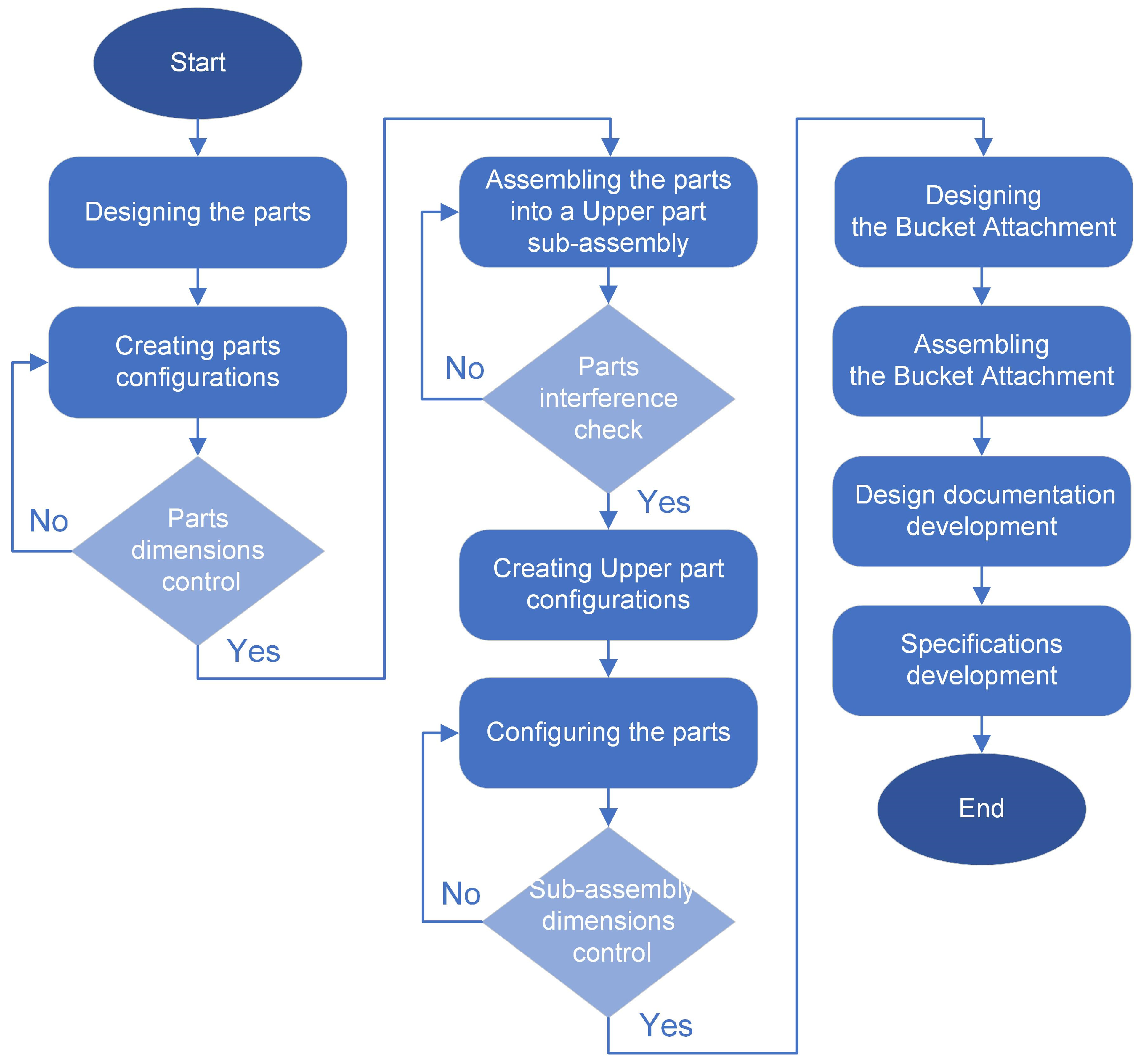
When products are developed and modeled with a CAD system, it is appropriate to use a specific design methodology. This makes the modeling process easier and reduces the time required for designing the elements. Figure 5 shows a summarized algorithm of the methodology for designing excavator buckets.
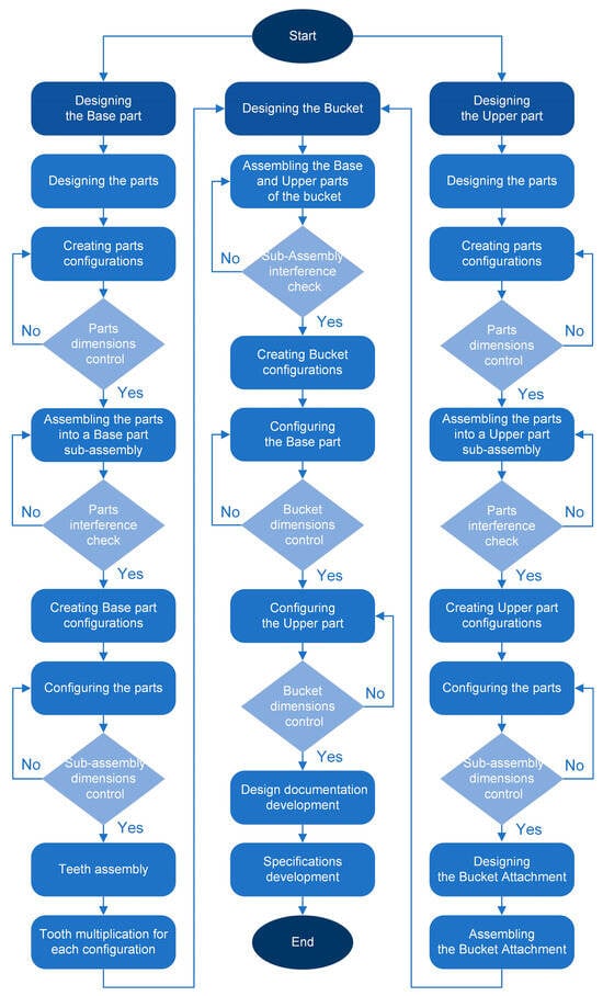
Figure 5.
Excavator bucket design algorithm.
3.1. Parametric Modeling of Base Part
Figure 6 shows the algorithm used to design the base part.
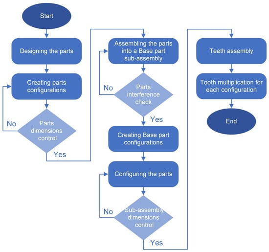
Figure 6.
Base part design algorithm.
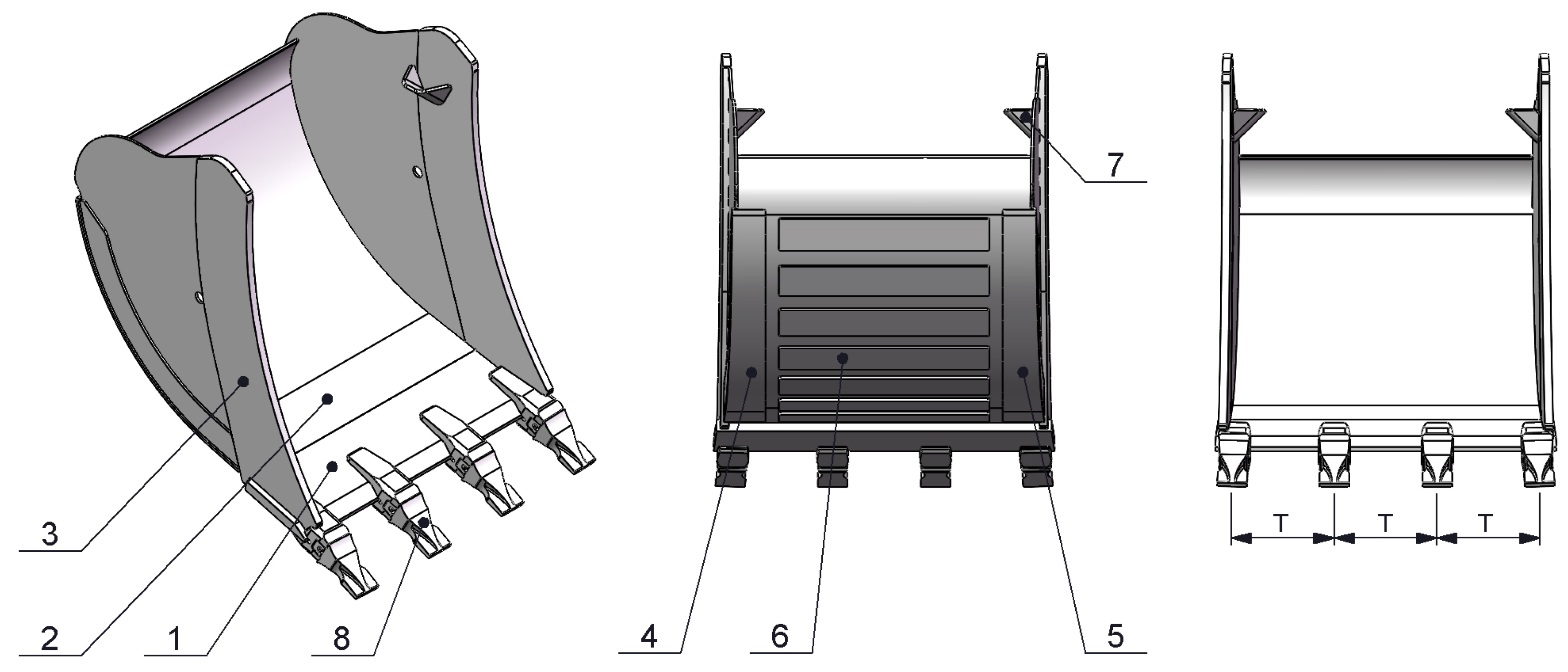
The 3D model of the base part is parametrically modeled through configurations and Figure 7 shows its components.
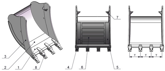
Figure 7.
Components of the base part. 1—Blade, 2—Bottom, 3—Side, 4—Left Rib, 5—Right Rib, 6—Horizontal Rib, 7—Internal Rib, 8—Teeth.
Parts with positions 1, 2, and 6 are parametrically modeled and they have different length configurations. This sub-assembly contains three parts that are structurally identical but differ in length.
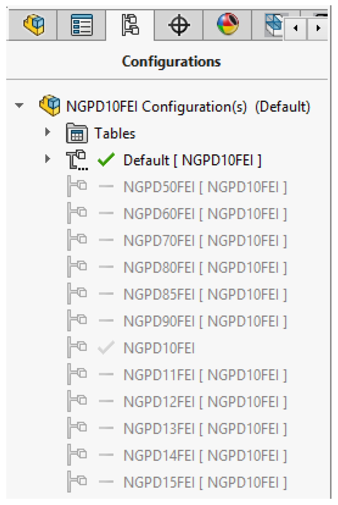
To model parametrically the 3D model of the base part, configurations are created in the Configuration Manager (Figure 8). Each configuration represents a different length of the base part. Base parts differ in length—from 500 mm (NGPD50FEI) to 1500 mm (NGPD15FEI).

Figure 8.
Configurations in the 3D model of the base part.
The next step is to configure the parts in the assembly of the base part. Parts with positions 1 (Blade), 2 (Bottom), and 6 (Horizontal Rib) contain configurations with different lengths. For each configuration of the base part, the corresponding configuration of the parts is set.
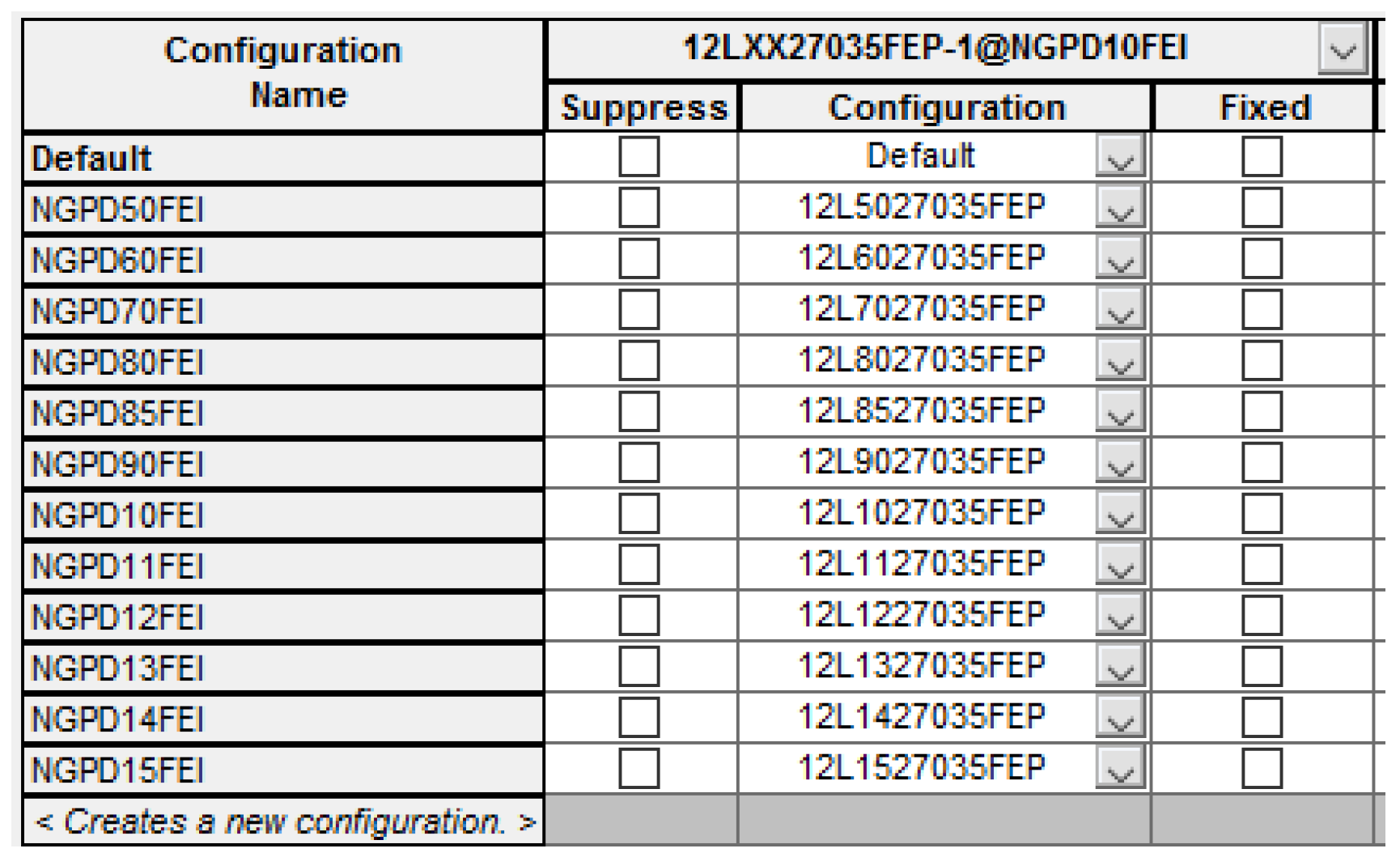
Figure 9 shows an example of the configurations of the base part and the specified configurations of the blade part. For the respective lengths of the base part, the blade part has the following configurations—from 500 mm (12L5027035FEP) to 1500 mm (12L1527035FEP).
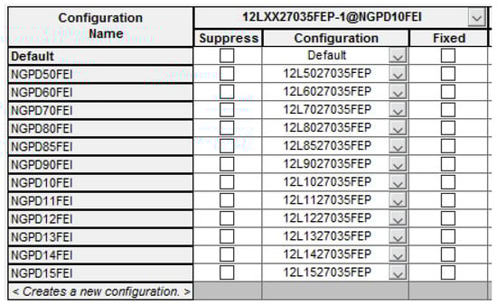
Figure 9.
Configuring the blade part.
A single 3D model of the blade part has been developed. Configuring the blade part involves setting different values for its length in the corresponding configuration (Table 2). In this case, parametric modeling is implemented by configuring a dimension from the 3D model of the part.
Table 2.
Configurations of the blade part.
If the part is developed using the traditional modeling approach, a different 3D model of the blade part with the corresponding length must be modeled for each bucket model. In the case of class D buckets, 12 different 3D models of the part must be designed. Modeling multiple parts is a prerequisite for making errors. In addition, the modeling time increases.
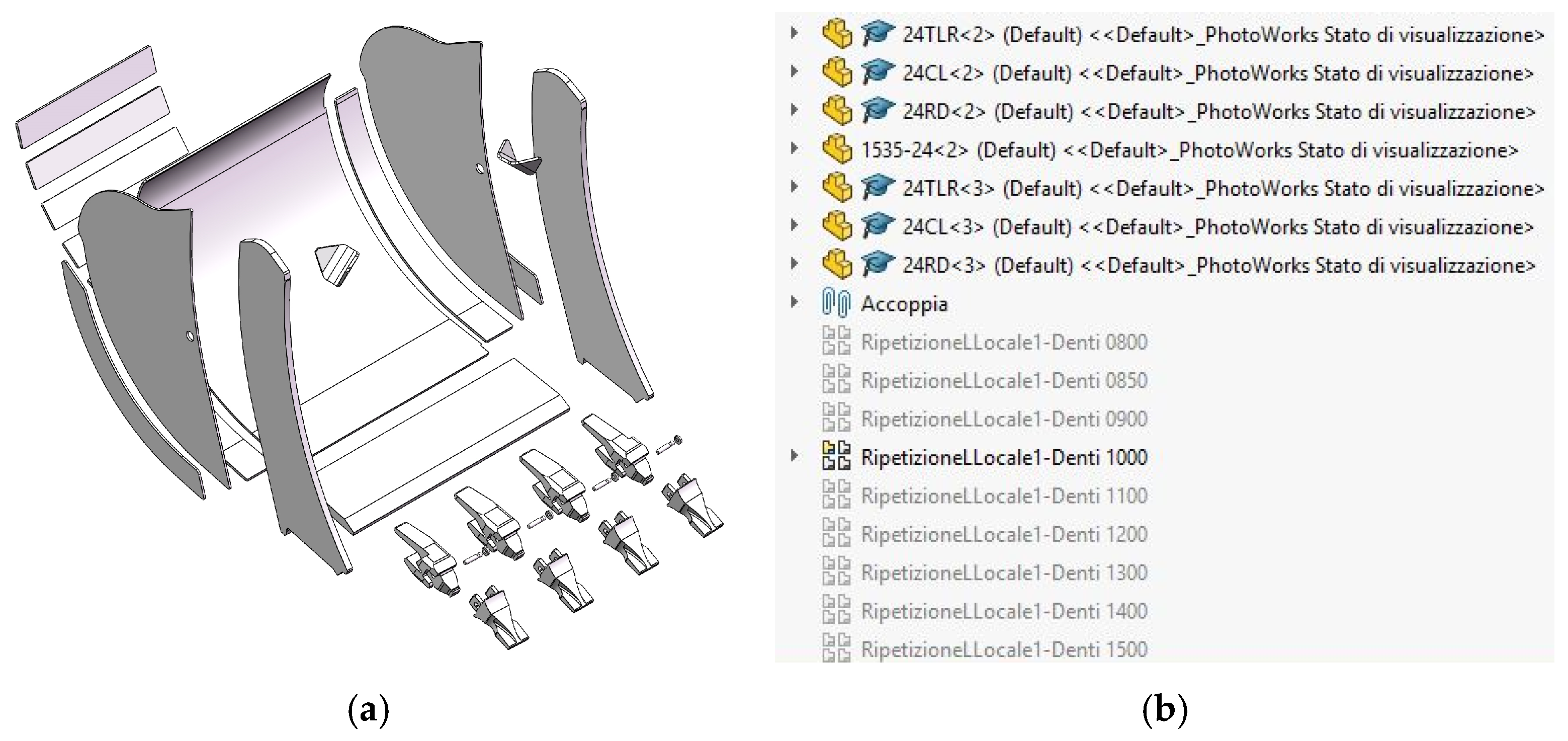
The number of teeth is different for different bucket configurations. Each tooth consists of several parts (Figure 10a). In the 3D model of the bucket, the parts are assembled and, using the Linear Component Pattern function, multiplied to the required number. For each configuration, the corresponding number of teeth is multiplied by the function. Depending on the configuration that is used, the corresponding geometric construction (Feature) is activated, while the others are suppressed using the Suppressed command (Figure 10b). In this case, parametric modeling is implemented by configuring a geometric construction (Feature) from the 3D model of the bucket.

Figure 10.
Configuration of teeth for a 1000 mm bucket: (a) Explode view of the 3D model of the base part; (b) tooth configuration.
There are different types of bucket teeth and, therefore, different sizes, for example, FK Fast Key, FS Orca S, FE Orca, Super V, CO CAT J, CAT K, KM Komatsu, VL Volvo, etc. [1,2,13,18]. If a bucket with a different tooth model has to be developed using the traditional modeling approach, a completely new 3D model of the bucket must be modeled too.
The following figure shows the tooth configuration (FK Fast Key) for a class D bucket, with a length of 1000 mm.
Figure 11 shows different lengths of the base part, parametrically modeled with configurations.
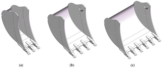
Figure 11.
Parametric models of the base part: (a) 500 mm; (b) 1000 mm; (c) 1500 mm.
3.2. Parametric Modeling of Upper Part
Figure 12 shows the algorithm used to design the upper part.

Figure 12.
Upper part design algorithm.
The 3D model of the upper part is parametrically modeled through configurations and Figure 13 shows its components.
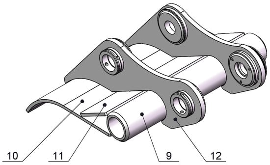
Figure 13.
Components of the upper part. 9—Tube, 10—Cover, 11—Rib, 12—Bucket Attachment.
Parts with positions 9, 10, and 11 are parametrically modeled and they have different length configurations. This sub-assembly also contains three parts that are structurally identical but differ in length. The Bucket Attachment 12 is the transitional link between the bucket and the excavator arm. The bucket attachment is different for different excavator models.
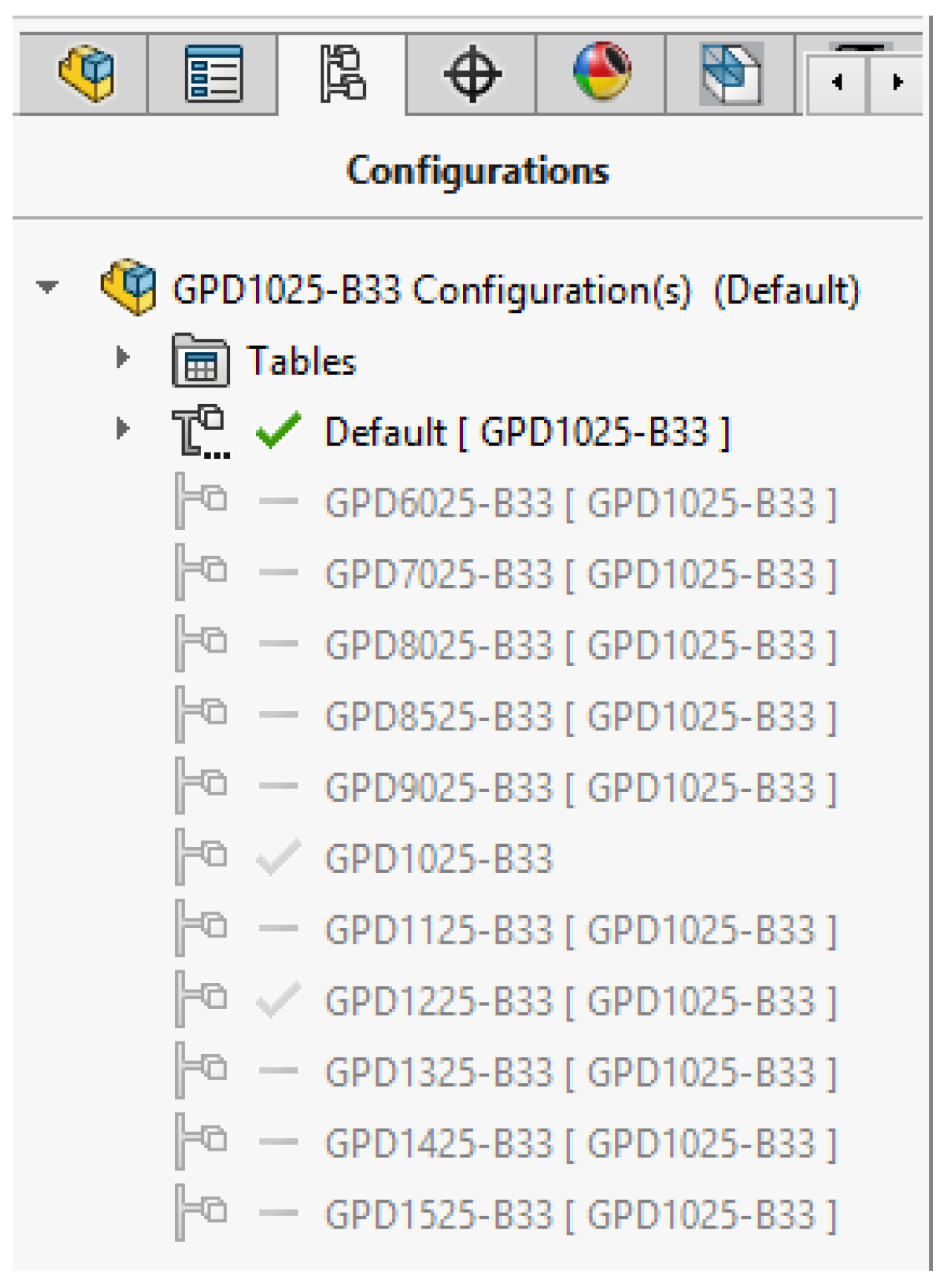
To model parametrically the 3D model of the upper part, configurations are created in the Configuration Manager (Figure 14). Each configuration represents a different length of the upper part. Upper parts differ in length—from 600 mm (GPD6025-B33) to 1500 mm (GPD1525-B33).
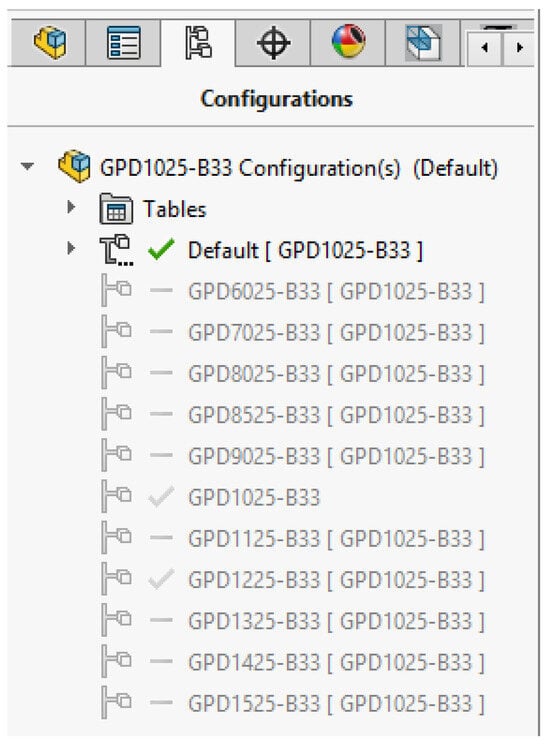
Figure 14.
Configurations in the 3D model of the upper part.
The next step is to configure the parts in the assembly of the upper part. Parts with positions 9 (Tube), 10 (Cover), and 11 (Rib) contain configurations with different lengths. For each configuration of the upper part, the corresponding configuration of the parts is set.
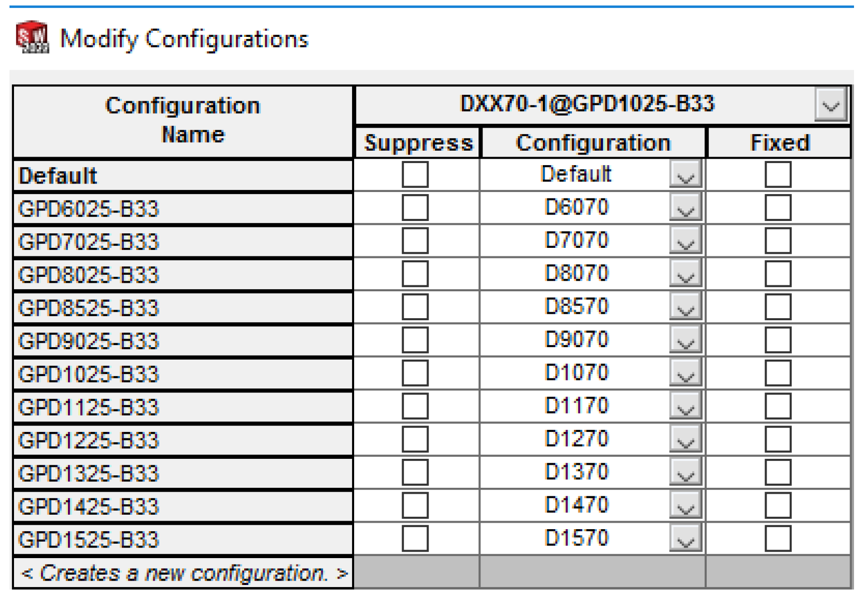
Figure 15 shows an example of the configurations of the upper part and the specified configurations of the tube part. For the corresponding lengths of the upper part, the tube part has the following configurations—from 600 mm (D6070) to 1500 mm (D1570).
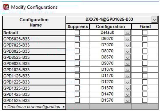
Figure 15.
Configuring the tube part.
A single 3D model of the tube part has been developed. Configuring the tube part involves setting different values for its length in the corresponding configuration (Table 3). Parametric modeling is implemented by configuring a dimension from the 3D model of the part.
Table 3.
Configurations of the tube part.
If the part is developed using the traditional modeling approach, a different 3D model of the tube part with the corresponding length must be modeled for each bucket model. In the case of class D buckets, 11 different 3D models of the part must be designed. Modeling multiple parts increases modeling time and the possibility of making errors.
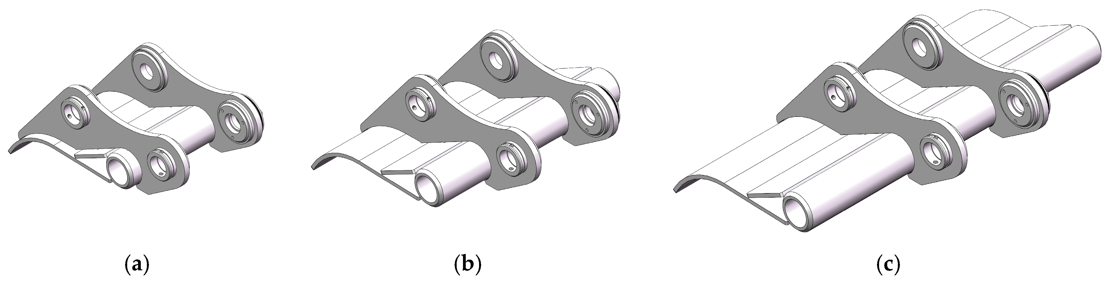
Figure 16 shows different lengths of the upper part, parametrically modeled with configurations.
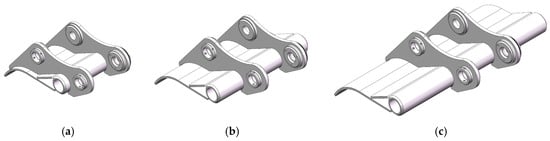
Figure 16.
Parametric models of the upper part: (a) 600 mm; (b) 1000 mm; (c) 1500 mm.
3.3. Parametric Modeling of Buckets
Figure 17 shows the algorithm used to design the bucket.
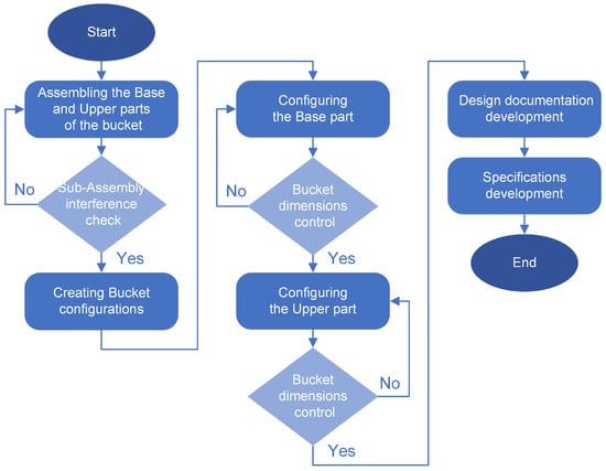
Figure 17.
Bucket design algorithm.
The 3D model of each bucket is parametrically modeled and has configurations with different lengths. The number of teeth is configured for each length. Depending on the model of excavator for which the respective bucket is designed, the bucket attachment is different, as well as the type and size of the teeth.
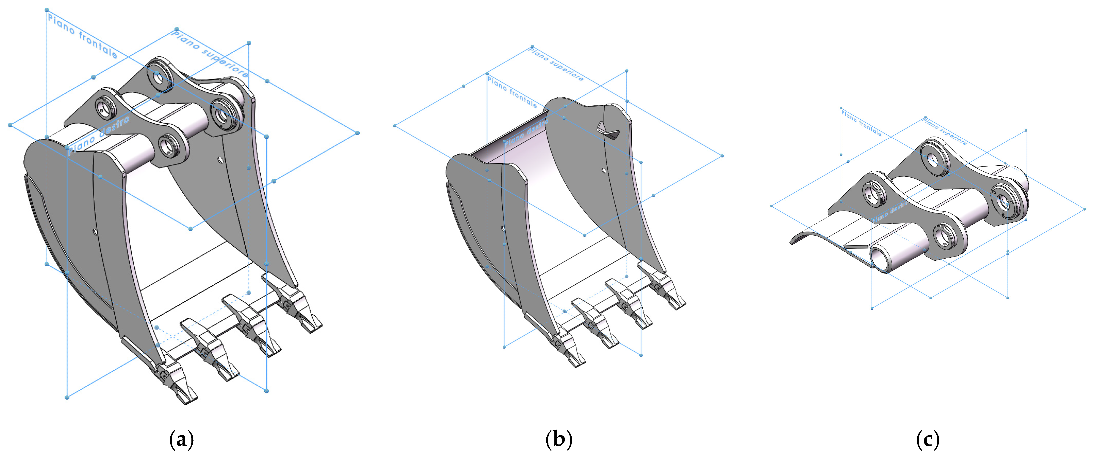
The 3D bucket model consists of the sub-assemblies—the base part and upper part are assembled using the main planes of the Assembly, i.e., Front Plane (Piano Frontale), Top Plane (Piano Superiore), and Right Plane (Piano Destro) (Figure 18).
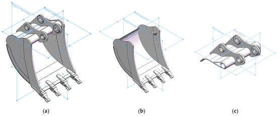
Figure 18.
Assembling the basic sub-assemblies of the 3D model of the bucket: (a) 3D model of the bucket; (b) base part; (c) upper part.
To perform assembly, the 3D models of the sub-assemblies have in the same place co-ordinate systems and planes that match with the co-ordinate system Origin and the base planes Front Plane, Top Plane, and Right Plane of the 3D model of the bucket. The 3D model that is assembled in this way allows quick replacement of the base or upper part with other similar ones through the function Replace Components. This allows automated generation of new 3D models of buckets, with different base parts or upper parts. For example, all special bucket designs shown in Figure 2 are modeled in this way.
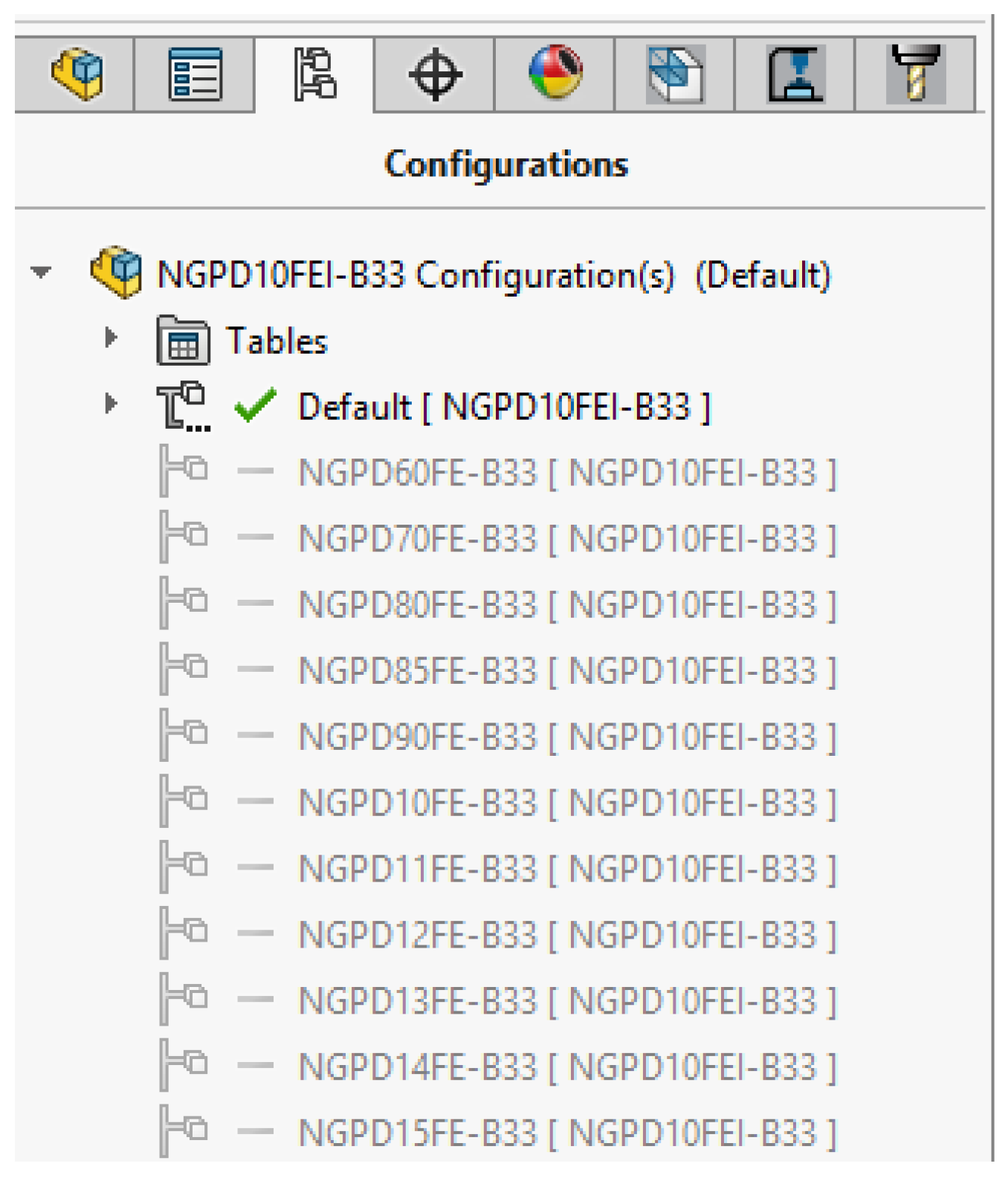
To model parametrically the 3D model of the bucket, configurations are created in the Configuration Manager (Figure 19). Each configuration represents a different length of the bucket. Buckets differ in length—from 600 mm (NGPD60FE-B33) to 1500 mm (NGPD15FE-B33).
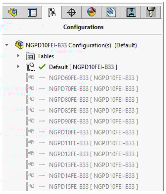
Figure 19.
Configurations in the 3D model of the bucket.
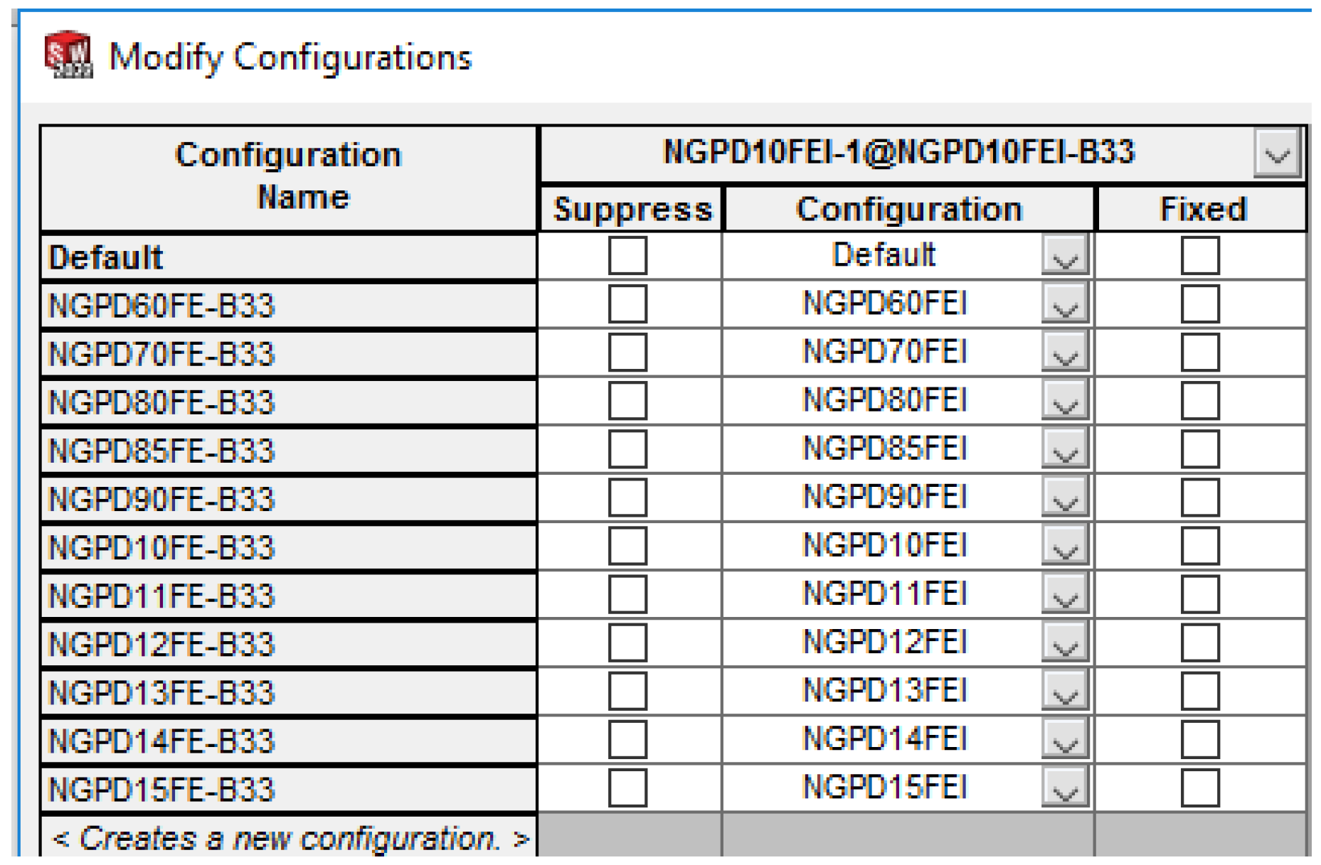
The next step is to configure the sub-assemblies in the assembly of the bucket. The base part and the upper part also contain configurations. For each bucket configuration, the corresponding configuration from the specific sub-assemblies is set. In this case, parametric modeling is implemented by configuring the sub-assemblies of the 3D model of the bucket.
Figure 20 and Figure 21 show examples of bucket configurations and configurations that are set for the base part and the upper part.
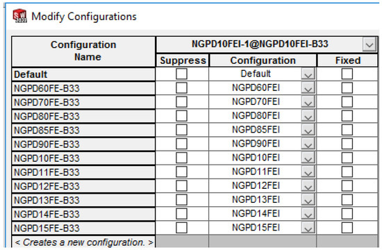
Figure 20.
Configuring the base part.
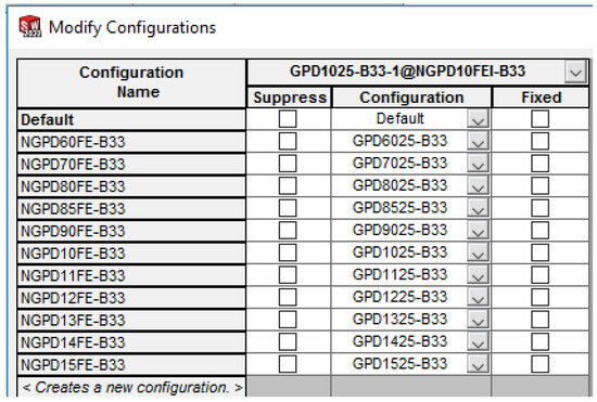
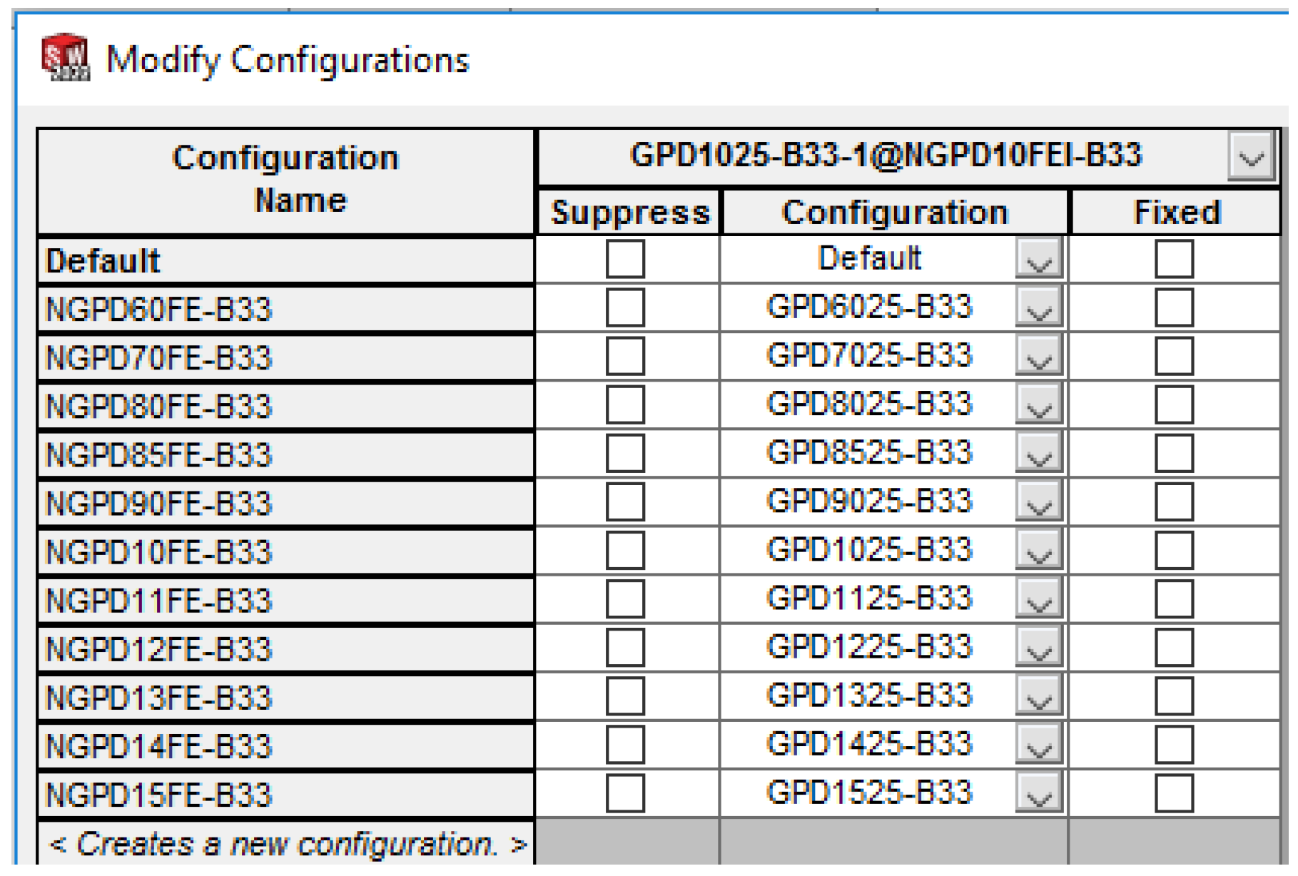
Figure 21.
Configuring the upper part.
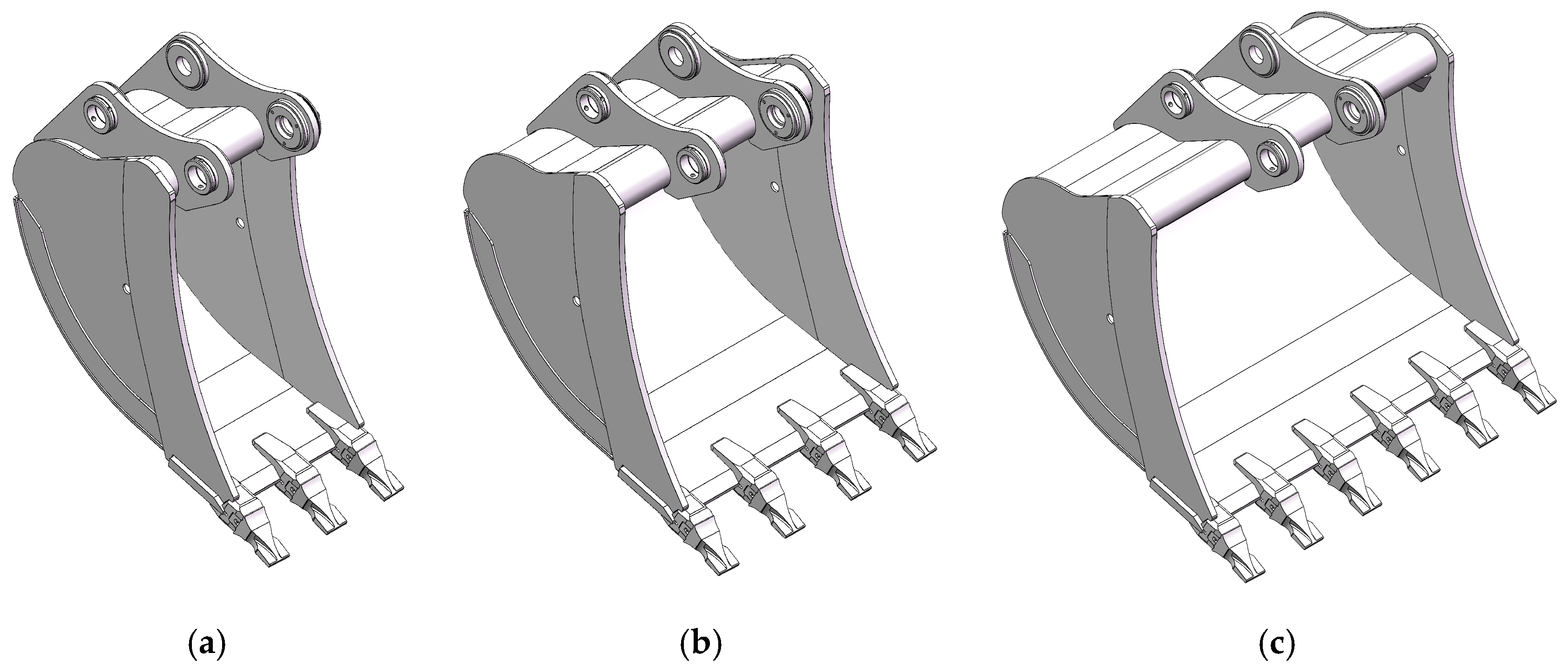
Figure 22 shows different bucket lengths parametrically modeled with configurations.
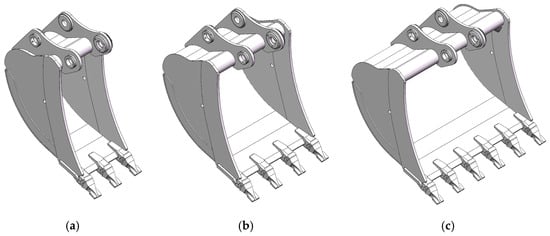
Figure 22.
Parametric models of the bucket: (a) 600 mm; (b) 1000 mm; (c) 1500 mm.
3.4. Design Documentation of the Buckets
Complete design documentation has been made for the developed excavator buckets. The process of its creation is automated by using document Template files in the SolidWorks CAD system.
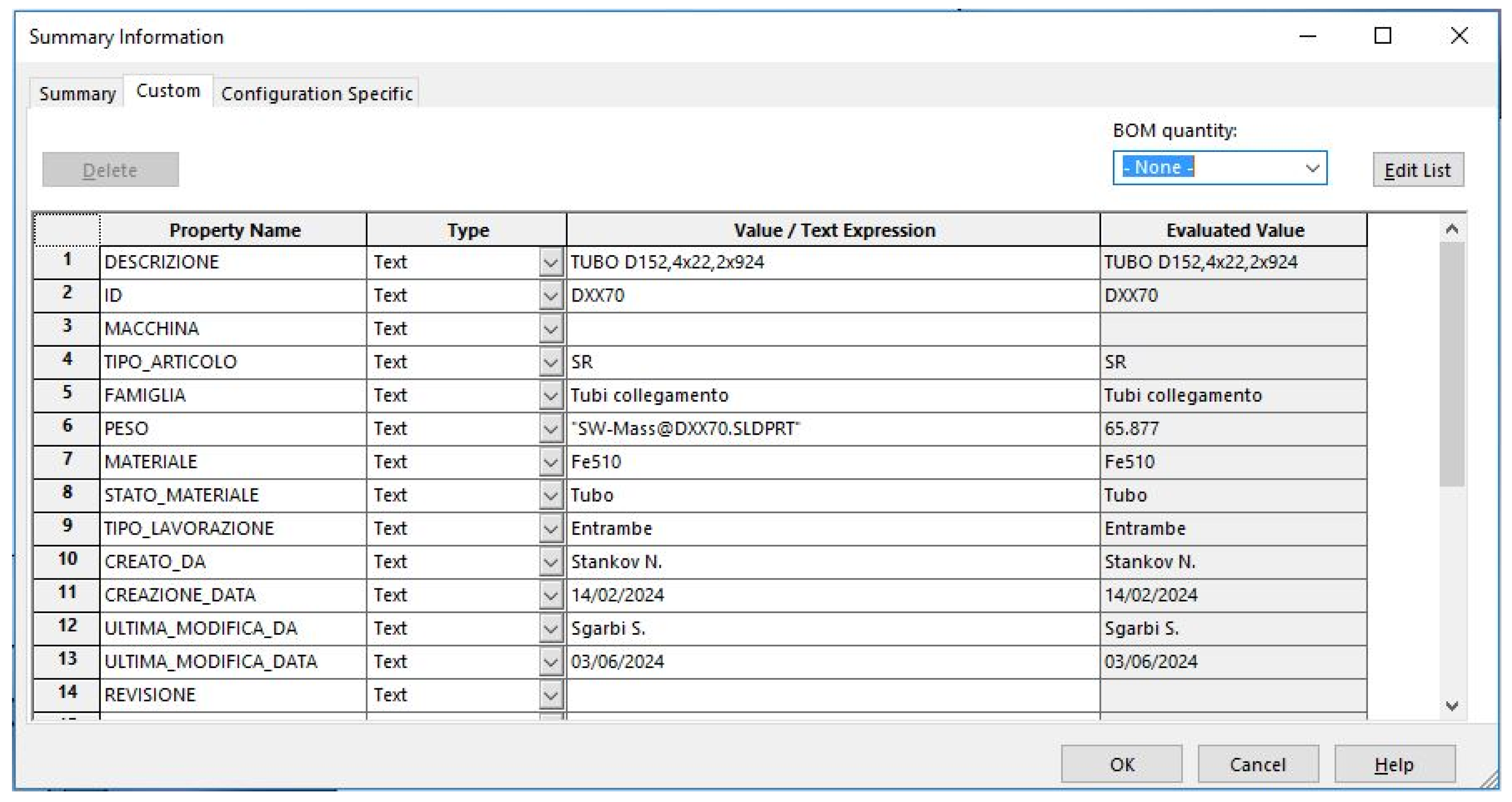
Template files for the Part and Assembly documents are used to create the 3D models of the parts and assemblies. In the template of each 3D model of the part or assembly, from the File Properties menu, in the Summary Information window, in the Custom section, the required attributes (users and systems ones) are selected. The attributes for each configuration are filled in the Configuration Specific window [5,6].
After the attributes of the 3D models have been filled in, the design documentation of the product (drawings and specifications) is prepared. For the considered example of an excavator bucket, drawings of all parts, the upper part sub-assembly, and the assembly of the bucket are developed.
For the development of the drawings, template files are used for the Drawing documents, which represent the standard drawing formats—A4, A3, A2, A1, and A0. Information from the attributes is automatically visualized in the drawing tables, in the assembly drawing specifications, and in individual product specifications [5,6].
Figure 23 shows examples of completed templates for the tube part and the sub-assembly of the upper part.
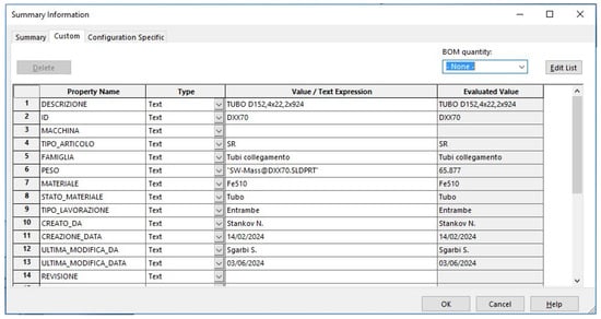
Figure 23.
Template of the tube part.
The following attributes are used in the template of each Part—Descrizione (name of the part), ID (drawing number), Macchina (assembly from which the part is taken), Peso (weight), Materiale (designation and type of the material from which it is made), Tipo Lavorazione (manufacturing operations), Creato Da (developed the document), Ultima Modifica Da (checked the document), Revisione (revision of the document), etc.
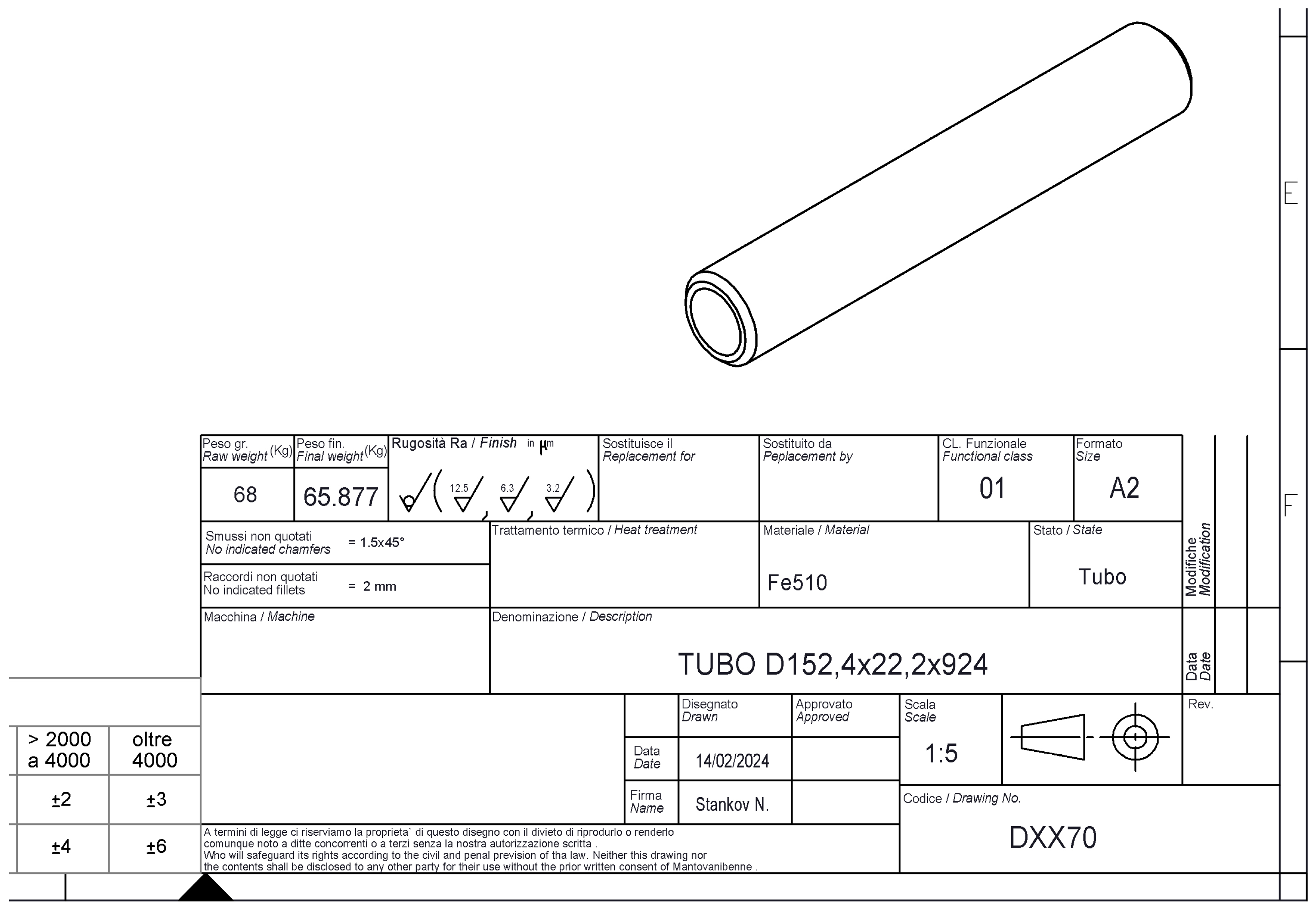
Figure 24 shows the drawing of a tube part, with an automatically filled table, based on the attributes specified in the 3D model of the part.
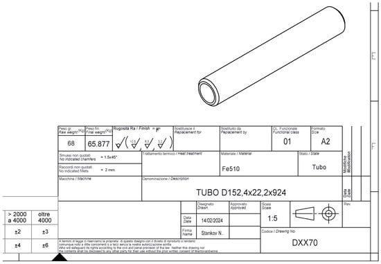
Figure 24.
Drawing of the tube part.
If this drawing is made using the traditional modeling approach, the drawing table should be filled in manually. Apparently, there would be errors as a result of repeated, identical actions by the designer.
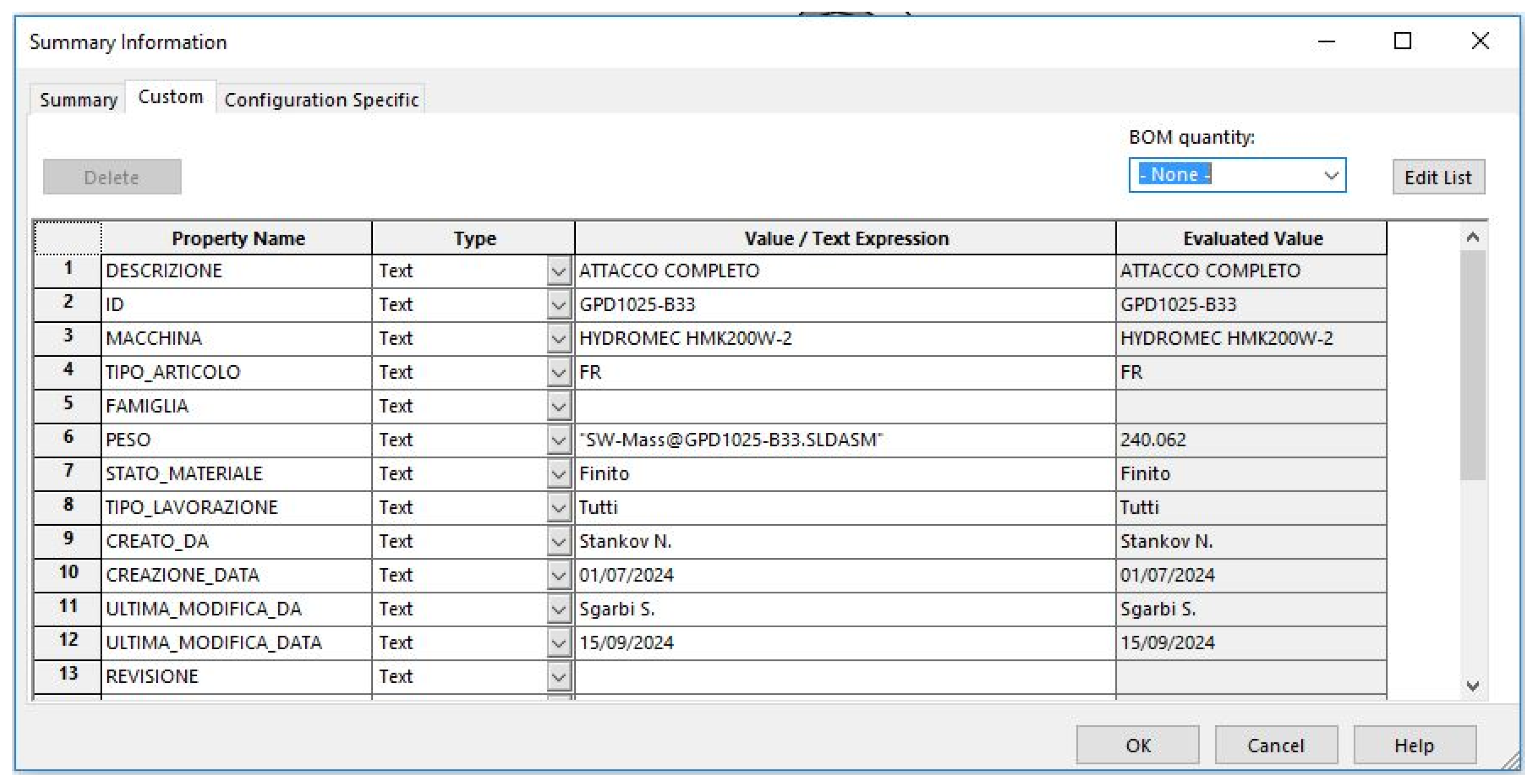
Figure 25 shows the attributes are used in the template of each Assembly—Descrizione (name of the assembly), ID (drawing number), Macchina (assembly on which the current assembly is based), Peso (weight), Tipo Lavorazione (manufacturing operations), Creato Da (developed the document), Ultima Modifica Da (checked the document), Revisione (revision of the document), etc.
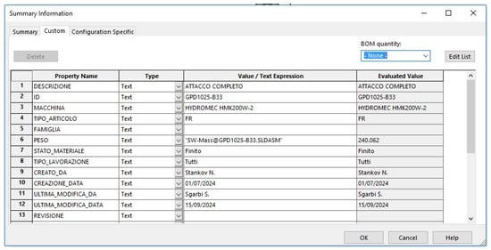
Figure 25.
Template of the upper part.
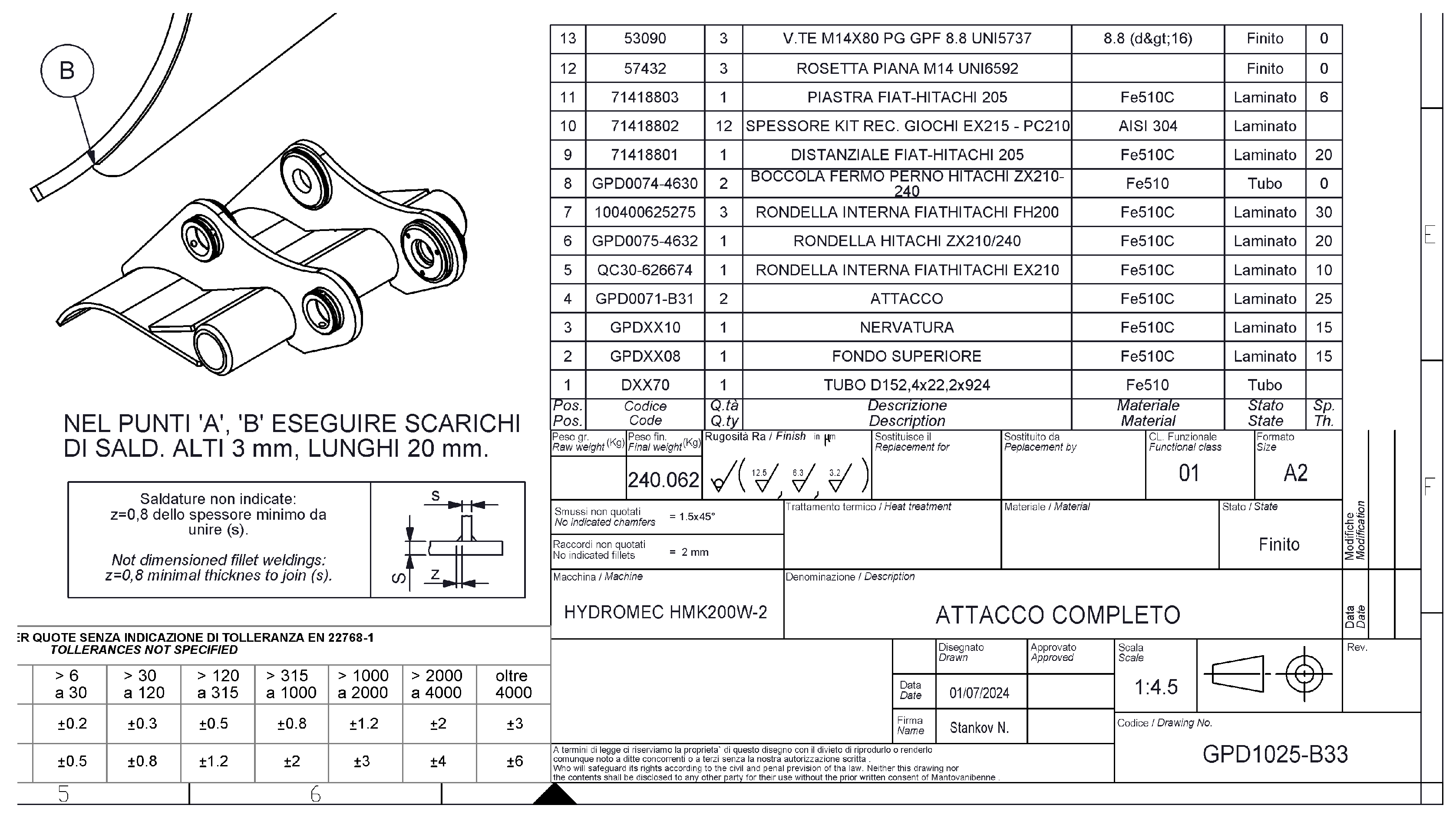
Figure 26 shows a drawing of the upper part, with an automatically filled table and specification, based on the attributes set in the 3D model of the assembly.
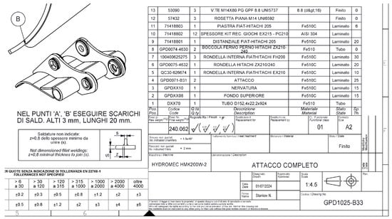
Figure 26.
Drawing of the upper part.
In the traditional modeling approach, the table on the drawing of the assembly is filled in manually. The specification is created in the drawing or made as a separate document and, again, filled in manually. Many mistakes are made and the time for creating increases significantly.
After the 3D models of the parts, sub-assemblies, assemblies, and all drawings of the buckets have been developed, the next step is their management by the specialized systems—PDM and ERP. The design documentation is managed by the PDM system SolidWorks PDM 2022 [3]. The various departments of the company have access to this information and operate with it through the ERP system RDS ERP [4].
In the PDM system, each configuration of the 3D model of a part or assembly is entered as a separate product. The system automatically fills in the fields on the Product Card based on the information set in the attributes of the part or the assembly for the corresponding configuration. If it is necessary in the product card, additional information can be added manually.
PDM systems are used when there is a big amount of design, technological, production, and other types of documentation accompanying the products that are developed, manufactured, and maintained. PDM systems solve the problems related to the maintenance, storage, and actuality of the large volume of documentation connected to the products [5,6].
4. Bucket Modeling Methods
A certain product can be designed by using traditional modeling or configurational parametric modeling. Both approaches are applied in practice.
The parametric modeling approach through configurations has been chosen because of the advantages it has. The reason for using this approach becomes clear after comparing the two modeling methods.
4.1. Traditional Bucket Modeling
In the traditional modeling approach, a 3D model is created for each bucket size. The 3D model of the bucket is an Assembly composed of parts and sub-assemblies. All parts are modeled in advance. Parts are structurally the same but differ in length, for different bucket models must be modeled as separate parts. In this bucket model, there are six parts. Some of the parts are the same for all buckets and they are modeled once. Depending on the bucket size, the number of these parts is different. For example, some buckets have four teeth but there are buckets that have fewer, more, or no teeth at all. After modeling the parts, they are assembled into the 3D model of the bucket. Table 4 shows a class D bucket and its components.
Table 4.
Classification of class D buckets, designed using the traditional modeling approach.
This approach has many disadvantages:
- -
- A large number of parts that must be modeled in advance;
- -
- A large number of assemblies to model;
- -
- Possible modeling errors due to the large variety of 3D models of parts and assemblies;
- -
- Creation of a big amount of design documentation—drawings of parts, drawings of assemblies, and specifications;
- -
- Redesigning the product when the size is different.
All these lead to a decreased efficiency of engineering work during design and an increased possibility of errors.
4.2. Parametric Bucket Modeling
In parametric modeling through configurations, a single 3D model of the bucket is modeled and it includes all its variations (Table 5). The 3D model of the bucket is composed of parts and sub-assemblies. All parts are modeled in advance. Parts that differ only in length are modeled parametrically through configurations. The parts are assembled into sub-assemblies, which are also modeled parametrically. The sub-assemblies are also assembled into the assembly of the bucket, which is also modeled parametrically.
Table 5.
Classification of class D buckets, designed using the parametric modeling approach.
Parametric modeling through configurations achieves high design efficiency. Design time is significantly reduced, as well as the possibility of making errors in modeling. The volume of design documentation accompanying the product is significantly reduced too. All this leads to an increase in the efficiency of engineering work when designing with CAD systems.
5. Research Methodology and Experimental Results
Several examples are considered to validate the proposed parametric modeling approach with configurations.
First, the traditional modeling approach will be considered. All parts and assembly of the class D buckets will be modeled. The time required to develop the 3D models will be calculated.
Second, the parametric modeling approach will be considered. The same parts and single assembly of the class D bucket will be modeled. The time required to develop them will be calculated.
All design time measurements were performed with the participation of engineers from the university R&D department working on real industrial projects. The projects are performed for external corporate clients. The measured values reflect the time required to design real products ordered by industrial partners who use the R&D department to design their products. This ensures that the results are representative of industrial conditions and validates the effectiveness of the proposed parametric methodology.
5.1. Traditional Modeling of Parts and Assemblies
The modeling of all the parts for the buckets, class D, will be considered. According to the information from Table 4, 29 unique parts and 6 parts need to be modeled for each 3D bucket model. These six parts differ only in length. The total number of parts that need to be modeled is 95 (Table 6).
Table 6.
Time for traditional modeling of all bucket parts.
The 3D models of all parts are modeled in advance. Therefore, in the column for a bucket, size 600 mm, the total time for modeling 29 unique parts is recorded, plus the time for modeling six parts, which are only for this bucket model. In the following columns, the time for modeling the six parts for the corresponding bucket model is recorded. The parts differ only in length.
The modeling of all buckets, class D, will be considered. According to the information in Table 4, 11 3D bucket models need to be modeled (Table 7).
Table 7.
Time for traditional modeling of all bucket assemblies.
First, the 3D model of a bucket, size 600 mm, is modeled. All parts are assembled in an Assembly file. The total time for the complete assembly of the bucket is recorded in the column. The following columns show the time needed for assembling only the six parts that differ in length. The following 3D models of the buckets are created from the base model 600 mm, replacing only the six different parts. The Replace Components function is used. This allows automated generation of new 3D models.
5.2. Parametric Modeling of Parts and Assemblies
The modeling of all the parts for the buckets, class D, will be considered. According to the information from Table 5, 29 unique parts and 6 parts that differ only in length need to be modeled. These six parts will be modeled as a single 3D model with configurations for the corresponding lengths. The total number of parts that need to be modeled is only 35 (Table 8).
Table 8.
Time for parametric modeling of all bucket parts.
The modeling of all buckets, class D, will be considered. According to the information from Table 5, only one 3D bucket model will be modeled (Table 9).
Table 9.
Time for parametric modeling of all bucket assemblies.
In parametric modeling, a single 3D model of a bucket is modeled, with configurations for the different lengths. All parts are assembled in an assembly file. For the corresponding bucket configurations, the six parts, which are of different lengths, are configured.
5.3. Errors Occurring in the Modeling
When modeling parts and assemblies with CAD systems, errors of various kinds may occur. Such errors can be:
- -
- Errors in determining the dimensions during the process of designing the parts;
- -
- Errors in 3D modeling of parts;
- -
- Errors in assembling the parts into the bucket assemblies;
- -
- Errors when creating configurations of parts and assemblies;
- -
- Errors in configuring parts and sub-assemblies in assemblies of the buckets;
- -
- Errors when filling in the Template files of the 3D models of the parts and the assemblies;
- -
- Errors when creating drawings of parts and assemblies;
- -
- Errors when filling in the drawing tables;
- -
- Errors when creating and filling in specifications.
In Table 10, the summarized errors in the designing and modeling of excavator buckets are given, using the two approaches—traditional modeling and parametric modeling.
Table 10.
Bucket modeling errors.
5.4. Research Results
According to the obtained results for the modeling of the parts and assemblies of the buckets, the following conclusions can be made:
- -
- In traditional modeling, the total number of parts and buckets that need to be modeled is bigger—95 parts and 11 buckets, compared to 35 parts and 1 bucket in parametric modeling;
- -
- In traditional modeling, the average time for modeling the total number of parts and buckets is longer—65 h for parts and 22 h for buckets, compared to 34 h for parts and 10 h for buckets in parametric modeling;
- -
- In traditional modeling, the average number of errors that occur is higher—22, compared to 6 in parametric modeling;
- -
- Parametric modeling significantly increases the efficiency of engineering work—the volume of design documentation created is reduced and the time required for modeling products is reduced;
- -
- As a result of the smaller amount of design documentation, the number of errors in product modeling is significantly reduced;
- -
- Reducing design time is especially important in modern working conditions, where engineering departments consist of only a few people;
- -
- Parametric modeling is an approach that should be used for products with many variants and variations, as is the case with the considered excavator buckets.
6. Application of the Parametric Modeling Approach
The presented parametric modeling approach is applied in the development of various products, which demonstrates its functionality and versatility. The following figures will present examples of products developed using the parametric modeling method through configurations.
For each of the examples, a single 3D model has been developed. In the assembly of the product, the parts and sub-assemblies are parametrically modeled with configurations.
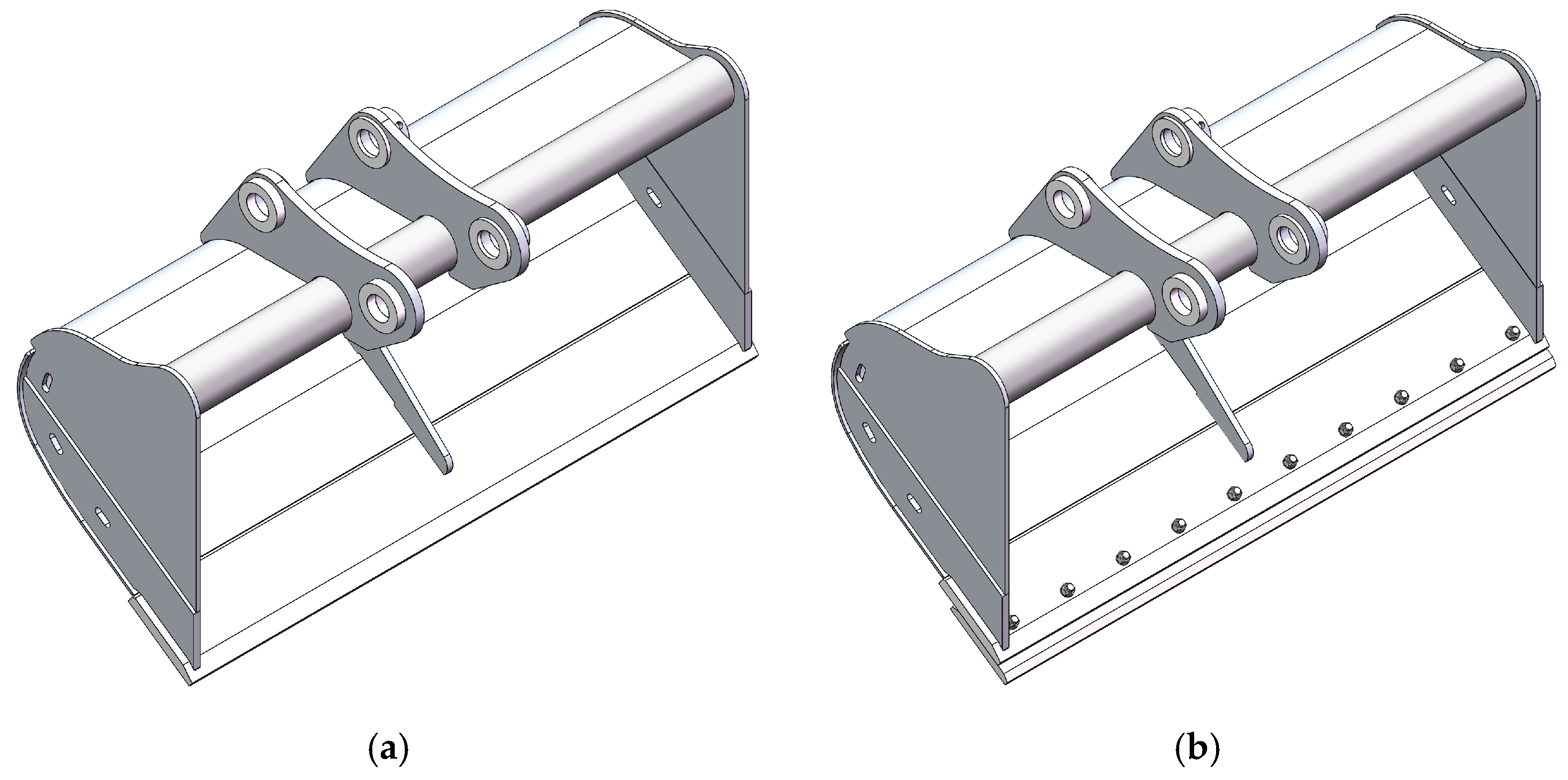
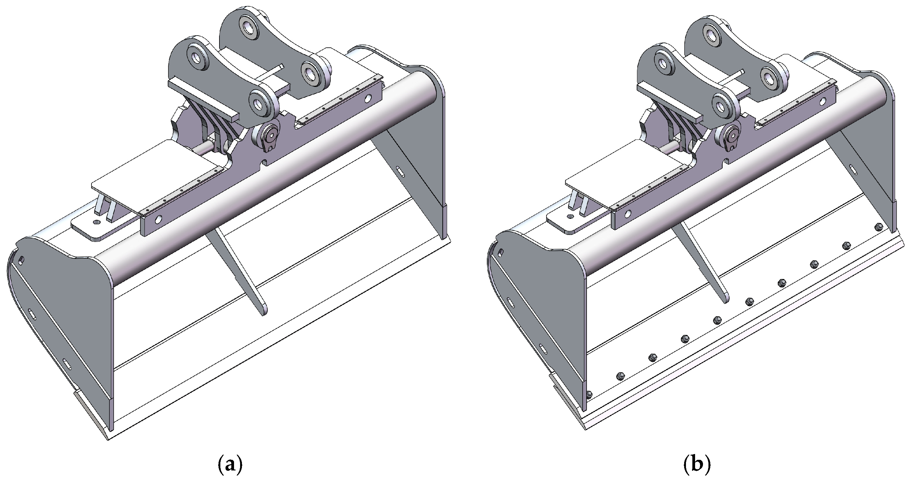
Figure 27 and Figure 28 show cleaning buckets [1,2]. They are parametrically modeled with configurations. The buckets vary in length—from 1600 mm to 2400 mm. Each configuration represents a different bucket length.
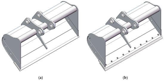
Figure 27.
Parametric models of cleaning buckets for straight terrain, class D: (a) 2000 mm; (b) 2000 mm, with additional blade.
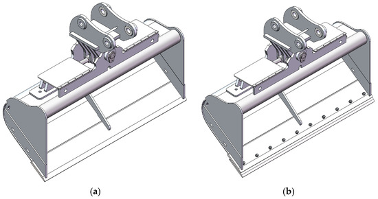
Figure 28.
Parametric models of cleaning buckets for sloping terrain, class D: (a) 2000 mm; (b) 2000 mm, with additional blade.
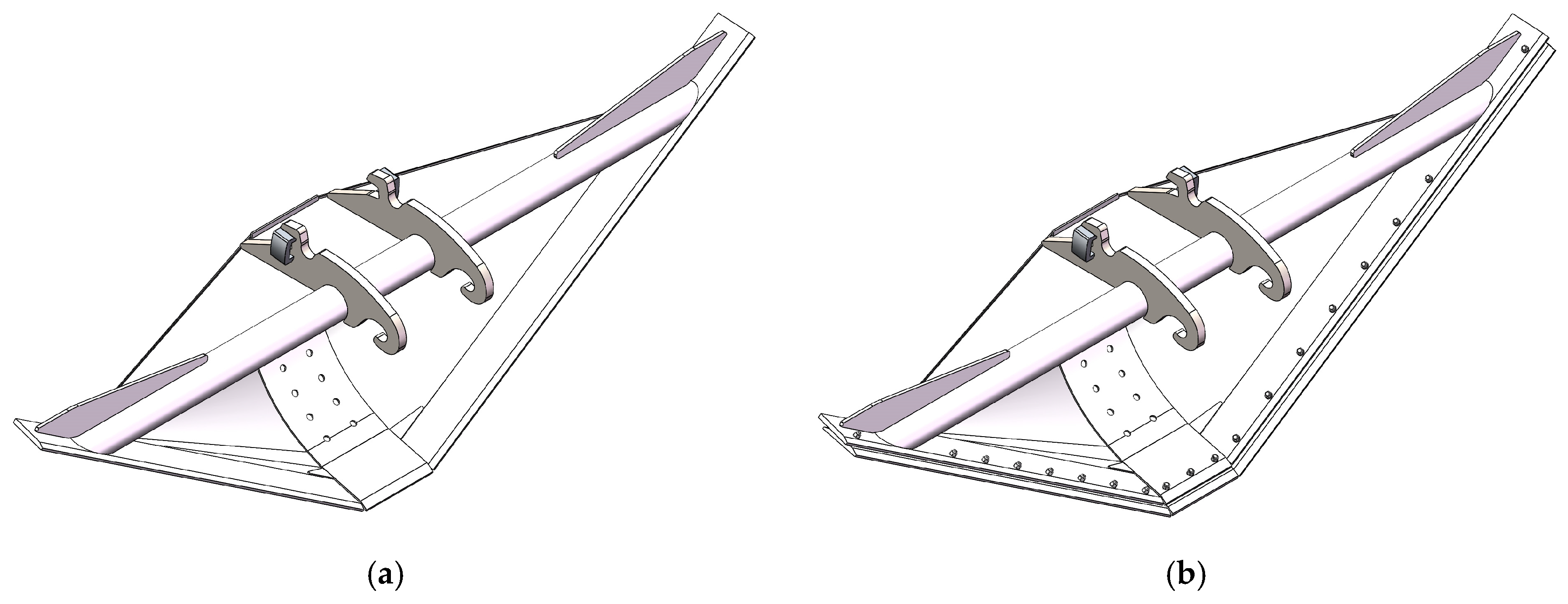
Figure 29 shows trapezoidal buckets [1,2]. They are parametrically modeled with configurations. The buckets vary in length—from 2500 mm to 5000 mm. Each configuration represents a different bucket length.

Figure 29.
Trapezoidal buckets: (a) 5000 mm; (b) 5000 mm, with additional blades.
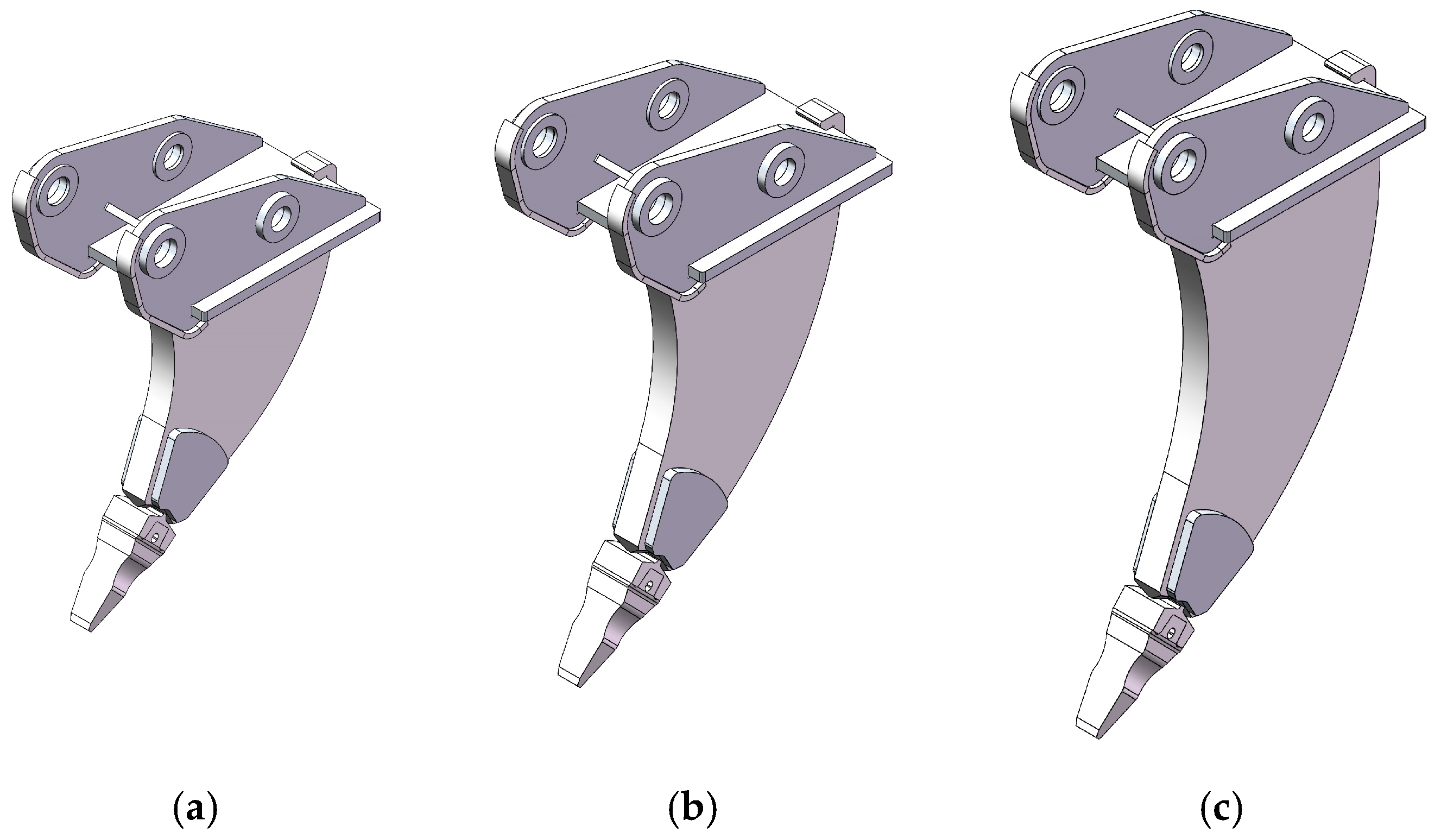
Figure 30 shows the scarifier tooth [1,2]. It is parametrically modeled with configurations. The products differ in length. Each configuration represents a different length of the scarifier tooth.

Figure 30.
Scarifier tooth (ripper): (a) 950 mm; (b) 1150 mm; (c) 1350 mm.
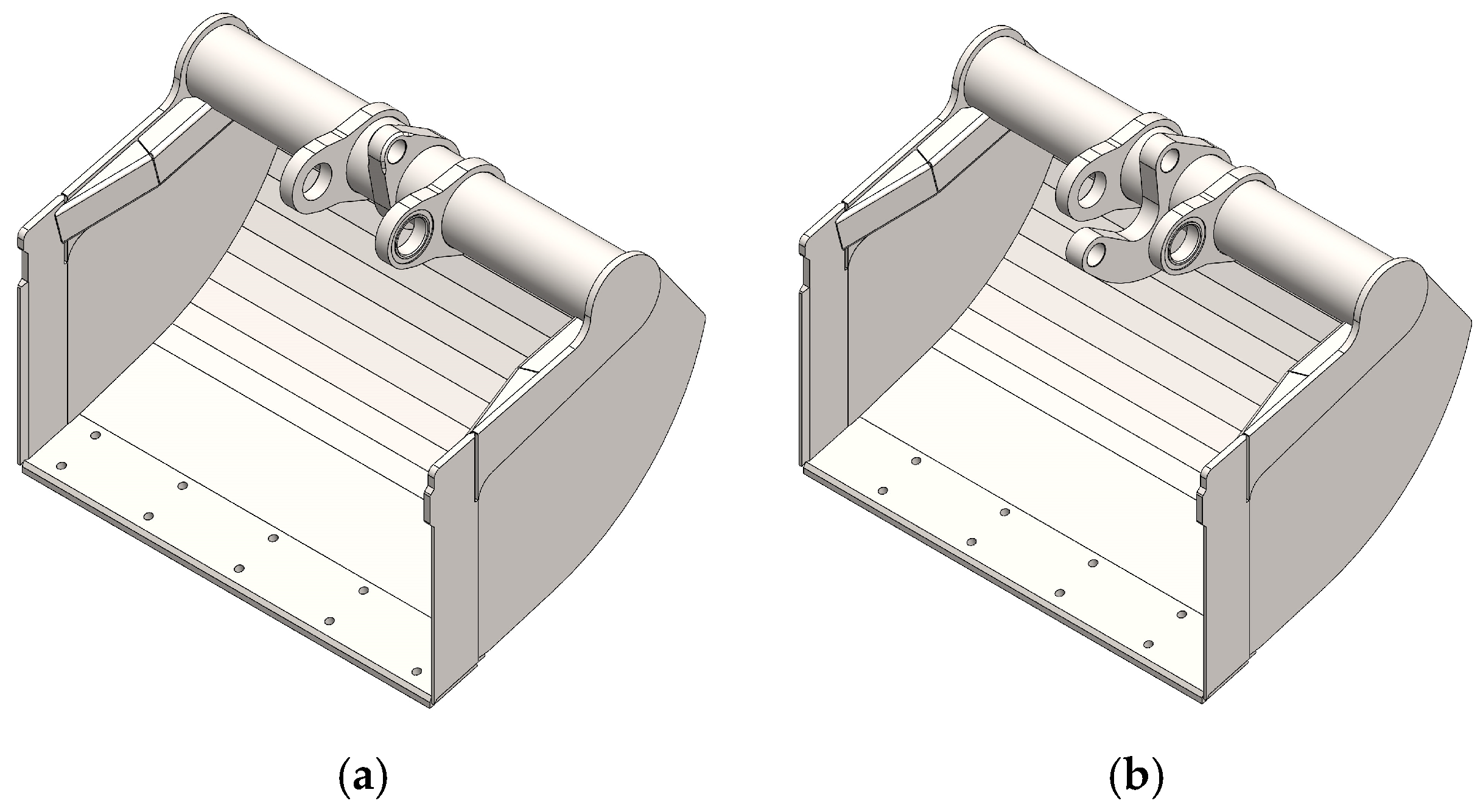
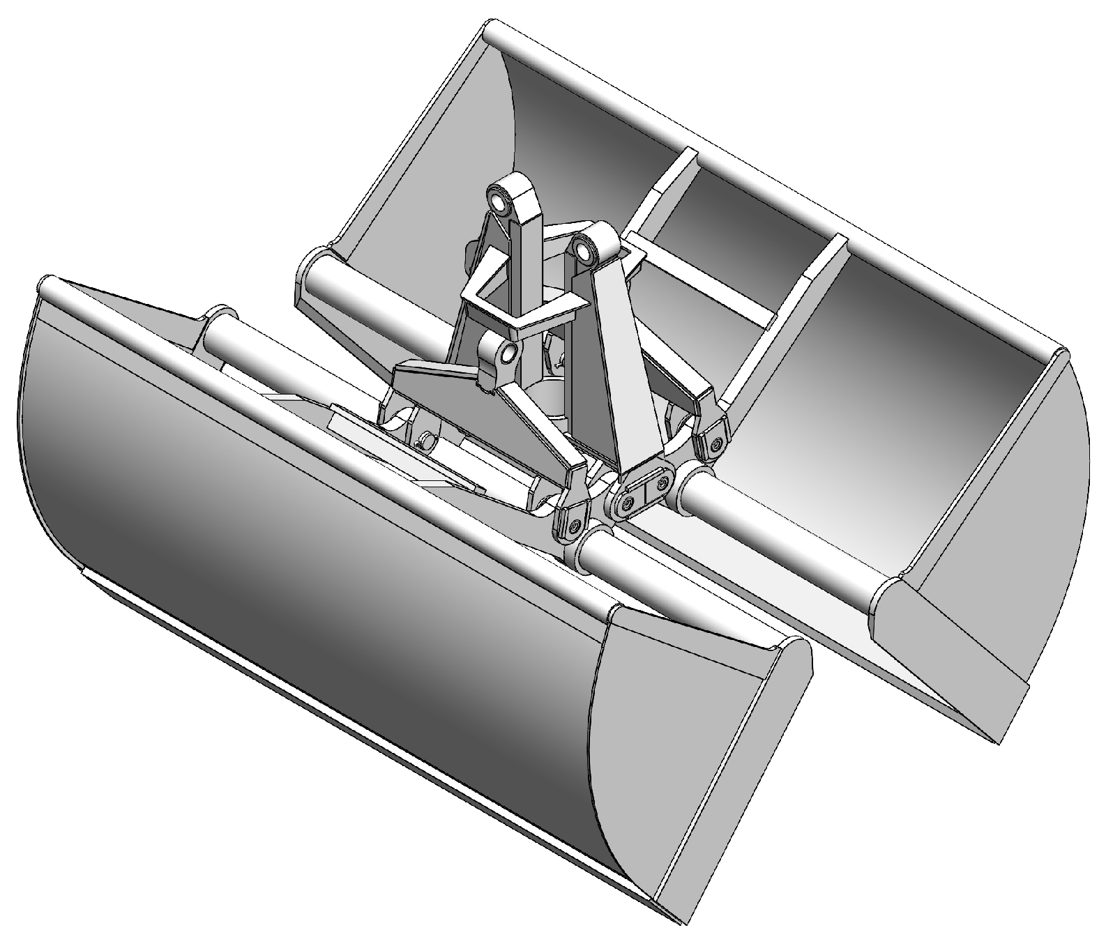
The following figures show grapple buckets, developed again using the proposed method for parametric modeling by configurations [26,27,28]. The grapple bucket consists of left and right buckets, which are manufactured as a set (Figure 31).
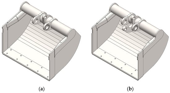
Figure 31.
Components of the grapple bucket, 1000 mm: (a) left bucket; (b) right bucket.
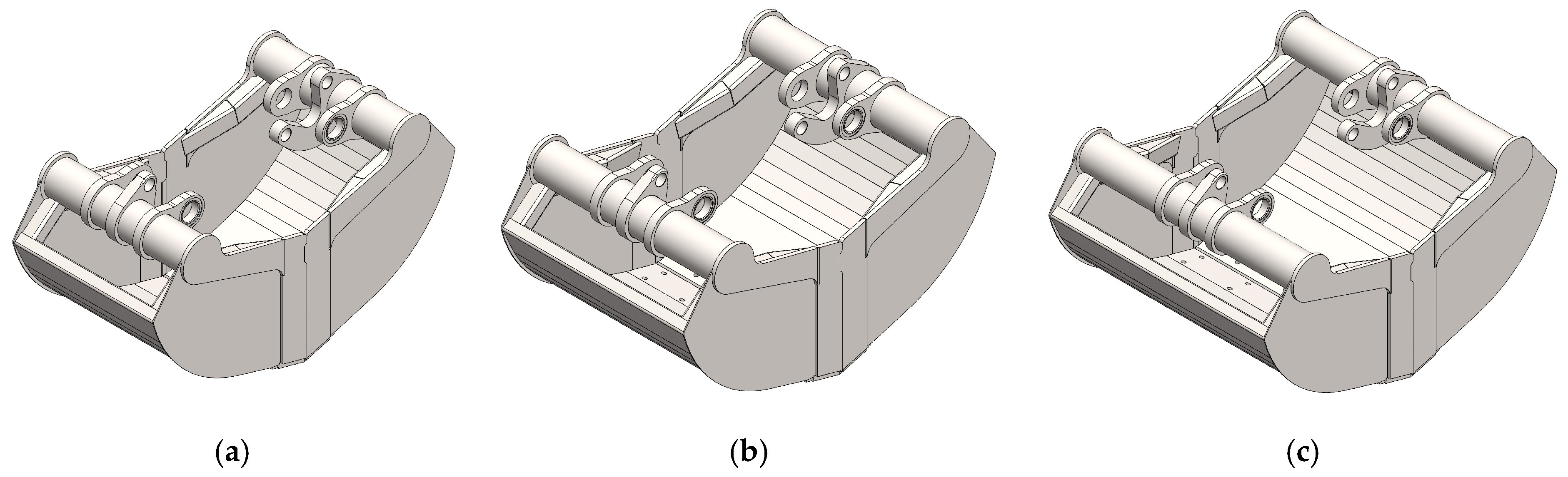
Figure 32 shows the 3D model of the bucket, which is parametrically modeled. The buckets differ in length, respectively—600 mm, 800 mm, and 1000 mm.
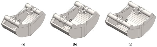
Figure 32.
Parametric grapple bucket models: (a) 600 mm; (b) 800 mm; (c) 1000 mm.
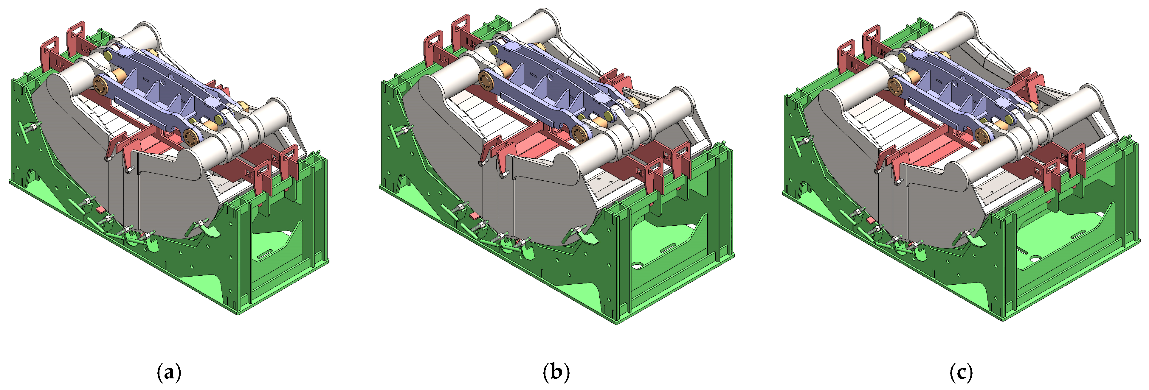
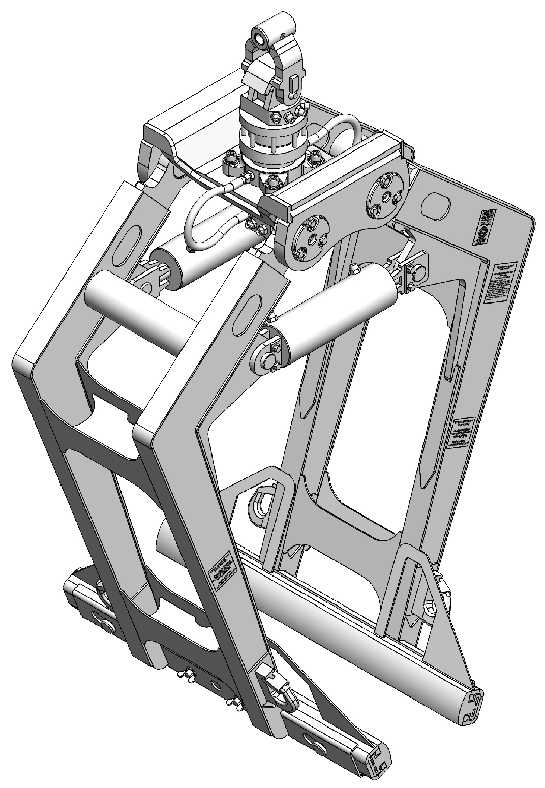
The grapple buckets have a complex shape and construction. For the manufacture of the left and right grapple buckets in a set, specially designed fixtures are used. The fixture is used to base the parts and sub-assemblies of the buckets in a specific position with precisely defined distances between them. Figure 33 shows the designed fixture for assembling the grapple buckets, which is also parametrically modeled.

Figure 33.
Parametric models of the grapple bucket manufacturing fixture: (a) 600 mm; (b) 800 mm; (c) 1000 mm.
Figure 34, Figure 35, Figure 36, Figure 37 and Figure 38 show other examples designed using the parametric modeling approach.

Figure 34.
Parametric model of a grapple for bulk materials, 400 mm.
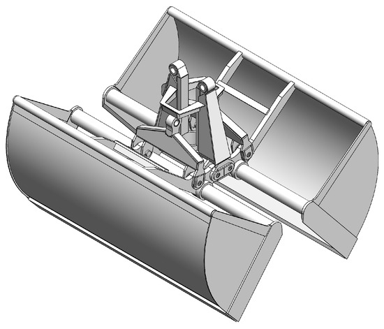
Figure 35.
Parametric model of a grapple for bulk materials, 2600 mm.
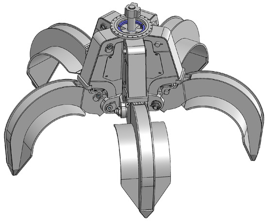
Figure 36.
Parametric model of a sorting grapple.

Figure 37.
Parametric model of a pallet grabber.

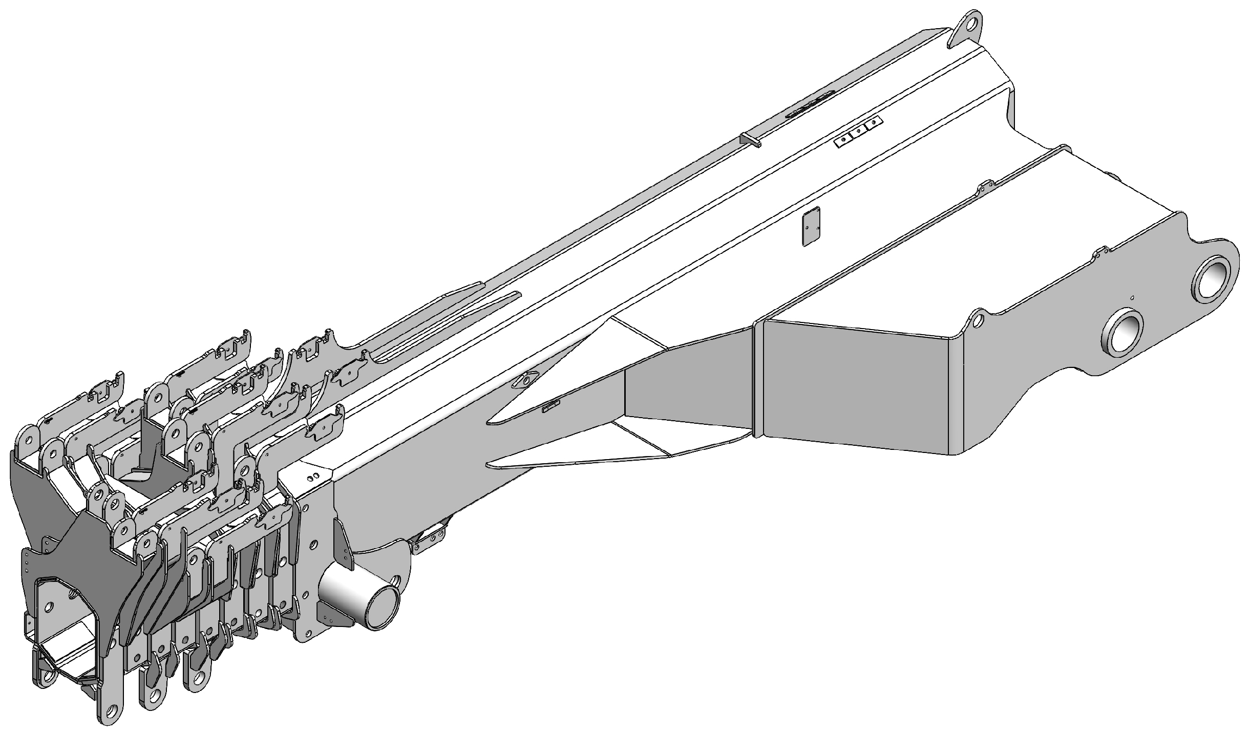
Figure 38.
Parametric model of a set of crane booms.
The proposed method for parametric modeling through configurations has been successfully validated in real engineering projects, not only in the design of excavator buckets but also in the development of other complex products, such as excavator and crane grapples, crane booms, and hydraulic demolition hammers. All these applications are related to the construction and heavy engineering industries, where parametric modeling provides rapid adaptation of structural elements to different sizes, loads, and installation requirements. In the case of grapples, parametric modeling allows for rapid generation of variants with different sizes of jaws (buckets) and drive mechanisms. In the case of crane booms, parametric modeling provides various boom sizes in the set for the crane. In the case of hydraulic hammers, optimization through configurations ensures compatibility with different excavator models and working loads.
All the products presented in the publication have a complex shape and structure. Specialized fixtures are used to manufacture them. The parametric modeling approach can be used to develop not only products but also specialized fixtures. According to the methodology, only one 3D model of the fixture is developed, which is parametrically modeled using configurations. In the same way, fixtures for assembling, welding, mechanical processing, functional testing, or product control are designed and modeled.
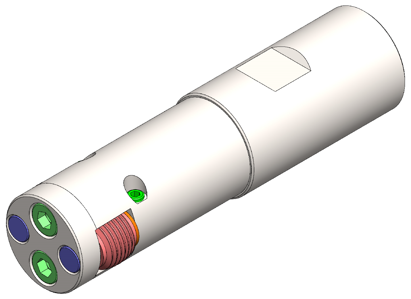
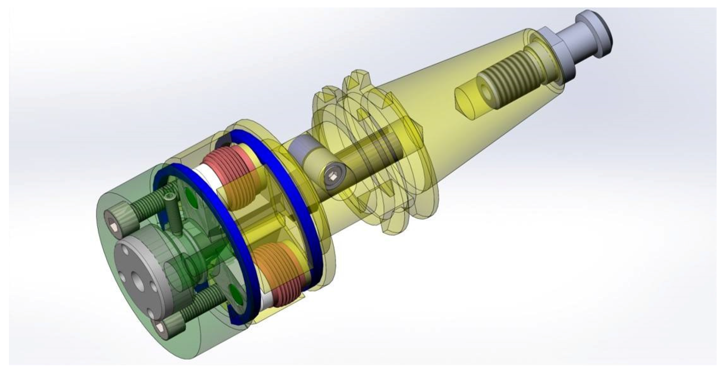
Figure 39, Figure 40 and Figure 41 show examples of metalworking tools developed using the parametric modeling approach through configurations.

Figure 39.
Parametric model of a thread rolling head for internal threads for M30.
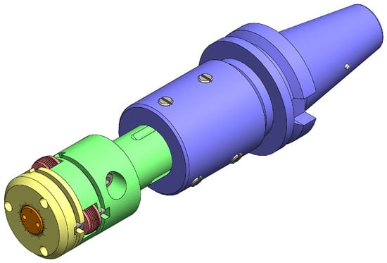
Figure 40.
Parametric model of an adjustable thread rolling head.
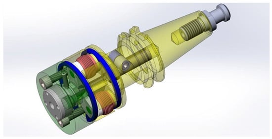
Figure 41.
Parametric model of a thread rolling head with automatic retraction of the rolling rolls.
Another place where this methodology finds direct application is the design of metalworking tools. Tools such as thread cutting heads and thread rolling heads have been modeled. The tools consist of a cutting part and shank. According to the specific machine, the shank of the tool is designed through parametric modeling, which ensures its reliable and effective fastening. In this type of product, the main challenge is to provide a standardized but, at the same time, flexible connection between the cutting part of the tool and its shank. The shank is attached to the machine through different holders, each of them has its own standard sizes and design features. Through parametric modeling, configurations can be created that allow the tool to be quickly adapted to different machines, without the need to design the model again. This significantly facilitates the design process and allows the implementation of one tool in different production environments.
The practical implementation of the method in co-operation with industrial partners demonstrates its applicability in various manufacturing sectors and confirms its potential for optimization of engineering processes. In addition, integration with PDM and ERP systems allows effective management of project data and version traceability, which facilitates co-ordination between the different stages of design and production. This not only improves the accuracy of engineering documentation but also reduces the time to implement new products in series production.
7. Discussion
This article presents a methodology for automated design and parametric modeling of excavator buckets, implemented with CAD system SolidWorks 2022 The methodology covers all stages of product design—modeling of 3D models of parts, creating assemblies, and generating design documentation. The article highlights the advantages of this type of parametric design as well as improving work efficiency.
All modern CAD systems offer mechanisms for parametric modeling and configuration, although they have different names and different approaches to implementation. For example, in SolidWorks 2022, this is called “Configurations” [3]; in PTC Creo 11, it is “Family Tables” [29]; in CATIA V6 R2024, it is “Design Tables” [30]; in Autodesk Inventor 2024, it uses “iParts/iAssemblies”, automated by iLogic [31]; and Siemens NX 2406 has “Part Families” and “Product Configurations”, combined with User-Defined Attributes (UDA) [32]. The methodology considered in this study is not specific to only one CAD system but is applicable to different CAD software. This makes it possible to adapt our approach to different industrial environments, without being limited to the use of only one specific software. Future research could conduct a more in-depth analysis of the performance of these different CAD platforms in industrial applications.
One of the main outcomes from the application of this type of parametric modeling is the significant reduction in the volume of design documentation, as well as the reduction in the complexity of the work performed. Traditional design requires a manual creation of numerous design variations, while the automated generation of different bucket configurations requires minimal human interaction.
The comparison between traditional and parametric modeling through configurations clearly demonstrates a significant advantage in productivity when using configurations. The use of parametric modeling and configurations leads to a significant reduction in the number of necessary 3D models and drawings, which results in 50% time savings in modeling through configurations. Automating the creation of documentation leads to a significant reduction in errors and improves the accuracy of the design. This is especially true for companies where rapid design preparation is required to meet the specific customer requirements.
The proposed methodology has been tested with professional engineers working on real industrial projects commissioned by external companies. They use parametric modeling with configurations within standard industrial processes, which ensures that the measured time and efficiency reflect real operating conditions. Although this study focused on a specific industry area, further testing in different sectors would be beneficial. Future research could extend the evaluation by collecting feedback on the applicability of the method from engineers working in different manufacturing environments, which would allow a wider analysis of its adaptability and effectiveness.
The proposed approach to modeling through configurations has been successfully applied by the R&D Centre at the University of Ruse (Bulgaria) on projects for several different clients. The goal is to increase the efficiency of engineering processes and reduce design time. Engineering departments usually consist of several people and the time required to design and model a specific product should be minimal. Design work is a crucial stage in the product manufacturing process. In real production, the time from receipt of an order for a specific product to its actual production is very short. In this case, the engineering tasks involve more than just developing 3D models and design documentation. It is necessary to know the entire technological process for the product production. The development of 3D models must be consistent with the specific technology for manufacturing the product. The examples of the excavator buckets and all products described in the publication have been manufactured and are actively used in practice. The approach discussed is only part of the entire process of developing a specific product, focusing only on the final 3D modeling and preparation of documentation.
Integrating CAD models with Product Data Management (PDM) and Enterprise Resource Planning (ERP) systems improves the options for data management. By structuring product data within a centralized system, the revision and control processes can be managed effectively. This integration not only optimizes the collaboration between Engineering and Production departments but also improves traceability and adherence to industry standards.
The results of this study are consistent with the existing scientific literature on parametric modeling and its applications in engineering design. Previous studies have highlighted the benefits of automation created by CAD systems to reduce development time cycles and improve product quality. The present methodology builds on these principles, demonstrating their practical application in the design of excavator buckets.
However, although the proposed methodology significantly increases design efficiency, there are also certain limitations. The initial setup and configuration of parametric models require specialized knowledge and thorough understanding of the functionalities of the CAD software. In addition, the effectiveness of the automated design process depends on the stability of the predefined parameters and constraints. It might be exciting to see if we can use AI to optimize the parameterization even more and obtain some better design solutions.
While AI-based modeling has significant potential in engineering design, its direct integration into regulated industrial environments poses a number of challenges, especially related to compliance with regulatory requirements such as the Machinery Directive 2006/42/EC. Current AI solutions are oriented towards optimization according to various criteria such as efficiency. However, we have not found publications that AI solutions have mechanisms for automated compliance with industry standards, traceability of engineering changes, and certification processes. Furthermore, automatically generated AI designs may not pass the necessary regulatory validation for industrial use. These factors make the direct integration of AI into parametric engineering workflows challenging and require additional research. Of particular interest would be the area of AI-based compliance checking and automated regulatory validation.
Any modern publication related to CAD modeling should also address the role of artificial intelligence. Despite the potential of generative AI models in engineering design, their direct integration into the product design process has some significant limitations and challenges. This is especially valid if the designed products are aimed at the EU and other related markets.
Main challenges with using generative AI models in product design:
- -
- Generative AI models create shapes and designs based on optimization algorithms but do not guarantee compliance with industry standards (e.g., ISO, ASME, or the Machinery Directive 2006/42/EC). This creates risks of an invalid product that does not meet the necessary safety, durability, or manufacturability requirements.
- -
- Generative AI models, especially those based on neural networks, often function as a “black box”—it is difficult to understand why the system has made a certain decision. This leads to problems with the traceability of engineering decisions (a key requirement in the Machinery Directive and quality management standards), especially in highly regulated industries such as automotive, aviation, construction tools and equipment, or medical equipment. It is easy to reach a case of a product failure, where it will be difficult to trace which parameter or which logic in the AI led to the defective design.
- -
- CAD systems are designed to work with traditional geometric and parametric models, not with the organic shapes generated by AI. The present AI can create 3D models (STL, STEP, and IGES) that cannot be directly opened in SolidWorks or other 3D CAD systems without additional manual processing [33].
- -
- Generative AI has no engineering intuition or experience, which are often key to making decisions in complex situations. An engineer can predict future work scenarios that AI cannot take into account if they are not included in its training data.
When the safety of machines/devices/equipment directly depends on them being designed using a Large Language Model (LLM), then there will be regulatory implications under the Machinery Directive and its new extended cyber requirements. Here are some scenarios:
- -
- If an error made in the LLM design leads to potential safety risks (e.g., incorrect tolerances, noncompliance with safety standards, unsuitable materials, or incorrect calculations), then control and compliance are required.
- -
- The Machine Directive requires traceability of software changes to designs, and LLM is dynamic and generates code/designs that may be difficult to verify. Validation and certification of the results of each design stage may be required to ensure that LLM does not create risks.
- -
- If the LLM has an impact on the safety of machinery, it is very likely that additional certification or additional inspections will be required (e.g., according to ISO 12100 [7] and IEC 61508 [34]).
- -
- If LLM generates safety code or CAD models that are critical to the safety of the products, validation and testing will need to be provided.
In summary, when LLM is a critical part of the design of machinery, it will require severe additional verifications and compliance with the Machinery Directive. Depending on the use, it may also fall under the new cybersecurity requirements.
Where does AI have potential?
Despite limitations, generative AI technologies have potential as follows:
- -
- For conceptual design—to quickly generate innovative ideas that can be further developed by engineers.
- -
- When optimizing specific parameters—for example, when reducing the weight of parts or minimizing material costs.
- -
- For engineering analysis—discovering correlation dependencies between parameters in complex structures.
In conclusion, this study demonstrates that effective parametric modeling optimizes engineering processes. It reduces design time, minimizes errors, and improves documentation management, supporting the development of digital engineering methodologies. Although the development does not address this issue, the authors believe that the methodology can be applied in other areas of machine design, supporting efficiency and innovation in industrial design.
8. Conclusions
An approach for designing specialized products using a CAD system is presented. The implementation of parametric modeling through the SolidWorks CAD system allows significant automation in the design of excavator buckets. The use of configurations facilitates the creation of various product variants, reducing the time and volume of manually created documentation.
The presented approach is applicable to other similar products, which emphasizes its universal nature. In this way, similar problems related to the development and management of documents can be solved.
The presented bucket design approach provides a possibility for creating a bucket with a new size or a custom bucket design from an existing class within minutes.
Using the parametric modeling approach with configurations, specialized fixtures for manufacturing can be developed. These include fixtures for assembling, welding, mechanical processing, functional testing, product control, etc.
Parametric modeling through configurations is used in various areas of industry where machines, equipment, and structures are designed. The presented methodology is used to model products with multiple variations, sizes, and versions.
The use of attributes (user and systems ones) in the 3D models of parts and assemblies enables the automated preparation of design documentation (drawings of parts and assemblies and specifications).
The proposed approach of modeling through configurations improves the efficiency of engineering work by reducing design time, the volume of design documentation, and errors during product design.
The presented integration between the 3D models and PDM system allows effective management of a large volume of design documentation. Automatic synchronization of attributes in models and the system leads to better traceability, variation, and accessibility of data for all departments in the company, including departments such as Supplies and Production. The files can also be used by other company departments through the ERP system. This is an innovative approach to the digitalization of engineering processes.
The use of specialized CAM software to create machining programs significantly increases the accuracy and efficiency in bucket production. The inclusion of 3D models for direct preparation of production documentation demonstrates the modernization of traditional production methods, while facilitating the implementation of technological improvements.
Although the present study demonstrates the advantages of parametric modeling in the automation of the design process for excavator buckets and other similar products, the potential of this approach can be extended in several directions.
One possible future direction is the integration of the proposed methodology with the concept of Digital Twins. The parametric models that have been developed can be used as a basis for building virtual representations of the products, which can be updated in real time with operational data. This would allow tracking of wear and load on structures, as well as optimization of future designs based on real operating conditions.
Another important aspect is the potential use of artificial intelligence for automatic generation and optimization of parametric models. AI-based algorithms could suggest optimal design solutions based on analysis of previous designs and operational data. Future research could explore the interaction between parametric modeling and AI to improve the flexibility and efficiency of the design process. Changes in regulations in major global markets regarding AI will lead to additional challenges for the use of AI in the design of industrial products.
The main challenge in using generative AI models in product design for highly regulated industries (automotive, aerospace, construction tools and equipment, medical devices, etc.) is the lack of ability for control, traceability, and compliance with market regulations and industry standards. While these systems can be a powerful tool for the conceptual phase of designing or optimizing specific aspects, they are not yet able to replace human engineering judgment and strictly regulated engineering processes.
Author Contributions
Conceptualization, N.S. and A.I.; methodology, N.S. and A.I.; software, N.S.; validation, N.S. and A.I.; formal analysis, N.S.; investigation, N.S.; resources, N.S.; data curation, N.S. and A.I.; writing—original draft preparation, N.S.; writing—review and editing, N.S. and A.I.; visualization, N.S.; supervision, N.S.; project administration, N.S.; funding acquisition, N.S. and A.I. All authors have read and agreed to the published version of the manuscript.
Funding
This study is financed by the European Union—NextGenerationEU, through the National Recovery and Resilience Plan of the Republic of Bulgaria, project No. BG-RRP-2.013-0001.
Institutional Review Board Statement
Not applicable.
Informed Consent Statement
Informed consent was obtained from all subjects involved in the study.
Data Availability Statement
The raw data supporting the conclusions of this article will be made available by the authors on request.
Conflicts of Interest
The authors declare no conflicts of interest.
References
- Buckets Line. 2025. Available online: https://mantovanibenne.com/en/attachments/buckets/ (accessed on 12 March 2025).
- Buckets Line. 2025. Available online: https://www.mbibulgaria.bg/ (accessed on 12 March 2025).
- SolidWorks, 3D Design Software. SolidWorks CAM, CAM Software. SolidWorks PDM, PDM Software. 2025. Available online: https://www.solidworks.com/ (accessed on 12 March 2025).
- RDS ERP, ERP Software. 2025. Available online: https://www.smeup.com (accessed on 12 March 2025).
- Stankov, N.; Ivanov, A. Design Documentation Management with SolidWorks Enterprise PDM. Collection of Scientific Works; University of Ruse: Ruse, Bulgaria, 2015; Volume 54, Series 2; pp. 158–165. ISSN 1311-3321. [Google Scholar]
- Truhcheva, D.; Stankov, N.; Ivanov, A. Management and Organization of Design Documentation with SolidWorks and SolidWorks Enterprise PDM. Collection of Reports of a Student Scientific Session–SSS’15; University of Ruse: Ruse, Bulgaria, 2015; pp. 20–30. ISSN 1311-3321. [Google Scholar]
- ISO 12100:2010; Safety of Machinery—General Principles for Design—Risk Assessment and Risk Reduction. International Organization for Standardization: Geneva, Switzerland, 2010.
- Autodesk Inventor. 3D Design Software. 2025. Available online: https://www.autodesk.com/ (accessed on 12 March 2025).
- Solid Edge. 3D Design Software. 2025. Available online: https://solidedge.siemens.com/en/ (accessed on 12 March 2025).
- Creo. 3D Design Software. 2025. Available online: https://www.ptc.com/en (accessed on 12 March 2025).
- CATIA. 3D Design Software. 2025. Available online: https://www.3ds.com/products/catia (accessed on 12 March 2025).
- Altair Inspire. 3D Design Software. 2025. Available online: https://altair.com/inspire (accessed on 12 March 2025).
- Stankov, N. Design of Excavator Buckets with the SolidWorks CAD System. Collection of Reports of a Student Scientific Session–SSS’10; University of Ruse: Ruse, Bulgaria, 2010; pp. 16–21. ISSN 1311-3321. [Google Scholar]
- Pecingina, O. Modelling bucket excavation by finite element. IOP Conf. Series: Mater. Sci. Eng. 2015, 95, 012046. [Google Scholar] [CrossRef]
- Vîlceanu, F.; Iancu, C. Bucket wheel rehabilitation of ERC 1400-30/7 high-capacity excavators from lignite quarries. IOP Conf. Series Mater. Sci. Eng. 2016, 161, 012081. [Google Scholar] [CrossRef]
- Bošnjak, S.; Arsić, M.; Gnjatović, N.; Milenović, I.; Arsić, D. Failure of the bucket wheel excavator buckets. Eng. Fail. Anal. 2018, 84, 247–261. [Google Scholar] [CrossRef]
- Ren, Z.; Sun, H.; Liang, Y.; He, Y.; Feng, M. Strength analysis of excavator bucket based on normal digging trajectory and limiting digging force. J. Vibroengineering 2020, 23, 217–226. [Google Scholar] [CrossRef]
- Suryo, S.H.; Sastra, R.S.; Muchammad, H. Optimization of bucket tooth excavator design using topology optimization and finite element method. J. Physics Conf. Ser. 2021, 1858, 012081. [Google Scholar] [CrossRef]
- Hepa, M. Design and Optimization of Lightweight and HSD Excavator Bucket with Uncertain Load. Int. J. Curr. Eng. Technol. 2021, 11, 222–226. [Google Scholar] [CrossRef]
- Sun, Y.; Wang, Y.; Wang, L.; Li, C.; Tang, L.; Wang, D.; Ma, R.; Xue, Z.; Wei, X.; Cui, M.; et al. Digging Performance and Stress Characteristic of the Excavator Bucket. Appl. Sci. 2023, 13, 11507. [Google Scholar] [CrossRef]
- Wang, Y.; Wang, L.; Li, C.; Xue, Z.; Sun, Y.; Ma, R.; Wang, D.; Cui, M.; Wei, X.; Tang, L.; et al. Optimization of Excavator Bucket Structure by a Coupled Simulation Method. Appl. Sci. 2023, 13, 11336. [Google Scholar] [CrossRef]
- Liu, G.; Han, X.; Wang, Z.; Wang, K.; Zhang, Z.; Duan, Z. Viscosity Reduction and Drag Reduction Performance Analysis of Bionic Excavator Buckets Based on Discrete Element Method. Biomimetics 2024, 9, 686. [Google Scholar] [CrossRef] [PubMed]
- Abebe, M.; Cho, Y.; Han, S.C.; Koo, B. Mitigating Measurement Inaccuracies in Digital Twins of Construction Machinery through Multi-Objective Optimization. Sensors 2024, 24, 3347. [Google Scholar] [CrossRef] [PubMed]
- Liu, C.; Li, Y.; Jiang, X.; Shao, W. Five-axis flank milling tool path generation with curvature continuity and smooth cutting force for pockets. Chin. J. Aeronaut. 2020, 33, 730–739. [Google Scholar] [CrossRef]
- Wang, Y.; Wang, D.; Zhang, S.; Tang, Z.; Wang, L.; Liu, Y. Design and development of a five-axis machine tool with high accuracy, stiffness and efficiency for aero-engine casing manufacturing. Chin. J. Aeronaut. 2022, 35, 485–496. [Google Scholar] [CrossRef]
- High Volume Clamshell Buckets. 2025. Available online: https://www.kinshofer.com/en/crane/general-construction/high-volume-clamshell-buckets (accessed on 12 March 2025).
- SL Industries. 2025. Available online: https://sl-industries.com/ (accessed on 12 March 2025).
- Bullitt Engineering. 2025. Available online: https://bullitt-engineering.com/ (accessed on 12 March 2025).
- Family Tables. 2025. Available online: https://support.ptc.com/help/creo/creo_pma/r11.0/usascii/index.html#page/fundamentals/fundamentals/About_Family_Tables_1.html (accessed on 12 March 2025).
- Managing CATIA V5 Design Tables. 2025. Available online: https://support.ptc.com/help/windchill/plus/r12.0.2.0/en/index.html#page/Windchill_Help_Center/WGMCATIAV5AdvTechFamTable.html (accessed on 12 March 2025).
- iPart and iAssembly Functions Reference (iLogic). 2025. Available online: https://help.autodesk.com/view/INVNTOR/2025/ENU/?guid=GUID-4BA100AA-B55A-4A08-AD8F-79AA27771C7E (accessed on 12 March 2025).
- Managing NX Part Families. 2025. Available online: https://support.ptc.com/help/windchill/plus/r12.1.2.0/en/index.html#page/Windchill_Help_Center/WWGMforNX/WWGMNXAdvTechNXManagePartFams.html (accessed on 12 March 2025).
- Kozov, V.; Ivanov, A.; Ivanova, G. Research Result Differences Between Manual Research and Using AI LLMs for Analyzing Popular 3D File Formats. TEM J. 2024, 13, 2637–2658. [Google Scholar] [CrossRef]
- Iec 61508; Safety and Functional Safety. Available online: https://www.iec.ch/functional-safety (accessed on 12 March 2025).


Disclaimer/Publisher’s Note: The statements, opinions and data contained in all publications are solely those of the individual author(s) and contributor(s) and not of MDPI and/or the editor(s). MDPI and/or the editor(s) disclaim responsibility for any injury to people or property resulting from any ideas, methods, instructions or products referred to in the content. |
© 2025 by the authors. Licensee MDPI, Basel, Switzerland. This article is an open access article distributed under the terms and conditions of the Creative Commons Attribution (CC BY) license (https://creativecommons.org/licenses/by/4.0/).