Abstract
Wrist kinematics can provide insight into the development of repetitive strain injuries, which is important particularly in workplace environments. The emergence of markerless motion capture is beginning to revolutionize kinematic assessment such that it can be conducted outside of the laboratory. The purpose of this work was to apply open-source software (OSS) and machine learning (ML) by using DeepLabCut (OSS) to determine anatomical landmark locations and a variety of regression algorithms and neural networks to predict wrist angles. Sixteen participants completed a series of flexion–extension (FE) and radial–ulnar (RUD) range-of-motion (ROM) trials that were captured using a 13-camera VICON optical motion capture system (i.e., the gold standard), as well as 4 GoPro video cameras. DeepLabCut (version 2.3.3) was used to generate a 2D dataset of anatomical landmark coordinates from video obtained from one obliquely oriented GoPro video camera. Anipose (version 1.0.1) was used to generate a 3D dataset from video obtained from four GoPro cameras. Anipose and various ML algorithms were used to determine RUD and FE wrist angles. The algorithms were trained and tested using a 75%:25% data split with four folds for the 2D and 3D datasets. Of the seven ML techniques applied, deep neural networks resulted in the highest prediction accuracy (5.5) for both the 2D and 3D datasets. This was substantially higher than the wrist angle prediction accuracy provided by Anipose (; ). We found that, excluding cubic regression, all other studied algorithms exhibited reasonable performance that was similar to that reported by previous authors, showing that it is indeed possible to predict wrist kinematics using a low-cost motion capture system. In agreement with past research, the increased MAE for FE is thought to be due to a larger ROM.
1. Introduction
Playing a pivotal role in many activities of daily living, the wrist is at risk of developing repetitive strain injuries (RSIs) when exposed to repetitive, awkward postures [1,2,3]. Work-related musculoskeletal disorders (WMSDs), including RSIs, increase costs, reduce productivity, and impact employee quality of life [3]. Musculoskeletal diseases as a whole are estimated to cost the Canadian economy approximately CAD 22 billion per year [4], with work-related activities associated with over 55% of RSIs and 23% of total RSIs affecting the wrist or hand [5]. To decrease the economic burden, methods of monitoring joint kinematics and therefore risk, in situ, are needed. The measurement of wrist kinematics during the performance of work activities allows ergonomists and other professionals to gain insight into the etiology of RSI development, as well as the efficacy of risk reduction interventions [6].
In controlled laboratory settings, upper extremity kinematics are often quantified using optical motion capture (OMC) systems [7,8,9,10,11]. The use of OMC technology outside the lab is difficult due to challenges such as high cost, arduous preliminary setup and trained personnel requirements, environmental and spatial limitations, and long data processing times [12,13,14,15]. With developments in computer vision and machine learning (ML), more automated methods involving markerless motion capture (MMC) technology can now be used to track joint kinematics [16,17]. Quantification of kinematics in the workplace and clinical settings is more amenable to MMC since it does not impede the subject with marker application [12]. MMC reduces the intrusive nature of marker-based motion capture; however, it has limited accuracy when applied to the wrist [18]. Additionally, commercially available markerless systems are costly [19]. Minimizing the number and cost of the cameras coupled with further automation of risk classification may help to improve MMC accessibility for workplace applications. These improvements in accessibility would move the current state of the art to an ideal solution where a single camera is used to monitor joint kinematics.
Recently, open-source machine-learning algorithms have emerged to make MMC more accessible in terms of cost and setup. Examples of open-source MMC methods involving computer vision (CV) algorithms include Alphapose [20], OpenPose [21], MediaPipe [22], DeepLabCut (DLC) [23], and Anipose [24]. Alphapose adapts an open-source human detector to locate a participant and then uses a residual neural network (ResNet) [25] to estimate the pose [20]. OpenPose analyzes images using convolutional neural networks to define confidence maps for locating body parts in an image and encodes the degree of association between body parts. The confidence maps and body part encodings are then parsed to generate 2D key points for all people in the images [21]. MediaPipe is a cross-platform framework that uses a body detector and a pose tracker to detect 33 distinct human body locations for pose estimation [22,26], whereas DeepLabCut is an open-source software toolbox (DeepLabCut Version 2.3.3, Mathis Lab (Mackenzie Mathis & Alexander Mathis), École Polytechnique Fédérale de Lausanne, Lausanne, Switzerland). Anipose (Version 1.0.1, Pierre Karashchuk & Katie Rupp [24], https://github.com/lambdaloop/anipose, accessed on 6 February 2024) was used for pose estimation that makes use of the feature detector architecture from DeeperCut [27,28]. Human-annotated images are used to train DeepLabCut to ‘learn’ the feature detectors associated with the annotated body parts, and then the network outputs annotated images when given new unseen inputs [23]. Anipose builds upon the DeepLabCut model to quantify 3D kinematics by combining marker tracking from multiple camera views. Anipose uses a calibration module, filtering, and an interface for visualization to generate 3D marker locations from multiple 2D videos that are analyzed using a DeepLabCut model [24]. These CV algorithms (Alphapose, OpenPose, MediaPipe, Anipose, DeepLabCut) have been used to track gait kinematics accurately with results reaching an error as low as 7.4° in ankle flexion–extension when compared to OMC [29,30,31,32]; however, there has been limited research in wrist angle prediction [33]. The ankle was selected for comparison because it most closely replicates the ROM of a wrist.
DeepLabCut (Version 2.3.3, Mathis Lab (Mackenzie Mathis & Alexander Mathis), École Polytechnique Fédérale de Lausanne, Lausanne, Switzerland) was selected for our methods as it allows the tracking of user-defined locations, which is necessary to validate findings against the gold standard. On top of DeepLabCut, we used Anipose (Version 1.0.1, Pierre Karashchuk & Katie Rupp [24], https://github.com/lambdaloop/anipose/, accessed on 6 February 2024) allowing for 2D videos to be combined into a 3D coordinate.
To the authors’ knowledge, Lahkar et al. [18] have presented the only comparison to date between markered and markerless motion capture of upper limb kinematics including wrist flexion/extension (FE) and radial/ulnar deviation (RUD) angles. While the study demonstrated high accuracy for shoulder kinematics, high errors (up to 20° RMSE) were noted for wrist angles. The authors hypothesized that the larger error at the more distal segments may be due to the increased velocities of those segments or a consequence of the multibody kinematic optimization that constrains proximal segment motion more than distal segment motion.
Markerless motion capture in general has shown slow progress in the upper extremity biomechanics space due to joint center tracking inaccuracies coupled with the requirement of computer vision and programming skills for system development [19]. While commercially available markerless systems require less technical expertise to deploy, they utilize proprietary datasets and algorithms making it difficult for the end user to understand the key points (e.g., joint centers) being extracted [19]. Moreover, a lack of available datasets has limited open-source markerless system development because algorithms generalize poorly if image key points differ substantially from training datasets. Publicly available, high-quality datasets that have been labeled by experts and validated by a secondary source are needed [19].
To our knowledge, open-source pose estimation algorithms such as DeepLabCut have not been applied to the human wrist to predict FE and RUD angles. Additionally, no studies have tried to improve prediction accuracy for wrist kinematics using machine learning. To further the development of open-source pose estimation algorithms, we aimed to use open-source software paired with machine learning algorithms to improve kinematic prediction accuracy. ML algorithms were chosen from past kinematic quantification research [34,35,36]. These angle prediction algorithms included linear regression, quadratic regression, cubic regression, ridge regression, support vector regression, eXtreme gradient boosting, and feed-forward deep neural networks.
Our first objective was to explore the use of open-source computer vision algorithms to predict wrist kinematics from a low-cost, off-the-shelf camera system. Our next objective was to explore the use of regression algorithms and machine learning to improve prediction accuracy of the open-source computer vision algorithms. The final objective was to determine if machine learning could increase the angle prediction accuracy to such a degree that a single camera could predict wrist angle within a similar accuracy range as a multiple camera system. It was hypothesized a multi-camera system coupled with machine learning would provide the most accurate wrist angle prediction compared to gold standard data collected with an OMC system.
2. Materials and Methods
2.1. Experimental Procedures
Sixteen participants (8 male and 8 female, aged 22–59 years) were recruited following approval by the University of Guelph Research Ethics Board (REB #22-05-004). Prior to study participation, all participants provided virtual written consent.
Four GoPro Hero 11 Black cameras (GoPro, San Mateo, CA, USA) were positioned at varying heights and locations in an attempt to optimize the field of view to include participant upper extremity motion (Figure 1). The capture volume was set to ensure that the participant’s upper limbs were visible in all FOVs and the participants were required to stand on a marker which was taped to the ground. As noted in literature, to achieve relevant 2D angles, a camera must be aligned with the plane of motion [31]. Study participants would complete right arm actions with their left arm at their side; therefore, cameras were arranged to provide right-side, frontal, overhead, and oblique views to encompass a variety of common movement planes. Three of the cameras were aligned parallel to the floor while the oblique camera was tilted 30° towards to the floor, 8” higher than the right-side and frontal cameras and 8” below the overhead camera. This positioned the oblique camera at an approximately centralized height. To achieve the highest quality video footage possible, the video was recorded at a resolution of 2704 × 1520 (2.7 k) with a framerate of 120 frames per second (fps).
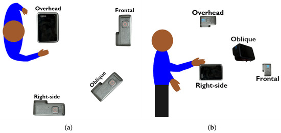
Figure 1.
(a) Overhead view of experimental setup, including GoPro camera locations relative to the participant. (b) Right-side view of experimental setup, including GoPro camera locations relative to the participant.
Calibration trials for the GoPro camera system were recorded prior to all participant trials using a ChArUco board (OpenCV version 4.7, Palo Alto, CA, USA. https://opencv.org/, accessed on 6 February 2024) [37] with a 5 × 7 grid, 36 mm checkers, 28 mm markers, and a 7 × 7 ArUco dictionary. Another calibration trial was recorded prior to individual participant trials to ensure that the calibration had not changed. The 4 GoPro Hero 11 Black cameras (GoPro, San Mateo, CA, USA) simultaneously recorded for approximately 1 min while the ChArUco board was tilted in all directions of the defined recording volume such that multiple cameras were able to view the target at the same time. These calibration trials were used later to determine intrinsic, extrinsic, and distortion parameters for the cameras as described by [38]. These parameters were then used to calibrate the positions of the cameras relative to each other using iterative bundle adjustment as described by [24].
In parallel, a 13-camera (10 Bonita, 2 Vero, 1 Vue) VICON optical motion capture system recording at 120 fps was used to collect ground truth wrist kinematic data. The VUE camera is capable of recording RGB video simultaneously with the remaining 12 (Bonita and Vero) infrared cameras. An Arduino Uno circuit placed in the field of view (FOV) of the GoPro cameras and the VUE camera was used to flash 3 different colored LEDs in rapid succession when triggered by an external remote. These LED flashes were used as a visual trigger to synchronize the video footage between each GoPro and the VICON VUE camera at the beginning of each participant trial.
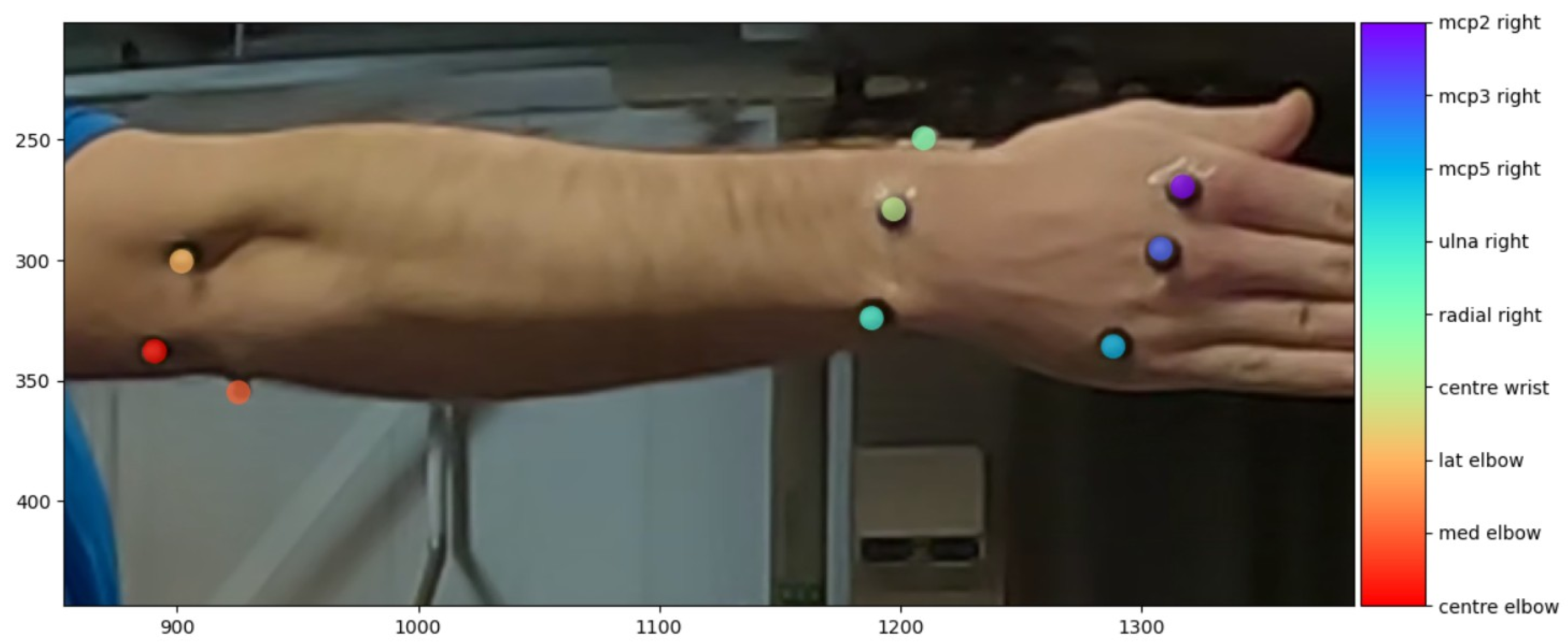
For each participant, nine 7.9 mm spherical retroreflective markers were placed on metacarpophalangeal joints (mcp) 2, 3, and 5; the radial and ulnar styloid processes; the midpoint between the radial and ulnar markers; the lateral and medial humeral epicondyles; and the center of the humeral epicondyle (Figure 2). The marker set was a modified version of the upper/lower arm segment defined for use in Visual3D [39] (Table 1). The joint coordinate system was defined according to the International Society for Biomechanics (ISB) guidelines [40] with a detailed definition as used by [41]. The center wrist marker was added to both the Visual3D markerset and referenced coordinate system to provide an additional point for tracking.

Figure 2.
Upper limb view of retroreflective marker placement as seen in DeepLabCut GUI for labeling images. See Table 2 for labeled marker descriptions.

Table 1.
DeepLabCut marker name and the relative anatomical landmark positions.
Participants were instructed to perform six trials, each including a series of range-of-motion (ROM) tasks (Table 2). To increase training data variability, 6 unique arm/wrist combinations were selected to encompass a larger area in each camera’s FOV. For each of the six trials, participants altered the arm position to one of six different positions relative to the torso and cameras. The order of presentation for each arm position was randomized between participants.
Table 2.
Arm position relative to the torso and wrist posture during the required range-of-motion tasks.
The six trials were designed to introduce positional variation within the capture volume, ensuring marker visibility across all camera views. Given that cameras were positioned in front of the participant and to the right side, participants performed trials while facing both the front camera and the right-side camera. This setup maximized the likelihood of capturing all markers accurately, as different arm positions relative to the torso and cameras compensated for potential occlusions. Furthermore, the selection of six trials was structured to balance data collection efficiency with the need for sufficient variation in movement planes. By maintaining this trial length, we ensured that adequate data were gathered for motion analysis within a reasonable time frame, minimizing participant fatigue.
2.2. Data Preprocessing
2.2.1. Video Editing
To synchronize data between the GoPro camera system and the optical motion capture system, the video data from both the GoPro and VICON systems were edited with Lossless Cut [42] to begin with the first frame following the LED illumination. Approximately 25 s of video content was used per trial after the video editing was complete.
2.2.2. VICON Data Processing
VICON data were processed and exported using Nexus 2.6 (Vicon Motion Systems Ltd., Oxford, UK). A custom Python 3.8 script analyzed the data and extracted wrist angles from marker locations. Euler angles were calculated with a ZYX rotation order where the Z axis defined FE and the X axis defined RUD [41,43]. These data were used as ground truth angular data.
2.2.3. K-Fold Cross Validation
A 4-fold cross-validation with different shuffles was implemented during the analysis pipeline. The data were split 4 different ways and each shuffle was independently used for the training and testing of the DLC model, Anipose, and wrist angle prediction methods. Each shuffle used the data from 12 of 16 subjects selected randomly without replacement as the training data, with the remaining 4 subjects being used as the testing dataset.
2.2.4. DeepLabCut Data Labeling and Model Training
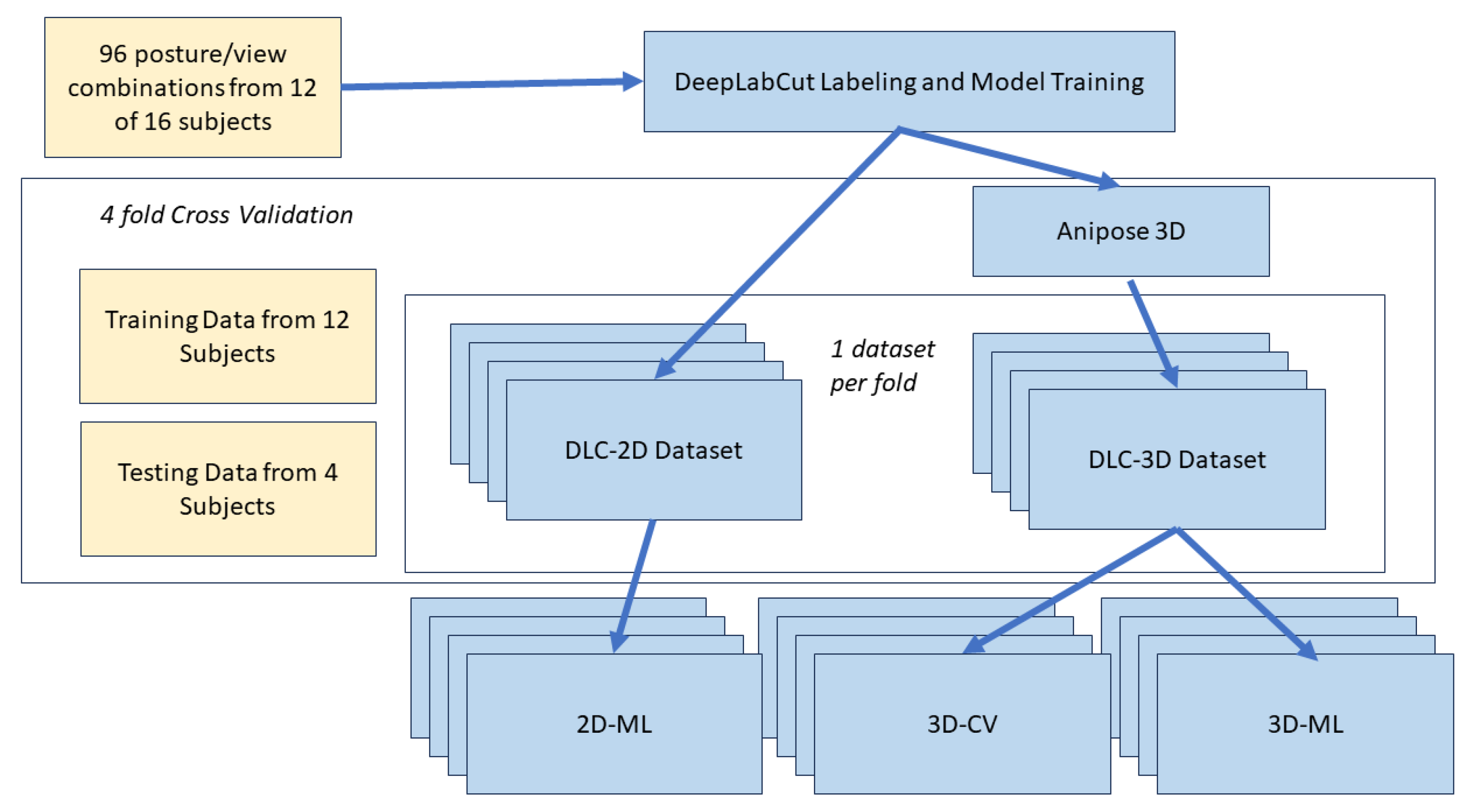
The process for DeepLabCut data labeling, model training, and 3D kinematic analysis is illustrated in Figure 3. Video data from 12 of the 16 subjects were used for DLC model training. Two trials from each of the 12 subjects were selected randomly from the 72 trials without replacement, resulting in 24 total trials used for labeling. As the 24 trials were recorded from 4 different camera angles, there were a total of 96 unique view/posture combinations used for labeling.
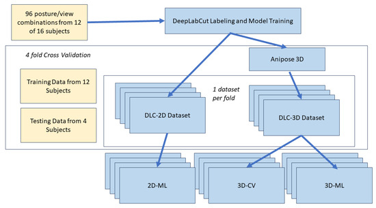
Figure 3.
Architecture for DeepLabCut data labeling, model training, and 3D kinematic analysis.
A k-means clustering function from DLC was used to extract 20 frames from each of the 96 labeling videos resulting in 480 frames per camera field of view for a total of 1920 labeled frames. The k-means clustering function downsamples each video, treats each frame as a vector, and clusters them together based on appearance [44]. Labeling manually identified the reflective marker associated with each anatomical landmark (Table 1) from an image using the DLC GUI (Figure 2). Labeling was performed by a single researcher. The labeled frames were then used to train a DLC model using a resnet-152 neural network for 250,000 iterations with the learning loss plateauing at 0.0013 error.
2.2.5. Anipose 3D Data Labeling and 3D Dataset
Anipose makes use of an iterative bundle adjustment to calibrate the parameters and relative locations of multiple cameras by analyzing the ChArUco board calibration trials [24]. The calibrate function in Anipose was applied to determine the parameters of each camera resulting in a reprojection error of 0.32 pixels, which is well below the 1 pixel threshold required to yield quality results [24]. For the triangulation and 3D filtering of data, optimization was enabled with spatiotemporal regularization using the parameters as defined in the Anipose tutorial [24,45]. The triangulate function was then used to combine and apply 3D filters to the 4 camera views into a single 3D time-series output for each marker location for each trial. These functions were used after the 2D videos were analyzed to create a 3D marker set. The result was a dataset containing the XYZ coordinates of each landmark location for every video frame. This dataset comprises the output of the multi-camera system and the open-source CV software (DLC3D). The VICON-generated angles were then appended to the DLC3D file to complete the dataset.
2.3. Wrist Angle Prediction with a Multi-Camera System and Open-Source Software (3DCV)
This method for wrist angle prediction used the DLC3D dataset with the addition of machine learning to determine if prediction accuracy could be improved over the DLC/Anipose approach outlined in Section 2.2.5. The XYZ marker locations established by DLC were used as the model features(attributes), and the FE and RUD angles were used for the model labels. The DLC3D dataset was divided into 4 shuffles that randomly selected 12 participants for training and 4 participants for testing without replacement. The 12-participant training set was then divided into an 80%/20% training/validation split for model training. The XYZ marker locations were used as the model features/attributes, and the FE and RUD angles were used for the model labels.
We used a number of ML algorithms able to accommodate varying and increasing levels of complexity, including linear, quadratic, and cubic regressions, as well as XGBRegressor, ridge regression with radial basis function kernel approximation, Support Vector Regressor (SVR), and deep neural networks. The performance of each algorithm was optimized through hyperparameter tuning using a GridSearchCV approach to search automatically through the hyperparameters listed in a parameter grid. An Adam optimizer [46], Relu activation function, and mean absolute error loss function provided the best results for all networks.
After the model was trained for each set of hyperparameters, the related training, validation, and testing error were recorded to determine the best model for this problem. Angles generated by these angle prediction models were compared to the angles generated from the OMC system during ROM trials. Training and validation mean absolute error (MAE) values were determined from the training dataset containing data from 12 of the participants. Testing MAE values were determined from the testing dataset containing data from the remaining 4 participants. MAE values were generated for each of the 4 shuffles.
A global feature importance metric was calculated for the highest performing model. Global feature importance is used to measure the importance of a feature for the entire model rather than a local importance which measures the contribution to a specific observation [47]. SHapley Additive exPlanation (SHAP) values were selected because they are a commonly used explainability technique for tabular datasets [48]. To assess which body marker locations had the greatest influence on the outcome, the top features of importance were calculated for FE and RUD separately. This was determined by taking the average positional value of the 10 top features of importance, across the 4 shuffles.
2.4. Wrist Angle Prediction Using Machine Learning and a Single Camera (2DML)
The DeepLabCut output from each camera position generated a dataset containing the XY coordinates of each anatomical landmark for every video frame. The VICON-derived joint angles were then appended to this dataset, forming the complete DLC2D dataset. This method for wrist angle prediction used the DLC2D dataset to assess the utility of a single camera with the addition of machine learning. To obtain accurate 2D joint angles, it is required that the camera be aligned with the movement plane [31]. The oblique camera was chosen as the most optimal oriented camera for this particular method. This ensured that the results were not biased toward any of the 4 different ROM tasks as the plane would not be aligned with any of the movements. Thus, the oblique camera data from the DLC2D dataset was used for training and testing. We used the same ML algorithms and performance optimization as described in Section 2.3. Similarly, the model training, fine-tuning, evaluation techniques, shuffling, and feature importance calculation from the 3DML method were used to evaluate the 2DML method.
2.5. Statistical Analysis
Repeated measures analyses of variance (RM-ANOVAs) were performed on the MAE data generated from the testing dataset, with the independent variable of model type. This analysis was performed separately for the FE and RUD data and for the single- and multi-camera systems to determine the best-performing model(s). Significance was set at p < 0.05. When appropriate, Bonferroni post-hoc analyses were performed.
3. Results
3.1. Wrist Angle Prediction Using a Multi-Camera System and Open-Source Software (3DCV)
The DLC/Anipose combination did not prove to be accurate in predicting wrist angles. Across four shuffles, the MAE was 99.1° for the FE and 25.3° for the RUD angles.
3.2. Wrist Angle Prediction Using Machine Learning and a Multi-Camera System (3DML)
When comparing the results of the different machine learning algorithms, reasonable accuracy was achieved using several machine learning algorithms (Table 3). The performance of the five-layer neural network achieved the lowest MAE for both FE (5.9°) and RUD (5.2°), which occurred from shuffle 1. The MAE values in Table 3 for FE and RUD represent the most accurate individual model results. Statistical analysis showed that cubic regression is a poor choice, while all other models examined exhibited similar performance. The best numbers are associated with both the neural network and support vector machine models for the multi-camera system.
Table 3.
Mean absolute error (MAE) plus/minus standard deviation (SD) results from testing data of predicted flexion/extension (FE) and radial/ulnar deviation (RUD) angle using a multi-camera system across four shuffles. Mean MAE values that do not share a letter are significantly different from one another.
The global feature importance analysis demonstrated that for both FE and RUD, the coordinates related to mcp2 were the most important, followed by the wrist coordinates, and the elbow coordinates were the least important. The top five features that affect FE angle prediction included the coordinates of the mcp2, the center of the wrist, and the ulna. The top five features that affect RUD angle prediction included the coordinates of mcp2, mcp3, the center of the wrist, and the ulna (Table 4). In general, the elbow markers were less important compared to the mcp and wrist markers.
Table 4.
Top 5 features of importance for flexion/extension (FE) and radial/ulnar deviation (RUD) as determined from a multi-camera system (3DML) and single-camera system (2DML).
3.3. Wrist Angle Prediction Using Machine Learning and a Single-Camera System (2DML)
When analyzing the results obtained from the single oblique camera for FE, several models (XGB regressor, RBF sampler and ridge regression, and the neural network) perform reasonably well (Table 5). The performance of the neural network achieved the lowest MAE for both flexion/extension and radial ulnar deviation angles. The overall best model with the lowest combined MAE resulted in flexion/extension MAE of 10.9° and a radial/ulnar MAE of 7.5° in shuffle 1. The MAE values in Table 5 for FE and RUD represent the most accurate individual model results. Again, the cubic regression model performed worse than the other models in all cases. Considering the other models for FE analysis, three models (XGB regressor, RBF sampler and ridge regression, and the deep neural network) have similar performance and are preferred to the other models. Turning to the RUD results, both the cubic and XGB regressor demonstrate poor results. The others show superior performance; however, the neural network noticeably has the lowest MAE.
Table 5.
Mean absolute error (MAE) plus/minus standard deviation (SD) from testing dataset of predicted flexion/extension (FE) and radial/ulnar deviation (RUD) angles using a single-camera system across four shuffles. Mean MAE values that do not share a letter are significantly different from one another.
The global feature importance analysis demonstrated that for both FE and RUD, coordinates relating to mcp were the most important in both FE and RUD, followed by wrist coordinates, with elbow coordinates the least important. The top five features affecting FE included coordinates from the mcp2, mcp3, center of wrist, and ulna. The top five features affecting RUD included coordinates from mcp2, mcp3, mcp5, and the radius (Table 4). Overall, the elbow markers were of the least importance when compared to the mcp and wrist markers.
4. Discussion
When using the low-cost four camera system with only open-source CV algorithms (Objective 1), large errors occurred when the markers were outside the field of view of the camera, distorted, or blurred within the camera view, resulting in inaccurate marker tracking. If the 3D marker location was inaccurate, the coordinate system vectors and resulting angles generated would also be inaccurate. The DLC/Anipose combination resulted in high errors (99° FE; 25° RUD) probably because the rotation matrices depended on accurate marker locations; if the joint center established via the two different methods is different, then large offsets and distortions can occur [18]. In conclusion, the CV methods investigated in this study as part of the first objective generated poor wrist angle predictions.
Machine learning (3DML) offered substantial improvement for wrist angle predictions compared to the computer vision method (3DCV). As displayed in Table 3, several models show promise at learning the inaccuracies and complex patterns associated with wrist movements. As noted in the results, the MAE of the 3DML method was as low as 5.9° for FE and 5.2° for RUD. In addition, the standard deviation across shuffles for the MAE was between 0.2 and 1.6° for all models except the worst-performing model, the cubic regression. This small standard deviation demonstrates how well the model can generalize to accurately predict wrist angle across a variety of subjects and arm orientations. The statistical analyses demonstrated that the worst prediction performance is associated with the cubic regression model. The accuracy of these models may be further improved with increased training data, and the methods described herein may provide the scaffolding for further development in the field of markerless motion capture.
As expected, the 2D single-camera method (2DML) (Table 5) was not as accurate when compared to the 3D multi-camera method (3DML) (Table 3). Similar to the case of the multiple camera, cubic regression performed the worst. The observed drop in accuracy compared to the 3DML method is probably because the 3D dataset provides marker depth to the system, which is important for predicting angles in multiple planes. As well, the z coordinate marker information provides an additional feature per landmark which may allow the model to learn additional patterns. As the system we used was comprised of four cameras, the inaccuracies of the DLC model were reduced as the marker location was triangulated between cameras. The 2D system is unable to use this method of triangulation to calculate the average marker center because the center of the marker gets expressed relative to the viewing angle in a 2D plane. For the 3D system, the added spatial data contained within the extra features resulted in improved accuracy.
Lahkar et al. determined an error of 14–20° for FE and 9.1–11° for RUD depending on arm orientation [18]. When comparing Lahkar’s result to ours, the current study demonstrated similar accuracy (12.2°) for FE and an improved accuracy for RUD (6.7°). Furthermore, the accuracy of 3DML improved FE error to 7.2° and RUD error to 5.5°.
Compared to a study that measured gait kinematics using the commercially available Theia MMC system, we observed similar results. In this instance, the foot was selected for comparison because it most closely replicates the ROM of a wrist. Kanko et al. found an ankle plantar flexion/dorsiflexion RMSE of 6.7° and an abduction/adduction RMSE of 11.6° [16]. Our measures compare favorably, with MAEs of 7.2 ± 0.9° for FE and 5.5° for RUD.
The elbow markers displayed low feature importance in both the 2DML and 3DML methods, indicating that there is a possibility the models could achieve similar results without the elbow features. This is a key piece of information for the deployment of this method as fewer markers would move this closer to being a truly markerless system. Additionally, removing the elbow markers would allow for different camera positioning that can focus on only the wrist and hand markers and potentially achieve higher accuracy in tracking those markers.
By using a grid search for multiple types of regression algorithms, we were able to determine which model provided the highest accuracy for the two individual ROMs, as well as the overall best algorithm. The support vector regressor showed promise as an accurate model, slightly outperforming the neural network for FE and RUD accuracy in shuffle 3 of 3DML and RUD accuracy in shuffle 4 of 3DML. However, the neural network provided better results across the individual shuffles for the lowest mean MAE in FE and RUD accuracy, except for shuffle 3 in 3DML. Though not statistically better, the neural network outperformed all models in every shuffle of 2DML for both FE and RUD.
It is evident from both Table 3 and Table 5 that the RUD angles were predicted with higher accuracy compared to the FE angles. The FE angle was consistently less accurate in both 2D and 3D applications, regardless of the model. As the FE ROM was larger than the RUD ROM, errors that occurred in the extreme values may have been larger for FE compared to RUD predictions. The higher error in FE predictions aligns with the trends commonly seen in the studies [18,41,49,50] which show that FE quantification poses a greater challenge.
A multi-camera system and a single-camera system for CV-generated data were both assessed for FE and RUD angle prediction. While the 2DML model was less accurate, it does pave the way for more analyses on how to use a single-camera for 3D wrist motion prediction. Two-dimensional systems have been shown to be an effective way to analyze an angle as long as the plane of movement is parallel to the FOV [14,31,51]. The camera used for the 2DML analysis was placed in an oblique position between the frontal and right-side cameras. This demonstrates that there is a possibility of achieving accurate angles in multiple planes even when the plane of movement is not parallel to the FOV. With this knowledge, it may be possible to develop a system that can predict wrist kinematics using a single-camera setup. Given that the model can predict angles when motion is not planar, the requirement for specific camera placement is eliminated. Requiring only a single camera ensures easier deployment outside of laboratory settings, making this an ideal candidate for workplace assessments. In addition, these results can help to push the field of markerless motion capture forward and increase the potential applications of using open-source methods.
The methods described in this paper have limitations. While the ultimate goal is to achieve a fully markerless system that requires a single camera, the limitation of using markers was necessary for validation against a gold-standard motion capture system. Comparison against an OMC has been seen in previous work as an effective way to assess the accuracy of an MMC while the participants still have markers present [16]. One of the main goals of this research is to provide a foundation for future research in the development of markerless motion capture systems to monitor wrist kinematics. As the feature importance value of the elbow markers is low across all models, it appears the elbow marker is less important than markers on the wrist and hand. There is a possibility that similar results could be achieved if the elbow markers were removed or not included. This would push the methodology closer towards the end goal of MMC for wrist kinematics. Future work could involve further validation of methods applied in this paper by virtually removing the markers through the application of advanced image editing techniques.
Another limitation is that subjects had a very clear and simplistic set of FE and RUD movements to complete. This was required to provide a clear idea of how well the methodology worked across subjects. If an alternative task was used that allowed subjects to move their upper limbs in a non-structured manner, it would be difficult to discern if inaccuracies in the model were subject-specific, task-specific, or if there was an overall inaccuracy. Future work could evaluate the accuracy of the various methods outlined in this paper while subjects complete simulated workplace tasks. Due to the nature of the experiment, the ability to generalize may be limited to the laboratory, as performance in settings outside of these confines may be inadequate. Additionally, as the population was selected based on convenience, there may be a limitation on how well the model may perform on a more diverse set of participants.
Overall, we have shown the ability to predict wrist angles with input from off-the-shelf, reasonably inexpensive cameras coupled with open-source algorithms confirms the potential to make MMC more accessible and available.
Author Contributions
Conceptualization, J.C., M.L.O. and K.D.G.; methodology, J.C.; software, J.C.; validation, J.C.; formal analysis, J.C.; investigation, J.C.; resources, M.L.O. and K.D.G.; data curation, J.C.; writing—original draft preparation, J.C.; writing—review and editing, M.L.O., K.D.G. and A.H.-W.; visualization, J.C.; supervision, M.L.O., A.H.-W., C.Y. and K.D.G.; project administration, J.C. All authors have read and agreed to the published version of the manuscript.
Funding
This research was funded by the Natural Sciences and Engineering Research Council of Canada, grant numbers RGPIN-2019-05240 and RGPIN-2019-05009.
Institutional Review Board Statement
This study was conducted in accordance with the Declaration of Helsinki and approved by the University of Guelph Research Ethics Board (REB #22-05-004).
Informed Consent Statement
Informed consent was obtained from all subjects involved in the study.
Data Availability Statement
The authors do not have permission to share data.
Conflicts of Interest
The authors declare no conflicts of interest.
References
- Blatter, B.M.; Bongers, P.M. Work Related Neck and Upper Limb Symptoms (RSI): High Risk Occupations and Risk Factors in the Dutch Working Population; Technical report; Netherlands Organization for Applied Scientific Research: Hague, The Netherlands, 1999; Available online: https://publications.tno.nl/publication/34613606/62U9cq/blatter-1999-workrelated.pdf (accessed on 17 December 2023).
- Palmer, K.T. Pain in the forearm, wrist and hand. Best Pract. Res. Clin. Rheumatol. 2003, 17, 113–135. [Google Scholar] [CrossRef]
- You, D.; Smith, A.H.; Rempel, D. Meta-Analysis: Association Between Wrist Posture and Carpal Tunnel Syndrome Among Workers. Saf. Health Work 2014, 5, 27–31. [Google Scholar] [CrossRef] [PubMed]
- Institute of Musculoskeletal Health and Arthritis. Strategic Plan 2014–2018, 2014. ISBN 978-1-100-25019-9. Available online: https://publications.gc.ca/site/eng/472758/publication.html (accessed on 1 November 2023).
- Tjepkema, M. Repetitive strain injury. Health Rep. 2003, 14, 11–30. [Google Scholar] [PubMed]
- Marín, J.; Marín, J.J. Forces: A Motion Capture-Based Ergonomic Method for the Today’s World. Sensors 2021, 21, 5139. [Google Scholar] [CrossRef]
- Caimmi, M.; Carda, S.; Giovanzana, C.; Maini, E.S.; Sabatini, A.M.; Smania, N.; Molteni, F. Using Kinematic Analysis to Evaluate Constraint-Induced Movement Therapy in Chronic Stroke Patients. Neurorehabilit. Neural Repair 2008, 22, 31–39. [Google Scholar] [CrossRef]
- Engdahl, S.M.; Gates, D.H. Reliability of upper limb and trunk joint angles in healthy adults during activities of daily living. Gait Posture 2018, 60, 41–47. [Google Scholar] [CrossRef]
- Henmi, S.; Yonenobu, K.; Masatomi, T.; Oda, K. A biomechanical study of activities of daily living using neck and upper limbs with an optical three-dimensional motion analysis system. Mod. Rheumatol. 2006, 16, 289–293. [Google Scholar] [CrossRef] [PubMed]
- Kontson, K.L.; Wang, S.; Barovsky, S.; Bloomer, C.; Wozniczka, L.; Civillico, E.F. Assessing kinematic variability during performance of Jebsen-Taylor Hand Function Test. J. Hand Ther. 2020, 33, 34–44. [Google Scholar] [CrossRef]
- Mackey, A.H.; Walt, S.E.; Lobb, G.A.; Stott, N.S. Reliability of upper and lower limb three-dimensional kinematics in children with hemiplegia. Gait Posture 2005, 22, 1–9. [Google Scholar] [CrossRef]
- Colyer, S.L.; Evans, M.; Cosker, D.P.; Salo, A.I.T. A Review of the Evolution of Vision-Based Motion Analysis and the Integration of Advanced Computer Vision Methods Towards Developing a Markerless System. Sport. Med.-Open 2018, 4, 24. [Google Scholar] [CrossRef]
- Harsted, S.; Holsgaard-Larsen, A.; Hestbæk, L.; Boyle, E.; Lauridsen, H.H. Concurrent validity of lower extremity kinematics and jump characteristics captured in pre-school children by a markerless 3D motion capture system. Chiropr. Man. Ther. 2019, 27, 39. [Google Scholar] [CrossRef]
- Schurr, S.A.; Marshall, A.N.; Resch, J.E.; Saliba, S.A. Two-dimensional video analysis is comparable to 3D motion capture in lower extremity movement assessment. Int. J. Sport. Phys. Ther. 2017, 12, 163–172. [Google Scholar] [PubMed] [PubMed Central]
- Simon, S.R. Quantification of human motion: Gait analysis—Benefits and limitations to its application to clinical problems. J. Biomech. 2004, 37, 1869–1880. [Google Scholar] [CrossRef] [PubMed]
- Kanko, R.M.; Laende, E.K.; Davis, E.M.; Selbie, W.S.; Deluzio, K.J. Concurrent assessment of gait kinematics using marker-based and markerless motion capture. J. Biomech. 2021, 127, 110665. [Google Scholar] [CrossRef]
- Riazati, S.; McGuirk, T.E.; Perry, E.S.; Sihanath, W.B.; Patten, C. Absolute Reliability of Gait Parameters Acquired With Markerless Motion Capture in Living Domains. Front. Hum. Neurosci. 2022, 16, 867474. [Google Scholar] [CrossRef]
- Lahkar, B.K.; Muller, A.; Dumas, R.; Reveret, L.; Robert, T. Accuracy of a markerless motion capture system in estimating upper extremity kinematics during boxing. Front. Sport. Act. Living 2022, 4, 939980. [Google Scholar] [CrossRef]
- Wade, L.; Needham, L.; McGuigan, P.; Bilzon, J. Applications and limitations of current markerless motion capture methods for clinical gait biomechanics. PeerJ 2022, 10, e12995. [Google Scholar] [CrossRef]
- Fang, H.S.; Li, J.; Tang, H.; Xu, C.; Zhu, H.; Xiu, Y.; Li, Y.L.; Lu, C. AlphaPose: Whole-Body Regional Multi-Person Pose Estimation and Tracking in Real-Time. IEEE Trans. Pattern Anal. Mach. Intell. 2023, 45, 7157–7173. [Google Scholar] [CrossRef]
- Cao, Z.; Hidalgo, G.; Simon, T.; Wei, S.E.; Sheikh, Y. OpenPose: Realtime Multi-Person 2D Pose Estimation Using Part Affinity Fields. IEEE Trans. Pattern Anal. Mach. Intell. 2021, 43, 172–186. [Google Scholar] [CrossRef]
- Jeong, S.o.; Kook, J. CREBAS: Computer-Based REBA Evaluation System for Wood Manufacturers Using MediaPipe. Appl. Sci. 2023, 13, 938. [Google Scholar] [CrossRef]
- Mathis, A.; Mamidanna, P.; Cury, K.M.; Abe, T.; Murthy, V.N.; Mathis, M.W.; Bethge, M. DeepLabCut: Markerless pose estimation of user-defined body parts with deep learning. Nat. Neurosci. 2018, 21, 1281–1289. [Google Scholar] [CrossRef] [PubMed]
- Karashchuk, P.; Rupp, K.L.; Dickinson, E.S.; Walling-Bell, S.; Sanders, E.; Azim, E.; Brunton, B.W.; Tuthill, J.C. Anipose: A toolkit for robust markerless 3D pose estimation. Cell Rep. 2021, 36, 109730. [Google Scholar] [CrossRef] [PubMed]
- He, K.; Zhang, X.; Ren, S.; Sun, J. Deep Residual Learning for Image Recognition. In Proceedings of the 2016 IEEE Conference on Computer Vision and Pattern Recognition (CVPR), Las Vegas, NV, USA, 27–30 June 2016; pp. 770–778. [Google Scholar] [CrossRef]
- Lei, M.; Wang, Z.; Chen, F. Ballet Form Training Based on MediaPipe Body Posture Monitoring. J. Phys. Conf. Ser. 2023, 2637, 012019. [Google Scholar] [CrossRef]
- Insafutdinov, E.; Pishchulin, L.; Andres, B.; Andriluka, M.; Schiele, B. DeeperCut: A Deeper, Stronger, and Faster Multi-person Pose Estimation Model. In Computer Vision—ECCV 2016; Leibe, B., Matas, J., Sebe, N., Welling, M., Eds.; Springer International Publishing: Cham, Switzerland, 2016; Volume 9910, pp. 34–50. [Google Scholar] [CrossRef]
- Pishchulin, L.; Insafutdinov, E.; Tang, S.; Andres, B.; Andriluka, M.; Gehler, P.; Schiele, B. DeepCut: Joint Subset Partition and Labeling for Multi Person Pose Estimation. In Proceedings of the 2016 IEEE Conference on Computer Vision and Pattern Recognition (CVPR), Las Vegas, NV, USA, 27–30 June 2016; pp. 4929–4937. [Google Scholar] [CrossRef]
- Fiker, R.; Kim, L.H.; Molina, L.A.; Chomiak, T.; Whelan, P.J. Visual Gait Lab: A user-friendly approach to gait analysis. J. Neurosci. Methods 2020, 341, 108775. [Google Scholar] [CrossRef]
- Gupta, A.; Shrestha, P.L.; Thapa, B.; Silwal, R.; Shrestha, R. Knee Flexion/Extension Angle Measurement for Gait Analysis Using Machine Learning Solution “MediaPipe Pose” and Its Comparison with Kinovea. IOP Conf. Ser. Mater. Sci. Eng. 2023, 1279, 012004. [Google Scholar] [CrossRef]
- Stenum, J.; Rossi, C.; Roemmich, R.T. Two-dimensional video-based analysis of human gait using pose estimation. PLoS Comput. Biol. 2021, 17, e1008935. [Google Scholar] [CrossRef]
- Tang, Y.-m.; Wang, Y.-H.; Feng, X.-Y.; Zou, Q.-S.; Wang, Q.; Ding, J.; Shi, R.C.-J.; Wang, X. Diagnostic value of a vision-based intelligent gait analyzer in screening for gait abnormalities. Gait Posture 2022, 91, 205–211. [Google Scholar] [CrossRef]
- Fan, J.; Gu, F.; Lv, L.; Zhang, Z.; Zhu, C.; Qi, J.; Wang, H.; Liu, X.; Yang, J.; Zhu, Q. Reliability of a human pose tracking algorithm for measuring upper limb joints: Comparison with photography-based goniometry. BMC Musculoskelet. Disord. 2022, 23, 877. [Google Scholar] [CrossRef]
- Goulermas, J.Y.; Howard, D.; Nester, C.J.; Jones, R.K.; Ren, L. Regression Techniques for the Prediction of Lower Limb Kinematics. J. Biomech. Eng. 2005, 127, 1020–1024. [Google Scholar] [CrossRef]
- Ren, S.; Wang, W.; Hou, Z.G.; Chen, B.; Liang, X.; Wang, J.; Peng, L. Personalized gait trajectory generation based on anthropometric features using Random Forest. J. Ambient. Intell. Humaniz. Comput. 2019, 14, 15597–15608. [Google Scholar] [CrossRef]
- Sivakumar, S.; Gopalai, A.A.; Lim, K.H.; Gouwanda, D. Artificial neural network based ankle joint angle estimation using instrumented foot insoles. Biomed. Signal Process. Control 2019, 54, 101614. [Google Scholar] [CrossRef]
- Garrido-Jurado, S.; Muñoz Salinas, R.; Madrid-Cuevas, F.; Marín-Jiménez, M. Automatic generation and detection of highly reliable fiducial markers under occlusion. Pattern Recognit. 2014, 47, 2280–2292. [Google Scholar] [CrossRef]
- Zhang, Z. A flexible new technique for camera calibration. IEEE Trans. Pattern Anal. Mach. Intell. 2000, 22, 1330–1334. [Google Scholar] [CrossRef]
- HAS-Motion. Marker Set Guidelines—Visual3D Wiki Documentation. 2024. Available online: https://wiki.has-motion.com/index.php/Marker_Set_Guidelines#References (accessed on 17 December 2023).
- Wu, G.; Van Der Helm, F.C.; DirkJan Veeger, H.; Makhsous, M.; Van Roy, P.; Anglin, C.; Nagels, J.; Karduna, A.R.; McQuade, K.; Wang, X.; et al. ISB recommendation on definitions of joint coordinate systems of various joints for the reporting of human joint motion–Part II: Shoulder, elbow, wrist and hand. J. Biomech. 2005, 38, 981–992. [Google Scholar] [CrossRef]
- Young, C.; DeDecker, S.; Anderson, D.; Oliver, M.L.; Gordon, K.D. Accuracy of a Low-Cost 3D-Printed Wearable Goniometer for Measuring Wrist Motion. Sensors 2021, 21, 4799. [Google Scholar] [CrossRef] [PubMed]
- Finstad, M. Mifi/Lossless-Cut, Original-Date: 30 October 2016. 2023. Available online: https://github.com/mifi/lossless-cut (accessed on 17 December 2023).
- Hillstrom, H.J.; Garg, R.; Kraszewski, A.; Lenhoff, M.; Carter, T.; Backus, S.I.; Wolff, A.; Syrkin, G.; Cheng, R.; Wolfe, S.W. Development of an Anatomical Wrist Joint Coordinate System to Quantify Motion During Functional Tasks. J. Appl. Biomech. 2014, 30, 586–593. [Google Scholar] [CrossRef]
- DeepLabCut. DeepLabCut User Guide (for Single Animal Projects). 2023. Available online: https://deeplabcut.github.io/DeepLabCut/docs/standardDeepLabCut_UserGuide.html (accessed on 6 February 2024).
- Anipose. Anipose Tutorial—Anipose 0.8.1 Documentation. 2020. Available online: https://anipose.readthedocs.io/en/latest/tutorial.html (accessed on 17 December 2023).
- Kingma, D.P.; Ba, J. Adam: A Method for Stochastic Optimization. arXiv 2017, arXiv:1412.6980. [Google Scholar]
- Saarela, M.; Jauhiainen, S. Comparison of feature importance measures as explanations for classification models. SN Appl. Sci. 2021, 3, 272. [Google Scholar] [CrossRef]
- Munn, M.; Pitman, D. Explainable AI for Practitioners: Designing and Implementing Explainable ML Solutions; O’Reilly: Beijing, China; Sebastopol, CA, USA,, 2022. [Google Scholar]
- McHugh, B.P.; Morton, A.M.; Akhbari, B.; Molino, J.; Crisco, J.J. Accuracy of an electrogoniometer relative to optical motion tracking for quantifying wrist range of motion. J. Med. Eng. Technol. 2020, 44, 49–54. [Google Scholar] [CrossRef]
- McKinnon, C.D.; Ehmke, S.; Kociolek, A.M.; Callaghan, J.P.; Keir, P.J. Wrist Posture Estimation Differences and Reliability Between Video Analysis and Electrogoniometer Methods. Hum. Factors J. Hum. Factors Ergon. Soc. 2021, 63, 1284–1294. [Google Scholar] [CrossRef]
- Kidzínski, L.; Yang, B.; Hicks, J.L.; Rajagopal, A.; Delp, S.L.; Schwartz, M.H. Deep neural networks enable quantitative movement analysis using single-camera videos. Nat. Commun. 2020, 11, 4054. [Google Scholar] [CrossRef] [PubMed]

Disclaimer/Publisher’s Note: The statements, opinions and data contained in all publications are solely those of the individual author(s) and contributor(s) and not of MDPI and/or the editor(s). MDPI and/or the editor(s) disclaim responsibility for any injury to people or property resulting from any ideas, methods, instructions or products referred to in the content. |
© 2025 by the authors. Licensee MDPI, Basel, Switzerland. This article is an open access article distributed under the terms and conditions of the Creative Commons Attribution (CC BY) license (https://creativecommons.org/licenses/by/4.0/).