

Fracture Prediction in Weldox 700E Steel Subjected to High Velocity Impact Using LS-DYNA


Abstract
1. Introduction
2. Materials and Methods
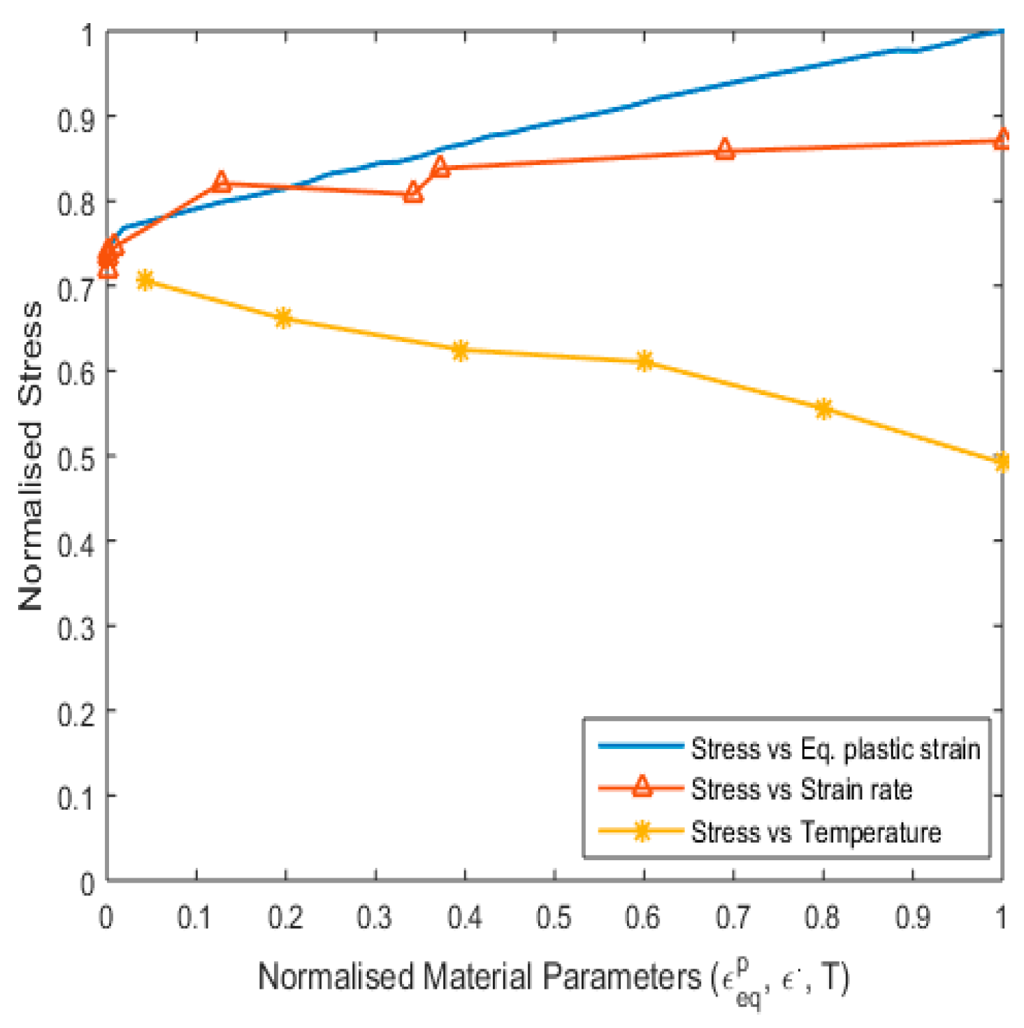
2.1. Material Model
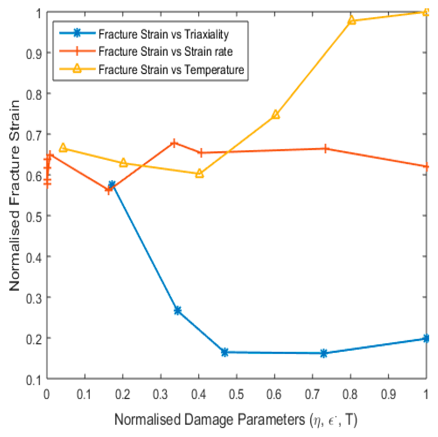
2.2. Fracture Model
2.3. Material and Fracture Model Constants
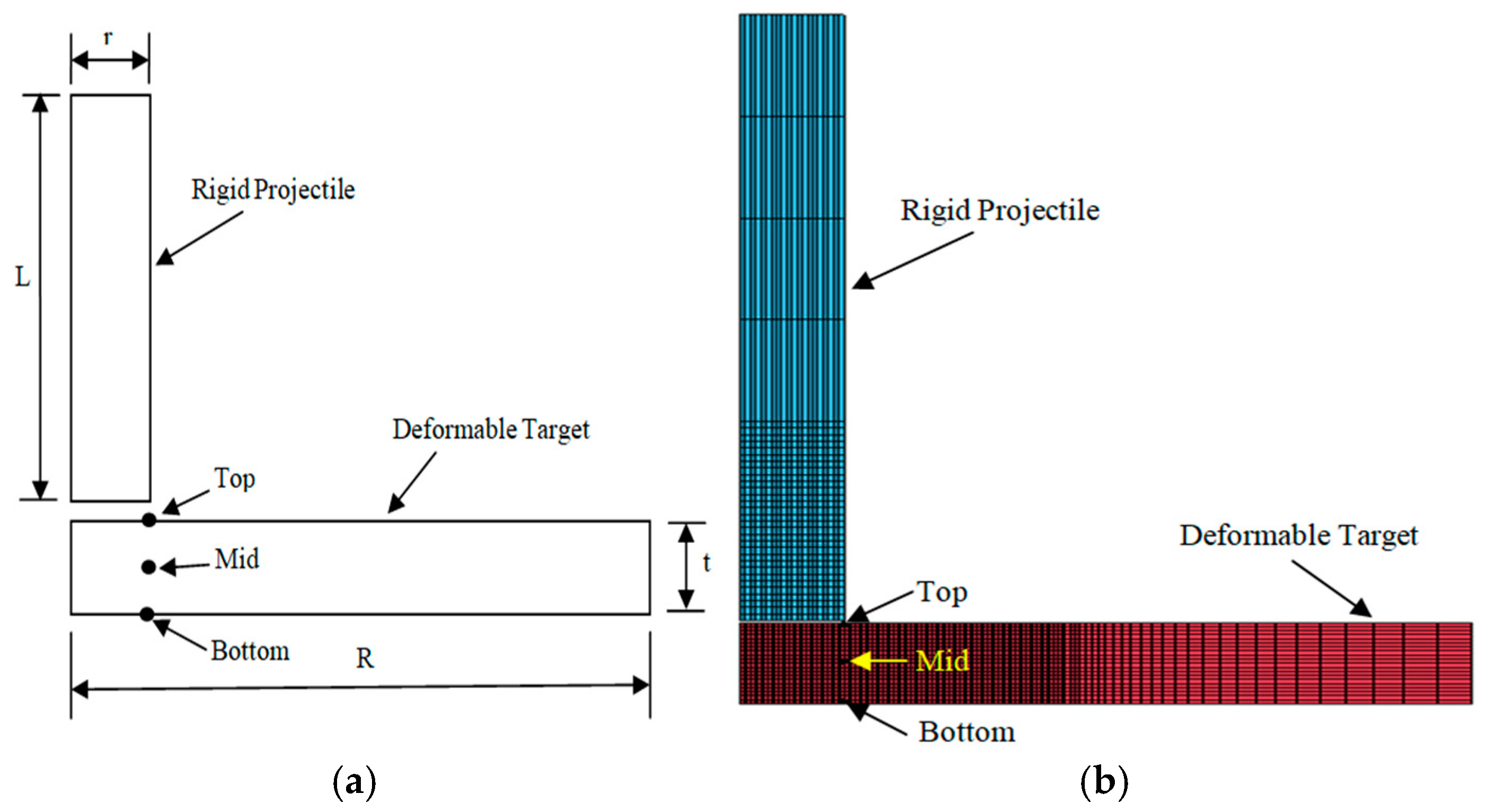
2.4. Model Description
3. Results and Discussion
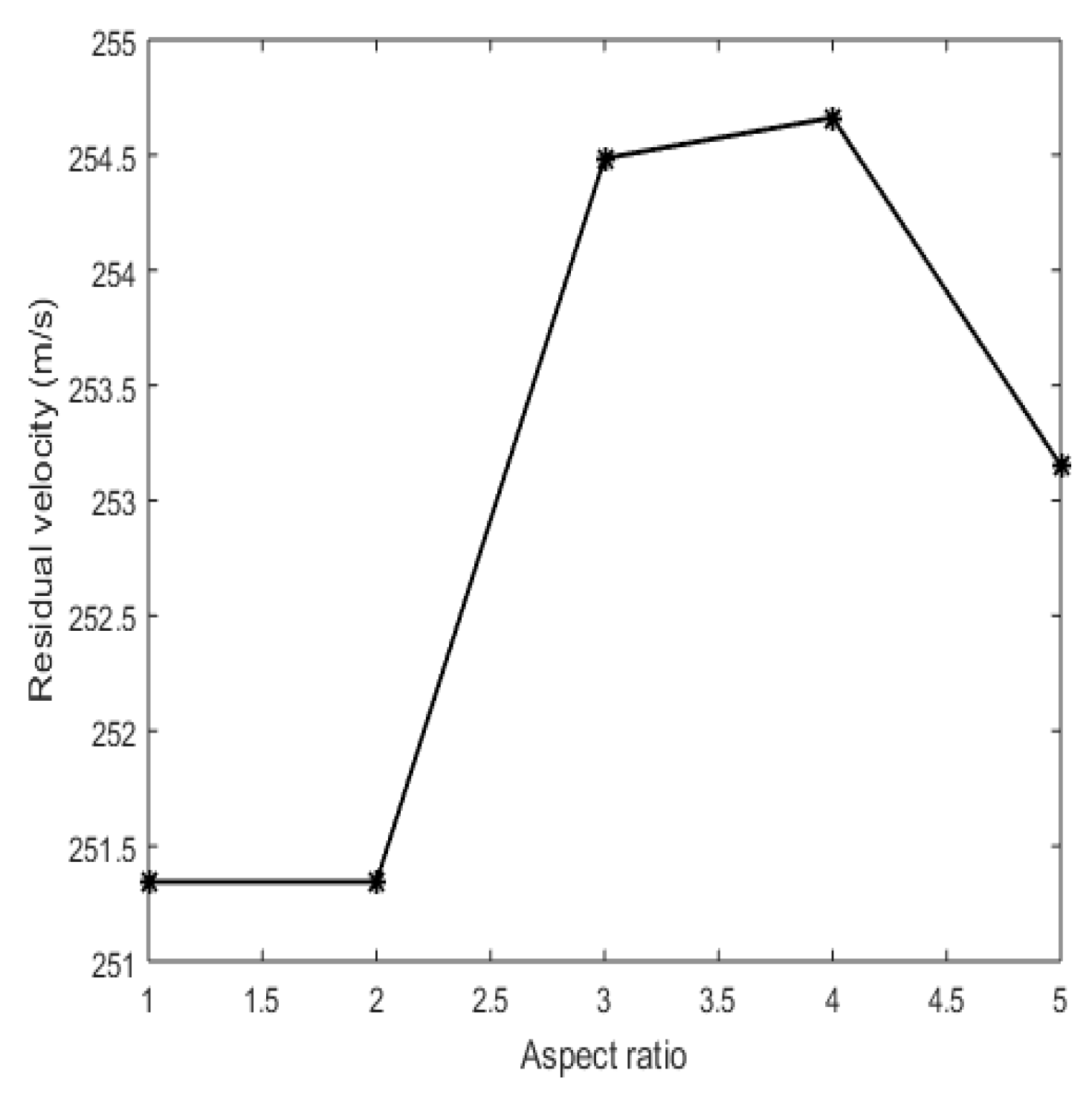
3.1. Mesh Convergence Study
3.2. Validation
3.2.1. Validation for Deformation with No Fracture in Taylor Rod
3.2.2. Validation for Deformation with Fracture in Target Plate
3.3. Investigation of Fracture Behaviour
3.3.1. Fracture Behaviour with Varying Critical Fracture Parameter (Dc)
- (a)
- Plug formation
- (b)
- Contour plots for von Mises stress
- (c)
- Effect on fracture parameters
3.3.2. Fracture Behaviour with Varying Fracture Strain Criteria
- (a)
- Plug formation
- (b)
- Effect on fracture parameters
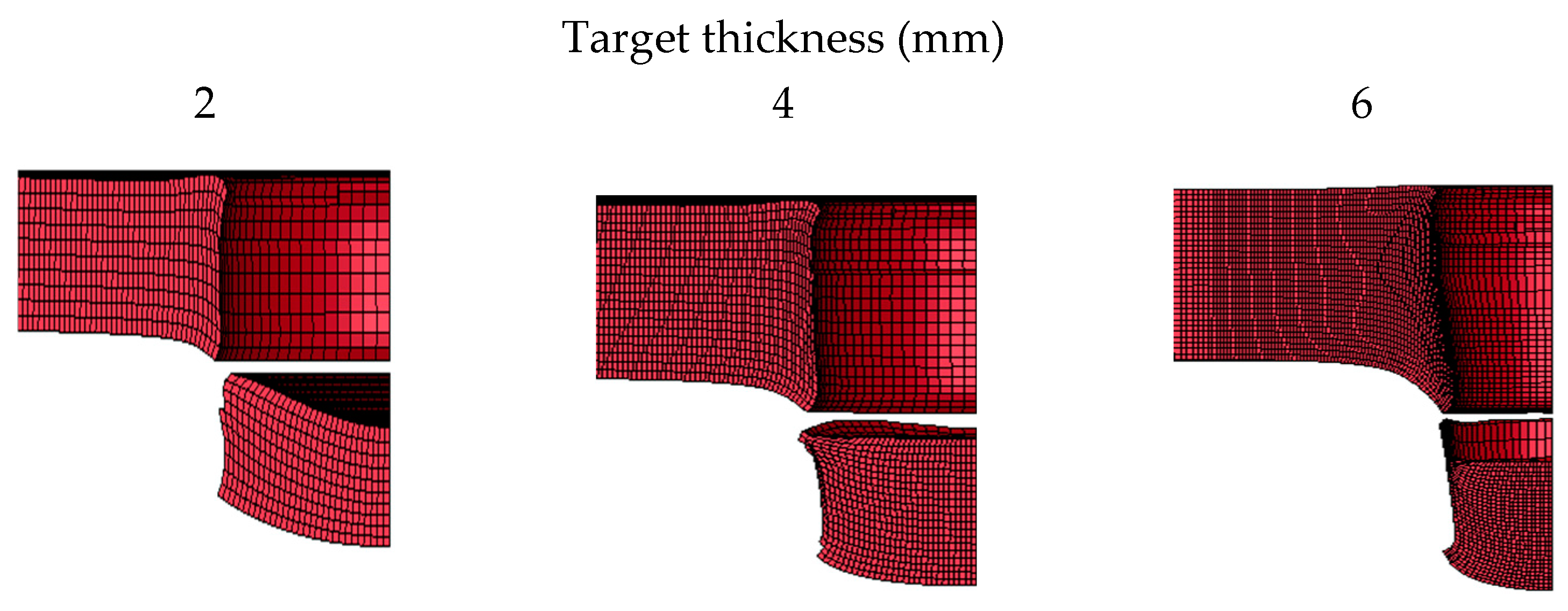
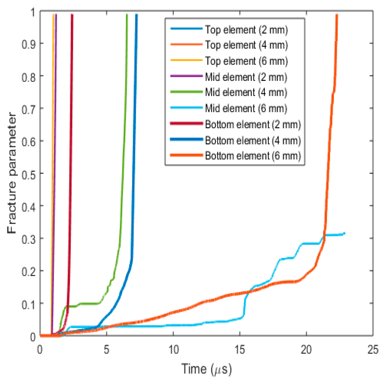
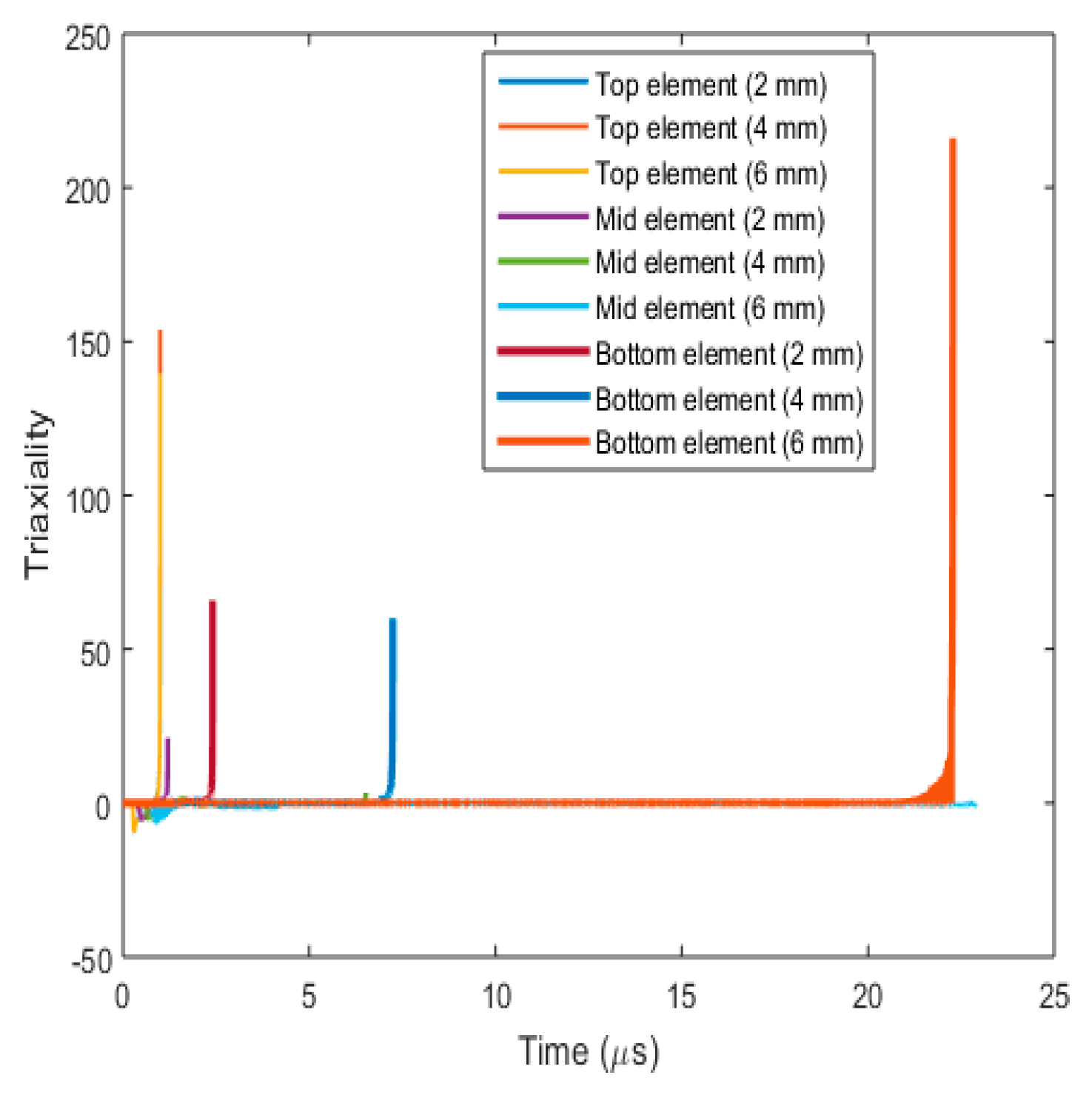
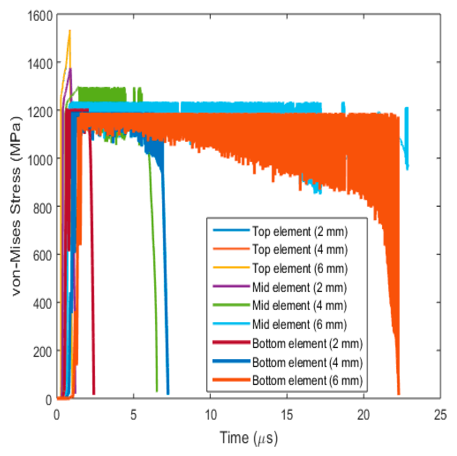
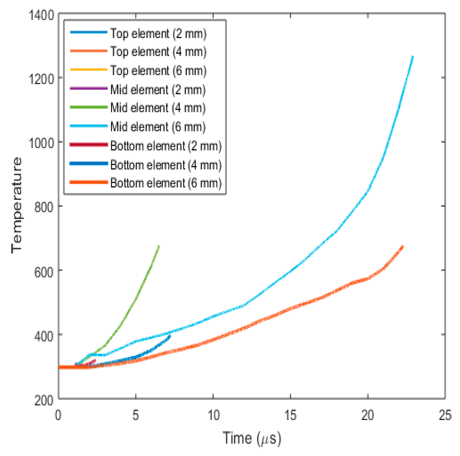
3.3.3. Fracture Behaviour with Varying Target Plate Thickness
- (a)
- Plug formation
- (b)
- Effect on fracture parameters
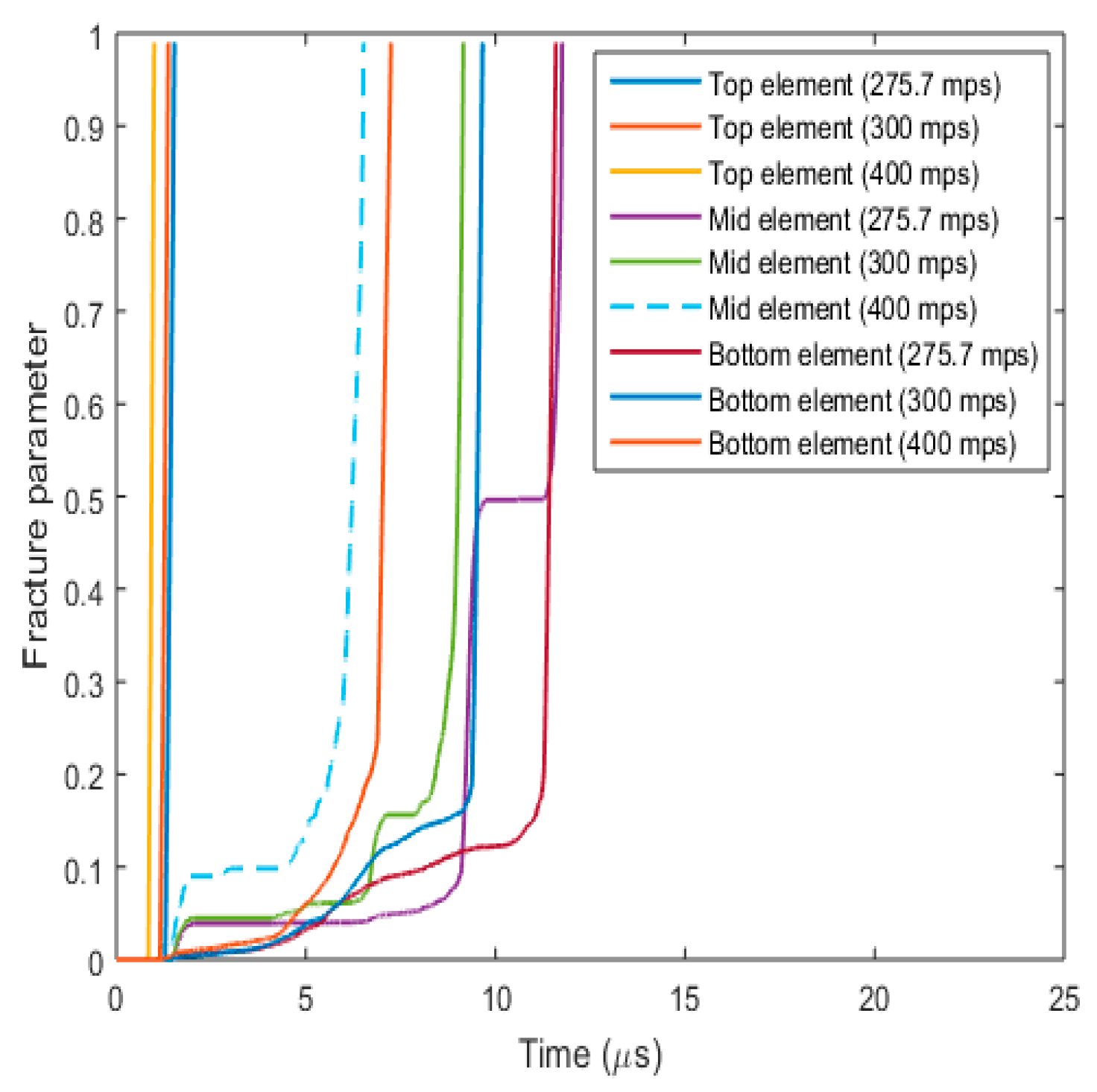
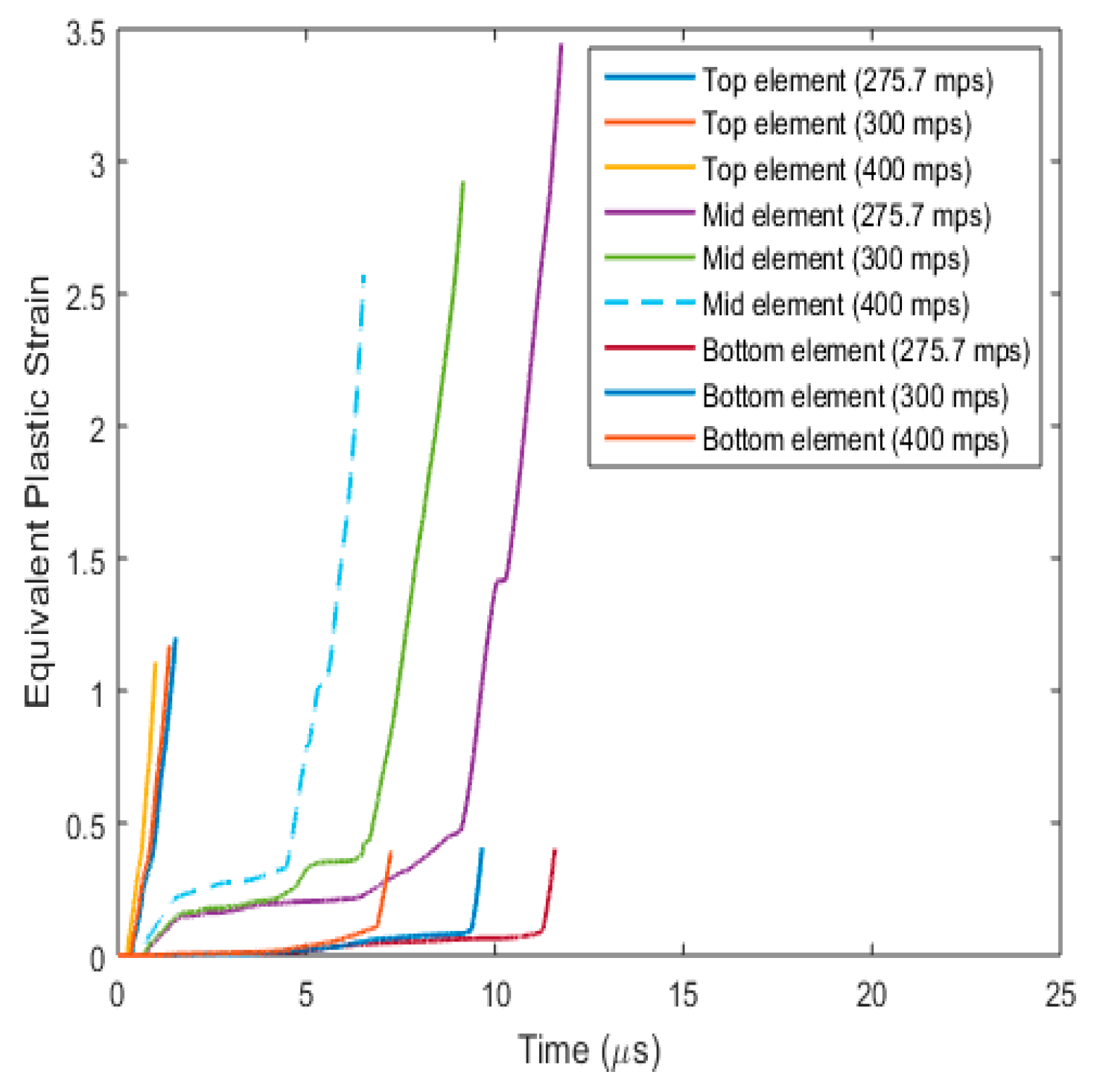
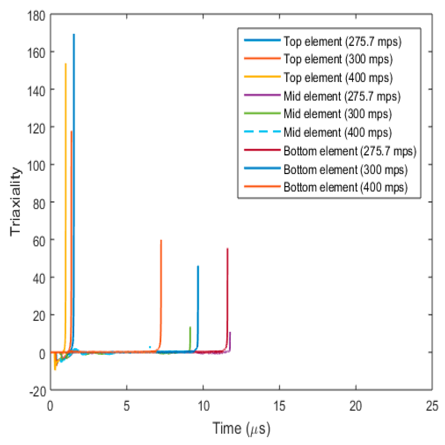
3.3.4. Fracture Behaviour with Varying Projectile Velocity
- (a)
- Plug formation
- (b)
- Effect on fracture parameters
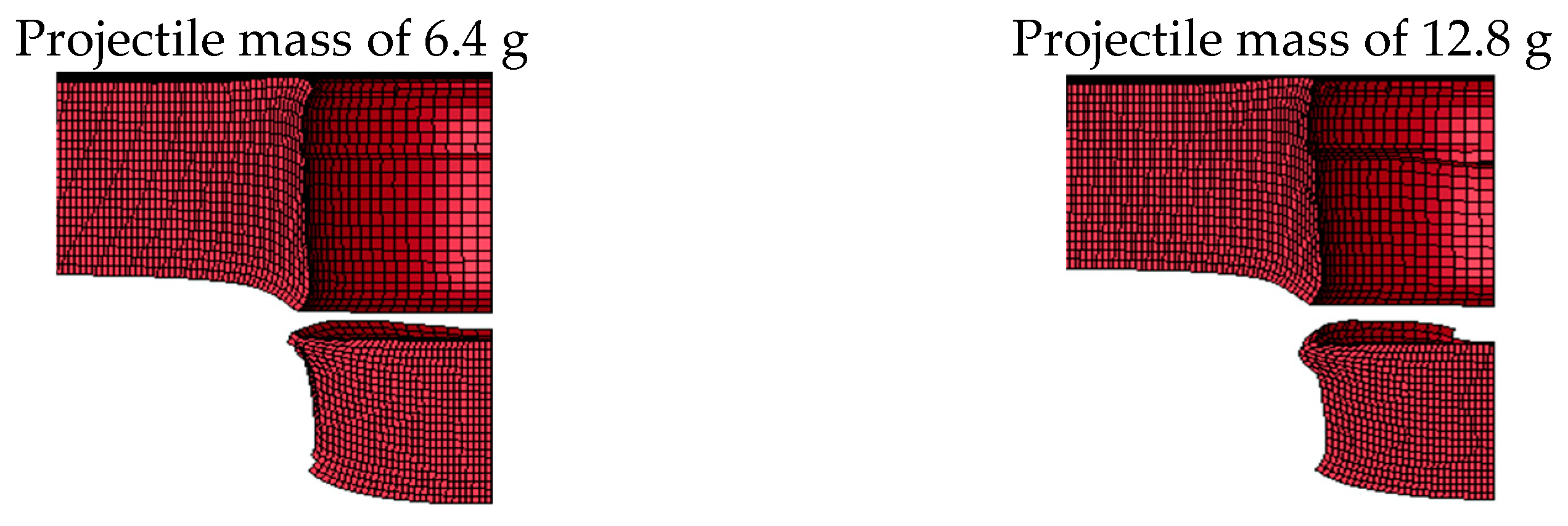
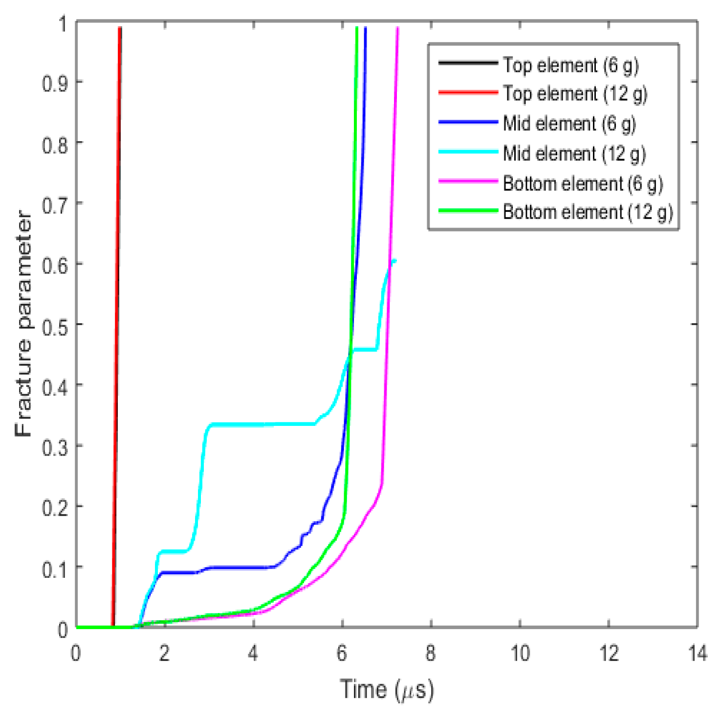
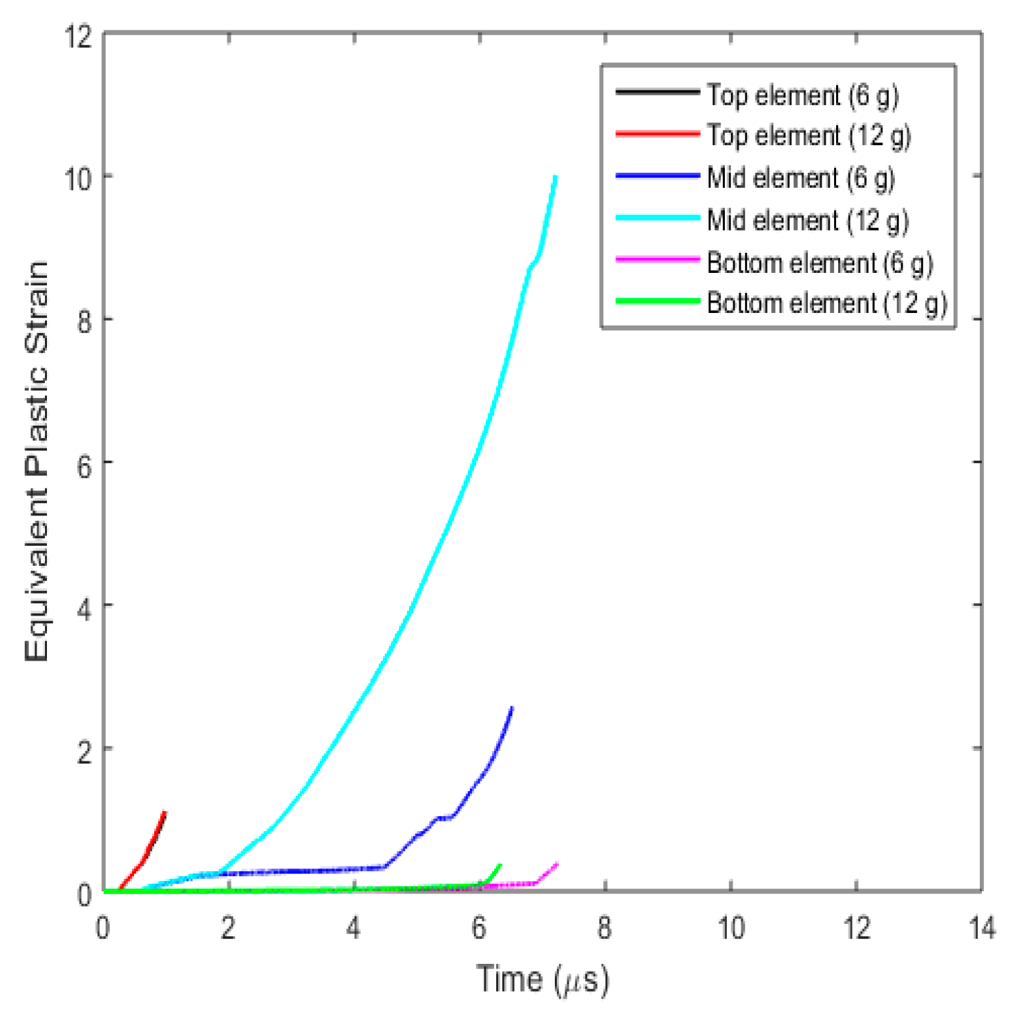
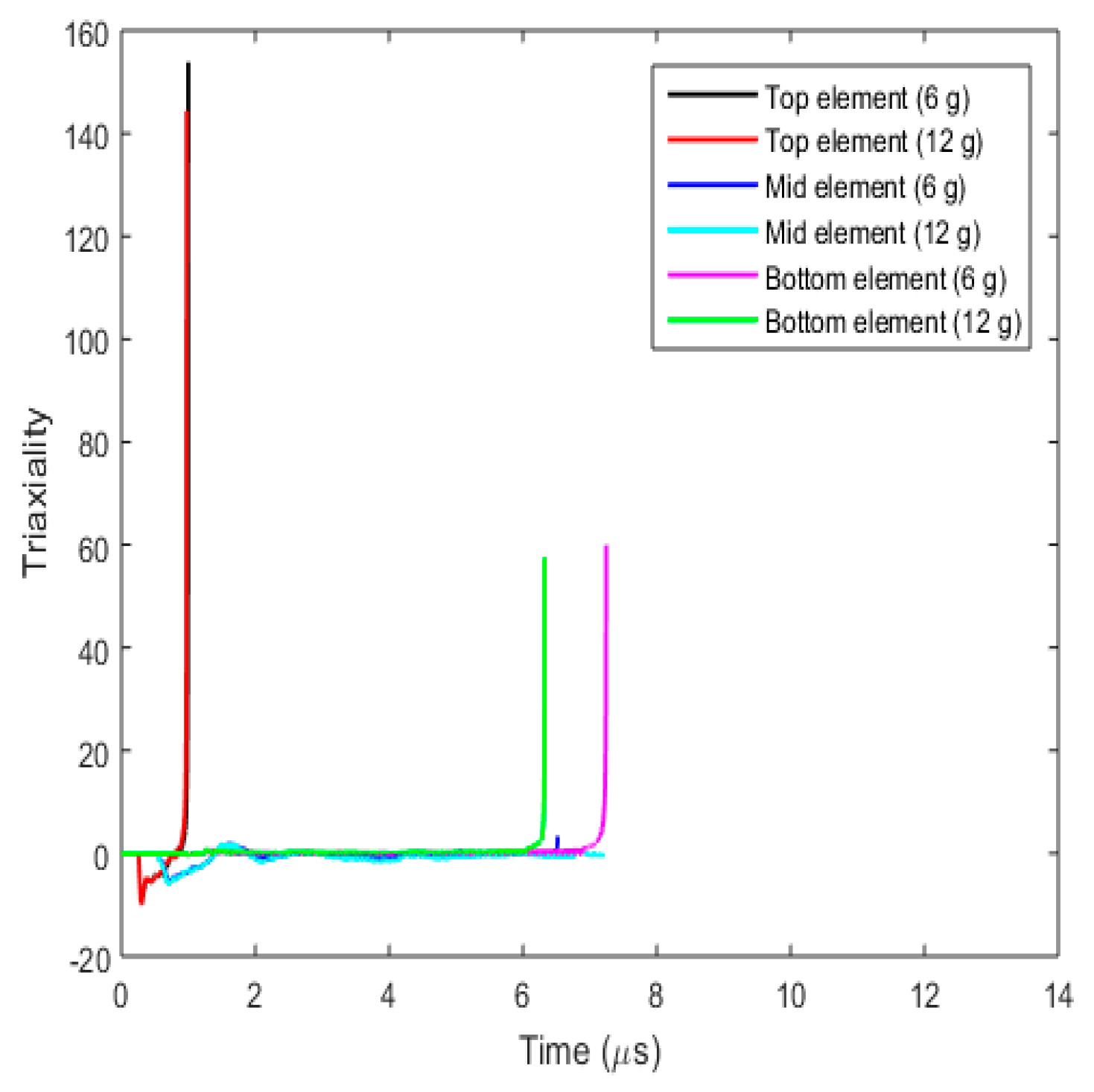
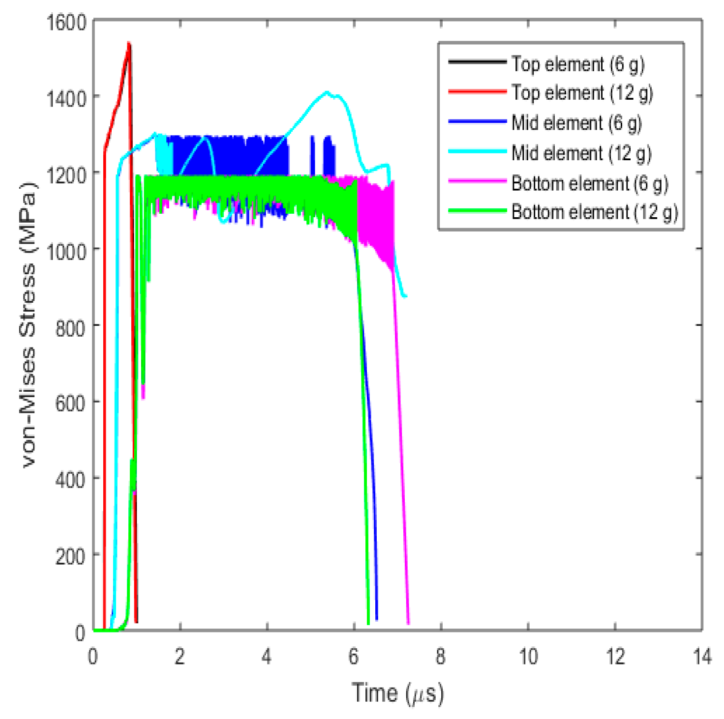
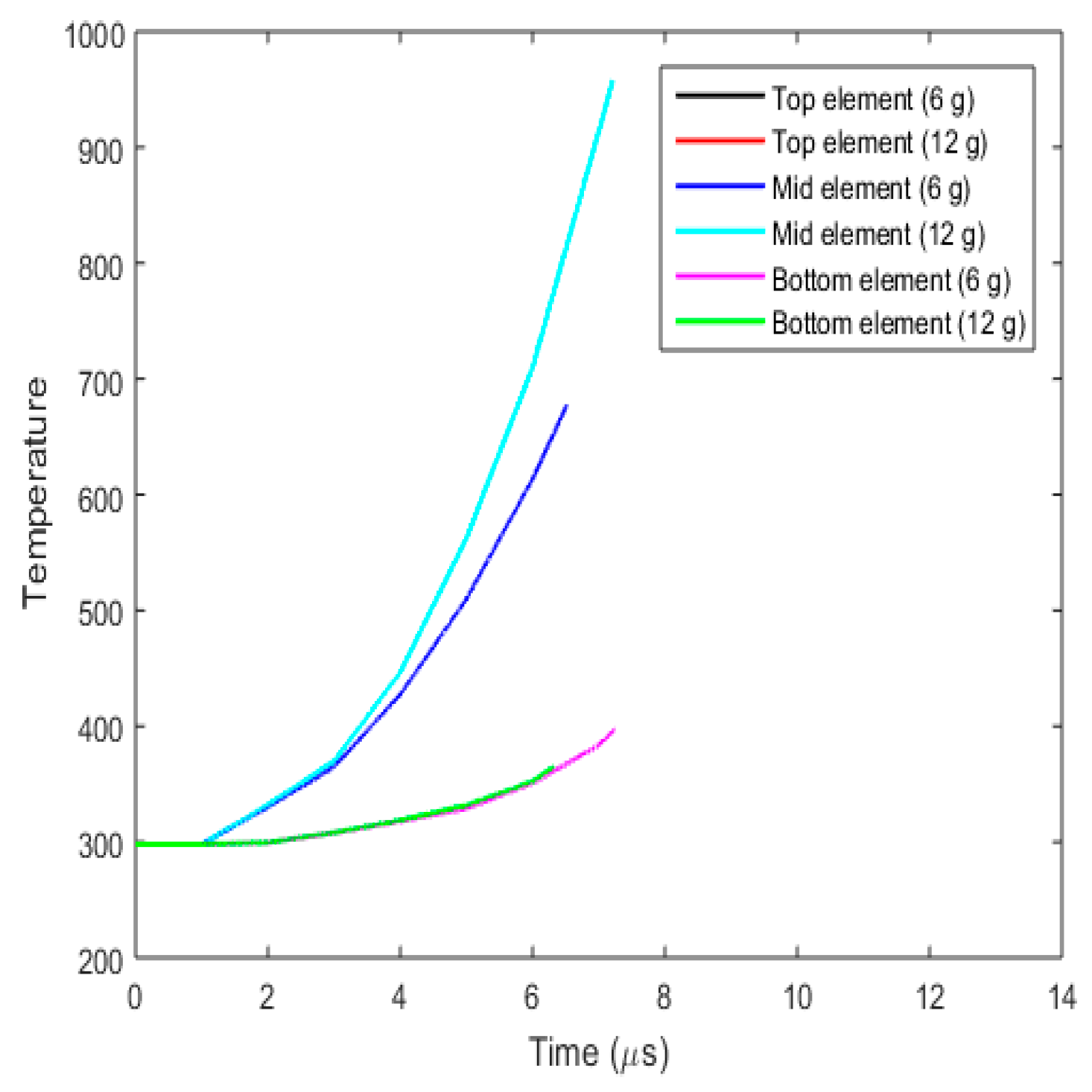
3.3.5. Fracture Behaviour with Varying Projectile Mass
- (a)
- Plug formation
- (b)
- Effect on fracture parameters
4. Conclusions
Author Contributions
Funding
Institutional Review Board Statement
Informed Consent Statement
Data Availability Statement
Acknowledgments
Conflicts of Interest
References
- Rao, C.L.; Narayanamurthy, V.; Simha, K. Applied Impact Mechanics; John Wiley & Sons: West Sussex, UK, 2016. [Google Scholar]
- Borvik, T.; Hopperstad, O.; Berstad, T.; Langseth, M. Numerical simulation of plugging failure in ballistic penetration. Int. J. Solids Struct. 2001, 38, 6241–6264. [Google Scholar]
- Borvik, T.; Langseth, M.; Hopperstad, O.; Malo, K. Perforation of 12 mm thick steel plates by 20 mm diameter projectiles with flat, hemispherical and conical noses: Part i: Experimental study. Int. J. Impact Eng. 2002, 27, 19–35. [Google Scholar]
- Borvik, T.; Hopperstad, O.S.; Langseth, M.; Malo, K.A. Effect of target thickness in blunt projectile penetration of weldox 460 e steel plates. Int. J. Impact Eng. 2003, 28, 413–464. [Google Scholar]
- Dey, S.; Borvik, T.; Hopperstad, O.; Leinum, J.; Langseth, M. The effect of target strength on the perforation of steel plates using three different projectile nose shapes. Int. J. Impact Eng. 2004, 30, 1005–1038. [Google Scholar]
- Dey, S.; Borvik, T.; Teng, X.; Wierzbicki, T.; Hopperstad, O. On the ballistic resistance of double-layered steel plates: An experimental and numerical investigation. Int. J. Solids Struct. 2007, 44, 6701–6723. [Google Scholar]
- Dey, S.; Borvik, T.; Hopperstad, O.; Langseth, M. On the influence of constitutive relation in projectile impact of steel plates. Int. J. Impact Eng. 2007, 34, 464–486. [Google Scholar]
- Borvik, T.; Dey, S.; Clausen, A. Perforation resistance of five different high strength steel plates subjected to small-arms projectiles. Int. J. Impact Eng. 2009, 36, 948–964. [Google Scholar]
- Iqbal, M.; Senthil, K.; Bhargava, P.; Gupta, N. The characterization and ballistic evaluation of mild steel. Int. J. Impact Eng. 2015, 78, 98–113. [Google Scholar]
- Gupta, N.K.; Iqbal, M.A.; Sekhon, G.S. Effect of projectile nose shape, impact velocity and target thickness on the deformation behaviour of layered plates. Int. J. Impact Eng. 2008, 35, 37–60. [Google Scholar]
- Costas, M.; Edwards-Mowforth, M.; Kristoffersen, M.; Teixeira-Dias, F.; Brøtan, V.; Paulsen, C.O.; Børvik, T. Ballistic impact resistance of additive manufactured high-strength maraging steel: An experimental study. Int. J. Prot. Struct. 2021, 12, 577–603. [Google Scholar]
- Lou, Y.; Huh, H. Prediction of ductile fracture for advanced high strength steel with a new criteria: Experiments and simulation. J. Mater. Process. Technol. 2013, 213, 1284–1302. [Google Scholar] [CrossRef]
- Xue, L.; Wierzbicki, T. Ductile fracture initiation and propagation modeling using fracture plasticity theory. Eng. Fract. Mech. 2008, 75, 3276–3293. [Google Scholar] [CrossRef]
- Wierzbicki, T.; Xue, L. On the Effect of the Third Invariant of the Stress Deviator on Ductile Fracture; Technical Report; Impact and Crashworthiness Laboratory: Cambridge, MA, USA, 2005; Volume 136. [Google Scholar]
- Wciślik, W.; Pała, R. Some microstructural aspects of ductile fracture of metals. Materials 2021, 14, 4321. [Google Scholar] [CrossRef]
- Baral, M.; Ripley, P.W.; Lou, Y.; Korkolis, Y.P. Anisotropic ductile fracture of a stainless steel under biaxial loading: Experiments and predictions. Int. J. Plast. 2024, 175, 103927. [Google Scholar]
- Liu, Y.; Ikeda, S.; Liu, Y.; Ge, H. Ductile Fracture Investigation of High-Strength Steel SM570 under Low Stress Triaxiality. Metals 2022, 12, 1394. [Google Scholar] [CrossRef]
- Ghosh, A.; Ghosh, M. Tensile and impact behaviour of thermo mechanically treated and micro-alloyed medium carbon steel bar. Constr. Build. Mater. 2018, 192, 657–670. [Google Scholar] [CrossRef]
- Mao, K.; Toussaint, G.; Komrakova, A.; Hogan, J.D. High-velocity impact failure modeling of Armox 500T steel: Model validation and application to structural design. Int. J. Impact Eng. 2024, 183, 104790. [Google Scholar]
- Baysal, A.; Turkmen, H.S.; Yayla, P. High-velocity impact behaviour of nonwoven mats and unidirectional prepreg hemp and flax fibers reinforced hybrid biocomposites. Polym. Compos. 2024, 45, 5399–5415. [Google Scholar]
- Stamoulis, K.; Georgantzinos, S.K.; Giannopoulos, G. Damage characteristics in laminated composite structures subjected to low-velocity impact. Int. J. Struct. Integr. 2020, 11, 670–685. [Google Scholar] [CrossRef]
- Ul Haq, A.; Narala, S.K.R. High-velocity impact performance of sandwich panels with additively manufactured hierarchical honeycomb cores: An experimental and numerical study. J. Sandw. Struct. Mater. 2024, 26, 524–544. [Google Scholar] [CrossRef]
- Rodríguez-María, J.; García-Castillo, S.K.; Iváñez, I.; Navarro, C. Experimental and analytical study of the behaviour of in-plane preloaded CFRP plates subjected to high-velocity impact. Mech. Adv. Mater. Struct. 2024, 31, 2509–2519. [Google Scholar]
- Gautam, S.S.; Babu, R.; Dixit, P.M. Ductile fracture simulation in the Taylor rod impact test using continuum fracture mechanics. Int. J. Fract. Mech. 2011, 20, 347–369. [Google Scholar]
- Indriyantho, B.R.; Zreid, I.; Fleischhauer, R.; Kaliske, M. Modelling of high velocity impact on concrete structures using a rate-dependent plastic-fracture micro plane approach at finite strains. Materials 2020, 13, 5165. [Google Scholar] [CrossRef]
- Xiao, X.; Wang, Y.; Vershinin, V.V.; Chen, L.; Lou, Y. Effect of lode angle in predicting the ballistic resistance of Weldox 700 e steel plates struck by blunt projectiles. Int. J. Impact Eng. 2019, 128, 46–71. [Google Scholar]
- Johnson, G.R.; Cook, W.H. Fracture characteristics of three metals subjected to various strains, strain rates, temperatures and pressures. Eng. Fract. Mech. 1985, 21, 31–48. [Google Scholar]
- K.U.S. Manual. Keyword User’s Manual, Volume II; LSTC. 2012. Available online: https://ftp.lstc.com/anonymous/outgoing/jday/manuals/LS-DYNA_manual_Vol_II_R6.1.0.pdf (accessed on 20 November 2024).
- Lemaitre, J.; Desmorat, R. Engineering Fracture Mechanics: Ductile, Creep, Fatigue and Brittle Failures; Springer: Berlin/Heidelberg, Germany, 2006. [Google Scholar]
- Teng, X.; Wierzbicki, T. Numerical study on crack propagation in high velocity perforation. Comput. Struct. 2005, 83, 989–1004. [Google Scholar]
- Timoshenko, S.; Woinowsky-Krieger, S. Theory of Plates and Shells, 2nd ed.; McGraw- Hill Book Company: New York, NY, USA, 1959. [Google Scholar]
- Jasra, Y.; Saxena, R.K. Fracture behaviour of prestressed ductile target subjected to high velocity impact-Numerical study. Appl. Comput. Mech. 2022, 16, 101–118. [Google Scholar]
- Bai, Y.L.; Dodd, B. Adiabatic Shear Localization: Occurrence, Theories, and Applications; Pergamon Press: Oxford, UK, 1992. [Google Scholar]
- Saxena, R.K.; Dixit, P.M. Numerical analysis of fracture for prediction of fracture initiation in deep drawing. Finite Elem. Anal. Des. 2011, 47, 1104–1117. [Google Scholar] [CrossRef]
- Celentano, D.J. Thermomechanical analysis of the Taylor impact test. J. Appl. Phys. 2002, 91, 3675–3686. [Google Scholar]


| Material Constants | Notation | Value |
|---|---|---|
| Young’s modulus (GPa) | E | 210 |
| Poisson’s ratio | ν | 0.33 |
| Density (kg/m3) | ρ | 7850 |
| Initial Yield Stress (MPa) | A | 913 |
| Hardening Coefficient (MPa) | B | 275 |
| Hardening exponent | r | 0.8215 |
| Strain rate hardening | N | 0.0161 |
| Thermal softening constant | q | 1.0875 |
| Reference strain rate (s−1) | Ɛ0 | 5 × 10⁻⁴ |
| Reference temperature (K) | T0 | 298 |
| Melting temperature (K) | Tm | 1800 |
| Specific heat (J/kg-K) | cp | 452 |
| Fracture strain | D1 | 0.365 |
| D2 | 4.5296 | |
| D3 | −5.0397 | |
| D4 | −0.0033 | |
| D5 | 1.3864 |
| Material Constants | Notation | Value |
|---|---|---|
| Young’s modulus (GPa) | E | 204 |
| Poisson’s ratio | ν | 0.33 |
| Density (kg/m3) | ρ | 7750 |
| Initial Yield Stress (MPa) | A | 1900 |
| Hardening Coefficient (MPa) | B | 15,000 |
| Aspect Ratio | No. of Elements | No. of Nodes |
|---|---|---|
| Aspect ratio 1 | 535,800 | 568,465 |
| Aspect ratio 2 | 267,900 | 291,165 |
| Aspect ratio 3 | 214,320 | 235,705 |
| Aspect ratio 4 | 133,950 | 152,515 |
| Aspect ratio 5 | 107,160 | 124,785 |
| Length Ratio | Radius Ratio | |
|---|---|---|
| Experimental | 0.66 | 2.220 |
| Present work | 0.65 | 2.219 |
| Fracture Strain Criterion | D1 | D2 | D3 | D4 | D5 | D6 |
|---|---|---|---|---|---|---|
| ef-JC | 0.365 | 4.5296 | −5.0397 | −0.0033 | 1.3864 | --- |
| ef-DJC | 0.365 | 4.5296 | −5.0397 | −0.0022 | 1.3864 | --- |
| ef-XJC | 0.365 | 4.5296 | −5.0397 | −0.0033 | 7.5177 | 2.1484 |
Disclaimer/Publisher’s Note: The statements, opinions and data contained in all publications are solely those of the individual author(s) and contributor(s) and not of MDPI and/or the editor(s). MDPI and/or the editor(s) disclaim responsibility for any injury to people or property resulting from any ideas, methods, instructions or products referred to in the content. |
© 2025 by the authors. Licensee MDPI, Basel, Switzerland. This article is an open access article distributed under the terms and conditions of the Creative Commons Attribution (CC BY) license (https://creativecommons.org/licenses/by/4.0/).
Share and Cite
Ojha, N.K.; Saxena, R.K.; Vashishtha, G.; Chauhan, S. Fracture Prediction in Weldox 700E Steel Subjected to High Velocity Impact Using LS-DYNA. Appl. Sci. 2025, 15, 3677. https://doi.org/10.3390/app15073677
Ojha NK, Saxena RK, Vashishtha G, Chauhan S. Fracture Prediction in Weldox 700E Steel Subjected to High Velocity Impact Using LS-DYNA. Applied Sciences. 2025; 15(7):3677. https://doi.org/10.3390/app15073677
Chicago/Turabian StyleOjha, Nikesh Kumar, Ravindra K. Saxena, Govind Vashishtha, and Sumika Chauhan. 2025. "Fracture Prediction in Weldox 700E Steel Subjected to High Velocity Impact Using LS-DYNA" Applied Sciences 15, no. 7: 3677. https://doi.org/10.3390/app15073677
APA StyleOjha, N. K., Saxena, R. K., Vashishtha, G., & Chauhan, S. (2025). Fracture Prediction in Weldox 700E Steel Subjected to High Velocity Impact Using LS-DYNA. Applied Sciences, 15(7), 3677. https://doi.org/10.3390/app15073677