Development of Parametric Prostheses for Different Levels of Human Hand Amputations Manufactured Through Additive Manufacturing

 ,
,
Abstract
:1. Introduction
2. Methodology
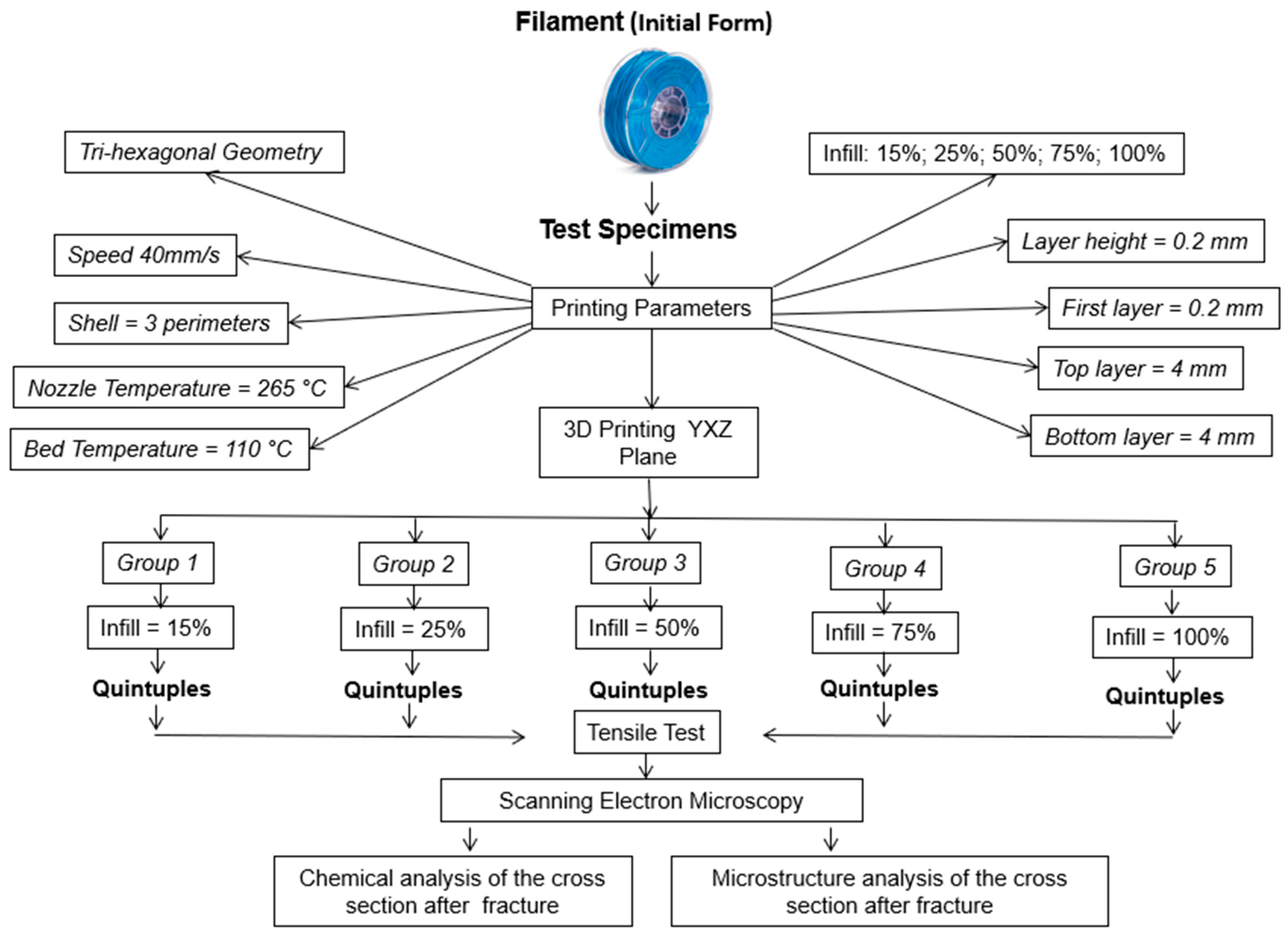
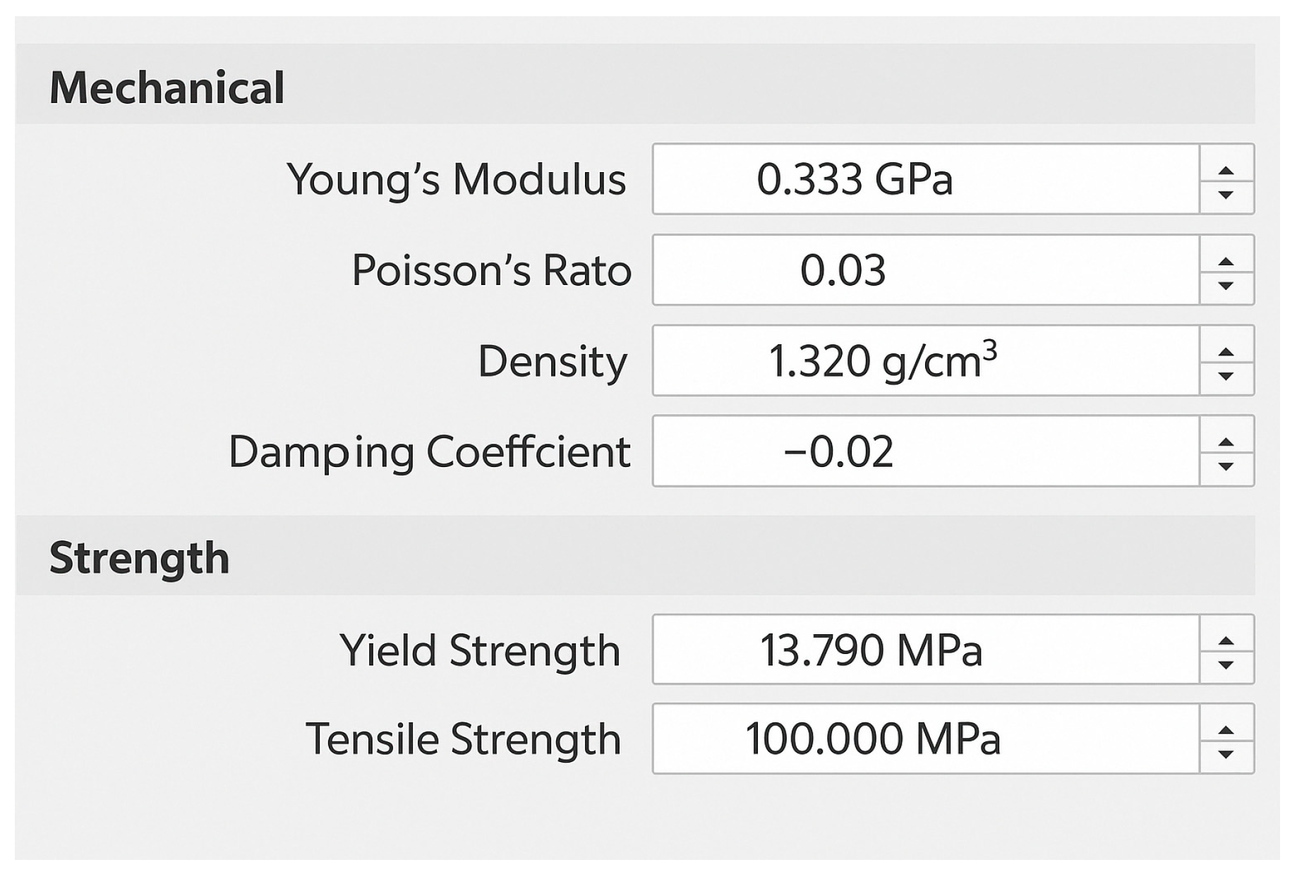
2.1. Material
2.2. Equipment
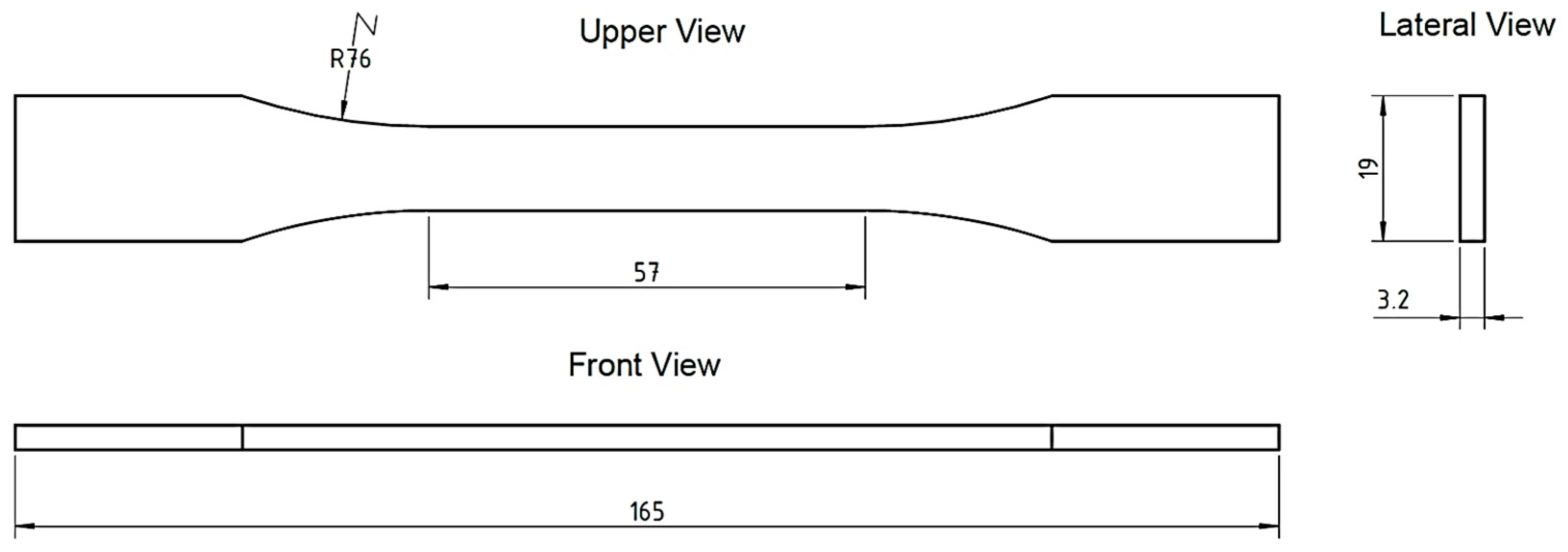
2.3. Normalization
2.4. Experimental Test
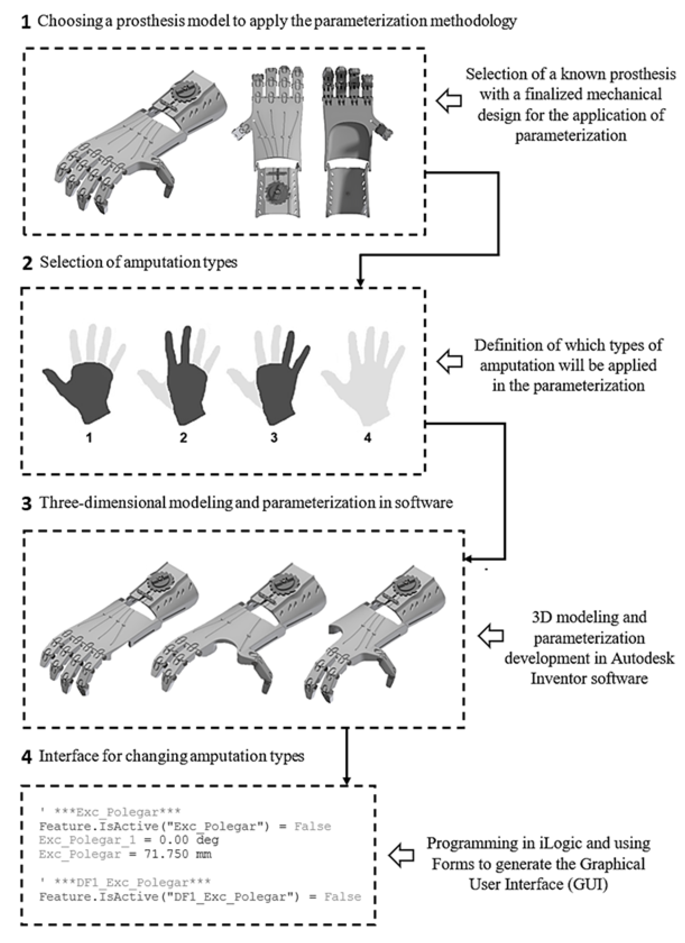
2.5. Development of the Hand Prosthesis Parameterization
2.6. Selection of the Prosthetic Device
2.7. Selection of Hand Amputation Types
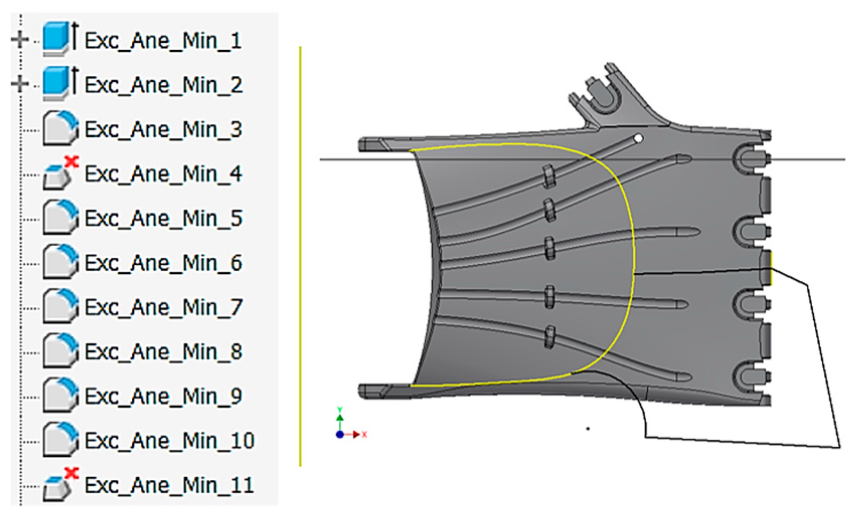
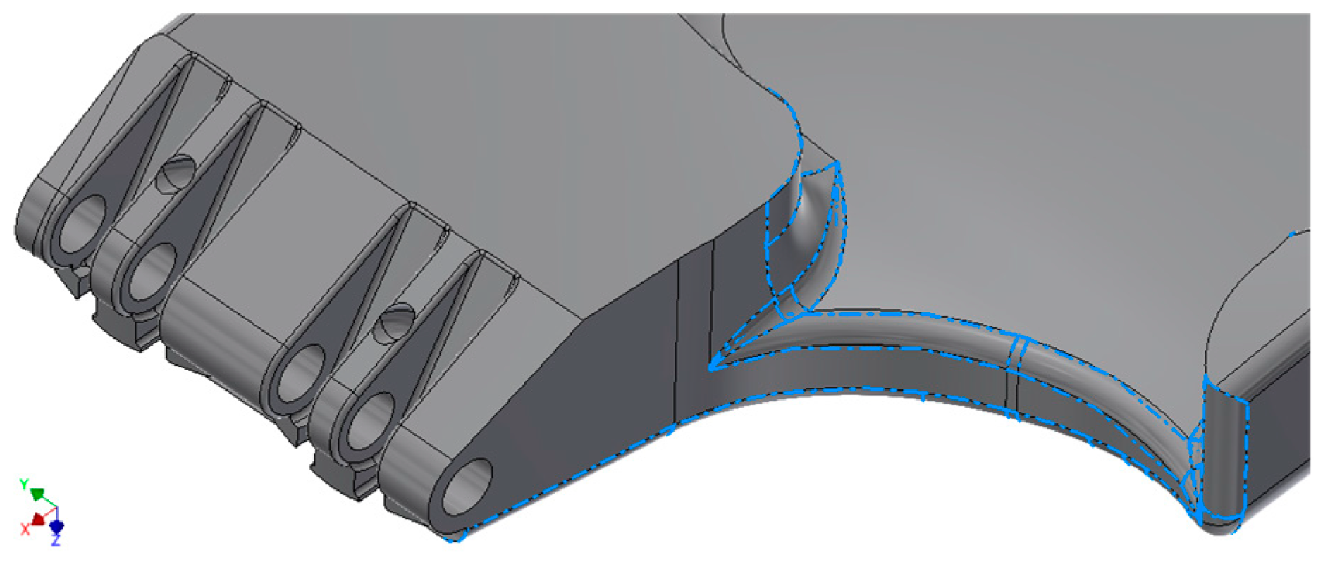
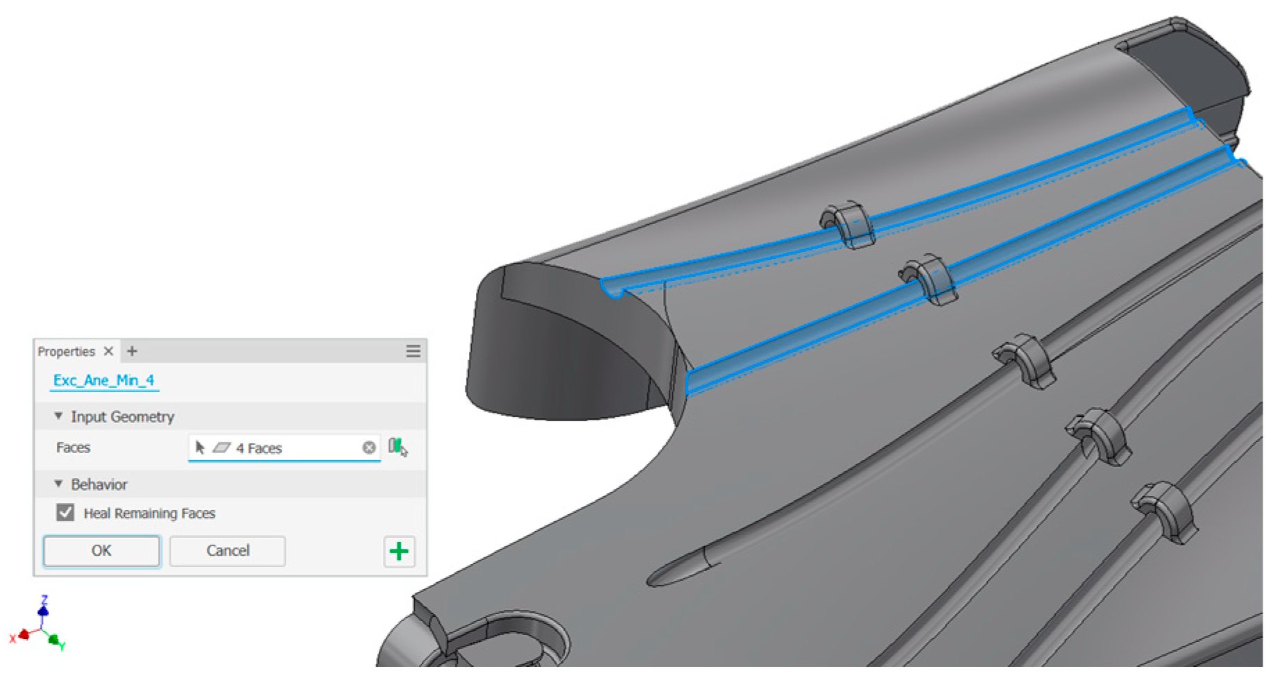
2.8. Parameterization Method by Suppression
2.9. Parameterization and Analysis of Level 3 Hand Amputation
2.10. Mechanical Feasibility Study
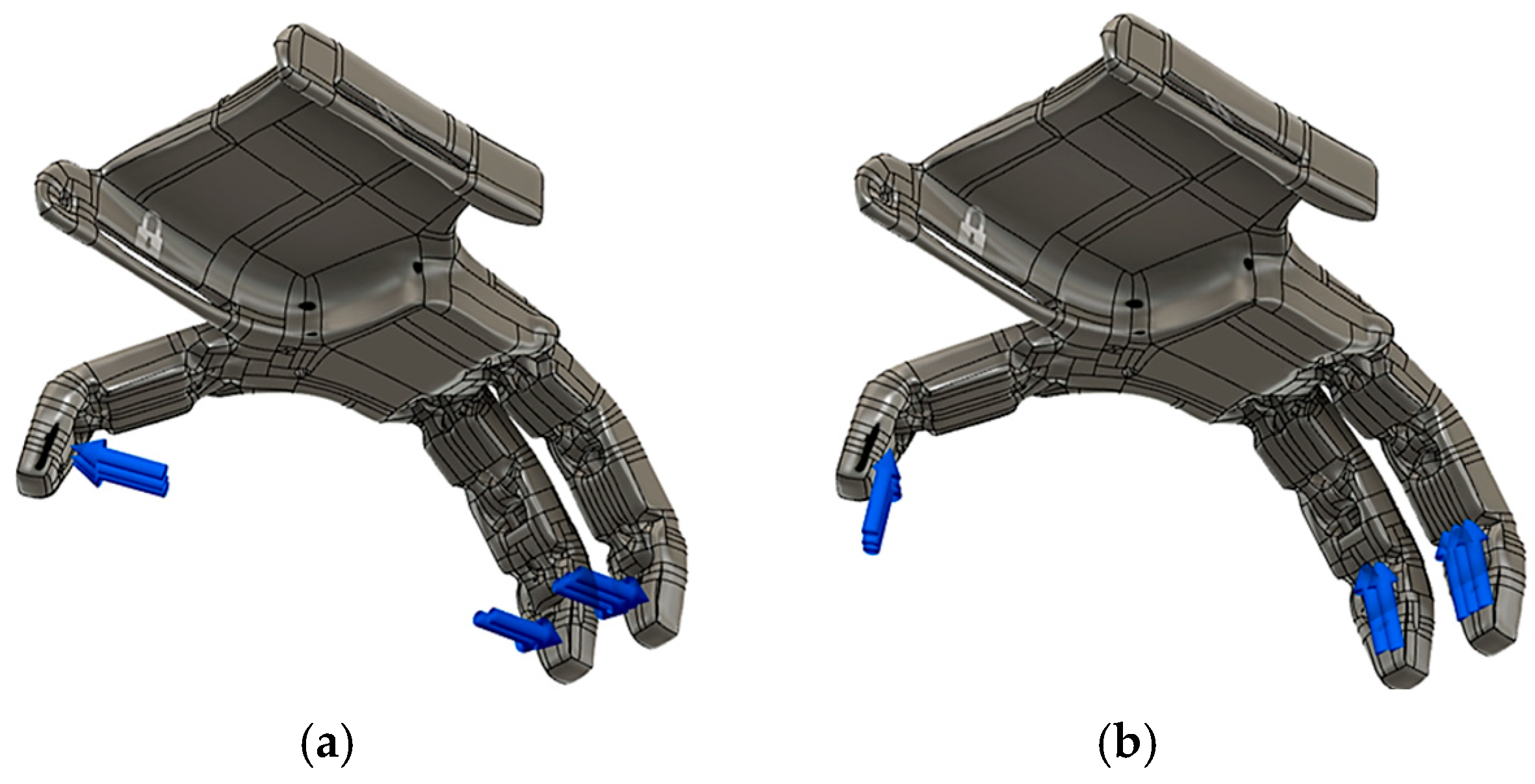
2.10.1. Boundary Conditions and Acting Forces
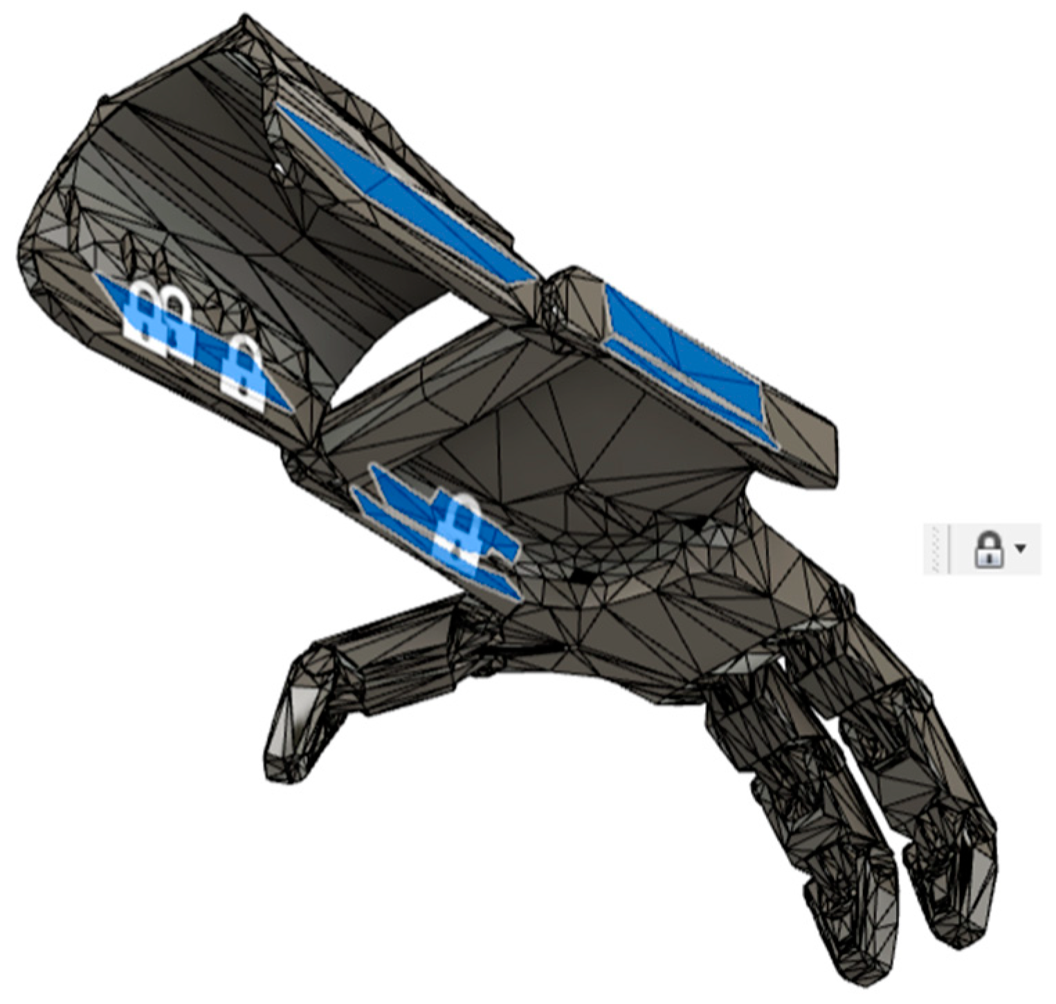
2.10.2. Boundary Constraints
3. Results and Discussion
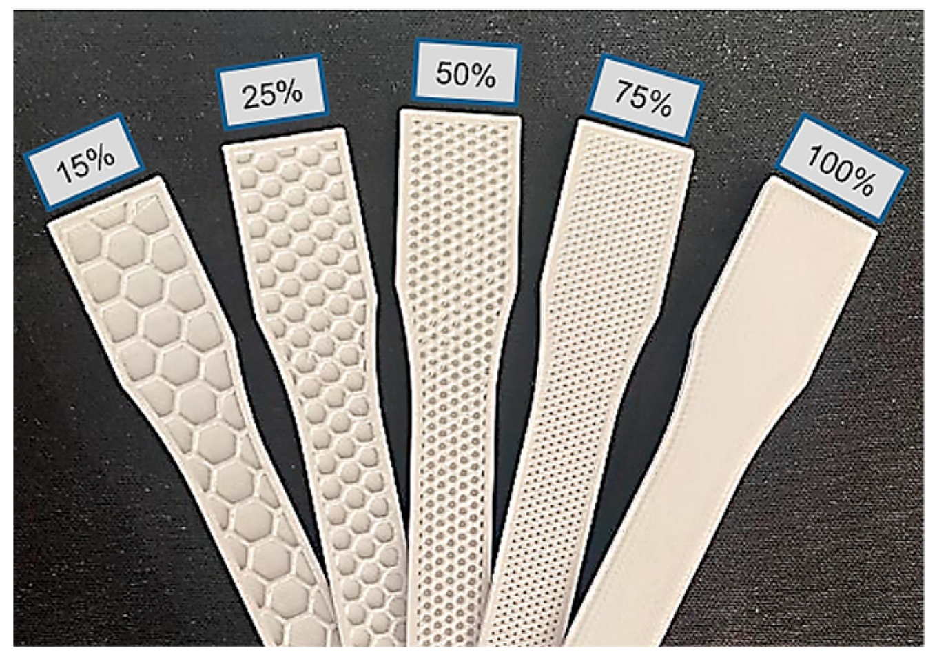
3.1. Specimen Measurements
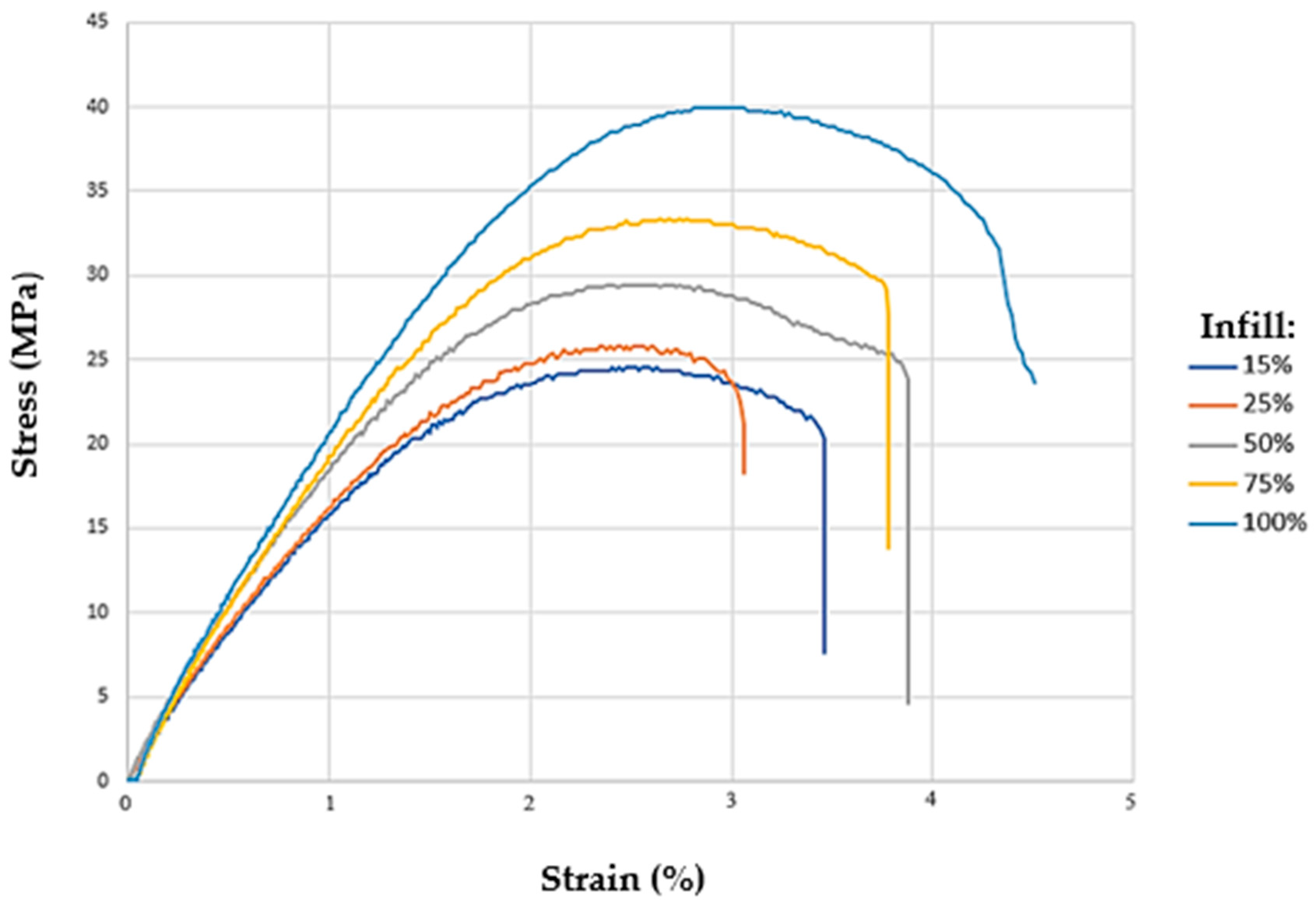
3.2. Tensile Test
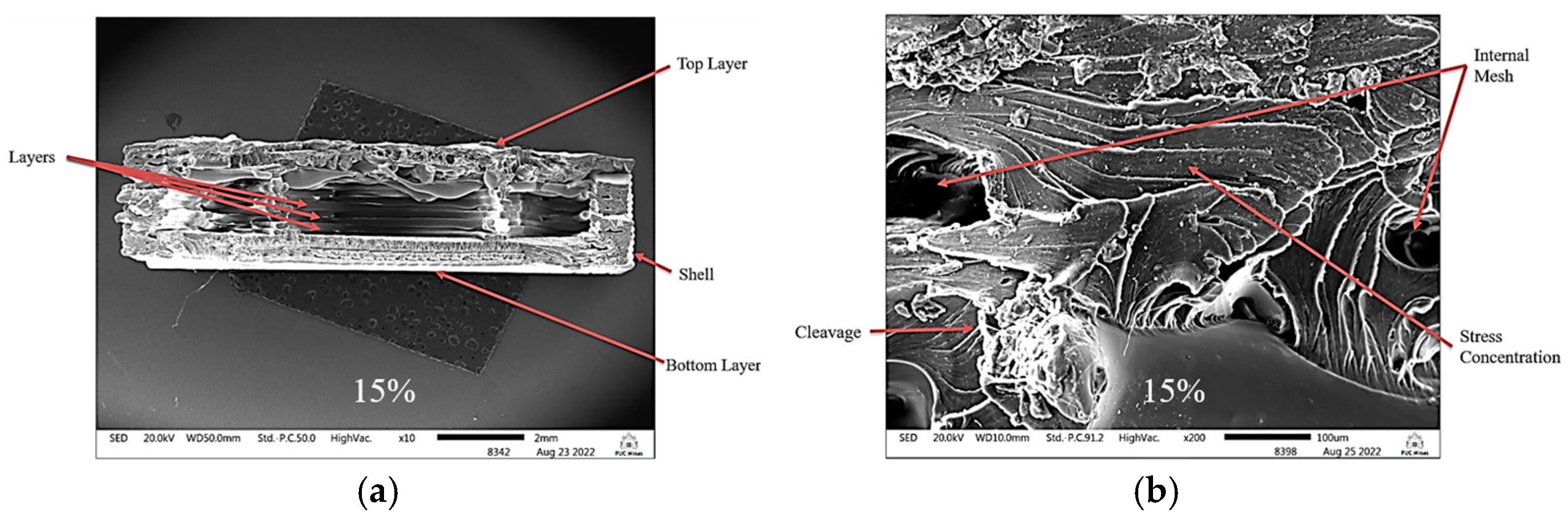
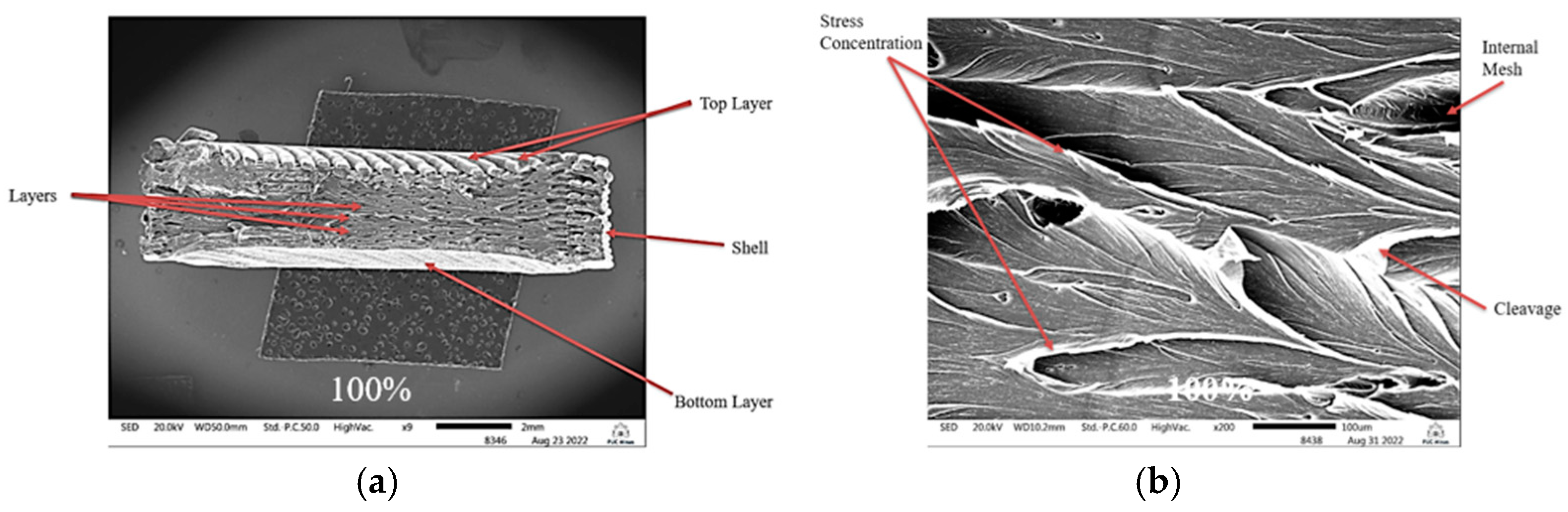
3.3. Scanning Electron Microscopy
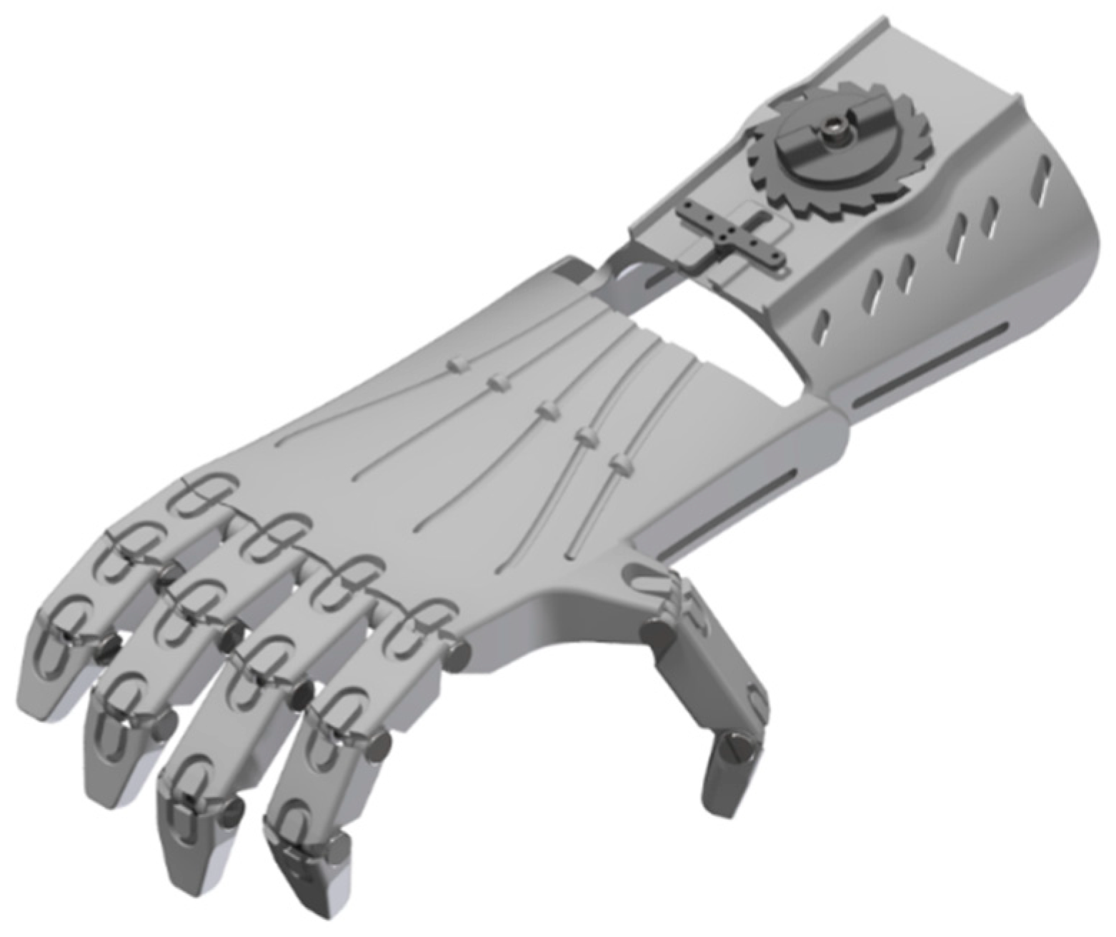
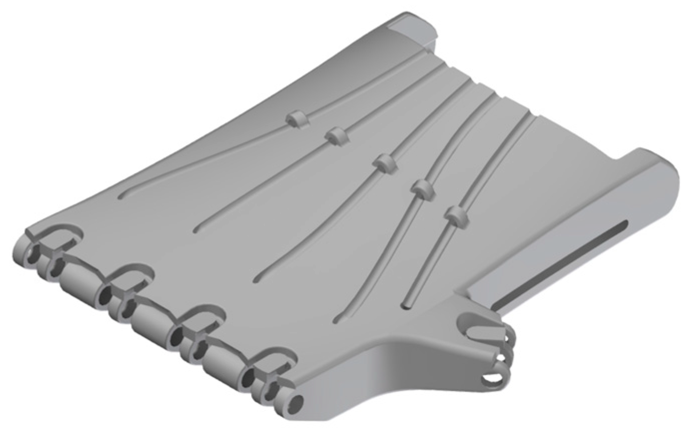
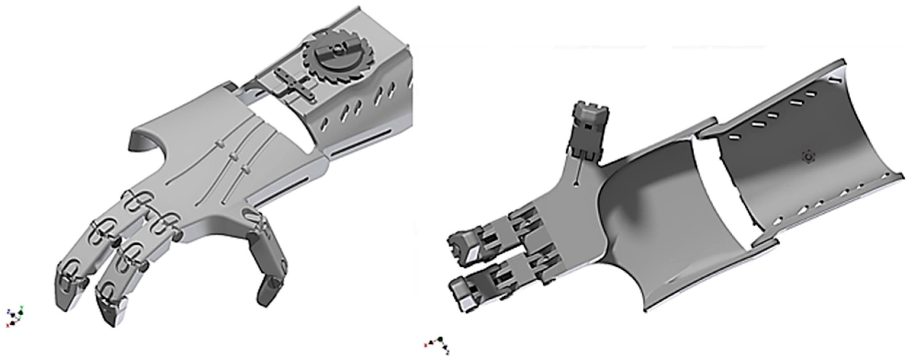
3.4. Three-Dimensional Model of the Generated Prosthesis
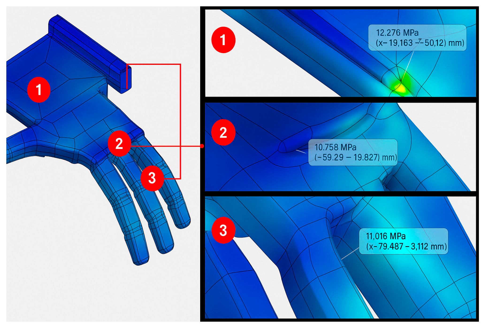
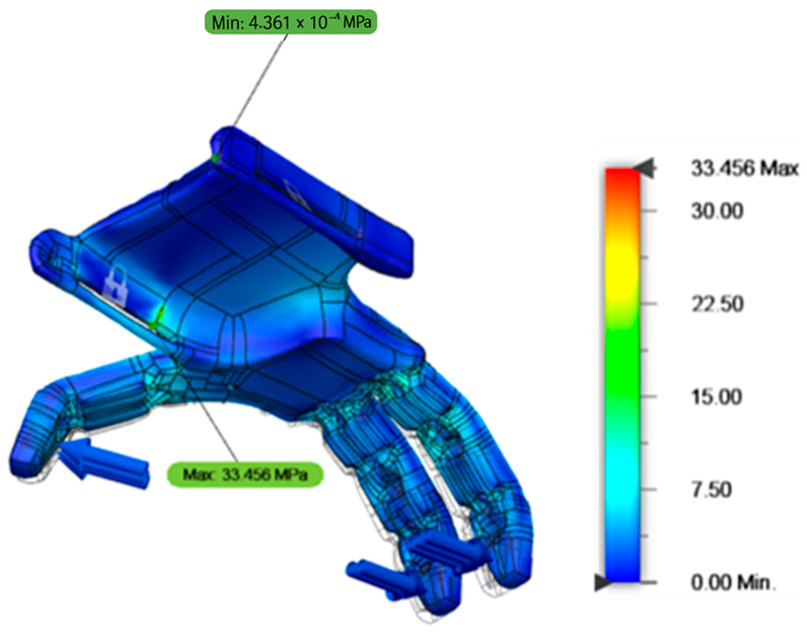
3.5. Stress Distribution
- Point 1—Lateral fixation region of the prosthesis: 12.276 MPa;
- Point 2—Metatarsophalangeal joint region of finger 2: 10.755 MPa;
- Point 3—Interphalangeal joint region (proximal/medial phalanx) of finger 3: 11.016 MPa.
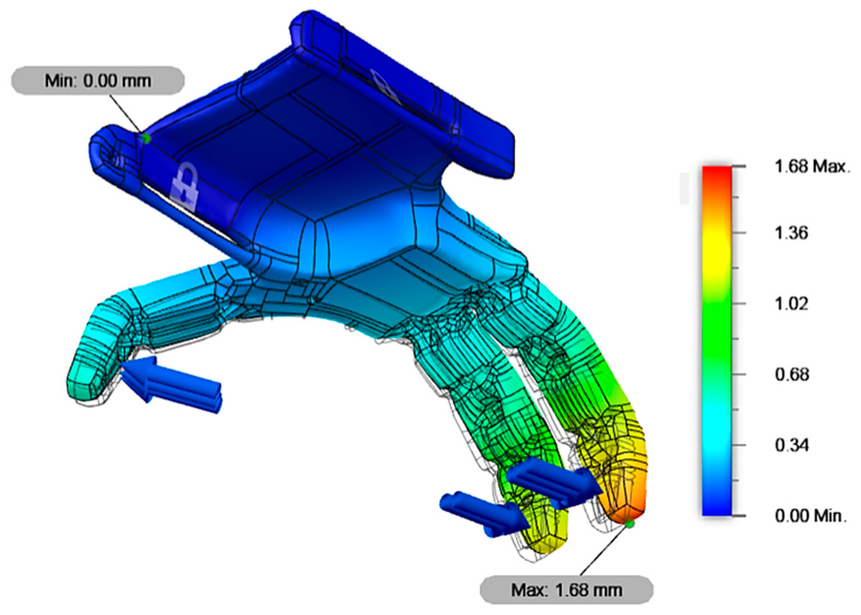
3.6. Displacement Distribution
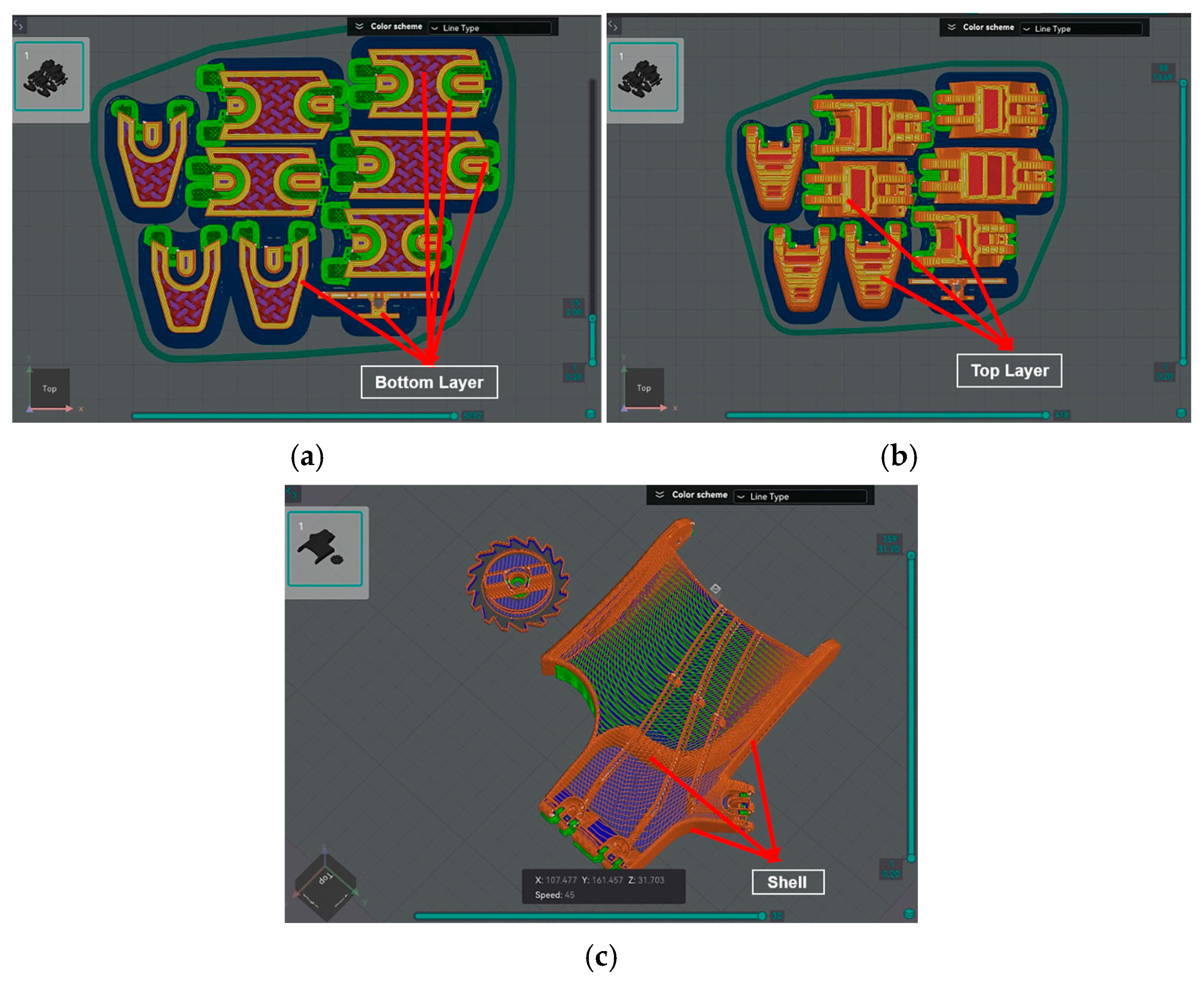
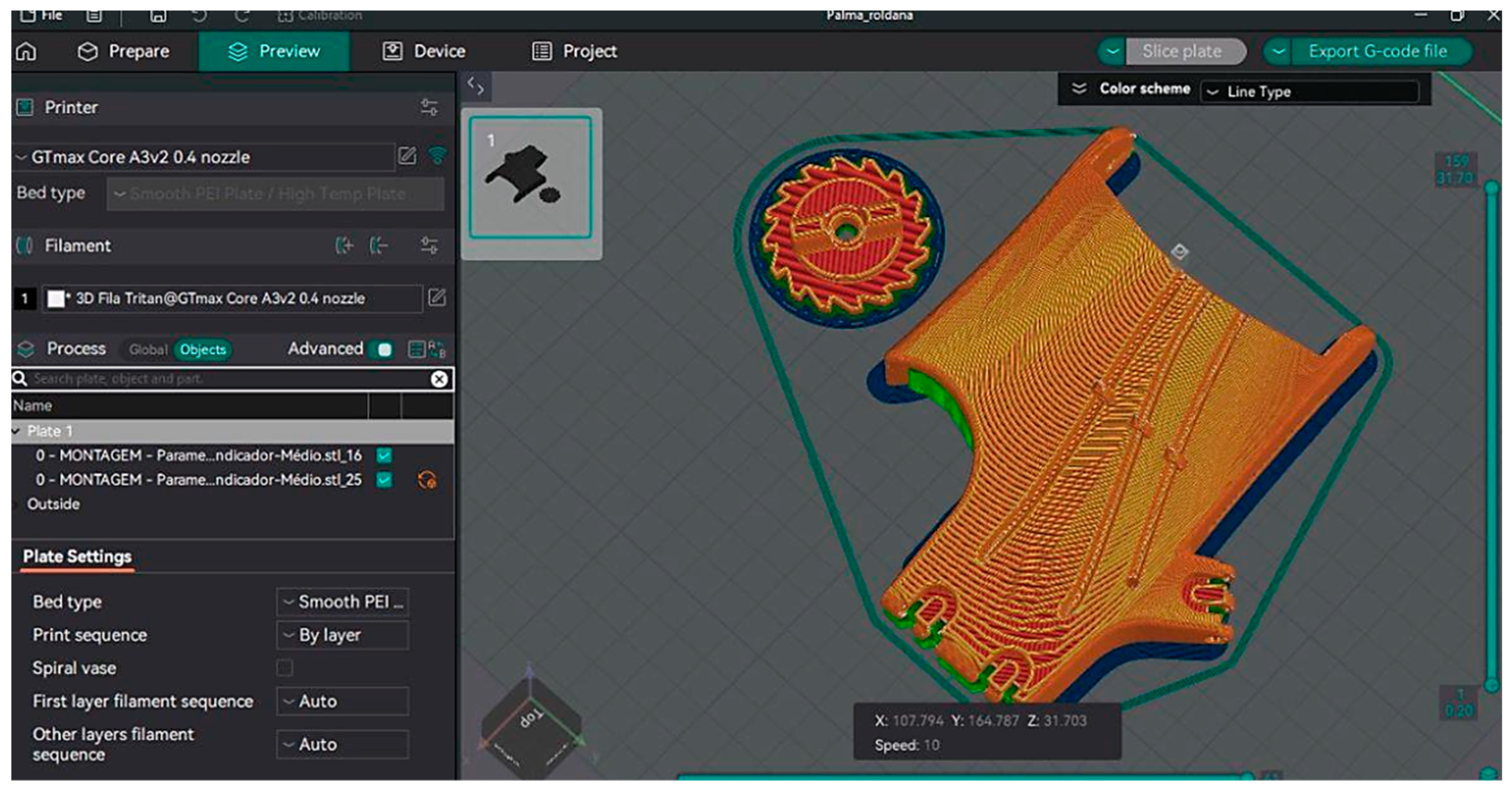
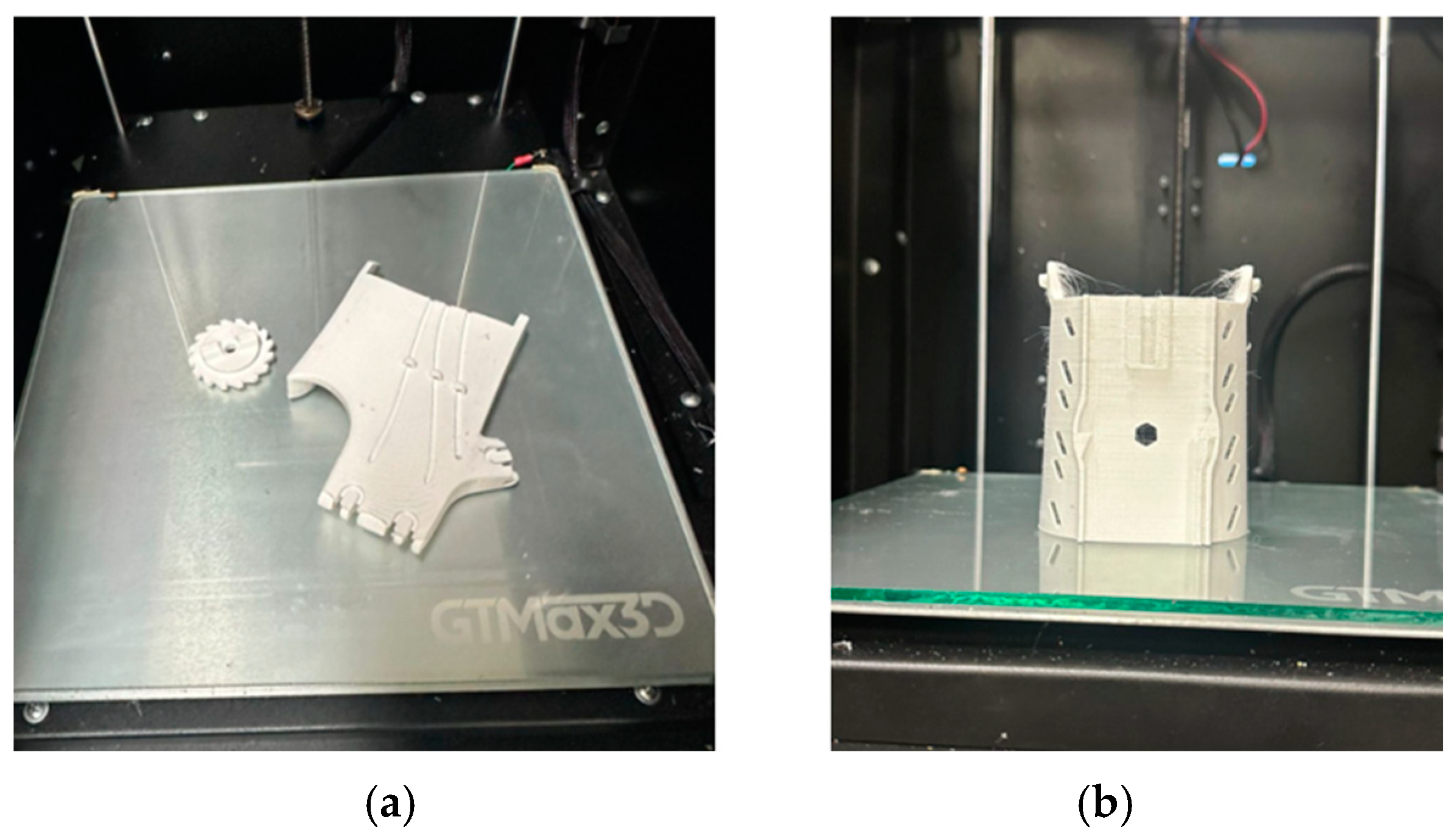
3.7. Device Printing
3.8. Device Building
4. Conclusions
Author Contributions
Funding
Institutional Review Board Statement
Informed Consent Statement
Data Availability Statement
Acknowledgments
Conflicts of Interest
References
- Hall, S.J. Biomecânica Básica; Guanabara Koogan: Rio de Janeiro, Brazil, 2016. [Google Scholar]
- Neumann, D.A. Cinesiologia do Aparalho Muscoesquelético; Guanabara Koogan: Rio de Janeiro, Brazil, 2018. [Google Scholar]
- Cordella, F.; Ciancio, A.L.; Sacchetti, R.; Davalli, A.; Cutti, A.G.; Guglielmelli, E.; Zollo, L. Literature review on needs of upper limb prosthesis users. Front. Neurosci 2016, 10, 209. [Google Scholar] [CrossRef] [PubMed]
- Zangrandi, A.; Alonzo, M.D.; Cipriani, C.; Pino, G.D. Neurophysiology of slip sensation and grip reaction: Insights for hand prosthesis control of slippage. J. Neurophysiol. 2021, 126, 477–492. [Google Scholar] [CrossRef]
- Williams, E.M.; Hatala, K.G.; Gordon, M.; Key, A.; Kasper, M.; Kivell, T.L. The manual pressures of stone tool behaviors and their implications for the evolution of the human hand. J. Hum. Evol. 2018, 119, 14–26. [Google Scholar] [CrossRef]
- Borthakur, P.P. The Role and Future Directions of 3D Printing in Custom Prosthetic Design. Eng. Proc. 2025, 81, 10. [Google Scholar] [CrossRef]
- Amarasinghe, A.G.C.S.; Chandrasri, N.K.U.K. Emerging Trends in Additive Manufacturing for Prosthesis Applications—A Review. J. Res. Technol. Eng. 2024, 5, 52–63. [Google Scholar]
- Kumar, M.; Krishnanand; Varshney, A.; Taufik, M. Hand prosthetics fabrication using additive manufacturing. Mater. Today Proc. 2024, 115, 36–45. [Google Scholar] [CrossRef]
- Savsani, S.; Singh, S.; Mali, H.S. Additive manufacturing for prostheses development: State of the art. Rapid Prototyp. J. 2022, 29, 741–765. [Google Scholar] [CrossRef]
- Deng, X.; Weirich, S.; Katzschmann, E.K.; Delbruck, T. A Rapid and Robust Tendon-Driven Robotic Hand for Human-Robot Interactions Playing Rock-Paper-Scissors. In Proceedings of the IEEE International Conference on Robot and Human Interactive Communication, Pasadena, CA, USA, 26–30 August 2024; Volume 33, pp. 2347–2354. [Google Scholar]
- Marinelli, A.; Boccardo, N.; Tessari, F.; Domenico, D.D.; Caserta, G.; Canepa, M.; Gini, G.; Barresi, G.; Laffranchi, M.; Michieli, L.D. Active upper limp prostheses: A review on current state and upcoming breakthroughs. Prog. Biomed. Eng. 2023, 5, 012001. [Google Scholar] [CrossRef]
- Huang, J.; Li, G.; Su, H.; Li, Z. Development and Continuous Control of an Intelligent Upper-Limb Neuroprosthesis for Reach and Grasp Motions Using Biological Signals. IEEE Trans. Syst. Man Cybern. Syst. 2022, 52, 3431–3441. [Google Scholar] [CrossRef]
- Beutel, B.G.; Gutowski, K.S.; Mitchelson, A.J.; Maender, C.W. Hand Amputation. National Library of Medicine. 2025. Available online: https://www.ncbi.nlm.nih.gov/books/NBK551692/ (accessed on 13 February 2025).
- Nayar, S.K.; Alcock, H.M.F.; Edwards, D.S. Primary amputation versus limb salvage in upper limb major trauma: A systematic review. Eur. J. Orthop. Surg. Traumatol. 2022, 32, 395–403. [Google Scholar] [CrossRef]
- Light, C.; Kyberd, P.J.; Chappel, P.H.; Naghtingale, L.M.; Whatley, D.; Evans, M. The design of anthropomorphic prosthetic hands: A study of the Southampton Hand. Robotic 2008, 19, 593–600. [Google Scholar]
- Gaballa, A.; Cavalcante, R.S.; Lamounier, E.; Soares, A. Extended Reality “X-Reality” for Prosthesis Training of Upper-Limb Amputees: A Review on Current and Future Clinical Potential. IEEE Transac. Neural Syst. Rehabil. Eng. 2022, 30, 1652–1663. [Google Scholar] [CrossRef] [PubMed]
- Salminger, S.; Stino, H.; Picher, L.H.; Gstoettner, C.; Sturma, A.; Mayer, J.A.; Aszmann, O.C. Currente rates of prosthetic usage in upper-limb amputees—Have innovations had an impact on device acceptance? Disabil. Rehabil. 2020, 44, 3708–3713. [Google Scholar] [CrossRef]
- Smail, L.C.; Neal, C.; Wilkins, C.; Packham, T.L. Comfort and function remain key factors in upper limb prosthetic abandonment: Findings of a scoping review. Disabil. Rehabil. Assist. Technol. 2020, 16, 821–830. [Google Scholar] [CrossRef] [PubMed]
- Catálogo 3D Fila. 2024. Available online: https://3dfila.com.br/produto/filamento-tritan-ht-blue-ocean/ (accessed on 3 May 2024).
- Owaidi, N.A.; Mora, M.C.; Ventura, S. Analysis on the Rejection and Device Passivity Problems with Myoeletric Prosthetic Hand Control. In Proceedings of the 28th World Multi-Conference on Systemics, Cybernetics and Informatics, Online, 10–13 September 2024. [Google Scholar] [CrossRef]
- Ministério da Saúde. Confecção e Manutenção de Órteses, Próteses, e Meios Auxiliares de Locomoção; Ministério da Saúde: Brasília, Brazil, 2022. [Google Scholar]
- Manual do Usuário GTMAX 3D. 2023. Available online: https://www.gtmax3d.com.br/impressora-3d-pro (accessed on 18 October 2023).
- ASTM D638; Standard Test Method for Tensile Properties of Plastics. American Society for Testing and Materials: West Conshohocken, PA, USA, 2022.
- ASTM 52921; Standard Terminology for Additive Manufacture Coordinate Systems and Test Methodologies. ASTM International: West Conshohocken, PA, USA, 2013.
- Knoop, F.; Schoeppner, V. Mechanical and thermal properties of FDM parts manufactured with polyamide 12. In Proceedings of the SFF Symposium, Austin, TX, USA, 10–12 August 2015; pp. 10–12. [Google Scholar]
- Santana, L.; Alves, J.L.; Netto, A.C.S.; Merlini, C. Estudo comparativo entre PETG e PLA para Impressão 3D através de caracterização térmica, química e mecânica. Rev. Matéria 2018, 23, 13–18. [Google Scholar] [CrossRef]
- Dias, W.S.; Otani, M.; Alves, T.S.; Bentes, C.W.; Silva, Y.W. The Influence of angulation on resistance to flexion and dimensional stability of printed resin in the SLA process for the development of a clamp for a robotic arm. Contemp. J. 2024, 4, 1–20. [Google Scholar]
- Gupta, V.K.; Srivastava, R. Experimental and FEA Studies of ABS Parts Produced by FDM Process. Int. J. Sci. Res. 2019, 30–36. [Google Scholar]
- Pecho, P.; Azaltovic, V.; Kandera, B.; Bugaj, M. Introduction study of design and layout of UAVs 3D printed wings in relation to optimal lightweight and load distribution. Transp. Res. Procedia 2019, 40, 861–868. [Google Scholar] [CrossRef]
- 3DLAB Filamento Tritan. 2024. Available online: https://3dlab.com.br/blog/ (accessed on 1 May 2024).
- Hibbeler, R.C. Mechanics of Materials; Pearson Education, Inc.: Upper Saddle River, NJ, USA, 2010. [Google Scholar]
- Huang, J.; Sun, Y.; Sun, C.; Chen, J. Experimental and finite element analysis on an elastic-plastic hemispherical asperity contact against a rigid flat in plane strain with bilinear hardening. Int. J. Appl. Mech. 2024, 17, 2430001. [Google Scholar] [CrossRef]
- Downey, R.J.; Hatzikiriaco, N.; Wang, Y. Hand fuction in Adults with Prosthetic Devices: A Biomechanical Analysis. J. Biomech. 2019, 45, 412–420. [Google Scholar]
- Harper, C.A.; Petrie, E.M. Plastics Materials and Processes: A Concise Encyclopedia; John Wiley & Sons, Inc.: Hoboken, NJ, USA, 2023. [Google Scholar]
- Mian, S.H.; Umer, U.; Moiduddin, K.; Alkhalefah, H. Finite Element Analysis of Upper Limb Splint Designs and Materials for 3D Printing. Polymers 2023, 15, 2993. [Google Scholar] [CrossRef] [PubMed]
- Mo, C.; Lyons, K.W.; Lam, C.; Neilsen, M.K. A Comparative Finite Element Stress Analysis Of Isotropic Matrix And 3D Printed PLA Material. In Proceedings of the International Conference On Technology and Science, Burdur, Türkiye, 14–16 November 2020. [Google Scholar]
- Chatterjee, A.; Rathore, V.; Bhattacharya, S. Finite Element Analysis Methodology for Additive Manufactured Components. Int. J. Eng. Technol. 2021, 14, 1–8. [Google Scholar]
- Xia, H.; Lu, H.; Liu, Z.; Jiang, Q. Isotropic and Anisotropic Elasticity and Yielding of 3D Printed Material. Compos. Part B Eng. 2017, 114, 41–48. [Google Scholar] [CrossRef]
- Romero, R.C.S.; Vimieiro, C.B.S.; Costa, K.A.; Reis, P.H.R.G.; Machado, A.A.; Brito, P.P. Development of a Passive Prosthetic Hand That Restores Finger Movements Made by Additive Manufacturing. Appl. Sci. 2020, 10, 4148. [Google Scholar] [CrossRef]
- Ossur Catálago de Próteses. 2024. Available online: https://www.ossur.com/pt-br (accessed on 28 May 2024).
- Ottobock Catálogo de Próteses. 2024. Available online: https://www.ottobock.com/en-ex/prostheses/prosthetic-arms-and-hands (accessed on 13 May 2024).


| Parameters | Value | Units |
|---|---|---|
| Printing Plan | YXZ | - |
| Infill | Tri-hexagonal | - |
| Speed | 40 | mm/s |
| Nozzle Temperature | 265 | °C |
| Bed Temperature | 110 | °C |
| Shell | 3 | perimeters |
| Layer Height | 0.2 | mm |
| Top Layer | 4 | mm |
| First Layer | 0.2 | mm |
| Group | Strain Maximum (MPa) | Yield Stress (MPa) | Modulus of Elasticity (MPa) |
|---|---|---|---|
| 1 (15%) | 24.52 ± 0.28 | 12.90 ± 0.89 | 322.53 ± 17.17 |
| 2 (25%) | 24.29 ± 0.22 | 13.79 ± 0.88 | 332.54 ± 7.76 |
| 3 (50%) | 30.10 ± 0.55 | 16.33 ± 0.71 | 370.73 ± 9.78 |
| 4 (75%) | 31.50 ± 0.22 | 18.86 ± 0.51 | 388.14 ± 18.72 |
| 5 (100%) | 39.42 ± 0.19 | 20.08 ± 0.86 | 426.70 ± 16.62 |
Disclaimer/Publisher’s Note: The statements, opinions and data contained in all publications are solely those of the individual author(s) and contributor(s) and not of MDPI and/or the editor(s). MDPI and/or the editor(s) disclaim responsibility for any injury to people or property resulting from any ideas, methods, instructions or products referred to in the content. |
© 2025 by the authors. Licensee MDPI, Basel, Switzerland. This article is an open access article distributed under the terms and conditions of the Creative Commons Attribution (CC BY) license (https://creativecommons.org/licenses/by/4.0/).
Share and Cite
da Silveira Romero, R.C.; Costa, K.A.; Reis, P.H.R.G.; Vimieiro, C.B.S. Development of Parametric Prostheses for Different Levels of Human Hand Amputations Manufactured Through Additive Manufacturing. Appl. Sci. 2025, 15, 4467. https://doi.org/10.3390/app15084467
da Silveira Romero RC, Costa KA, Reis PHRG, Vimieiro CBS. Development of Parametric Prostheses for Different Levels of Human Hand Amputations Manufactured Through Additive Manufacturing. Applied Sciences. 2025; 15(8):4467. https://doi.org/10.3390/app15084467
Chicago/Turabian Styleda Silveira Romero, Rodrigo Cézar, Kliftom Amorim Costa, Paulo Henrique Rodriguês Guilherme Reis, and Claysson Bruno Santos Vimieiro. 2025. "Development of Parametric Prostheses for Different Levels of Human Hand Amputations Manufactured Through Additive Manufacturing" Applied Sciences 15, no. 8: 4467. https://doi.org/10.3390/app15084467
APA Styleda Silveira Romero, R. C., Costa, K. A., Reis, P. H. R. G., & Vimieiro, C. B. S. (2025). Development of Parametric Prostheses for Different Levels of Human Hand Amputations Manufactured Through Additive Manufacturing. Applied Sciences, 15(8), 4467. https://doi.org/10.3390/app15084467