Article

A Strength–Permeability Study of Steel Slag–Cement–Bentonite Barrier Walls Effect of Slag Substitution Rate and Bentonite Dosage

1
Jiangsu Province Engineering Research Center of Geoenvironmental Disaster Prevention and Remediation, School of Architecture and Civil Engineering, Jiangsu University of Science and Technology, Zhenjiang 212100, China
2
School of Civil Engineering, Suzhou University of Science and Technology, Suzhou 215009, China
*
Author to whom correspondence should be addressed.
Appl. Sci. 2025, 15(8), 4544; https://doi.org/10.3390/app15084544
Submission received: 17 March 2025 / Revised: 15 April 2025 / Accepted: 17 April 2025 / Published: 20 April 2025
(This article belongs to the Special Issue Advanced Technologies in Landfills)

Abstract

:
A barrier wall is a vertical engineered layer designed to block contaminated soil, thereby controlling pollution sources, preventing pollutant migration to groundwater, and limiting pollution spread. Cement–bentonite barrier walls, widely adopted for their seepage control capability, structural strength, and cost-effectiveness, face sustainability challenges due to high cement consumption. This study systematically investigates the coupled effects of steel slag substitution rate and bentonite dosage on the mechanical–permeability of barrier materials for the first time and proposes steel slag (containing dicalcium silicate (C2S) and tricalcium silicate (C3S) phases similar to cement clinker) as a partial cement substitute in steel slag–cement–bentonite barrier materials, aiming to reduce cement usage and utilize industrial waste. Through unconfined compressive strength tests, direct shear tests, and variable head permeability tests, the effects of steel slag substitution rates (0~50%) and bentonite dosages (46~54%) on material performance were systematically investigated. Key findings include (1) unconfined compressive strength decreases linearly with increasing steel slag substitution but grows exponentially with bentonite dosage; (2) cohesion exhibits a negative exponential relationship with steel slag substitution and a linear positive correlation with bentonite content—the unconfined compressive strength of the materials with bentonite dosage of 50% and 54% were 1.51 and 2.84 times higher than those with bentonite dosage of 46%, respectively; (3) cohesion and unconfined compressive strength conform to c = (0.23~0.39)qu; (4) permeability decreases with higher steel slag substitution and bentonite dosage, achieving controlled low permeability (<1 × 10⁻⁷ cm/s). This research provides a sustainable solution for barrier wall construction by integrating waste recycling and performance optimization.

1. Introduction

With the rapid economic development around the world, environmental issues have become increasingly severe. Municipal waste and industrial pollution all cause a series of site pollution events. This not only leads to the deterioration of soil and water environments but also seriously threatens the aquatic environment and human health, which has attracted widespread attention worldwide [1,2].
Groundwater pollution interception technology is a commonly used risk management program for groundwater-contaminated sites [3]. This technology is mainly based on the environment of the contaminated site, topography, geological conditions, and other reasonable selections of anti-seepage and pollution intercepting performance of the material poured into the wall to build a vertical engineered barrier (vertical engineered barrier). Various types of barriers beyond cement–bentonite barrier walls also have a short construction period. Moreover, the seepage control effect is obvious, and the cement–bentonite barrier wall has better applicability due to the hydration of cement, so the slurry has a stronger cementing effect, meaning it has relatively high strength and can better control the deformation.
At present, in foreign research on cement–bentonite barrier wall materials in the cement replacement material, such as in the United Kingdom’s barrier wall project, fly ash or finely ground blast furnace slag used as part of the cement replacement material can often improve the barrier wall impermeability and resistance to water secretion. Reducing the cost of construction at the same time also solved the problem of slag utilization; thus, environmental protection and economic benefits are realized [4,5,6]. Steel slag is a solid waste discharged in the steelmaking process, and its emissions account for 15% to 20% of crude steel production [7]. Iron and steel are the basic industries of China’s national economy; the emissions from steel slag have increased since 2003; China’s emissions from steel slag production are about 0.8 to 120 million tons [8]. Global annual production of steel slag is about 300 million tons, with China accounting for about 40%. The steel slag–cement–bentonite barrier wall made by replacing part of the cement with steel slag can also achieve the same purpose as in the UK barrier wall project. The results of the study showed that steel slag powder can stimulate the higher activity of steel slag powder in a certain range of fineness, which is well adapted to the cement and can improve the late strength and durability of concrete [9]. Taking into account the economy and practicality of steel slag and combining it with environmental characteristics, we present our study in this paper.
Barrier wall in service by the environment and other external factors, as well as changes in the water level on both sides, will change the lateral earth pressure of the barrier wall, resulting in excessive deformation and cracking of the hardened barrier wall, and then the pollutants can easily migrate from the polluted area so that the barrier wall impermeability is lost. The unconfined compressive strength and, especially, the permeability coefficient are important indicators for evaluating the quality during the design process of the barrier wall.
The chemical and mineralogical composition of steel slag is similar to cement [10], the use of steel slag as a cementitious material is the current hotspot of the research on steel slag [11]. Altun et al. [12] pointed out that the effective use of industrial waste products (e.g., fly ash, granulated blast furnace slag powder, steel slag powder) as a supplementary cementitious material has become a major trend in concrete technology. Kriskova et al. [4] studied the hydration properties of AOD and LM, two kinds of steel slag, and found that the 90d strength of steel slag can reach 10% and 20% of the cement, respectively, and its strength is related to the water-to-binder ratio, which shows that steel slag can be used as cementitious materials.
Opdyke et al. [5], in order to verify the effect of the content of cementitious materials on the strength, the test showed that the greater the proportion of cementitious materials, the greater the unconfined compressive strength of the soil samples when the proportion of cementitious materials for the proportion of 20%, the unconfined compressive strength of soil samples of the 28d can be up to 365 kPa. Kourounis et al. [13] investigated the effect of steel slag on the hydration properties of cement. Steel slag, sharing comparable chemical compositions with cement, demonstrates activated cementitious properties through physical grinding or chemical activation. Its cementitious components participate in hydration reactions to form products such as ettringite (AFt), while inert components optimize pore structure through physical filling. When combined with cement, steel slag delays early-stage hydration (by reducing AFt formation and inhibiting C-S-H growth), enhancing strength development, and found that the admixture of steel slag retarded the hydration reaction of cement and the compressive strength of steel slag cement with standard curing for 90d was lower than the compressive strength of pure cement.
Many scholars in China have also studied the properties of cement–bentonite slurry materials through various theories and tests. The net-like structure in bentonite can inhibit its effective expansion, and also inhibit the drying shrinkage of cement, effectively preventing the intrusion of harmful leachate. Ding Guoqing et al. [14] showed that increasing the dosage of bentonite reduces the content of Ca2+ while the porosity of the cement paste is reduced. Chen Lu [15] combined with Wuhan Tiandi, Yulong Plaza, and other foundation pit support projects through indoor tests, obtained the cement—fly ash—bentonite different mixing ratios on the compressive strength and shear strength. The test showed that the same ratio of cement soil unconfined compressive strength and cohesion ages and increases with bentonite dosages of 5% to 11%, a fly ash dosage in the range of 20–30, and maintenance of an unconfined compressive strength of 28d soil sample reaching 7 MPa.
Wang et al. [16], in order to study the interaction between the erodibility of damaged seepage barriers and cementitious materials and water flow based on indoor pinhole erosion tests, calculated the percentage of erosion and established the relationship with the age of curing, erosion time, and the size of the initial hole. The results indicate that the curing time affects the hydraulic conductivity in the macro-structure of the barrier; the growth of the erosion time, the material erodes quickly at the initial erosion rate, then slows down, and finally tends to a stable state; the different erosion conditions during the curing period are affected by the size of the initial hole. It is concluded from the study that the cement–bentonite material is optimized when the bentonite dosage is 18%.
In this study, multiple sets of parallel specimens were prepared to systematically investigate the influence of steel slag substitution rates and bentonite dosage on the mechanical and hydraulic properties of barrier materials. Unconfined compressive strength tests, direct shear tests, and variable head permeability tests were conducted to quantify the variations in compressive strength, cohesion, and permeability coefficients. But for the high-bentonite content system in the lesser described situation, this paper, in addition to investigating steel slag to improve the bentonite environment (46–54%), also makes up for the low-bentonite content system of some problems. Furthermore, the correlation between cohesion and unconfined compressive strength was analyzed to establish an empirical relationship. The experimental design aimed to elucidate the governing laws of parameter interactions under controlled conditions.

2. Materials and Methods

2.1. Test Materials

This section briefly describes the physicochemical properties of materials, mix design, and experimental methodologies. The particle size distributions (Figure 1) and chemical compositions of bentonite, cement, and steel slag were determined using a laser particle sizer (Mastersizer 2000. The instrument is manufactured in Nanjing, China) and X-ray fluorescence spectroscopy. These data underpin the analysis of mechanical and permeability performance. All tests followed the Standard for Geotechnical Test Methods (GB/T50123-2019) and ASTM specifications to ensure reproducibility and engineering relevance.
The test was conducted using a yellowish-white powder, which was bentonite produced by Suzhou Jiegao, and the particle size of the material can be seen in Figure 1. According to the soil classification system [17], this bentonite belongs to high-liquidity clay. The chemical composition of bentonite is shown in Table 1, and the basic physical index of bentonite is shown in Table 2.
The cement used in the test of this paper is 42.5-grade ordinary silicate cement. The chemical composition of the cement was analyzed using X-ray fluorescence spectrometer; the chemical composition is shown in Table 3, and the main performance indexes are shown in Table 4.
We tested steel slag from a steel mill in Henan, which came in the form of a grey powder (200–400 mesh). In reference to the determination of bentonite particle size distribution method, a laser particle sizer, Mastersizer 2000, measured the particle size distribution of steel slag powder, as shown in Figure 1. The chemical composition is shown in Table 5.
The formula for calculating the alkalinity of steel slag is shown in Equation (1). This equation can be used to calculate the steel slag alkalinity in this study. Mason [18] classified the alkalinity of steel slag, and the relationship between the alkalinity of steel slag and its mineral composition is shown in Table 6. The alkalinity of steel slag can evaluate the activity of steel slag, and greater activity corresponds to higher alkalinity [19]. The alkalinity of the steel slag used in this study is calculated as 1.68, which falls under the dicalcium silicate slag category according to the classification.
P = CaO/(SiO2 + P2O5)

2.2. Preparation of Samples

2.2.1. Mix Design

In the proportioning test, mainly, the effects of steel slag substitution rate and bentonite dosage on the strength properties of barrier materials were considered. In the case of a certain water-to-binder ratio (Rw/b = 6.25), the configuration of five kinds of steel slag substitution rates Rs (the ratio of steel slag mass to the composite cementitious material) and three kinds of bentonite dosages RB (the ratio of bentonite mass to the total mass of the solids) of the steel slag–cement–bentonite soil samples at different curing ages were used to study the effect of different ratios and ages on its strength properties.
Definitions are shown in Equations (2)–(4):
Rw/b = mw/(ms + mc)
Rs = ms/(ms + mc)
RB = mB/(ms + mc + mB)
where mw is the mass of water (g); ms is the mass of steel slag (g); mc is the mass of cement (g); mB is the mass of bentonite (g); Rs is the substitution rate of steel slag (%); and RB is the dosage of bentonite (%).
Through pre-design tests and reading of the related literature [20,21], the total amount of 750 g of water, cement, and steel slag was 120 g, i.e., the water-to-binder ratio was 6.25 and the steel slag substitution rate was 0, 12.5%, 25%, 37.5%, 50%. Bentonite dosage in 100 g, 120 g, 140 g, i.e., bentonite admixture in 46%, 50%, 54%. The specific proportioning scheme is shown in Table 7.
A total of 15 proportioning schemes, each proportion of the production of nine internal diameters of 39.1 mm with height of 80 mm soil samples, respectively, for the determination of age 7d, 14d, 28d unconfined compressive strength, was used in order to avoid test errors, and each design used three parallel sample ages.

2.2.2. Methods of Sample Preparation

Steel slag–cement–bentonite barrier material test block production is as follows: ① Dosing and Mixing: Using an electronic balance, accurately weigh deionized water and bentonite clay and mix until a homogeneous slurry is formed with no visible particles. ② Adding Cementitious Materials: Add precisely measured quantities of cement and steel slag to the bentonite slurry and mix to ensure that no particles are visible. ③ Forming and compaction: the homogenized mixture is poured into a Vaseline-coated cylindrical mold in three equal layers. Each layer was mechanically vibrated to eliminate entrained air. The final layer was smoothed with a stainless steel trowel in accordance with ASTM Specification C617/C617M-15 [22]. ④ Curing Molding: The demolded specimens were transferred to a curing chamber (20 ± 2 °C, 98% RH) conforming to ASTM C511-21 (Standard Specification for Mixing Chambers, Moisture Cabinets, Moisture Chambers, and Tanks Used in the Testing of Hydraulic Cement and Concrete).

2.3. Test Methods

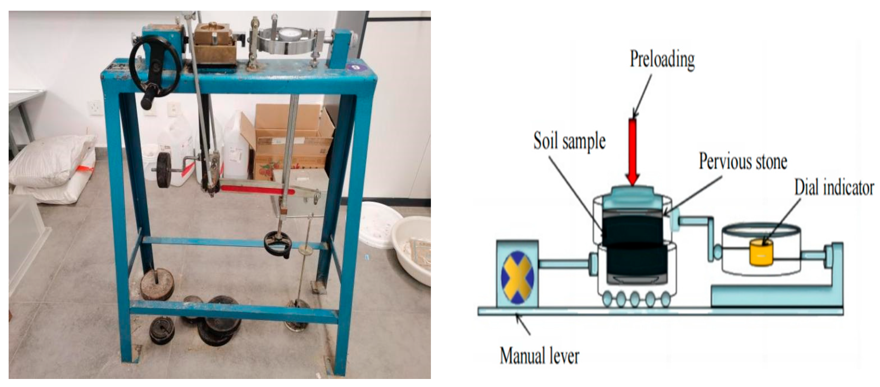
2.3.1. Unconfined Compressive Strength Test

Determining the unconfined compressive strength of the barrier material can provide reference for its application in engineering; this paper’s unconfined compressive strength test apparatus adopted fully automatic data acquisition, and the unconfined compressive apparatus was produced by Nanjing Soil Instrument Co., Ltd. in Nanjing, China.
In this paper, the unconfined compressive strength test was conducted in accordance with the Standard for Geotechnical Test Methods (GB/T50123-2019) [23]. According to the specification of soil sample height and soil sample diameter ratio should be in the range of 2.0~2.5, the height of the test soil sample should be 80 mm, the diameter should be 39.1 mm. First of all, according to Section 2.2.2 of this paper, which details the sample preparation method, the soil sample should be in the center of the base of the unconfined compression tester. The height of the base was adjusted to the point where the soil sample was just in contact with the upper axial force sensor, and then the readings of the axial force sensor and the displacement sensor were zeroed, the deformation was set to 12 mm, and the strain rate was 1 mm/min according to the time of acquisition. The load was applied at a uniform speed, and finally, the stress–strain data were collected through the system that comes with the unconfined compression tester, and the readings were stopped after the peak, and the load readings were stabilized. Three parallel specimens were taken for each proportioning test at each age, and the test results were read at the end of the test.

2.3.2. Direct Shear Test

Using direct shear test device from Nanjing Ningxi Soil Instrument Co., Ltd., a production of ZJ-2 type equal strain direct shear instrument, as shown in Figure 2, the shear mode of this test for the unconsolidated undrained shear was set, with a shear rate set to 0.8 mm/min, maximum shear displacement set to 4 mm~6 mm, shear time of 5 min~7 min. The vertical load was divided into four load levels: 25 kPa, 50 kPa, 50 kPa, 100 kPa, 200 kPa.
Direct shear test was conducted in accordance with the Standard for Geotechnical Test Methods (GB/T50123-2019) [23]. The height of the soil sample was 20 mm, the inner diameter was 61.8 mm, and the cross-sectional area was 30 cm2. If the per centimeter reading continues to increase during the test, stop shearing when the shear displacement is 6 mm and take the corresponding shear stress when the shear displacement is 4 mm for the shear strength. At the end of the test, unload and pressurize the transfer bar, let the shear box return to its original position, open the shear box, and take out the damaged soil sample. The test data were processed to find out the values of c and φ.
Formula
The shear stress shall be calculated according to Equation (5).
τ = 10CR/A0
where τ is the shear stress (kPa), C is the force gauge factor (N/0.01 mm), R is the force gauge reading (0.01 mm), A0 is the shear area (cm2), and 10 is the unit conversion factor.

2.3.3. Variable Head Permeability Test

The infiltration test was carried out through the variable head infiltrometer, a total of 15 proportioning schemes; each proportion of the production contains three samples. Firstly, the soil sample was maintained in the conservation box for 3d until the soil sample was shaped; then, the soil sample was taken out and loaded into the variable head infiltrometer. Then, water was injected into the variable head pipe, and air bubbles were discharged from the instrument through the control valve. And when the water overflowed from the outlet, the initial height and the initial time in the variable head pipe were measured. After that, the height of the head pipe was changed, and when the water level was stabilized, the measurement of the water level and the time of the changes were repeated 5 to 6 times, removing the results with large errors and taking the average value. Tests were conducted at ages 7d, 14d, and 28d, respectively.
Calculate the permeability coefficient according to Equation (6).
k = 2.3 a L A t log Δ h 1 Δ h 2 t = t 2 t 1
where a is the cross-sectional area of the graduated tube (mm2); L is the height of the soil sample (mm); A is the cross-sectional area of the soil sample (mm2); and t is the time difference (s). Δh1, t1 and Δh2, t2 represent the amount of change in head height and initial and final head heights, respectively.

3. Results

3.1. Study on the Unconfined Compressive Strength of Steel Slag–Cement–Bentonite Barrier Materials

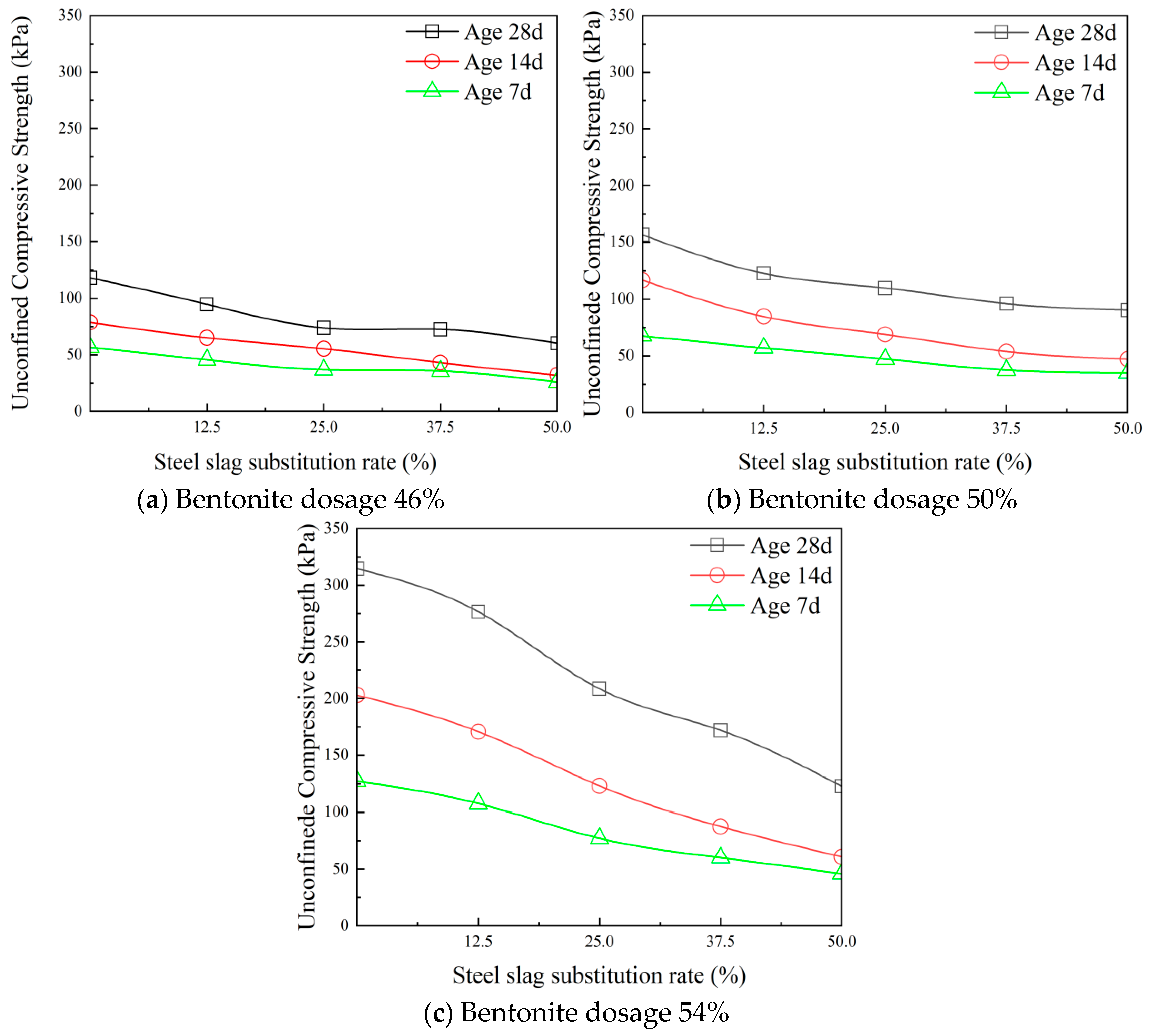
3.1.1. Effect of Steel Slag Substitution Rate on the Unconfined Compressive Strength of Barrier Materials

In Figure 3a–c, the steel slag–cement–bentonite barrier material with a steel slag substitution rate at different ages and bentonite dosages of 46%, 50%, and 54%, respectively, are shown. In Figure 3a–c, it can be seen that the unconfined compressive strength of steel slag–cement–bentonite barrier material decreases gradually with the increase in steel slag substitution rate at the same age and the same bentonite dosage. Figure 3a illustrates that when the bentonite dosage is 46% and the steel slag substitution rate is 0, 12.5%, 25%, 37.5%, and 50%, the unconfined compressive strength of the material at the age of 28 d is 117.94 kPa, 93.99 kPa, 72.80 kPa, 69.38 kPa, and 58.18 kPa, respectively. The steel slag substitution rates in this data set are 0, 12.5%, 25%, and 37.5%, which are 2.027, 1.615, 1.251, and 1.192 times the unconfined compressive strength of steel slag substitution rate of 50%, respectively, and the unconfined compressive strength of the material gradually decreases. Similarly, in Figure 3b,c with the bentonite dosage changes, the age remains the same, and the steel slag–cement–bentonite barrier material unconfined compressive strength still increases with the rate of steel slag substitution and presents the phenomenon of gradual reduction.

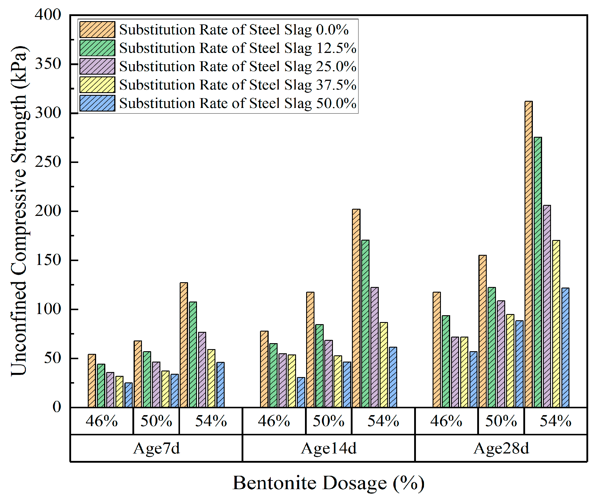
3.1.2. Effect of Bentonite Dosage on the Unconfined Compressive Strength of Barrier Materials

In Figure 4, the unconfined compressive strength increases with the bentonite dosage at the same steel slag substitution rate and age. For example, the unconfined compressive strength of steel slag–cement–bentonite barrier materials with an age of 28d, a steel slag substitution rate of 25%, and bentonite dosages of 46%, 50%, and 54% were 72.80 kPa, 109.66 kPa, and 206.93 kPa, respectively. The larger the bentonite dosage, the more the pores of the cement skeleton in the steel slag–cement–bentonite slurry are filled, and the other part reacts with the cement steel slag and becomes part of the overall structure. With the increase in bentonite, as more pores of the cement skeleton are filled, the strength increases.

3.2. Study on Shear Strength of Steel Slag–Cement–Bentonite Barrier Material

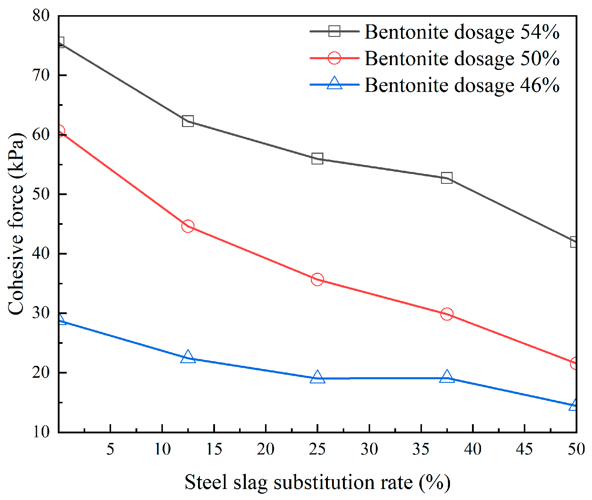
3.2.1. Effect of Steel Slag Substitution Rate on the Cohesion of Barrier Materials

In the barrier wall construction process, especially in contaminated sites and the context of mountain slopes, the barrier wall not only assumes the role of seepage control but also needs to assume shear strength; the weak parts of the wall are likely to lead to the site destabilization and damage; therefore, the design process of the barrier wall should be taken into account when considering the shear strength indicators (angle of internal friction and cohesion) in order to improve the overall stability and load-bearing capacity. Considering the long-term service life of the barrier wall in the actual project, this subsection will focus on the cohesion of the steel slag–cement–bentonite barrier material after 28d of maintenance under different bentonite dosages and different steel slag substitution rates.
Figure 5 shows the relationship between the cohesion and steel slag substitution rate under different bentonite dosages, in which, no matter the bentonite dosage, the cohesion of the material is slightly and gradually reduced with the increase in the steel slag substitution rate. When the bentonite dosage is 46% and the steel slag substitution rate changes from 0 to 50%, the decrease in cohesion is 6.46 kPa, 3.30 kPa, 0.06 kPa, and 4.61 kPa, respectively, and when the bentonite dosage is 50% and the steel slag substitution rate changes from 0 to 50%, the decrease in cohesion is 15.34 kPa, 8.97 kPa, 5.93 kPa, and 8.33 kPa, respectively. When the bentonite dosage is 54% and the steel slag substitution rate is changed from 0 to 50%, the decrease in cohesion is 13.17 kPa, 6.22 kPa, 3.46 kPa, 10.88 kPa. At the same bentonite dosage, the material’s cohesion decreases sharply when the steel slag substitution rate is increased from 0 to 12.5%, and the lowest decrease in cohesion occurs when the steel slag substitution rate is increased from 25% to 37.5%. When the steel slag substitution rate was increased from 25% to 37.5%, the decrease in cohesion was the least and even an increase was observed.

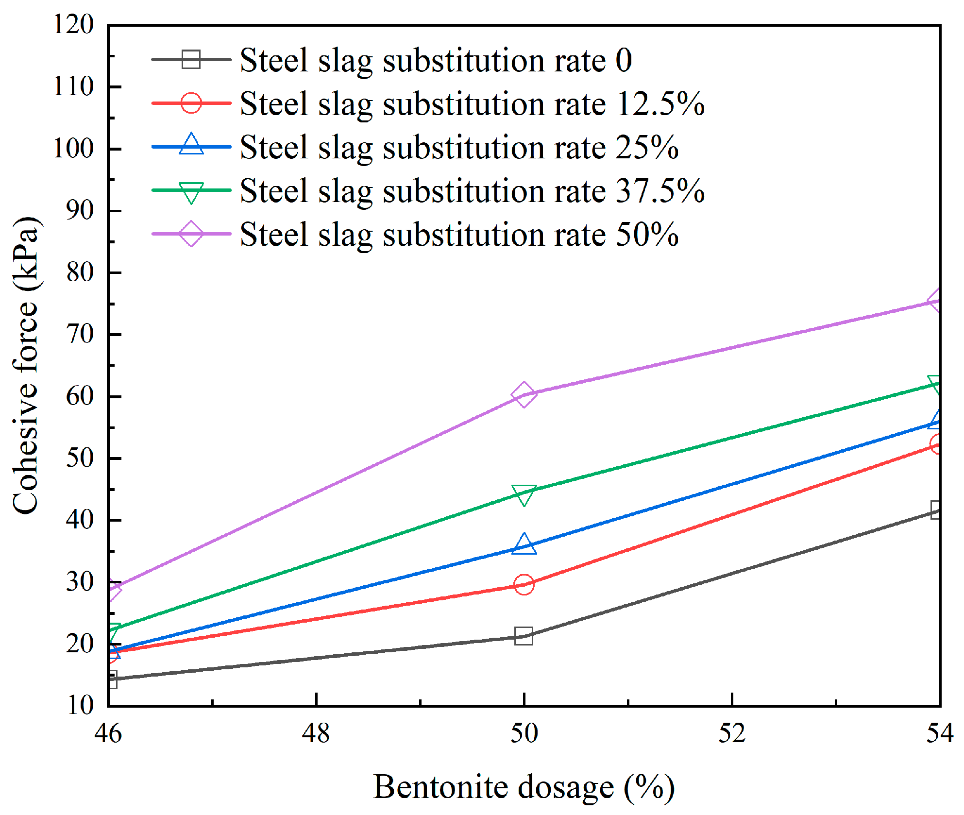
3.2.2. Effect of Bentonite Dosage on the Cohesion of Barrier Materials

In Figure 6, it is clear that the cohesion increases with the increase in bentonite dosage for the same steel slag substitution rate. The range of cohesion is between 14.6 kPa and 28.91 kPa for 46% bentonite dosage, between 21.61 kPa and 60.81 kPa for 50% bentonite dosage, and between 41.92 kPa and 75.65 kPa for 54% bentonite dosage. The increase in cohesion is more obvious, indicating that the bentonite dosage has a greater effect on the cohesion of steel slag–cement–bentonite materials.

3.3. Study on Permeability of Steel Slag–Cement–Bentonite Barrier Material

3.3.1. Effect of Steel Slag Substitution Rate on the Permeability of Barrier Materials

Figure 7 indicates that the permeability coefficient of the barrier material changes with the steel slag substitution rate, respectively. It can be seen from the Figure that with the same bentonite dosage and age, the permeability coefficient of the material with the increase in the steel slag substitution rate shows a decreasing trend. Taking the bentonite dosage at 46% and age 7d as an example, the permeability coefficients of steel slag substitution rates of 0, 12.5%, 25%, 37.5%, and 50% corresponding to age 7d were 8.21 × 10⁻⁵ cm·s−1, 5.96 × 10⁻⁵ cm·s−1, 3.99 × 10⁻⁵ cm·s−1, 1.61 × 10⁻⁵ cm·s−1, and 2.30 × 10⁻⁶ cm·s−1, respectively. The permeability coefficient decreased from 8.21 × 10⁻⁵ cm·s−1 to 5.96 × 10⁻⁵ cm·s−1 when the steel slag substitution rate was increased from 0 to 12.5%. When the steel slag substitution rate was increased from 37.5% to 50%, the permeability coefficient decreased from 1.61 × 10⁻⁵ cm·s−1 to 2.30 × 10⁻⁶ cm·s−1. For the same age and bentonite dosage at 14d and 28d, the permeability coefficient of the material varied with the steel slag substitution rate with a similar magnitude as this pattern. For the same age and bentonite dosage of the material, with the increase in the steel slag substitution rate in the material, the permeability coefficient decreases more and more, indicating that the high dosage of steel slag reduces the permeability coefficient of the material significantly.

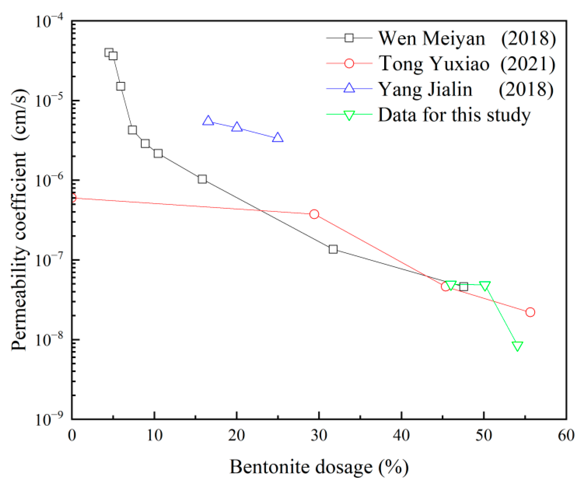
3.3.2. Effect of Bentonite Dosage on the Permeability of Barrier Materials

Figure 8 illustrates the permeability coefficients of cement bentonite structures maintained for 28d with different cement substitutions [24,25,26]. In this study, the bentonite dosage was 46%, 50%, and 54%. From the figure, it can be found that no matter the cement replacer, the permeability coefficient of the cement bentonite-based barrier material decreases with the increase in bentonite dosage, indicating that the addition of bentonite has the ability to reduce the permeability of the barrier wall.

4. Discussion

4.1. Effect of Steel Slag Substitution Rate on the Reaction Mechanism and Microstructure of Barrier Materials

As can be seen in Figure 3, with the increase in steel slag substitution rate (0~50%), the unconfined compressive strength showed a linear decrease, which was closely related to the change in material microstructure by the steel slag substitution rate.
Figure 9 shows the SEM images of soil samples of the same age (28d), same bentonite admixture (54%), and different steel slag substitution rates (0, 12.5%, 25%, 37.5%, and 50%) magnified by a factor of 5000 after the infiltration tests were completed. When there is no steel slag incorporation, a small amount of flocculated structure can be observed, and the material is more porous and well connected internally. With the increase in the steel slag substitution rate, needle-like tricalcium aluminate crystals began to appear, and hydrated calcium silicate gel gradually decreased. Tricalcium aluminate crystals fill the pores, forming a dense skeletal structure. Because the hydration products of steel slag–cement–bentonite material mainly from cement and steel slag is a gelling material, the hydration of cement can provide an alkaline environment for the hydration of steel slag, and with the increase in steel slag, the hydration of cement is weakened, resulting in the generation of less and less Ca(OH)2, which is not conducive to stimulating the activity of steel slag. Steel slag and cement both contain tricalcium aluminate; the hydration product of tricalcium aluminate is calcium aluminate. The content of calcium aluminate will gradually increase with the reaction process. Due to the expansion of calcium aluminate, the gradual increase in the content of calcium aluminate will reduce the pore space of the soil samples, thus reducing the permeability of the soil samples; at the same time, excessive calcium aluminate will reduce the strength properties of the soil samples. This microstructural evolution directly explains the changes in the macroscopic mechanical properties: the swelling of tricalcium aluminate to fill the pores reduces the permeability (e.g., permeability coefficient decreases with the increase in steel slag substitution rate in Figure 7), but an excess of tricalcium aluminate inhibits the generation of the C-S-H gel, leading to weaker cementation and, thus, a reduction in the compressive strength (e.g., the strength decreases with the increase in steel slag substitution rate in Figure 3 decreases).
The mechanism of microstructure influence on macroscopic properties is clarified by referencing SEM images (Figure 9) with mechanical and permeability data (Figure 3 and Figure 7). For example, at 50% steel slag substitution (Figure 9e), a dense tricalcium aluminate skeleton fills the pores, consistent with a low permeability coefficient of 2.30 × 10⁻⁶ cm/s (Figure 7c); however, a reduction in the gelling products results in a compressive strength of only 58.18 kPa (Figure 3a).

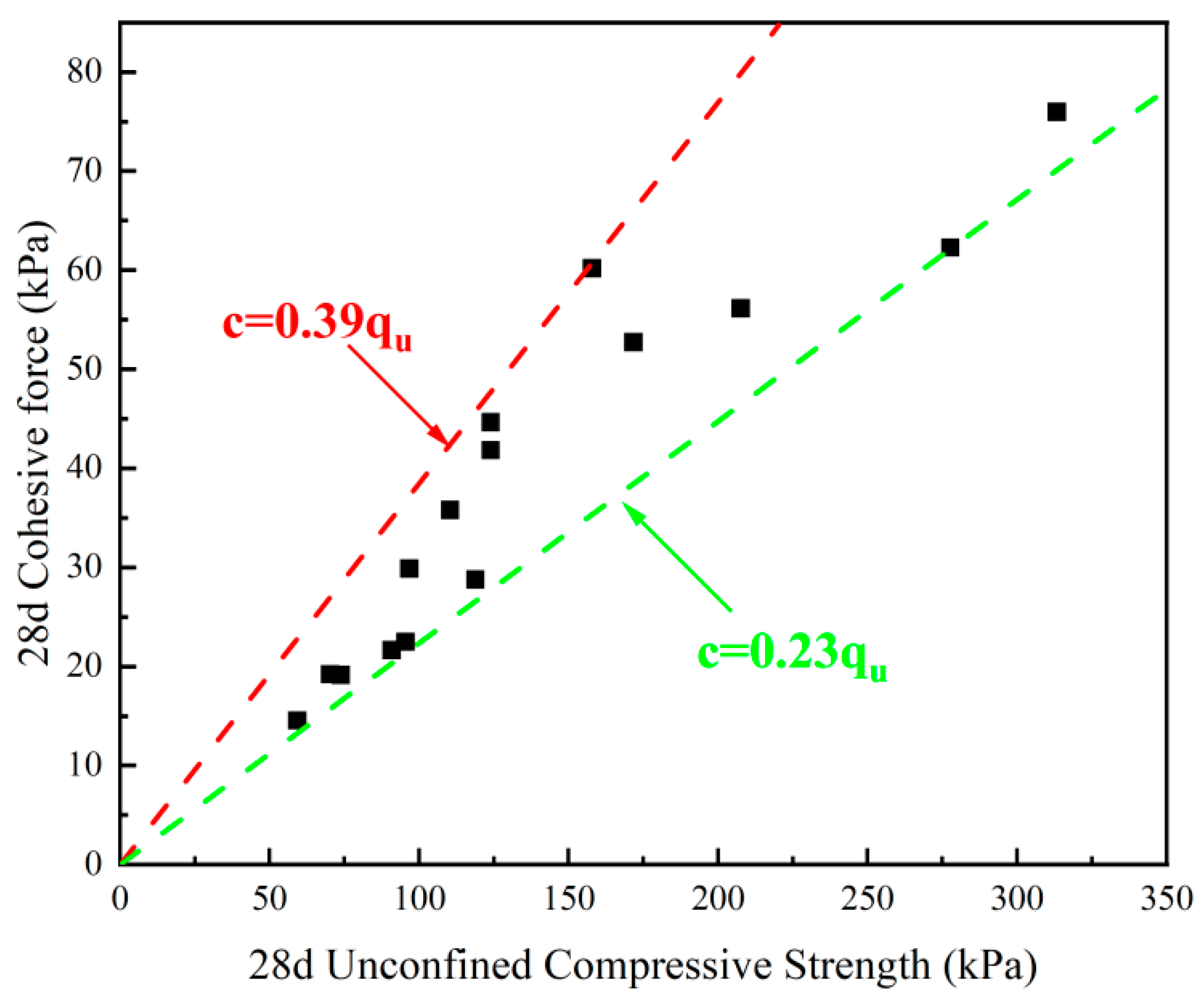
4.2. Analysis of the Correlation Between Cohesion and Unconfined Compressive Strength of Barrier Materials

In the process of barrier wall design for special sites on slopes, it is difficult to ensure stability by simply relying on the unconfined compressive strength alone, and the shear strength index can only be obtained through indoor tests, which is a process that consumes energy and material resources. This subsection links the unconfined compressive strength and cohesive strength and studies the relationship between the two changes through the unconfined compressive strength of the material to predict the cohesive strength of the material, which can be convenient and effective for ensuring that the design value meets the engineering needs. As can be seen in Figure 10, it is not difficult to find that the higher the unconfined strength of the material, the larger the corresponding cohesive force. The cohesive force and the unconfined compressive strength basically satisfy c = (0.23~0.39)qu, which provides a reference for the construction design of the barrier wall. The coupling relationship between unconfined compressive strength and cohesion pointed out in this subsection is a research focus that can be used as a practical engineering application, and in the future, this point can be continued to propose other directions that have not been explored in other studies such as ‘the effect of age on the scaling factor’.

5. Conclusions

Taking the steel slag–cement–bentonite barrier wall as the research object. The novel idea of using steel slag to replace part of the cement component as a bentonite barrier wall was adopted, and the variable head penetration test and scanning electron microscope test as the research means the effects of steel slag substitution rate and bentonite dosage on the strength characteristics and permeability properties of the barrier material were investigated. The following conclusions were drawn:
(1)
The unconfined compressive strength of steel slag–cement–bentonite barrier material decreases gradually with the increase in steel slag substitution rate and has a linear relationship with the steel slag substitution rate; with the increase in bentonite dosage, the strength has an exponential relationship with the bentonite dosage.
(2)
Steel slag–cement–bentonite barrier material cohesion with the increase in steel slag substitution rate gradually decreased, and with the steel slag substitution rate is a negative exponential relationship; cohesion with the increase in bentonite dosage and increase, and with the bentonite dosage is a linear relationship.
(3)
A higher unconfined compressive strength of the steel slag–cement–bentonite barrier material corresponds to greater cohesion. By establishing the relationship between cohesion and change in unconfined compressive strength, it is found that cohesion and unconfined compressive strength basically satisfy c = (0.23~0.39)qu.
(4)
The mechanical properties of steel slag–cement–bentonite barrier materials can be determined by establishing a correlation between cohesion and unconfined compressive strength. When meeting the engineering specifications, the unconfined compressive strength serves as a predictive parameter for estimating shear strength characteristics, enabling systematic evaluation of both strength parameters.
(5)
The permeability of steel slag–cement–bentonite barrier materials exhibits an inverse correlation with steel slag substitution rate (0~50%) and bentonite dosage (46~54%). Both parameters collectively dominate the decreasing trend of permeability as their values increase.

Author Contributions

Conceptualization, H.L. and L.G.; methodology, L.G.; software, A.Z.; validation, H.L. and W.Z.; formal analysis, H.L.; investigation, L.G.; resources, H.X.; data curation, L.G.; writing—original draft preparation, H.L.; writing—review and editing, W.Z.; visualization, L.G.; supervision, H.X.; project administration, H.X. and A.Z.; funding acquisition, H.L. All authors have read and agreed to the published version of the manuscript.

Funding

This research received no external funding.

Institutional Review Board Statement

Not applicable.

Informed Consent Statement

Not applicable.

Data Availability Statement

The original contributions presented in the study are included in the article, further inquiries can be directed to the corresponding authors.

Conflicts of Interest

The remaining authors declare that the research was conducted in the absence of any commercial or financial relationships that could be construed as potential conflicts of interest.

References

  1. Xue, Q.; Zhan, L.; Hu, L.; Zhan, L.; Li, J. Environmental geotechnics: State-of-the-art of theory, testing and application to practice. China Civ. Eng. J. 2020, 53, 80–94. [Google Scholar]
  2. Xie, J.; Li, F.S. Overview of the Current Situation on Brownfield Remediation and Redevelopment in China; World Bank: Washington, DC, USA, 2010. [Google Scholar]
  3. Ma, X. Construction and Improvement of Water Pollution Prevention and Control Mechanism—A Review of the Action Plan for the Prevention and Control of Water Pollution. People’s Yellow River 2021, 43, 165. [Google Scholar]
  4. Jefferis, S. Cement-bentonite slurry systems. In Proceedings of the International Conference on Grouting and Deep Mixing, New Orleans, LA, USA, 15–18 February 2012; ASCE: Reston, VA, USA, 2012; pp. 1–24. [Google Scholar]
  5. Opdyke, S.M.; Evans, J.C. Slag-cement bentonite slurry walls. J. Geotech. Geoenvironmental Eng. 2005, 131, 673–681. [Google Scholar] [CrossRef]
  6. Peng, X.; Liu, C.; Li, S.; Jiang, Y.; Zeng, L. Research on the Setting and Hardening Performance of Alkali-activated Steel Slag-slag Based Cementitious Materials. J. Hunan Univ. (Nat. Sci.) 2015, 42, 47–52. [Google Scholar]
  7. Zhang, K. Study on Application of Fluidized Waste Soil Backfilling Foundation Pit Side Wall. Master’s Thesis, Jiangsu University of Science and Technology, Zhenjiang, China, 2021. [Google Scholar]
  8. Wu, Y.; Ben, P.; Wu, L.; Lv, W.; Zhang, G. Overview of domestic and international steel slag treatment and resource utilization technology development status quo. Environ. Eng. 2021, 39, 161–165. [Google Scholar]
  9. Li, Y. Experimental Analysis of the Influence of Basalt Fiber on Mechanical Properties of Steel Slag Concrete at Low Temperature. Master’s Thesis, Anhui University of Science and Technology, Huainan, China, 2017. [Google Scholar]
  10. Han, Y. Preparation and performance study of steel slag-based no-burn filter balls. Master’s Thesis, Nanjing Normal University, Nanjing, China, 2021. [Google Scholar]
  11. Guo, J.L.; Bao, Y.P.; Wang, M. Steel slag in China. Treatment, recycling, and management. Waste Manag. 2018, 78, 318–330. [Google Scholar] [CrossRef] [PubMed]
  12. Altun, I.A.; Ylmaz, I. Study on steel furnace slags with high MgO as additive in Portland cement. Cem. Concr. Res. 2002, 32, 1247–1249. [Google Scholar] [CrossRef]
  13. Kourounis, S.; SiVilis, S. Properties and hydration of blended cements with steelmaking slag. Cem. Concr. Res. 2007, 37, 815–822. [Google Scholar] [CrossRef]
  14. Ding, G.; Jiang, L.; Zhang, J. Influence of Bentonite on Hydrating and Hardening of Cement. J. Wuhan Univ. Technol. 2012, 34, 20–23. [Google Scholar]
  15. Chen, L.; Hu, F.; Hu, G. Experiment on performance improvement of cement-soil with the dual admixture of fly ash and bentonite in Wuhan area. Explor. Eng. (Rock Soil Drill. Tunneling) 2019, 46, 62–67. [Google Scholar]
  16. Wang, Z.J.; Zhao, B.M.; Royal, A.C. Investigation of erosion of cement-bentonite via piping. Adv. Mater. Sci. Eng. 2017, 32, 1–8. [Google Scholar] [CrossRef]
  17. ASTM D 4287; Standard Practice for Classification of Soils for Engineering Purposes (Unified Soil Classification System). ASTM International: West Conshohocken, PA, USA, 2011.
  18. Mason, B. The Constitution of some basic Open-hearth slags. J. Iron Steel Inst. 1944, 1, 69–80. [Google Scholar]
  19. Shi, H.; Huang, K.; Wu, K.; Guo, X. Research Advance on Activation and Mechanism of Steel Slag Activity. Fly Ash Compr. Util. 2011, 48–53. [Google Scholar] [CrossRef]
  20. Zhang, T. Mixture Ratio Test and Model Test Study of Cement-bentonite Mud Cutoff Wall. Master’s Thesis, Hebei University, Baoding, China, 2019. [Google Scholar]
  21. Huang, L. Laboratory Researches on Mixing Proportion of Cement-Bentonite Slurry Cutoff Wall. Master’s Thesis, Tongji University, Shanghai, China, 2008. [Google Scholar]
  22. ASTM C617/C617M-15; Standard Practice for Capping Cylindrical Concrete Specimens. ASTM International: West Conshohocken, PE, USA, 2015. [CrossRef]
  23. GB/T 50123-2019; Geotechnical Test Method Standards. Ministry of Housing and Urban-Rural Development of the People’s Republic of China: Beijing, China; China Planning Press: Beijing, China, 2019.
  24. Tong, Y. Experimental Study on the Characteristics of Cement-soil Improved by Bentonite. Master’s Thesis, Hefei University of Technology, Anhui, China, 2021. [Google Scholar]
  25. Wen, M. Study on Controlling Cadmium Pollution of Groundwater by Fly Ash Bentonite Blocking Wall. Master’s Thesis, Chengdu University of Technology, Chengdu, China, 2018. [Google Scholar]
  26. Yang, J. Experimental study on age effect of slag-cement-bentonite engineering properties. Master’s Thesis, Zhejiang University, Hangzhou, China, 2018. [Google Scholar]
Figure 1. Particle size distribution.
Applsci 15 04544 g001
Figure 2. Direct shear apparatus and its schematic diagram.
Applsci 15 04544 g002
Figure 3. Change in unconfined compressive strength of steel slag–cement–bentonite material with substitution rate of steel slag under different bentonite dosages.
Applsci 15 04544 g003
Figure 4. Change of unconfined compressive strength of steel slag–cement–bentonite materials with the bentonite dosage at different ages.
Applsci 15 04544 g004
Figure 5. Change of cohesion of steel slag–cement–bentonite material with replacement rate of steel slag under different bentonite dosages.
Applsci 15 04544 g005
Figure 6. Change of cohesive force of steel slag–cement–bentonite material with bentonite dosage under different steel slag replacement rates.
Applsci 15 04544 g006
Figure 7. Change in permeability coefficient of steel slag–cement–bentonite material with replacement rate of steel slag under different bentonite dosages.
Applsci 15 04544 g007
Figure 8. Comparison of 28d permeability coefficient of different materials with bentonite dosage in the literature [24,25,26].
Applsci 15 04544 g008
Figure 9. SEM image of steel slag–cement–bentonite material with 54% bentonite dosage 28 days after completion of penetration test.
Applsci 15 04544 g009
Figure 10. Relationship between cohesion and unconfined compressive strength of steel slag–cement–bentonite materials after 28d curing.
Applsci 15 04544 g010
Table 1. Main chemical composition and percentage of bentonite.
Chemical ComponentsSiO2Al2O3Fe2O3CaONa2OMgOSO3K2OOther Components
Mass percentage (%)59.7616.135.554.924.733.991.931.451.54
Table 2. Basic physical indexes of bentonite.
Physical IndicatorMeasurement Results
Loss on filtration (mL)≤18
Liquid limit (%)169
Plastic limit (%)20
Plasticity index149
Expansion index (mL/2g)24
Table 3. Main chemical composition and percentage of cement.
Chemical ComponentsCaOSiO2Al2O3Fe2O3SO3MgOK2OOther Components
Mass percentage (%)55.0323.076.665.313.843.331.011.75
Table 4. Main performance indexes of cement.
Testing Items Stability3-Day Flexural
Strength (MPa)
3-Day Compressive Strength (MPa)Initial Condensation
Time (min)
Final Condensation
Time (min)
28-Day Flexural
Strength (MPa)
28-Day Compressive Strength (MPa)
National standard≥300Eligible≥3.5≥17≥45≤600≥6.5≥42.5
Measured value363Eligible5.525.41612348.449.8
Table 5. Chemical composition of steel slag.
IngredientCaOFe2O3SiO2Al2O3MgOMnOCr2O3Na2OP2O5TiO2SO3
Content (%)34.3026.2219.647.724.142.492.081.060.760.520.49
Table 6. Relationship between basicity and mineral composition of steel slag.
Olivine slag (geology)0.9~1.4
Magnesium Rosette1.4~1.6
Dicalcium silicate slag1.6~2.4
Tricalcium silicate slag>2.4
Table 7. Test mix scheme.
NumberWater (g)Cement (g)Steel Slag (g)Bentonite (g)Steel Slag Substitution Rate (%)Bentonite Dosage (%)Rw/b
A17501200102.20466.25
A275010515102.212.5466.25
A37509030102.225466.25
A47507545102.237.5466.25
A57506060102.250466.25
B17501200120.00506.25
B275010515120.012.5506.25
B37509030120.025506.25
B47507545120.037.5506.25
B57506060120.050506.25
C17501200140.90546.25
C275010515140.912.5546.25
C37509030140.925546.25
C47507545140.937.5546.25
C57506060140.950546.25
Disclaimer/Publisher’s Note: The statements, opinions and data contained in all publications are solely those of the individual author(s) and contributor(s) and not of MDPI and/or the editor(s). MDPI and/or the editor(s) disclaim responsibility for any injury to people or property resulting from any ideas, methods, instructions or products referred to in the content.

