Abstract
In order to alleviate the risk of landslides on high and steep slopes during excavation, slope protection coal pillars are commonly increased at the site to maintain slope stability, which causes a considerable waste of coal. In roof cutting for pressure relief at quarries, the movement of the overburden structure is artificially regulated by blasting. However, there is a lack of theoretical research on the impact on the slope movement. In order to explore how blasting roof cutting affects the deformation and fracture of slopes, a case study of the 10101 working face of Xinyuan Coal Mine was carried out. The particle flow code numerical simulation of the mining with different heights of roof cutting was performed to analyze the impact of the height of roof cutting on the movement of overlaying rock formation, the development of slope fractures, stress distribution, collapse angle, slope deformation and fracture, etc. The research results are as follows: the overlaying rock formation can be divided into the stable zone, the rotary zone and the subsidence area by displacement; a reasonable roof-cutting height allows the cutting and crushing of the overlaying rock formation, as a result of which the movement boundary is offset to cutting line and the slope is within the stable area; at the same time, the horizontal displacement of the rock formation in the rotary zone, the collapse angle and the stress at slope bottom are reduced, which controls the deformation and failure of slope by inhibiting the development of cracks at slope bottom and reducing the rotation of the rotary zone to the goaf zone. The research results provide certain references for controlling ground sedimentation and slopes in blasting roof cutting.
1. Introduction
In the continuous development of mining projects, the deformation and failure of overlying slopes caused by mining are increasingly prominent, which seriously threatens safe production, the surrounding ecological environment and the safety of residents and property [1]. The in-depth exploration of the deformation and failure of overlying slopes in roof cutting and the control strategies is of great significance to ensuring sustainable mining.
A variety of factors seriously challenge the stability of overlying slopes during mining [2]. Among them, the depth and intensity of mining are the important influencing factors. As the ground stress increases with the mining depth, the pressure on the rock mass also rises to cause damage to the integrity of the rock mass, and, thereby, the slope stability is affected; the increased mining intensity means expansion and intensification of the disturbance to the rock mass, which further weakens the stability of the overlying slope and increases the risk of deformation and failure [3].
Geological structures have a profound impact on slope deformation and destruction. Geological structures such as faults and joints can damage the continuity of rock mass to cause the formation of potential sliding surfaces [4]. During mining, these parts are more prone to stress concentration, which causes displacement and deformation of slope along the tectonic plane and even geological disasters such as landslides [5]. The mechanical properties of rocks cannot be ignored either, as the differences in mechanical parameters such as strength and elastic modulus determine their different deformation responses to mining stress [6]. Slopes composed of soft rocks are more prone to plastic deformation, while hard rock slopes may be unstable due to brittle failure [7]. Groundwater plays a complex role in slope stability. On the one hand, the penetration of groundwater reduces the shear strength and increases the weight of rock mass. On the other hand, changes in pore water pressure change the stress of rock mass. When the pore water pressure increases, the effective stress decreases, resulting in decreased slope stability.
In addition, unreasonable mining sequences and methods also exacerbate slope deformation and failure [8,9,10]. Improper mining sequence can lead to uneven stress distribution, causing local stress concentration to accelerate slope instability; excessive blasting and other inappropriate mining methods will cause additional damage to rock mass and destroy the original stable structure of the slope [11].
To address the deformation and failure of overlying slopes caused by mining, many control measures have been developed [12]. Support technology is a common method. The provision of bolts, cables and other support structures to introduce prestress on slope rock mass can enhance the integrity and stability of rock mass and resist the influence of mining stress [13,14,15]. It is equally critical to optimize the mining scheme. Reasonable mining sequence, mining intensity and mining method can effectively reduce the disturbance to slopes during mining and lower the degree of stress concentration, thereby maintaining the stability of slopes [16,17,18,19,20,21,22,23,24]. Furthermore, a monitoring and early warning system is indispensable. Real-time monitoring of the displacement, stress, groundwater level and other parameters of slopes allows timely discovery of potential deformation and failure, which provides a basis for the adoption of corresponding control measures to avoid disasters [25,26,27,28].
At the mining site, a combination of ground and underground measures is used to maintain slope stability. Ground measures include slope cutting and anti-slip piles, etc. Most ground measures are costly and require long construction periods; the underground measures are mostly the increase in slope protection coal pillars, which also causes a lot of waste of coal. Roof cutting for pressure relief is an important innovation in safe and efficient coal mining. It mainly allows artificial regulation of the movement of overburden structures to control the overlaying rock formation and surrounding rocks [29,30,31,32,33,34,35,36]. However, there is a lack of theoretical research on the impact of roof cutting on slope movement and ground subsidence. In order to explore how roof cutting affects slope stability, a case study of the 10101 working face of Xinyuan Coal Mine was carried out. The slope deformation and failure during mining were studied, which provides certain references for controlling ground subsidence and the slope.
2. Engineering Background
The industrial site of Shanxi Dongtai Xinyuan Coal Industry Co., Ltd. (located in Linfen City, China) was formed by large-scale excavation and filling. The company set up a platform of about 18 m~50 m wide at the top by excavating the entire 10 m creep slope, which formed the current southern slope topography.
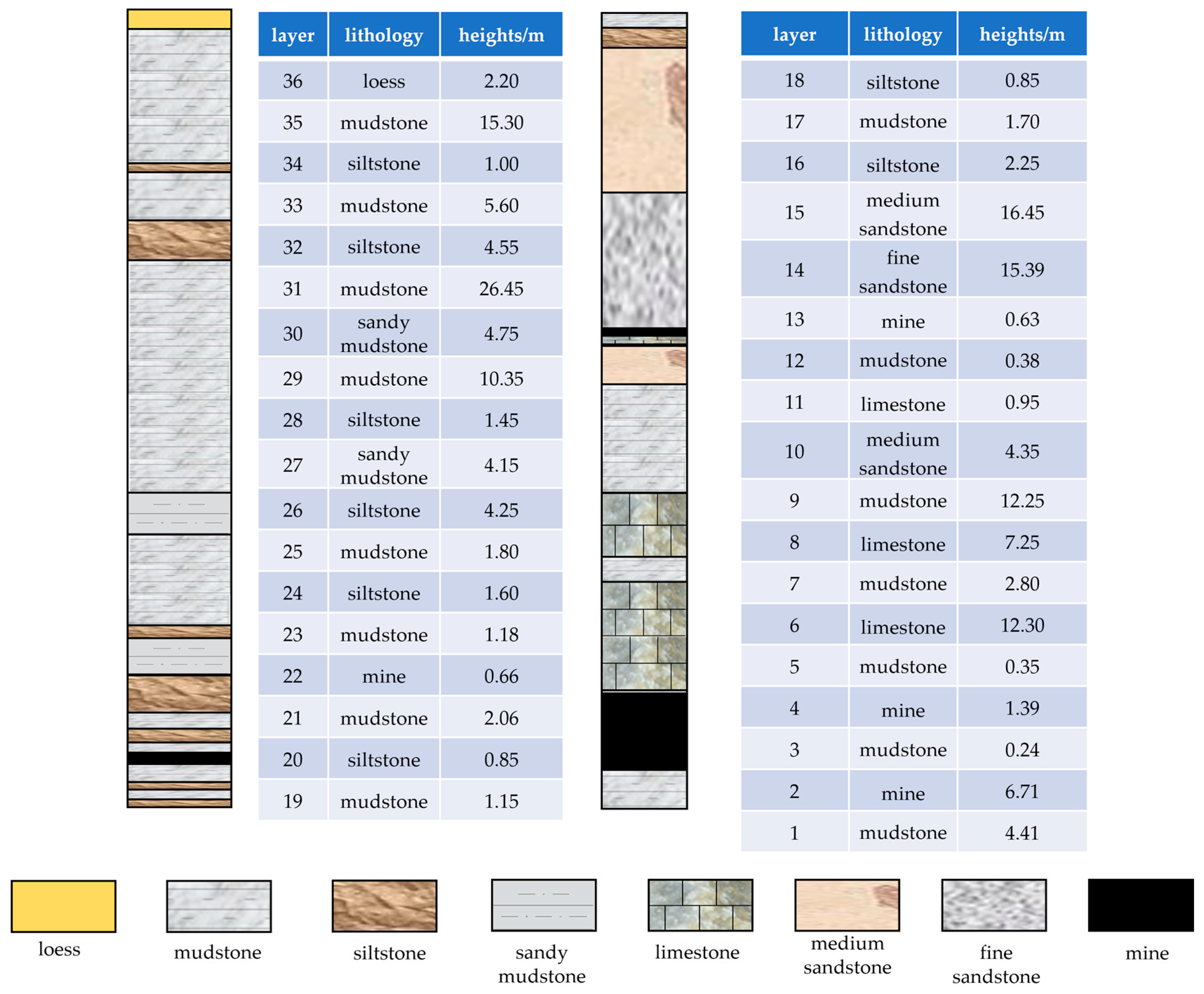
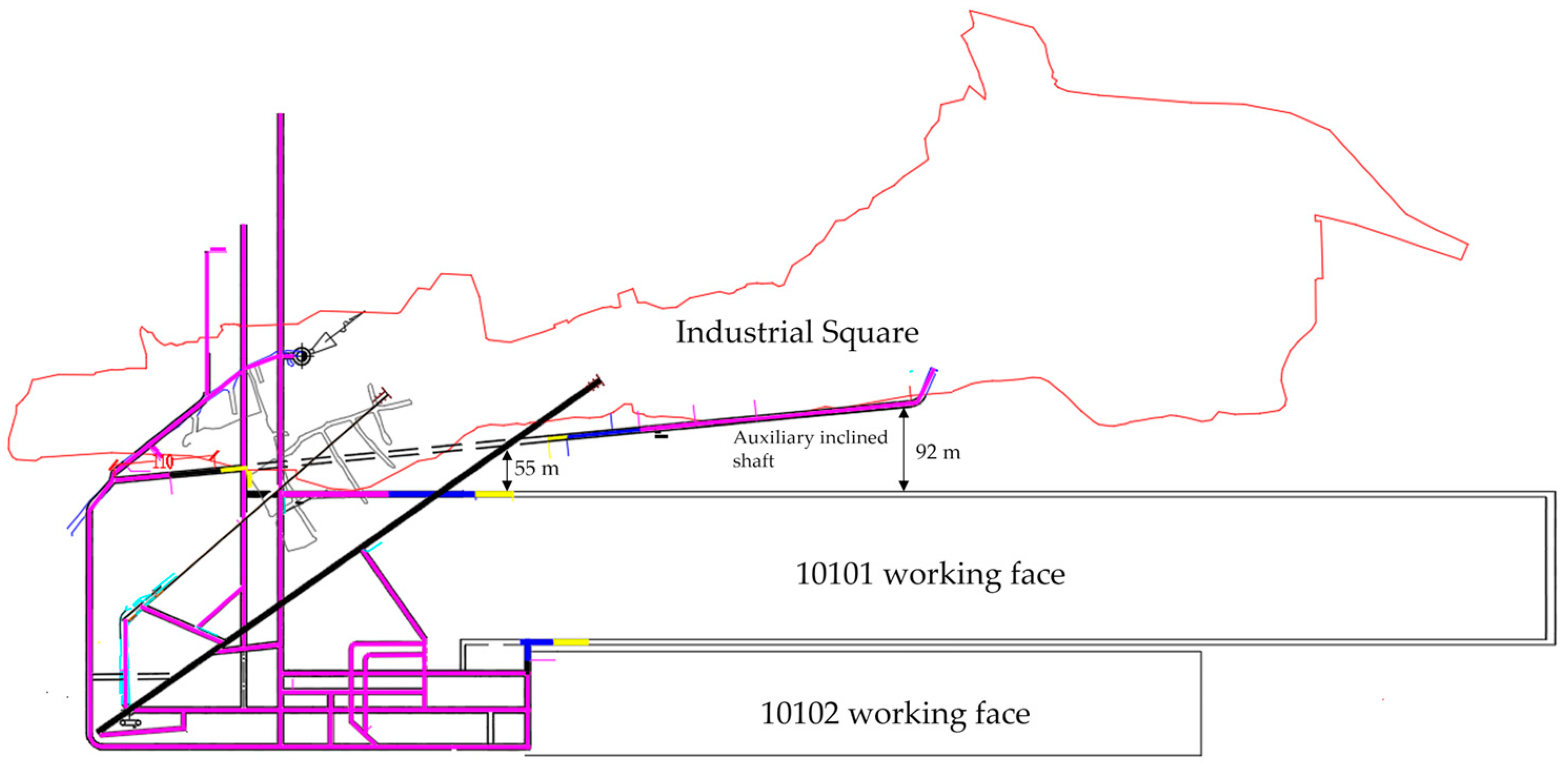
The burial depth of the 10101 working face was about 160 m; the thickness of the coal seam was 8.34 m, including 0.24 m mudstone gangue; and the overlaying limestone formation of the coal seam was 12.30 m. The length of the 10101 working face was 155 m, and the back stopping was carried out through receding full-collapse integrated mechanization with a large mining height of 8 m at one time. The mining was proceeded along the bottom plate and supported by bolts, nets, steel ladder beams and anchor cables. This blasting roof-cutting test was located in the 10101 transportation channel. Figure 1 is a histogram of a borehole near the transportation channel. The south side of the working surface was the 10102 working surface, and the north side of the work surface was the industrial square. The specific location of the work surface is shown in Figure 2.
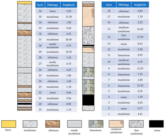
Figure 1.
Composite stratigraphic column.
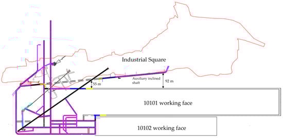
Figure 2.
The 10101 working face location map.
The slope deformation caused by the mining at the 10101 working face was mainly manifested as surface deformation and damage to buildings on the slope.
According to the measurement results at the owner’s monitoring points above 10101 working face, the cumulative maximum surface subsidence after mining was up to 4.4 m, and dense crack zones were developed. Due to the mining, the brick-and-concrete houses in the original slope-top village above the transportation channel of the working surface suffered a local collapse and a large number of vertical cracks and were no longer suitable for living.
Given the serious slope deformation, urgent slope control measures were needed. At the site, a combination of ground and underground measures was mostly used to maintain the slope stability. Ground measures included slope cutting, anti-slip piles, etc. Most ground measures were costly and required long construction periods; the underground measures were mostly the increase in slope protection coal pillars, which also caused a lot of waste of coal.
At the same time, roof cutting for pressure relief is used, where the movement of the overburden structure is artificially regulated to control the overlaying rock formation and surrounding rocks. However, there is a lack of theoretical research on its impact on slope movement and ground subsidence. Therefore, in the case study of the 10101 working face, particle flow code numerical simulation was carried out to study the influence of different roof-cutting heights on slope deformation and damage.
3. Simulation Schemes
3.1. Model Building
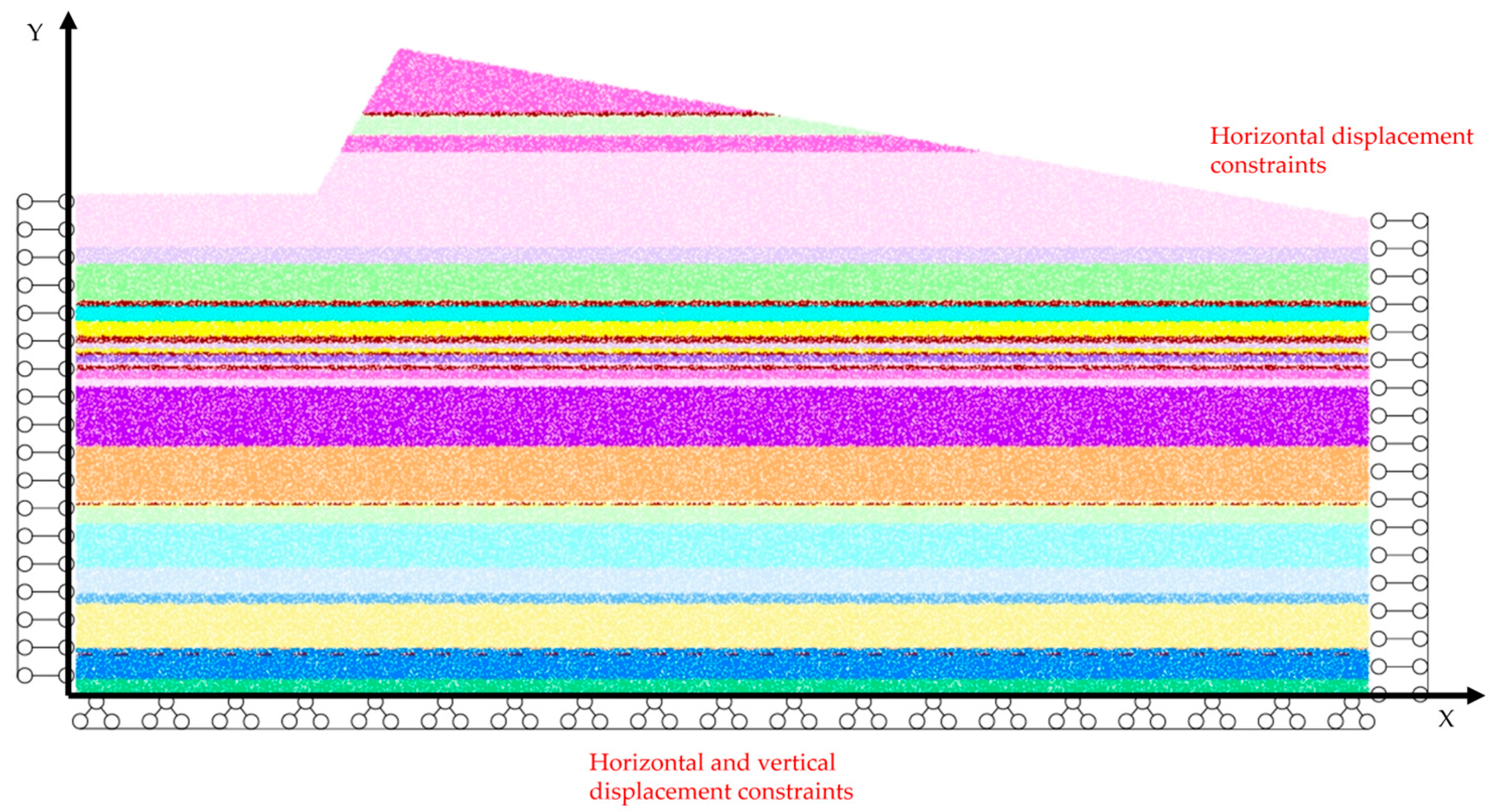
Based on the requirements of on-site testing of transportation channel, a coordinate system (with the lower left corner as the origin, the inclination direction as the X-axis and the vertical direction as the Y-axis) of a two-dimensional numerical model was established with a histogram of the borehole (Figure 1) near the area as the modeling basis. In order to eliminate the boundary effect of the numerical model, a 360 × 180 m2 particle flow model with a total of 191,166 particles was established. The overlaying rock formation was of a layered structure, where the slope angle was 60°. The horizontal and lateral displacement of the left and right boundaries were constrained, with solid support provided at the bottom. The upper boundary was a free boundary, and a gravity load of 9.8 m/s2 was applied. Mining was simulated by deleting the particles corresponding to the coal seam (The open-off cut was 100 m away from the left boundary of the model, and the coal mining was simulated through excavation for 180 m along the inclination.). After each excavation, the balance was achieved if the average ratio of unbalanced forces in the numerical model was less than or equal to 1 × 10⁻⁵. The numerical model of particle flow is shown in Figure 3.
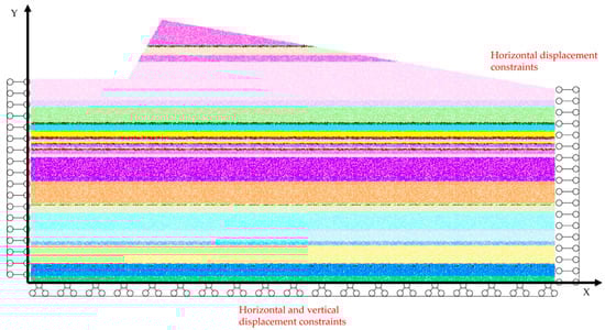
Figure 3.
Numerical model of particle flow.
In the model, parallel bonding of bulk particles was adopted, and the microscopic parameters were calibrated in accordance with the macroscopic mechanical parameters of coal and rock (Table 1). Through a series of numerical simulation tests of uniaxial compression, Brazilian split and biaxial compression of the bonded particle model, the microscopic parameters were continuously adjusted by trial and error to reduce the error with the required macroscopic mechanical parameters, thereby obtaining reasonable microscopic parameters. The calibrated micro parameters of each rock formation are shown in Table 2.

Table 1.
Macromechanical parameters of each rock stratum in the model.
Table 2.
Mesoscopic parameters of each rock layer in the particle model.
3.2. Roof-Cutting Schemes
During roof cutting of the working surface, as the height of roof cutting increases, when one or more layers of harder rock formations in the overlying top plate are cut off, the cut gangue can limit the movement of the high-level rock formations, thereby inhibiting the sinking of the top plate. The control layer in the overlaying rock formation, that is, the high-level rock formation that forms a rock beam structure, isolates the upper and lower parts of the rock formation, weakening the impact of the collapse of the lower rock formation on the upper rock formation and supporting the overlaying rock formation, especially the slope.
As illustrated in the histogram of the #1 borehole near the transportation channel in Figure 2, the hard rock formation of the working surface’s top plate was mainly limestone, fine sandstone and medium sandstone, and the control layer is made up of medium sandstone.
In order to analyze the influence of the height of roof cutting on the collapse of the overlaying rock formation and the deformation and fracture of the slope, the simulation parameters were determined after theoretical analysis, followed by the formulation of a control design plan for the height of roof cutting. The specific content is as follows: the fixed angle of roof cutting is 0°, and with the height of roof cutting as a variable, 5 sets of controlled experiments were set as shown in Table 3.
Table 3.
Experimental design.
After analysis of the displacement, stress changes and fracture development of overlaying rock formations and slopes at different heights of roof cutting, a reasonable height of roof cutting was obtained, which provides a basis for understanding the law of the influence of roof cutting on the deformation and fracture of slope.
4. Analysis of the Influence of the Height of Roof Cutting on Displacement
4.1. Analysis of the Displacement of the Overlaying Rock Formations in Mining Without Roof Cutting
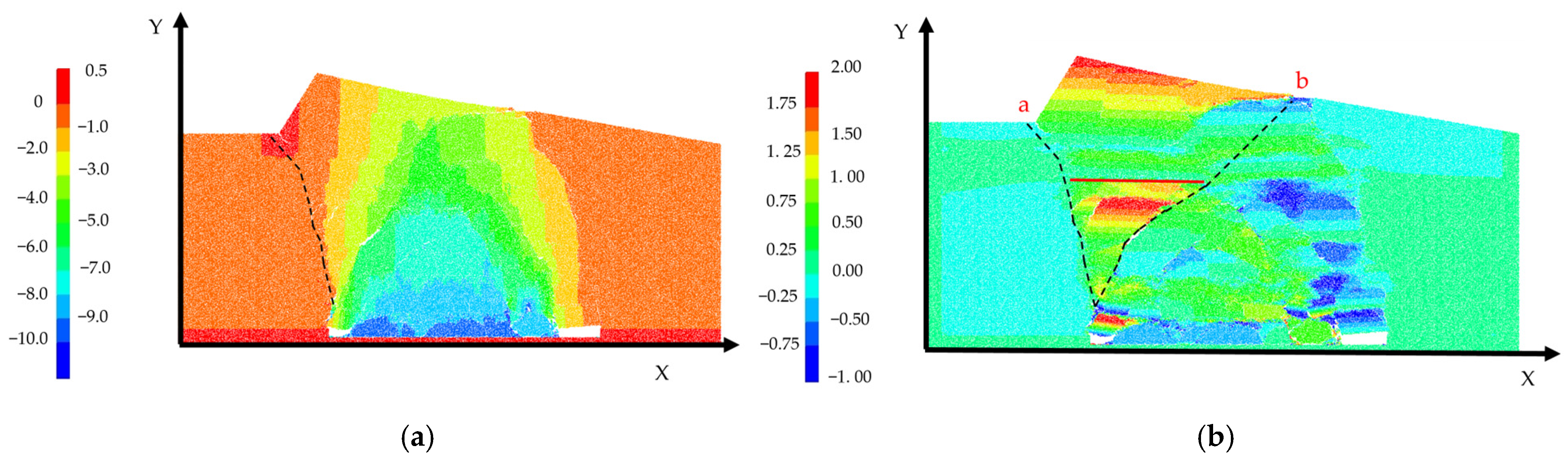
The displacement cloud diagram of the overlaying rock formations in mining is shown in Figure 4. Due to horizontal stress and self-weight, the surrounding rock formations moved horizontally and vertically toward the goaf zone. The vertical displacement was toward the goaf zone, and the horizontal displacement was toward the goaf zone or the free surface. This resulted in the crushing of the internal rock mass of the slope to a certain extent and reduced its mechanical strength and stability, leading to deformation, fracture and instability-induced slippage.
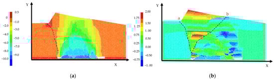
Figure 4.
The displacement cloud diagram of the overlaying rock formations in mining: (a) vertical displacement; (b) horizontal displacement.
As shown in Figure 4a, the area with the largest vertical displacement was located in the arched area above the goaf zone, forming a distinct arched collapse zone; as can be seen from the horizontal displacement cloud diagram in Figure 4b, the rock formation displacement at the upper left arched collapse zone (the area between the ab lines) was downward vertical displacement and rightward horizontal displacement, which was comprehensively manifested as rotation to the goaf zone where there was concentrated triangular horizontal displacement; the rock formation at the upper right collapse zone was manifested as downward vertical displacement and minor horizontal displacement; on the left side of the arched collapse zone (that is, the left side of the a line), there was a minor horizontal and vertical displacement, and the rock formation tends to stabilize.
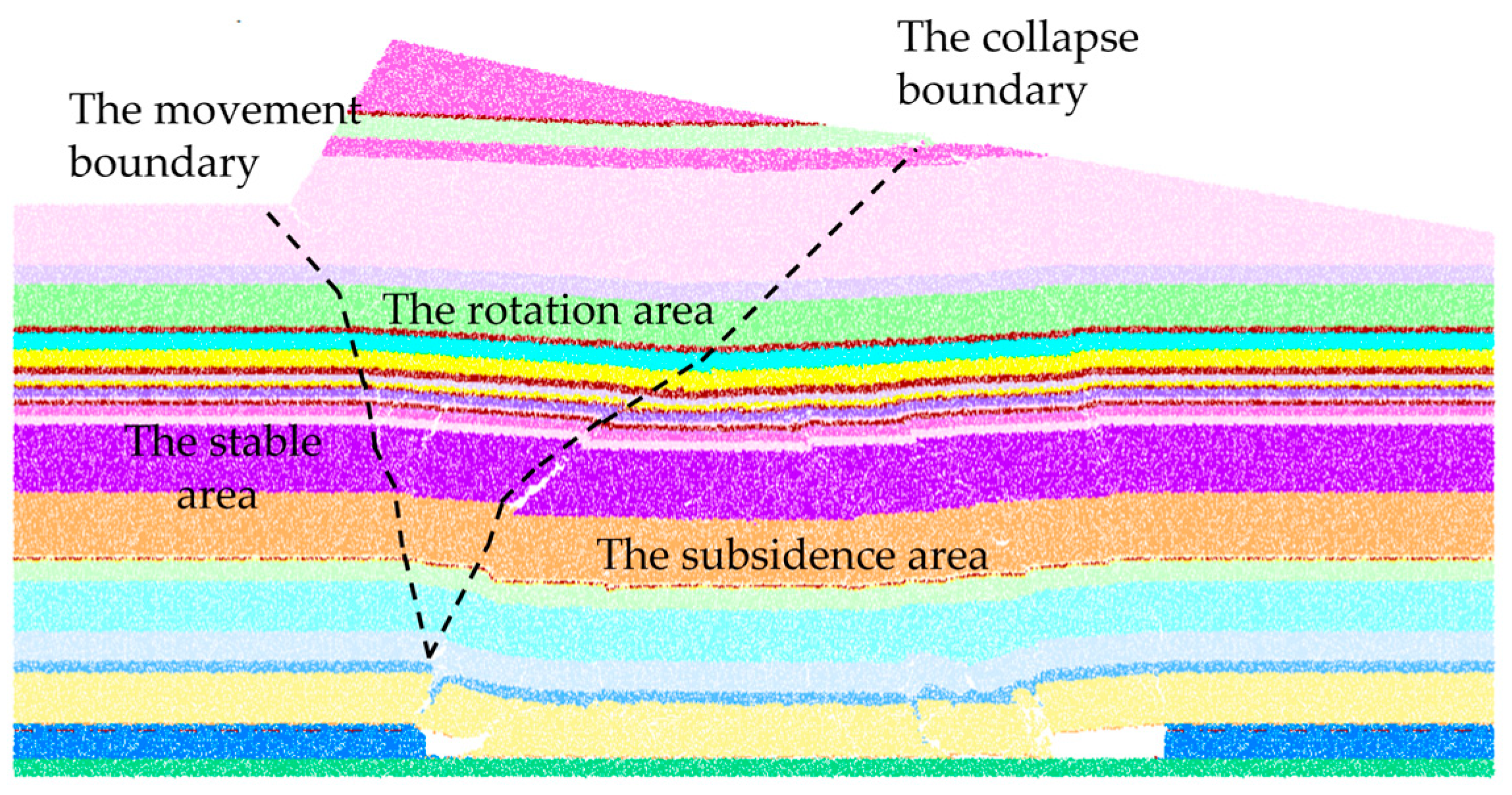
The overlaying rock formation is divided into three areas by the displacement with movement and the collapse boundaries as the dividing lines, as shown in Figure 5. The movement boundary was the dividing line with horizontal displacement close to 0. The collapse boundary is composed of the left half of the arched collapse zone and its extension. The subsidence area was below the collapse boundary, mainly characterized by vertical displacement with minor horizontal displacement towards the goaf zone; the rotation area was within the collapse and the movement boundaries, where there was large vertical and horizontal displacement. The reason for the large deformation was the traction of the collapsed rock formations in the subsidence area, and therefore, the overall displacement was the rotation to the goaf zone; the stable area was located in the rock formation on the left side of the movement boundary, characterized by minor horizontal and vertical displacement. The rock formations in the stable area were overall stable without large deformation.
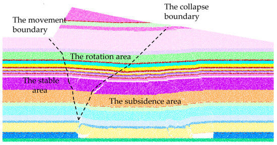
Figure 5.
Schematic diagram of slope zoning.
4.2. Analysis of the Influence of the Height of Roof Cutting on the Displacement of Overlaying Rock Formations
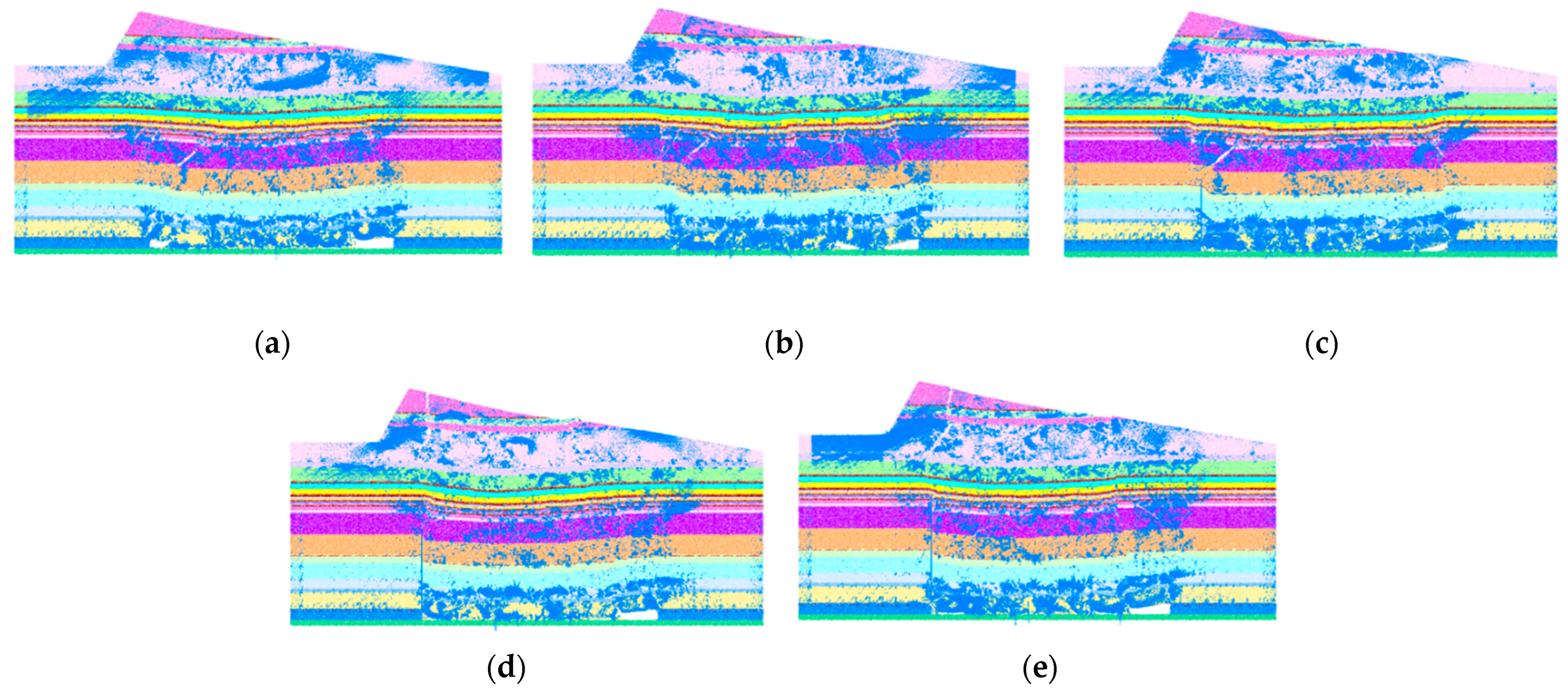
Blasting roof cutting was performed at the 10101 working face. The displacement simulation results of the overlaying rock formation under different heights of roof cutting are shown in Figure 6 and Figure 7.
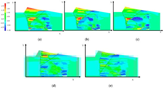
Figure 6.
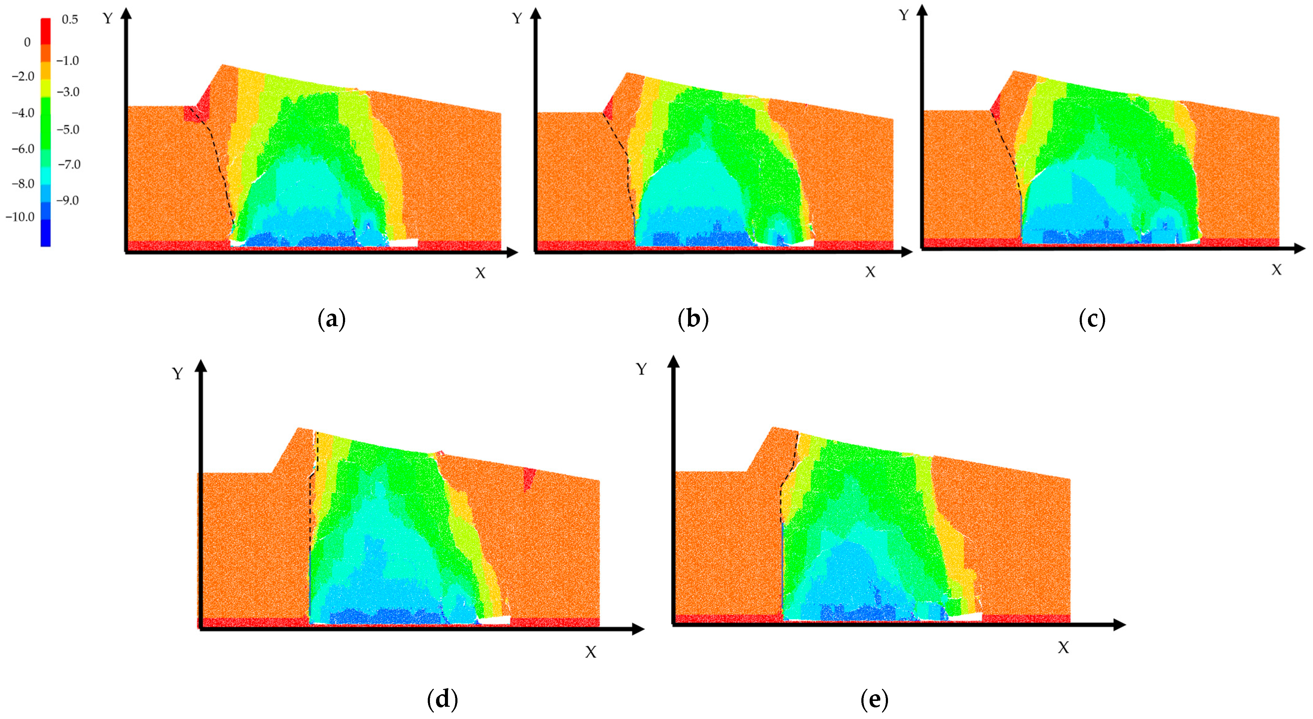
Horizontal displacement of overlying rock layers under different roof-cutting heights: (a) 0 m; (b) 20 m; (c) 40 m; (d) 60 m; (e) 80 m.
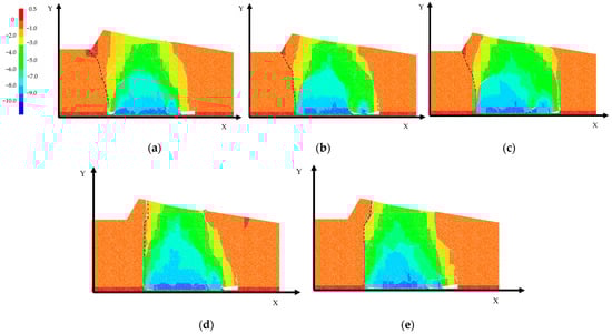
Figure 7.
Vertical displacement of overlying rock formation under different heights of roof cutting: (a) 0 m; (b) 20 m; (c) 40 m; (d) 60 m; (e) 80 m.
When the height of the roof cutting was 20 m, the 12.30 m thick limestone top plate above the coal seam was cut off. There were all thin or soft rock formations within close adjacency to the limestone top plate, and their strength was much weaker than that of limestone rock formations. The collapse of the top plate along the cutting line is shown in Figure 6b. There was a triangular area with concentrated horizontal displacement in the rotation area, with the ends of cutting lines as the vertexes. The rock formation underwent horizontal displacement to the right due to mining and its own gravity, and the maximum displacement was 2.50 m.
When the height of the roof cutting was 60 m, the 15.39 m thick fine sandstone rock formation above the coal seam was cut off, which ensures that the structure of the fine sandstone rock formation was effectively destroyed, broken and sunk. As shown in Figure 6d, there is no concentrated area of horizontal displacement in the rotary zone, and the overlaying rock formation fully collapsed along the cut line. Furthermore, the integrity of the medium sandstone rock formation was not destroyed. As the control layer, the medium sandstone rock formation weakened the impact of the collapse of the low-level rock formation on the high-level rock formation and supported the high-level rock formation.
When the height of the roof cutting was 80 m, the control layer (that is, the 16.45 m thick medium sandstone rock formation) was cut off. As the strength of the rock formation above the control layer is much weaker than that of the control layer, the rock formation suffered synchronous deformation due to the failure to effectively bear the load of the overlaying rock formation, resulting in a reduced effect in controlling the overlaying rock formation and the slope. As shown in Figure 6e, there was leftward horizontal displacement at the slope in the rotary zone, with a maximum displacement of 0.6 m.
As shown in Figure 6 and Figure 7, with the increase in the height of roof cutting, the arched collapse zone shifted towards the cutting line, which indicated that the overlaying rock formation fully collapsed along the cutting line during the mining. The concentrated horizontal displacement area in the rotary zone decreased, and the maximum horizontal displacement was reduced. At the same time, the movement boundary shifted to the cutting line, and the stability zone increased. When the height of the roof cutting top was 60 m, the concentrated horizontal displacement area disappeared, and the slope was within the stable area; when the height of the roof cutting was 80 m, the integrity of the control layer was destroyed, which exacerbated the impact of the collapse of the low-level rock formation on the high-level rock formation. The horizontal displacement in the rotation area increased, and the control effect was weakened.
4.3. Analysis of the Influence of the Height of Roof Cutting on the Displacement of Slope
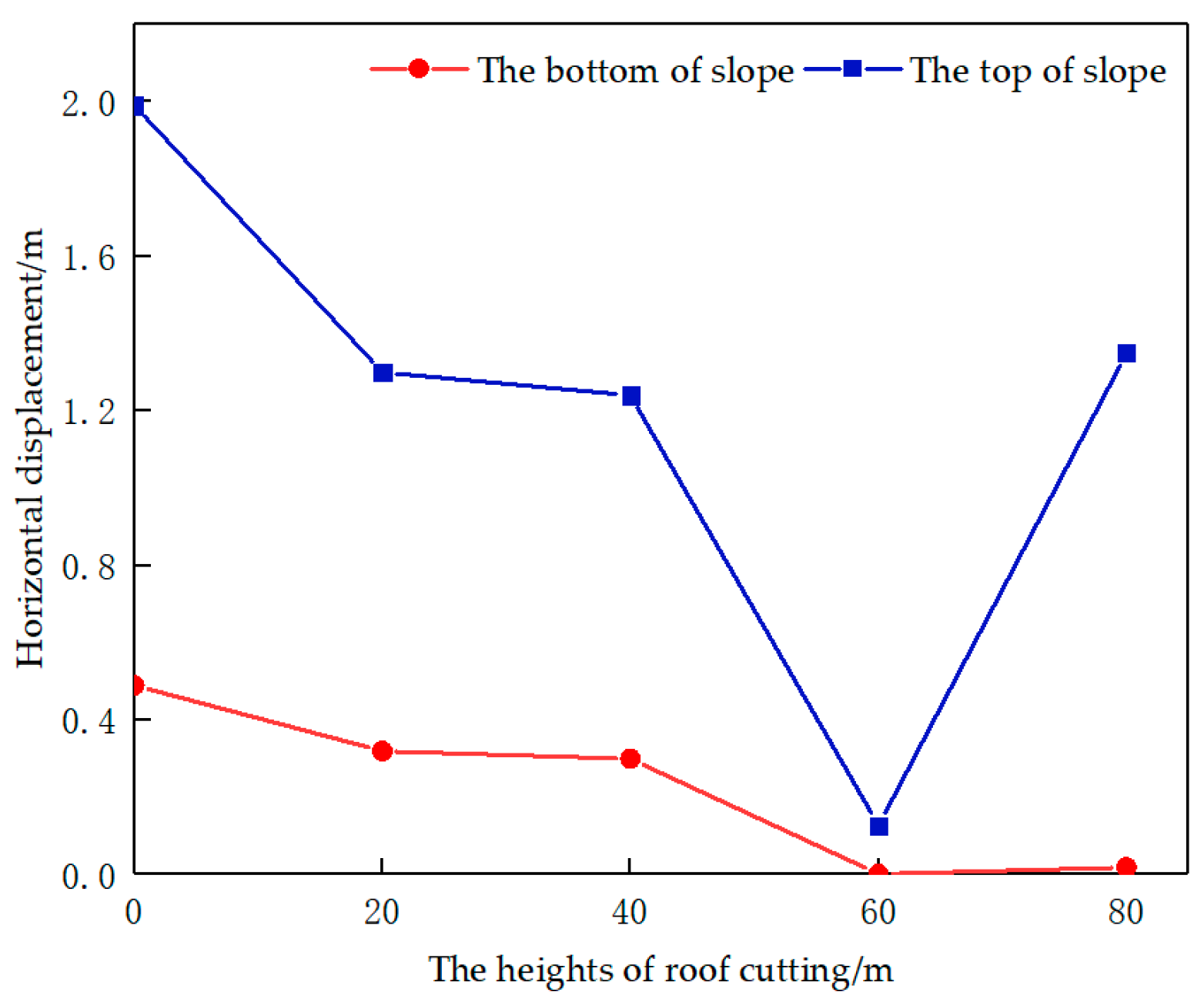
As can be seen from Figure 6, the horizontal displacement of the slope reached the maximum at the top and obtained the minimum at the bottom.
As shown in Figure 8, with the increase in the height of roof cutting, the horizontal displacement at the top of the slope and bottom of the slope first decreased and then increased. When the height of the roof cutting was 60 m, the horizontal displacement at the top of the slope reached the minimum of 0.127 m, and the minimum of 0.019 at the bottom.
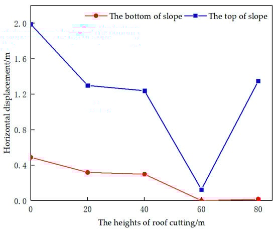
Figure 8.
Horizontal displacement of slope with different heights of roof cutting.
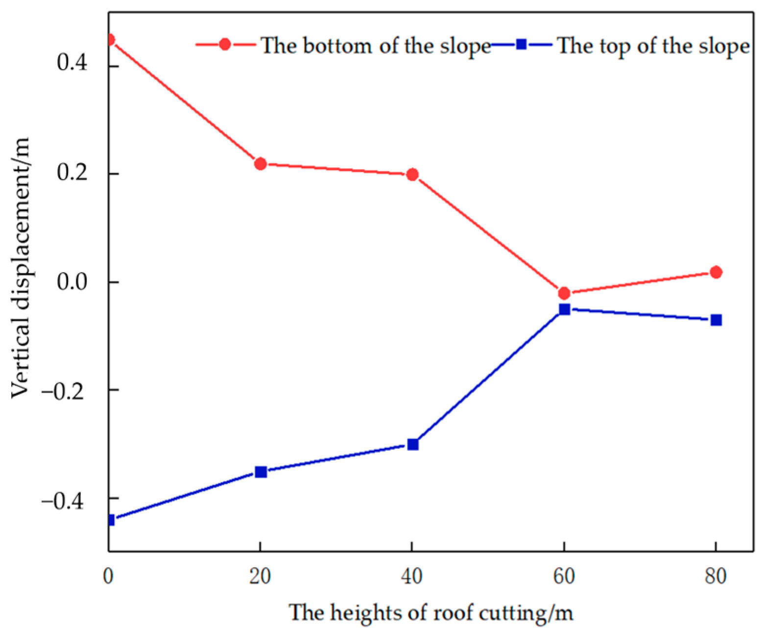
As shown in Figure 9, as the height of the roof cutting increased, the vertical displacement at the top and bottom of the slope first decreased and then increased. When the height of the roof cutting top was 60 m, the vertical displacement at the top of the slope reached the minimum of 0.049 m, and the minimum of 0.020 m at the bottom.
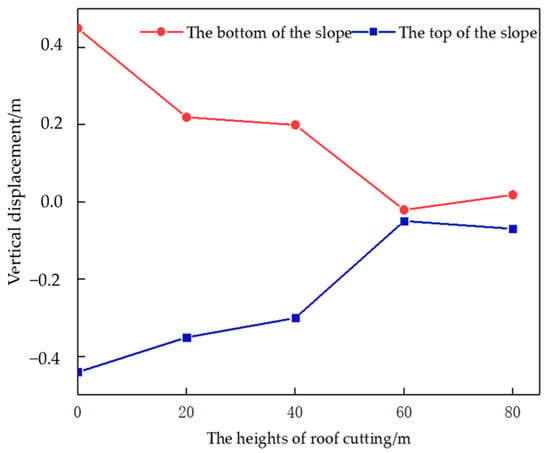
Figure 9.
Vertical displacement of slope with different heights of roof cutting.
During mining, there were rightward horizontal displacement and upward vertical displacement at the slope bottom, and rightward horizontal displacement and downward vertical displacement at the slope top. Therefore, the deformation and failure of the slope were manifested as the rotation to the goaf zone during mining.
With the increase in the height of the roof cutting, the displacement at the bottom and top of the slope decreased; the movement boundary shifted towards the cutting line; the stabilization zone expanded; and the rotation of the slope toward the goaf area decreased. When the height of the roof cutting top was 60 m, the slope was within the stable area, and the slope displacement as a whole was the minimum value. When the height of the roof cutting was 80 m, the rotation of the slope to the goaf area increased, and the control effect of the cutting height on the slope decreased.
It can be learned that roof cutting controls the slope mainly by suppressing the rotation of the rock mass from the rotary zone to the goaf zone. By cutting and crushing the top plates in the roof-cutting area, the overlaying rock formation fully collapses to fill and support the goaf zone, thereby reducing the vertical displacement of rock formation in the rotary area; at the same time, roof cutting causes the high-level rock formation to collapse along the cutting line. Consequently, the movement boundary shifts towards the goaf zone and expands the stable area, which makes the slope as a whole within the stable area. Meanwhile, the horizontal displacement of the rock formation in the rotary area is reduced, which suppresses the rotation of the rock formation in the rotary area to the goaf zone to achieve effective control of the slope.
5. Analysis of the Influence of Height of Roof Cutting on Crack Development
5.1. The Crack Development on the Lower Slope in Mining Without Roof Cutting
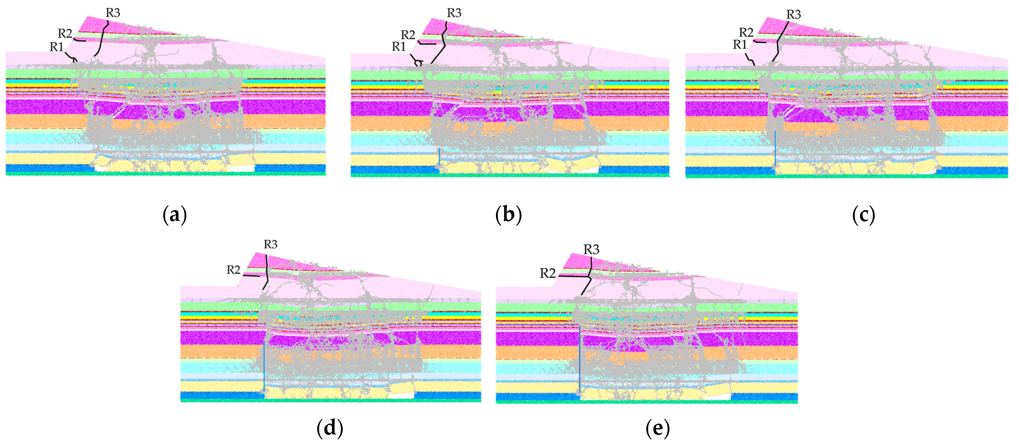
During mining at the working surface, the overlaying rock beneath the slope underwent damage to different extents due to the mining. The force chain diagram of the overlaying formation and the fracture development are shown in Figure 10.
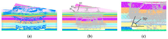
Figure 10.
Schematic diagram of fracture development in mining. (a) The tensile force chains; (b) the fractures; (c) the caving angle. R1 is the crack at the bottom of the slope; R2 is the slope surface crack; R3 is the crest crack.The blue lines represent the tensile force chains, the gray lines represent the fractures.
After back stopping the working surface, the separation cracks and breaking fractures developed significantly, resulting in the breaking and collapse of the immediate roof, which fell onto the floor of the goaf zone. The overlaying rock formation underwent arched collapse, at an angle of 70°. At this time, a tensile stress concentration area appeared in the rotation area (the blue area in Figure 10a). In the tensile stress concentration area, tensile crack R1 appeared at the slope bottom due to the tension on both sides and was connected to the working surface, as it is a penetrating rupture. The tensile rupture R2 appeared at the slope due to the tension on the lower side. During mining, the slope was affected by the tension of the rock formation in the rotary area and the traction of the rock formation in the collapse area. Tensile rupture R3 appeared at the slope top, which was a penetrating mining rupture. After the back stopping of the working surface, rupture R3 on the slope top extended downwards; the slope tended to rotate in the direction of propulsion; and the surface exhibited step-shaped damage.
5.2. The Influence of the Height of Roof Cutting on Stress and Fracture Development
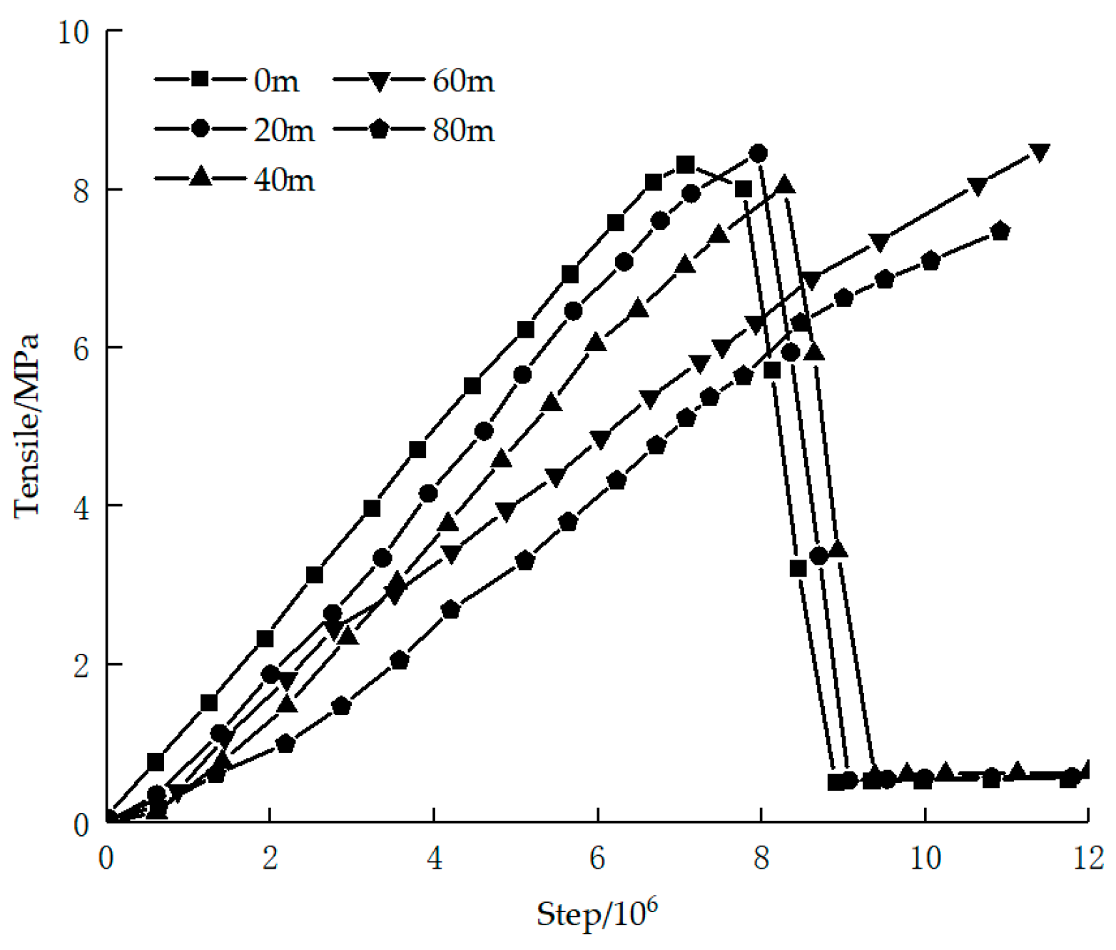
During mining, the tensile stress at the slope bottom changed, as shown in Figure 11. The change in tensile stress was divided into three stages: the growth stage, the stress release stage and the stabilization stage. In the early stage of mining, the tensile stress continued to increase until it reached the tensile strength at the slope bottom. Then, the rupture R1 appeared at the slope bottom to release the stress which was reduced to a minimum. As the mining continued, the tensile stress tended to stabilize.
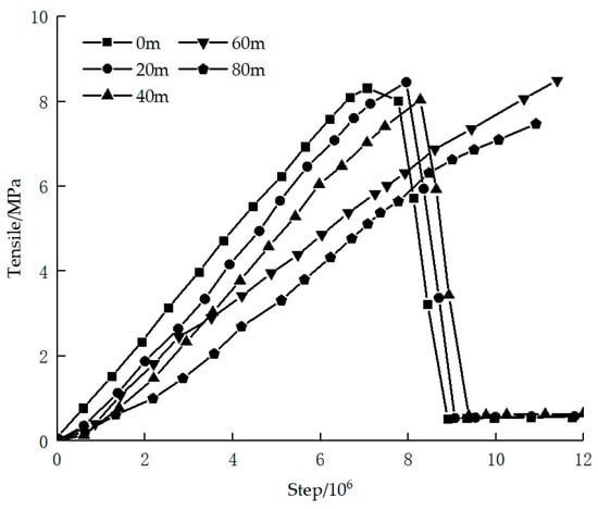
Figure 11.
Tension at slope bottom at different heights of roof cutting.
As shown in Figure 12 and Figure 13, after massive mining, there is a tensile stress concentration area in the slope within the rotation area. Coupled with the analysis of Figure 11, it can be seen that with the increase in the height of roof cutting, the tensile stress concentration area expanded while the growth rate of tensile stress in the growth stage decreased. When the height of roof cutting was 60 m, as the tensile stress at the slope bottom did not reach the tensile strength after mining, rupture R1 was not generated at the slope bottom to release the stress, and the damage at the slope bottom can be controlled. When the height of the roof cutting was 80 m, the control layer was cut off, and the strength of the control layer was destroyed, which resulted in excessive damage to the high-level rock formation. The slope rupture R2 was connected with slope rupture R3, which increased the risk of landslides.
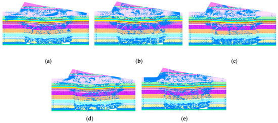
Figure 12.
Tensile stress chains at different heights of roof cutting: (a) 0 m; (b) 20 m; (c) 40 m; (d) 60 m; (e) 80 m. The blue lines represent the tensile force chains.
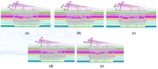
Figure 13.
Fractures development at different heights of roof cutting: (a) 0 m; (b) 20 m; (c) 40 m; (d) 60 m; (e) 80 m. The gray lines represent the fractures.
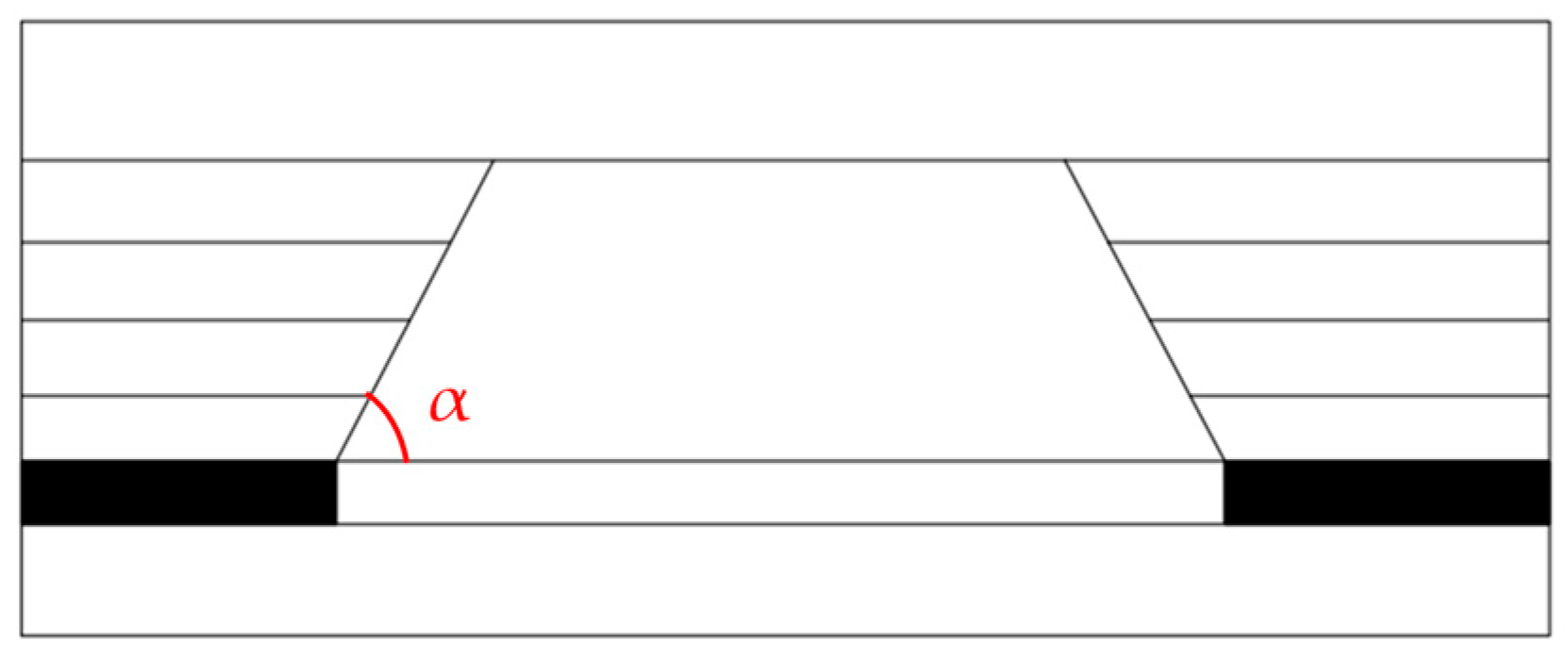
5.3. The Influence of the Height of Roof Cutting on the Angle of Collapse
As shown in Figure 14, the collapse angle is angle α formed between the fracture surface and the top plate level in the direction of the goaf zone after the collapse of the top plate.
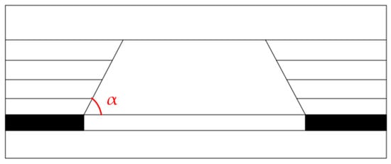
Figure 14.
Schematic diagram of collapse angle at different heights of roof cutting.
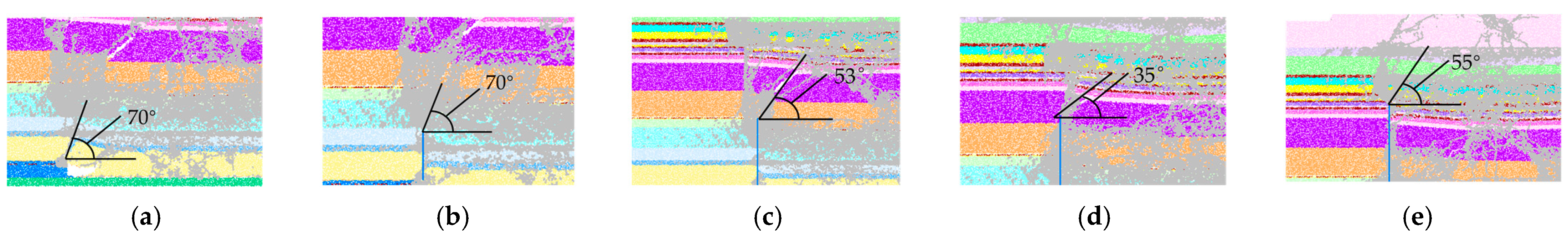
As shown in Figure 15, with the increase in the height of the roof cutting, the overlaying rock formation fully collapsed. When the height of roof cutting was 0, 20 m, 40 m, 60 m and 80 m, the collapse angle was 70°, 70°, 53°, 35° and 55°, respectively, and the collapse angle first decreased and then increased. When the height of the roof cutting was less than 60 m, as the height of the roof cutting increased, the collapse angle decreased, which resulted in a decrease in the rotation angle of rock formation from the rotation area to the goaf zone and the control of the slope. When the height of the roof cutting was 80 m, the integrity of the sandstone rock formation in the control layer was damaged, which exacerbated the collapse of the overlaying rock formation. As both the collapse angle and rotation angle of the slope within the rotation area increased, the control effect on the slope decreased.
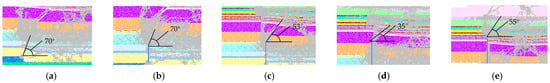
Figure 15.
Collapse angle of overlying rock formation at different heights of roof cutting: (a) 0 m; (b) 20 m; (c) 40 m; (d) 60 m; (e) 80 m. The gray lines represent the fractures.
According to the above analysis, the control effect of roof cutting on the overlaying rock formation and fracture development first increased and then decreased with the increase in the height of roof cutting. When the height of the roof cutting was less than 60 m, the overlaying rock formation fully collapsed, and the medium sandstone rock formation supported the slope, which effectively controlled the development of slope cracks. When the height of the roof cutting exceeded 60 m, the integrity of the medium sandstone rock formation was destroyed, and the support for the slope was weakened, which resulted in a weakened control effect on the slope. Judging from the development of slope cracks, the best effect was achieved when the height of the roof cutting was 60 m.
Hence, it can be learned that roof cutting controls the slope mainly by suppressing the rotation of the rock mass from the rotary zone to the goaf zone. With the increase in the height of roof cutting, the overlaying rock formation fully collapses and the collapse angle decreases, which reduces the rotation angle of the slope within the rotation area. In addition, there is slowed growth of tensile stress at the slope bottom, reduced peak tensile stress and suppressed development of cracks at the slope bottom, where the slope is controlled. When the integrity of the control layer is destroyed due to excessively high roof cutting, the fractures of the surface and top of the slope are easily connected to increase the risk of landslides.
6. Conclusions
This paper presents a case study of the 10101 working face of Xinyuan Coal Mine and its overlying slope. With the adoption of numerical simulation, a numerical simulation calculation model for different roof-cutting heights was constructed to study the influence of roof-cutting height on slope deformation and damage. The main conclusions are as follows:
- (1)
- During mining, the overlaying rock formation can be divided into three zones by displacement, namely, the subsidence area, the rotatory zone and the stable area. The subsidence area is below the collapse boundary, mainly characterized by vertical displacement with minor horizontal displacement towards the goaf zone; the rotation area is within the collapse and movement boundaries, where there is large vertical and horizontal displacement and the overall displacement was the rotation to the goaf zone; and the stable area is in the rock formation on the left side of the movement boundary, characterized by minor horizontal and vertical displacement, and the rock formations are overall stable.
- (2)
- A reasonable roof-cutting height should allow the cutting of hard rocks in overlaying formations without destroying the integrity of the control layer. The control layer supports the overlaying formation, especially the slope.
- (3)
- With the increase in the height of roof cutting, the movement boundary offsets towards the cutting line, and the stable area expands. When the roof-cutting height is 60 m, the movement boundary is outside the slope, which puts the slope within the stable area, and the slope deformation and failure are controlled; when the roof-cutting height is 80 m, the control layer is cut off, which exacerbates the slope deformation and failure.
- (4)
- With the increase in the roof-cutting height, the collapse angle of the overlaying rock formation decreases, and the growth rate of tensile stress at the slope bottom is not reached. However, at a roof-cutting height of 80 m, the ground experiences increased subsidence due to the removal of the control layer. As a result, the fractures at the surface and top of the slope are connected to increase the risk of landslides.
- (5)
- The control effect of roof cutting on the slope is mainly reflected in expanding the stable zone to cover the slope. After being cut and crushed, the overlaying formation in the roof-cutting area fully collapses along the cutting line, and the movement boundary also offsets toward the cutting line, so that the slope is within the stable area. At the same time, the collapse angle and the stress at the slope bottom are reduced to the development of cracks, thereby reducing the rotation of the rotation area to the goaf zone.
Author Contributions
Conceptualization, Z.C. and C.W.; methodology, M.W. and C.W.; software, Z.C.; validation, Z.C., C.W. and M.W.; formal analysis, Z.C.; investigation, Y.Y.; resources, Y.Y.; data curation, Z.C.; writing—original draft preparation, Z.C.; writing—review and editing, Z.C.; visualization, Z.C.; supervision, M.W.; project administration, M.W.; funding acquisition, Y.Y. All authors have read and agreed to the published version of the manuscript.
Funding
This research was funded by the National Natural Science Foundation of China (Grant No. 42302202) and the Shanxi Natural Science Foundation Project (Grant Nos. 20210302123124 and 202303021211057). The authors are grateful for this financial support.
Institutional Review Board Statement
Not applicable.
Informed Consent Statement
Not applicable.
Data Availability Statement
The data that support the findings of this study are available from the corresponding author upon reasonable request.
Conflicts of Interest
The authors declare no conflicts of interest.
References
- Li, J. Research on Controlling Deformation and Instability of Slopes Induced by the Movement of Overlying Strata in Underground Mining of Coal Underlying Slopes. Ph.D. Thesis, Inner Mongolia University of Science & Technology, Baotou, China, 2023. [Google Scholar]
- Li, J.; Wang, W.; Wang, C.; Wu, X. Study on the mechanism and control of slope instability slip induced by overburden migration in side coal mining. Coal Sci. Technol. 2025, 3, 1–16. [Google Scholar]
- Ding, X.; Li, F.; Fu, T.; Li, L. Overburden movement and failure law of coalface in end slope and the slope stability control method. J. China Coal Soc. 2021, 46, 2883–2894. [Google Scholar]
- Donati, D.; Stead, D.; Rabus, B.; Engelbrecht, J.; Clague, J.J.; Newman, S.D.; Francioni, M. Characterization of the Fels Landslide (Alaska) Using Combined Terrestrial, Aerial, and Satellite Remote Sensing Data. Remote Sens. 2023, 16, 117. [Google Scholar] [CrossRef]
- Ren, J.; Sun, P.; Zhang, S.; Li, R.; Wang, H.; Zhang, J. Experimental study on the failure mechanism of the Zhoujiashan landslide under the combined effect of rainfall and earthquake in Tianshui City, Northwest China. Bull. Eng. Geol. Environ. 2023, 82, 31–40. [Google Scholar] [CrossRef]
- Li, J.; Wang, W.; Wang, C.; Chen, S. Study on deformation and instability rule and control technology of slope in mining side wall coal mine. J. Saf. Environ. 2024, 24, 2157–2172. [Google Scholar]
- Zhang, Z. Study on Creep Properties of Weak Interlayer and Stability of Mine Slope under Acid Etching. Ph.D. Thesis, Wuhan University of Science and Technology, Wuhan, China, 2023. [Google Scholar]
- Tomasello, G.; Porcino, D.D. Earthquake-induced large deformations and failure mechanisms of silty sands in sloped ground conditions. Soil Dyn. Earthq. Eng. 2023, 173, 108056. [Google Scholar] [CrossRef]
- Silver, M.M.W.; Dugan, B. Cohesion, permeability, and slope failure dynamics: Implications for failure morphology and tsunamigenesis from benchtop flume experiments. Mar. Geol. 2023, 462, 107079. [Google Scholar] [CrossRef]
- Cook, M.E.; Brook, M.S.; Hamling, I.J.; Cave, M.; Tunnicliffe, J.F.; Holley, R. Investigating slow-moving shallow soil landslides using Sentinel-1 InSAR data in Gisborne, New Zealand. Landslides 2022, 20, 427–446. [Google Scholar] [CrossRef]
- Zhang, B.; Yang, K.; Zhao, Y.; Liu, Y.; Zhang, Y.; Liu, Y.; Ma, C.; Zhang, G. Centrifuge Model Tests on the Failure Behavior of Pile Foundation Under the Condition of Deep Non-uniform Settlement in Soil Slopes. Adv. Eng. Sci. 2020, 52, 94–99. [Google Scholar]
- Gunnell, Y.; Blondeau, S.; Jarman, D. Rock slope failure in the Southern Carpathians (Romania): Range-wide inventory and links with long-term mountain landscape evolution. Geomorphology 2022, 418, 108433. [Google Scholar] [CrossRef]
- Li, J.; Wang, W.; Wang, C. Research on Control of Slope Deformation, Failure and Instability Induced by Coal Mining on Side Wall. Coal Technol. 2024, 43, 140–146. [Google Scholar]
- Liu, G.; Huang, C.; Qi, X.; Wang, F. Reserch on deformation failure and macroscopic criteria of granite slope in Fengkai section of upper reaches of Xijiang River. Yangtze River 2021, 52, 96–101,113. [Google Scholar]
- Jiang, R.; Luo, J.; Pei, X.; Li, T.; Sun, H.; Li, Q. The characteristics and seepage stability analysis of complex toppling-sliding slope failure. J. Geol. Hazards Environ. Preserv. 2022, 33, 33–40. [Google Scholar]
- He, Z.; Jiang, G.; Feng, H.; Chen, H.; Guo, Y.; He, X.; Li, J. Investigation of deterioration characteristics and mechanisms of bedrock and overburden layer slope under seismic conditions after rainfall based on deformation. Rock Soil Mech. 2024, 45, 1789–1802. [Google Scholar]
- Fan, K.; Jing, C.; Niu, S.; Fan, D. Movement and Deformation Characteristics and Stability Analysis of Mining Slope at Different Inclination Angles. Saf. Coal Mines 2020, 51, 231–234. [Google Scholar]
- Mu, C.; Yu, X.; Zhang, D.; Mao, X. Analysis of deformation law of mining landslide in loess gullyarea. Saf. Coal Mines 2021, 52, 208–217. [Google Scholar]
- Pan, W.; Fu, L.; Li, X.; Zhang, X.; Han, G. Research on Mechanism of Madaling Landslide Caused by Coalmining in Guizhou Province Based on FLAC3D. Coal Eng. 2019, 51, 160–166. [Google Scholar]
- Kalililo, M.; Xia, Y. UDEC-based stability analysis of jointed bedding slope and slope parameter optimization suggestions: A case study. SN Appl. Sci. 2020, 2, 1943. [Google Scholar] [CrossRef]
- Dagdelen, K.; Traore, I. Open pit transition depth determination through global analysis of open pit and underground mine production scheduling. In Advances in Applied Strategic Mine Planning; Dimitrakopoulos, R., Ed.; Springer International Publishing: Cham, Switzerland, 2018; pp. 287–296. [Google Scholar]
- Wang, F.; Wang, D.; Yang, T.; Lv, B.; Gao, Y.; Deng, W.; Ji, Y.; Wang, X. Stability Analysis and Treatment of Anti-dip Rock Slope Interbedded with Soft and Hard Rock in Fushun West Open-pit Mine. Met. Mine 2022, 547, 162–169. [Google Scholar]
- Kelesoglu, M.K. The evaluation of three-dimensional effects on slope stability by the strength reduction method. KSCE J. Civ. Eng. 2016, 20, 229–242. [Google Scholar] [CrossRef]
- Hamm, N.A.S.; Hall, J.W.; Anderson, M.G. Variance based sensitivity analysis of the probability of hydrologically induced slope instability. Comput. Geosci. 2006, 32, 803–817. [Google Scholar] [CrossRef]
- Bourenane, H.; Bensalem, R.; Oubaiche, E.H.; Braham, M.; Meziani, A.A.; Bouhadad, Y.; Tebbouche, M.Y. The large deep-seated landslide induced by the March 12th, 2012 rainfall event in the city of Azazga, Northern Algeria: Deformation characteristics and failure mechanisms. Environ. Earth Sci. 2022, 81, 65–70. [Google Scholar] [CrossRef]
- Amagu, C.A.; Zhang, C.; Kodama, J.-I.; Shioya, K.; Yamaguchi, T.; Sainoki, A.; Fukuda, D.; Fujii, Y.; Sharifzadeh, M. Displacement Measurements and Numerical Analysis of Long-Term Rock Slope Deformation at Higashi-Shikagoe Limestone Quarry, Japan. Adv. Civ. Eng. 2021, 2021, 1316402. [Google Scholar] [CrossRef]
- Kaczmarek, Ł.; Dobak, P.; Szczepański, T.; Kiełbasiński, K. Triaxial creep tests of glacitectonically disturbed stiff clay – structural, strength, and slope stability aspects. Open Geosci. 2021, 13, 1118–1138. [Google Scholar] [CrossRef]
- Urmi, Z.A.; Saeidi, A.; Chavali, R.V.P.; Yerro, A. Failure mechanism, existing constitutive models and numerical modeling of landslides in sensitive clay: A review. Geoenviron. Disasters 2023, 10, 101–105. [Google Scholar] [CrossRef]
- He, M.; Zhu, G.; Guo, Z. Longwall mining “cutting cantilever beam theory” and 110 mining method in China—The third mining science innovation. J. Rock Mech. Geotech. Eng. 2015, 7, 483–492. [Google Scholar] [CrossRef]
- Gao, Y. Research on Key Problems of 110 Method in Thick Seam of Ningtiaota Coal Mine. Doctor’s Thesis, China University of Mining and Technology, Beijing, China, 2018. [Google Scholar]
- He, M.; Wang, Y.; Yang, J.; Zhou, P.; Gao, Q.; Gao, Y. Comparative analysis on stress field distributions in roof cutting non-pillar mining method and conventional mining method. J. China Coal Soc. 2018, 43, 626–637. [Google Scholar]
- He, M.; Gao, Y.; Yang, J.; Gong, W. An innovative approach for gob-side entry retaining in thick coal seam longwall mining. Energies 2017, 10, 1785. [Google Scholar] [CrossRef]
- Zhao, S.; Zhang, G.; Wang, W. Study on coordinated control technology of surrounding rock in self-made roadway without coalpillar in roof-cutting and pressure-relief of fully-mechanized caving face with deep buried thin bedrock. J. Henan Polytech. Univ. (Nat. Sci. Ed.) 2022, 41, 29–42. [Google Scholar]
- Sun, X.; Liu, X.; Liang, G.; Wang, D.; Jiang, Y. Key parameters of gob-side entry retaining formed by roof cut and pressure releasing in thin coal seams. Chin. J. Rock Mech. Eng. 2014, 33, 1449–1456. [Google Scholar]
- Sun, X.; Zhang, G.; Cai, F.; Yu, S. Asymmetric deformation mechanism within inclined rock strata induced by excavation in deep roadway and its controlling countermeasures. Chin. J. Rock Mech. Eng. 2009, 28, 1137–1143. [Google Scholar]
- Sun, X.; Zhang, Y.; Wei, B.; Guo, Z.; Yuan, S.; Chen, F. Design and application analysis of no-pillar mining technology control. Coal Technol. 2017, 36, 1–3. [Google Scholar]


Disclaimer/Publisher’s Note: The statements, opinions and data contained in all publications are solely those of the individual author(s) and contributor(s) and not of MDPI and/or the editor(s). MDPI and/or the editor(s) disclaim responsibility for any injury to people or property resulting from any ideas, methods, instructions or products referred to in the content. |
© 2025 by the authors. Licensee MDPI, Basel, Switzerland. This article is an open access article distributed under the terms and conditions of the Creative Commons Attribution (CC BY) license (https://creativecommons.org/licenses/by/4.0/).