Article

A Numerical Investigation of Enhanced Microfluidic Immunoassay by Multiple-Frequency Alternating-Current Electrothermal Convection

by
Qisheng Wu
1,2,
Shaohua Huang
2,
Shenghai Wang
2,
Xiying Zhou
3,
Yuxuan Shi
2,
Xiwei Zhou
2,
Xianwu Gong
2,
Ye Tao
4,* and
Weiyu Liu
2,*
1
Haojing College of Shaanxi University of Science and Technology, Xi’an 712046, China
2
School of Electronics and Control Engineering, Chang’an University, Xi’an 710064, China
3
School of Information Engineering, Chang’an University, Xi’an 710064, China
4
School of Mechatronics Engineering, Harbin Institute of Technology, Harbin 150001, China
*
Authors to whom correspondence should be addressed.
Appl. Sci. 2025, 15(9), 4748; https://doi.org/10.3390/app15094748
Submission received: 24 March 2025 / Revised: 17 April 2025 / Accepted: 22 April 2025 / Published: 24 April 2025

Abstract

:

Featured Application

The MET technique investigated herein can be applied to greatly boost the binding rate in microfluidic immunoassays driven purely by electrothermal flow, even with no external moving parts. This is vividly exhibited by the dynamic calculation results in the Supporting Movie, wherein the incoming antigen is transported horizontally and stirred laterally at the same time by the twisted streamlines of MET, leading to enhanced immune reaction with a quasi-semicircular depleted boundary layer on the functionalized electrode surface.

Abstract

Compared with traditional immunoassay methods, microfluidic immunoassay restricts the immune response in confined microchannels, significantly reducing sample consumption and improving reaction efficiency, making it worthy of widespread application. This paper proposes an exciting multi-frequency electrothermal flow (MET) technique by applying combined standing-wave and traveling-wave voltage signals with different oscillation frequencies to a three-period quadra-phase discrete electrode array, achieving rapid immunoreaction on functionalized electrode surfaces within straight microchannels, by virtue of horizontal pumping streamlines and transverse stirring vortices induced by nonlinear electrothermal convection. Under the approximation of a small temperature rise, a linear model describing the phenomenon of MET is derived. Although the time-averaged electrothermal volume force is a simple superposition of the electrostatic body force components at the two frequencies, the electro-thermal-flow field undergoes strong mutual coupling through the dual-component time-averaged Joule heat source term, further enhancing the intensity of Maxwell–Wagner smeared structural polarization and leading to mutual influence between the standing-wave electrothermal (SWET) and traveling-wave electrothermal (TWET) effects. Through thorough numerical simulation, the optimal working frequencies for SWET and TWET are determined, and the resulting synthetic MET flow field is directly utilized for microfluidic immunoassay. MET significantly promotes the binding kinetics on functionalized electrode surface by simultaneous global electrokinetic transport along channel length direction and local chaotic stirring of antigen samples near the reaction site, compared to the situation without flow activation. The MET investigated herein satisfies the requirements for early, rapid, and precise immunoassay of test samples on-site, showing great application prospects in remote areas with limited resources.

1. Introduction

Microfluidic technology, also known as Lab-on-a-Chip, is a technology that manipulates tiny fluids on the micrometer scale [1]. It achieves a high level of integration and automation of the experimental process by miniaturizing various functional units of the laboratory [2]. The main advantage of this technology is its ability to significantly reduce the consumption of reagents and samples, lower experimental costs, and improve the accuracy and repeatability of experiments [3]. Therefore, microfluidic technology has been widely used in fields such as biomedicine, chemical analysis, and environmental monitoring.
Immunoassay is a method of analyzing specimens using immunological techniques, and is mainly used in clinical testing to detect antibodies or antigenic substances in body fluids through antigen–antibody reactions [4]. The key to this detection method lies in the specific binding of antigens and antibodies. An antigen is a substance that can induce a specific immune response in the body, usually a protein with a molecular weight greater than 5000, while an antibody is an immunoglobulin that can specifically bind to antigens [5]. Performing immunoassays on a microfluidic platform can not only significantly save samples but also increase the speed and sensitivity of detection, which is of great significance for early disease diagnosis and biological research [6].
However, there are some obvious drawbacks to the current microfluidic immunoassay technology [7]. One of the most critical issues is that the detection process is often limited by the slow molecular diffusion process, which makes it difficult for antigens to rapidly reach the functionalized surface coated with antibody probes, thus affecting the efficiency and sensitivity of detection [8]. To overcome this limitation, convective acceleration technology has been introduced into microfluidic systems [9]. In microfluidic systems, electrohydrodynamics (EHDs) is a technology that uses an external electric field to exert electric forces on polarized fluid molecules, thereby generating active motion of the liquid medium and free particles monodispersed within [10]. This non-mechanical fluid driving method is particularly important in the field of microfluidics because it can provide precise fluid control [11].
Electric-field-driven fluid technology, including electro-osmotic and electrothermal flow, is a widely used method in microfluidic scenarios [12,13,14]. Electro-osmosis is a fluid motion caused by an electric field, which relies on the electromigration of mobile counterions within a thin electric double layer at a charged solid/electrolyte interface, thus generating a plug-like pump flow profile within a straight microchannel [15,16,17]. One of the main drawbacks of electro-osmotic streaming is that it is not effective in fluids with high electrical conductivity, and its driving effect is mainly limited to the vicinity of the fluid-solid interface. As a result, backflow is very likely to occur for a large distance away from charged channel walls [18,19]. Electrothermal flow, on the other hand, drives fluid motion through the thermal physical effects generated by an external electric field [20]. AC electrothermal flow (ACET) is particularly noteworthy because it originates from the action of the volume expansion force due to the smeared structural polarization of the fluid bulk of thermal-induced inhomogeneous electrical properties, which can effectively penetrate throughout the entire fluid volume, thereby producing uniform and effective electrokinetic flow with negligible backflow. AC electrothermal flow has two main categories: traveling-wave electrothermal flow (TWET) [21,22,23,24] and standing-wave electrothermal flow (SWET) [25,26,27,28]. TWET refers to the AC electric field applied to the electrodes propagating in the form of a traveling wave, thereby generating a continuous pumping flow field along the signal-phase transmission [29]. Meanwhile, SWET is induced by two oppositely polarized AC electrode terminals and usually behaves as a series of micro-vortices on top of the electrode array within the fluid channel [30].
In the present numerical investigation, a unique electroconvection method driven by multiple-frequency electrothermal flow (MET) is proposed, which delicately combines the advantages of TWET and SWET fluid motion. In our numerical model, by coupling the Joule heating source of the dual-frequency electric field, these two electrothermal flow effects will interact actively, thereby resulting in the patterns of twisted pumping and stirring streamlines of MET above a discrete electrode array. Our group has previously studied the phenomenon of MET actuated by multiple-frequency idealized sinusoidal voltage waves in the literature [28]. On the contrary, we propose in the current study to induce MET fluid motion on a four-phase discrete electrode array. Note that the specific flow behaviors of MET differ from each other under the condition of an ideal sine wave and the condition of a discrete-phase AC voltage. For instance, the flow velocity of SWET driven by an ideal sine wave vanishes to zero in the high-frequency limit due to a delicate compensation of a hydraulic pressure gradient in the vertical direction, while that caused by the four-phase AC powering persists well at high field frequencies. So, it is quite necessary to test the feasibility of utilizing a practical discrete electrode structure in driving active MET fluid motion in microfluidic channels. What is more, we further utilize the MET technology to enable simultaneous pumping and mixing of incoming nanoparticle samples, to accelerate the binding of free antigens to antibody probes fixed on the functionalized electrode surface (Please refer to the movie in the Supplementary Materials). This improves the efficiency and sensitivity of microfluidic immunoassays by activating active synthetic electrothermal flows, as demonstrated by systematic and comprehensive simulation studies. This paper aims to address the diffusion limitation issue in microfluidic immunoassays by introducing the technology of MET in the form of numerical simulation, further promoting the application of microfluidic chips in the biomedical field.

2. Materials and Methods

2.1. Device Geometry

We begin with a brief description of the geometry of the functional microfluidic device for causing active microscale immunoassay driven by electrothermal convection. One straight microfluidic channel, 30 μm in height and 390 μm in length, is arranged along the horizontal direction. Twelve identical metal strips are deposited on the channel bottom surface, which serves as a three-period discrete electrode array of four phase-shifted electrode strips in every repeating cycle. In the simulation model, for the convenience of result exhibition, it is assumed that the bottom discrete electrode array is coincidentally laid in the central portion of the device channel. Each conducting metal strip in the electrode array has a span of 10 μm, and the interelectrode gap size is fixed at 10 μm.
A composite sinusoidal voltage signal, which is composed of either a standing wave (SW) or a traveling wave (TW), or their combination (SW+TW), is externally imposed on the discrete electrode array by a multi-channel AC function generator. The SW voltage has a voltage amplitude of ASW and frequency fSW, and the voltage signal is sequentially phase-shifted by 180° along the consecutively distributed metal strips. On the other hand, the TW voltage has a voltage amplitude of ATW and frequency of fTW, and it propagates in the direction of the decreasing voltage phase towards downstream, namely, the adjacent electrodes are successively reduced by 90° in the voltage phase along the positive x axis.
It is supposed herein that only the sixth strip within the electrode array serves as the functional electrode, whose surface in direct contact with the buffer medium is coated with antibody probes. When all the electrodes are not activated by the AC power supply, there is no electrokinetic fluid motion; the antigen samples enter the channel inlet merely by pure thermal diffusion, as shown schematically in Figure 1A. In this situation, the diffusion motion of incoming analytes is extremely slow, so they cannot effectively reach the functionalized surface of the sixth electrode strip, resulting in a negligible immune reaction in the fluidic channel.
Switching on the hybrid AC voltage input to the electrode sequence, the dual-component Joule heating source causes an inhomogeneous temperature field, leading to anisotropic conductivity and dielectric constant of the bulk fluid phase. Under the action of multi-frequency alternating electric fields, the fluid medium undergoes Maxwell–Wagner structural polarization. The interaction between its heterogeneous electrical properties and the applied field induces space charge clouds within the bulk liquid. These charges experience Coulomb forces and dielectric forces imparted by the electric field, ultimately exciting multi-frequency electrothermal convection, as illustrated in Figure 1B. In this regime, incoming antigen molecules are simultaneously subjected to horizontal pumping and transverse stirring through the combined effects of electrothermal convection and molecular diffusion. Upon reaching the region above the sixth electrode strip, specific antigen–antibody binding reactions occur at the functionalized surface, forming a localized depletion diffusion boundary layer. The mechanism of MET convection significantly enhances immunobinding efficiency in the confined microchannel due to accelerated mass transport near reactive interfaces.

2.2. Theory of MET in Electrically Conductive Fluid

2.2.1. Quasi-Electrostatics

For alternating electric fields ϕ ( t ) = Re ( ϕ ˜ e j ω t ) , the complex electric field satisfies the electric current continuity condition [31]:
( σ + j ω ε ) E ˜ = 0
where E ˜ = ϕ ˜ is the phasor amplitude of the complex electric field, ε is the dielectric permittivity of the electrolyte, σ is the solution conductivity, f is the field frequency, and ω = 2πf is the angular frequency. If the liquid’s dielectric properties vary spatially, the divergence of the electric field can be derived from the previous equation [32]:
E ˜ = σ + j ω ε σ + j ω ε E ˜
As the local temperature of the buffer medium T changes, the electrical properties of the liquid would change linearly according to the known values of electric conductivity and permittivity at the reference temperature T0 [33]:
ε ( T ) = ε ( T 0 ) 1 + α ( T T 0 )
σ ( T ) = σ ( T 0 ) 1 + β ( T T 0 )
where the two thermal diffusivity coefficients α = ε T / ε = 0.004   K 1 and β = σ T / σ = 0.022   K 1 show that even though permittivity decreases as temperature increases, liquid electric conductivity rises at an even faster rate.
By integrating Equation (2) with the Gauss law equation, we derive a precise mathematical formula for the phasor amplitude of the induced spatial free charge density:
ρ ˜ f = ε E ˜ = ( σ ε ε σ ) σ + j ω ε E ˜
Observing that the electrical property varies with the temperature field, the first-order space free charge density can then be explicitly given by:
ρ ˜ f = σ ε ε σ σ + j ω ε E ˜ = ε ( α β ) 1 + j ω τ T E ˜
where τ = ε σ is the Debye relaxation time of the induced charge in the liquid bulk. Under the combined SW/TW electric signal, the temporary electrothermal body force density acting on each water element is essentially a sum of the Coulomb force from the induced free charge and the dielectric force from the polarized bound charge:
f ET ( t ) = Re ρ ˜ 1 e j ω 1 t + Re ρ ˜ 2 e j ω 2 t Re E ˜ 1 e j ω 1 t + Re E ˜ 2 e j ω 2 t 1 2 Re E ˜ 1 e j ω 1 t + E ˜ 2 e j ω 2 t Re E ˜ 1 e j ω 1 t + Re E ˜ 2 e j ω 2 t ε
where subscripts 1 and 2 represent the SW and TW components, respectively. For the purpose of simplification, we need to expand Equation (7) as follows:
f ET ( t ) = Re ρ ˜ 1 e j ω 1 t Re E ˜ 1 e j ω 1 t + Re ρ ˜ 1 e j ω 1 t Re E ˜ 2 e j ω 2 t + Re ρ ˜ 2 e j ω 2 t Re E ˜ 1 e j ω 1 t + Re ρ ˜ 2 e j ω 2 t Re E ˜ 2 e j ω 2 t 1 2 Re E ˜ 1 e j ω 1 t 2 + Re E ˜ 2 e j ω 2 t 2 + 2 Re E ˜ 1 e j ω 1 t Re E ˜ 2 e j ω 2 t ε
In the aforementioned equation, the interaction between the electric field and the induced charge of identical Fourier modes results in two subordinate effects: a steady electrostatic force component and an additional minor part oscillating at double the frequency of the SW/TW fields. Conversely, when the space charge density multiplies with an applied field of a different driving frequency (where ω1 does not equal ω2), this product consistently averages to zero over time, hence it does not contribute to the mean electrothermal flow effect. Consequently, employing a complex variable methodology allows for the derivation of the effective time-averaged electrothermal body force from Equation (8) as given by:
f ET ( t ) = 1 2 Re ρ ˜ 1 E ˜ 1 * + ρ ˜ 2 E ˜ 2 * 1 4 E ˜ 1 E ˜ 1 * + E ˜ 2 E ˜ 2 * ε = 1 2 ε Re ( α β ) 1 + j ω 1 τ T E ˜ 1 E ˜ 1 * + ( α β ) 1 + j ω 2 τ T E ˜ 2 E ˜ 2 * α 2 E ˜ 1 E ˜ 1 * + E ˜ 2 E ˜ 2 * T
where denotes the time-averaging operation, and the symbol * represents the complex conjugate.

2.2.2. Heat Transfer

Within the entire microsystem, the steady-state energy balance equation, which includes the Fourier heat conduction and electric heat generation effects, needs to be solved:
( k f T ) + 1 2 σ ( E ˜ 1 E ˜ 1 * + E ˜ 2 E ˜ 2 * ) = 0
( k P D M S T ) = 0
( k S i T ) = 0
In this analysis, we consider the thermal conductivities of the liquid medium, PDMS wall, and silicon substrate, denoted as k f = 0.6   W m - 1 K - 1 , k P D M S = 0.2   W m - 1 K - 1 , and k S i = 140   W m - 1 K - 1 , respectively. The time-averaged Joule heating term 1 2 σ m ( T ) ( E ˜ 1 E ˜ 1 * + E ˜ 2 E ˜ 2 * ) in Equation (10) is derived using the same method as invoked in Equation (9) and is the sole heat source. Other solid domains show no significant electric heat generation due to their extremely low electric conductivity.

2.2.3. Electrothermal Convection

The resultant mean electrothermal force density is inserted into the incompressible Navier–Stokes equation for water-based Newtonian fluids:
p + η 2 u + 1 2 ε Re ( α β ) 1 + j ω 1 τ T E ˜ 1 E ˜ 1 * + ( α β ) 1 + j ω 2 τ T E ˜ 2 E ˜ 2 * 1 2 α E ˜ 1 E ˜ 1 * + E ˜ 2 E ˜ 2 * T = 0
u = 0
where p denotes the hydrostatic pressure, u the flow velocity field due to the action of MET, and η = 0.001 Pa·s is the liquid dynamic viscosity.

2.2.4. Mass Transfer of Antigen and Immune Response Enhancement

The antigen sample is freely suspended in the buffer medium, and its concentration field obeys the conventional convection-diffusion equation:
c t + J = 0
J = u c D c
where c represents the concentration of antigens in the bulk liquid, and D = 10 11 m 2 s - 1 is the antigen mass diffusivity.
It can be assumed that the specific binding interaction between the antigens in solution and the antibodies immobilized on the functionalized electrode surface follows a first-order Langmuir adsorption model:
B t = k o n C w ( R T B ) k o f f B
where B denotes the surface concentration of the antigen absorbed on the reaction surface, with units in mol·m−2, and k o n and   k o f f stand for the association rate constant and the dissociation rate constant, respectively. C w is the volumetric concentration of the free antigen in the immediate vicinity of the reaction surface, and R T is the surface concentration of the immobilized antibody probe with unit in mol·m−2. To appraise the feasibility of MET-induced fluid stirring and pumping in enhancing the antigen–antibody binding rate, we define the transient binding enhancement factor as Be(t) = BeV(t)/B0(t), where BV(t) and B0(t) are the bound antigen concentrations with and without applying external hybrid AC electric fields, respectively. It is reported that the binding rate strongly relies on the dimensionless Damkohler number:
D a = k o n R T H C D
which measures the relative magnitude of the reaction speed to the diffusion speed. The Da number is often used to determine whether the biosensor is limited by diffusion or by reaction. If the reaction rate is faster than the diffusion transport of the target analyte to the sensor surface, the entire binding process is diffusion-limited. Conversely, the binding rate will be reaction-limited when the analyte diffusion is rapid but the reaction speed cannot keep up with the diffusion rate.

2.3. Numerical Simulation

A commercial software package, COMSOL Multiphysics (version 6.2 update 2), which is based on the finite element method, is used herein to numerically analyze the flow field of MET driven by a phase-shifted discrete electrode array and its application in enhancing on-chip immune response by simultaneously transporting and stirring antigens in a microchannel. The 2D computational domain is composed of a straight channel embedding a thin layer of 12 metal strips (see Section 2.1 for detailed geometry size). The detailed interfacial conditions for each governing equation are given below.

2.3.1. Dual Frequency AC Electric Fields in a Hybrid SW and TW Excitation

The charge conservation equation, Equation (1), is computed to obtain the electrostatic potential field induced by the applied SW and TW voltage wave in time harmonic steady-state, respectively. Fixed potential phasor is defined on each electrode unit in the metal strip array placed on the channel bottom surface for producing sinusoidal SW and TW electric fields:
ϕ 1 = A SW , A SW , A SW , A SW
ϕ 2 = A TW , j A TW , A SW , j A SW
where ASW and ATW are the voltage amplitudes of the imposed SW and TW signals, respectively, and j is the imaginary unit. The ellipses in Equations (15) and (16) indicate the repeating nature of the applied electric potential within each signal wavelength towards downstream. In addition, a normal component of the electrostatic potential gradient vanishes on the insulating channel walls.

2.3.2. Thermal Diffusion in the Fluidic Device

Then, the set of thermal diffusion equations, Equations (10)–(12), is solved in the whole microfluidic chip, taking into account the action of dual-component Joule heating source inside the bulk solution. Continuity of both the temperature value and normal thermal flux is implemented at all the inner interfaces of the functional MET microdevice. Ambient temperature T = T0 = 293.15 K is prescribed on both the top surface of the PDMS lid and the bottom surface of the silicon base, while adiabatic condition is applied on all other external boundaries.

2.3.3. Electrokinetic Fluid Motion Driven by MET

Subsequently, the modified full Stokes equation, Equations (13) and (14), containing a composite electrostatic force density, is computed to obtain the flow field driven by MET inside the liquid solution. No slip and no penetration are imposed on all the channel boundaries. Both the left and right ends of the fluid channel are assigned to serve as open ports with zero gauge pressure, so as to guarantee that any net fluid motion is solely induced by the action of MET.

2.3.4. Transient Immune Response

The governing equations of Equations (15) and (17) are calculated simultaneously in the fluid domain and on the polarizable surface of sixth metal strip, respectively, to get the transient bulk concentration of incoming antigen and surface concentration of antigen bound to the functionalized surface due to immune response, both of which depend strongly on one another in the time domain. A fixed concentration of c = c0 = 0.1 nM is designated at the left channel entrance. A normal diffusion flux D C n = B t is designated on the reaction interface for representing the loss of antigen volumetric concentration in the immediate vicinity of the sixth electrode strip due to the binding reaction. All other channel walls, as well as the right channel exit, forbid any diffusion motion in the normal direction.

3. Results and Discussion

3.1. Numerical Characterization of Electrothermal Induced Convection

In this chapter, firstly, the electrothermal induced flows driven by the SW and TW voltage signals are studied by direct numerical analysis, and the ideal working state is found through conducting simulations in a wide frequency range, with the aim of finding the ideal working frequencies of SWET and TWET, respectively. Secondly, based on the aforementioned theoretical foundation and the exploration of the ideal working frequencies of SWET and TWET, the fluid motion of MET under combined SW and TW voltage actuation is calculated, and the MET is proved to promote simultaneous lateral mixing and horizontal pumping of bulk electrolyte on top of a three-cycle discrete four-phase microelectrode array configuration. At the same time, the key parameters affecting the flow behavior of MET are explored, which initially delineates the effective parameter range for achieving the subsequent immunoreaction kinetic application.

3.1.1. Standing-Wave Electrothermal Fluid Motion

A standing wave has a phase difference of 180° in the applied harmonic voltage between neighboring electrodes of opposite polarity. Every electrode can be approximated as a point charge under this condition, so the in-phase electric field is quite similar to the electric field generated by a static point charge. From the space distribution of the standing-wave electric field shown in Figure 1A, we can treat the voltage gradient generated by the standing-wave signal for the zero-order electric field with uniform conductivity, since there is no evident deflection of equipotential lines. When the standing-wave voltage signal is applied to the discrete electrode array, a large amount of Joule heat is generated in the bulk electrolyte and then diffused into the liquid solution and solid substrate due to the resistive effect. The temperature field induced by electric heat generation in the liquid solution is shown in Figure 2B, with the electrode surface behaving as the low temperature region.
The fluid is subjected to time-averaged Joule heating to produce an internal temperature gradient, and thus a continuous conductivity gradient across the channel depth direction. Due to the objective constraints of the full electric current continuity condition, the interaction of the electrical property gradient with the imposed standing-wave electric field inevitably leads to the in-phase smeared structural polarization, generating an induced space charge cloud, which imparts an electrostatic force density to the fluid bulk and drives the SWET flow field in the form of a series of counter-rotating micro-vortices.
As shown in Figure 2C–E, the distribution of time-averaged SWET flow field in space is analyzed for three different field frequencies. In the low frequency limit of f = 100 kHz, as dominated by the Coulomb force, fluid of higher conductivity is transported by the SWET forcing to occupy the region of larger electric field strength. This is in good agreement with Figure 2C, which shows the fluid is dragged from the top of the electrode gap of the largest temperature elevation to the center of the electrode surface, and finally forms a series of closed eddies in counter-rotating directions. However, different from the repeating flow pattern actuated by periodic electrode structures, the SWET flow field on top of the finite electrode array presents a larger vortex on its two sides, mainly due to the electric field end effects on electrothermal induced bulk polarization. When the field frequency equals fACET (the critical frequency for flow reversal in SWET, fACET, is 11 times the Debye relaxation frequency fMW = σ / 2 π ε ), as shown in Figure 2D, the flow velocity originated by SWET decays dramatically, and it is well known that this serves as the critical frequency point beyond which the in-phase electrothermal streaming reverses in flow direction, and the flow velocity reaches a global minimum as indicated by the frequency-flow velocity relationship diagram in Figure 3. When the imposed signal frequency further increases and attains 10 GHz exceeding well the value of fACET, the induced free charge disappears and only the polarized bound charge exists due to a special charge relaxation process, and the electrothermal fluid motion is dominated by dielectric force acting on a permittivity gradient, wherein the fluid medium of lower polarizability (lower permittivity due to a higher temperature elevation at electrode edges) is repelled to the region of a weaker electric field strength (top of the electrode spacing), as evidenced by a high-frequency flow reversal (Figure 2E) compared to the low-frequency situation (Figure 2C). In addition, the SWET flow velocity at 10 GHz under evident charge relaxation is much smaller than that at 100 kHz.
Through the previous qualitative analysis of standing-wave induced electrothermal convection, it can be seen that the SWET flow rate above the center of each electrode unit is basically zero due to the counteraction of two symmetric electrokinetic vortices in opposite streaming directions. At the same time, if the solution contains biomolecules, they will be concentrated in the region of slow flow rate on top of the electrodes under SWET convective mixing, which greatly improves the probability of the active immunoreaction between the free antigen analyte and antibody probe fixed on functionalized metal surfaces. In order to simplify the work of the parameter optimization process in the calibration experiments and to explore the influence of different experimental parameters on the SWET bulk convection and interfacial immunoreaction kinetics, it is necessary to perform a parametric scanning of the field frequency of the imposed SW signal to preliminarily determine the specific frequency range within which the optimal device performance is located.
Figure 2F,G shows the flow rate and vorticity magnitude of SWET as a function of the SW signal frequency fsw under a constant driving voltage, respectively. As the frequency is scanned from 103 to 1011 Hz, it can be seen from Figure 3 that the flow rate and vorticity both adopt large values in the low frequency conductivity plateau for field frequency much lower than the critical relaxation frequency f = 11 fMW. However, when the frequency increases approaches it, the flow velocity and vortex vorticity drop rapidly to a minimum value, then reverse in variation trend, grow with frequency, and maintain a stable permittivity plateau in the high frequency range for frequencies exceeding well fACET.
Based on the above simulation results, when the frequency of the applied SW voltage signal is between 1 kHz and 10 MHz, the flow rate due to the action of SWET has a relatively high level, and the inhomogeneous bulk fluid is mainly subjected to Coulomb force acting on the induced free charge, which complies with the polarization trait of enhanced microfluidic immunoassay driven by active electrothermal convection.

3.1.2. Traveling-Wave Induced Electrothermal Flow

A traveling-wave field is the electric field of spatial phase variations generated by a linear electrode track with a given phase difference (e.g., 90°) between neighboring electrodes. The complex amplitude method is used here to analyze the phase-shifted electric field in the simulation of traveling-wave induced electroconvection, and the complex electric field is decomposed into real and imaginary parts, as shown in Figure 3A and Figure 3B, respectively. The same electrodes differ by 90° in the distribution of the real and imaginary parts of the sinusoidal voltage, namely, they are equally separated by an electrode gap. Figure 3C shows the temperature field generated by TWET. Referring to the temperature field generated by SWET (Figure 2B), it can be found that the difference between the temperature field profile and maximum temperature elevation in TWET and SWET is not large at the same voltage amplitude. A low temperature region is located right on the surface of the discrete electrode array, which corresponds to a smaller electrical conductivity of liquid molecules, and the temperature value increases gently with a larger vertical distance from the electrode surface on the channel bottom surface.
Figure 3D–I shows the pumping effect generated by traveling-wave signals of different oscillating frequencies, and it can be found that the electrokinetic transport direction of the liquid medium is always in the direction of the traveling wave. The reason behind this is the formation of a positive conductivity gradient pointing from the perfectly polarizable surface of metal electrodes to the channel top wall, so the current TWET device serves as an attraction-type pump, wherein the TWET pumping force is in the same direction as the propagation direction of the traveling wave. When f = 1 kHz, as shown in Figure 3D, no obvious pumping effect is found in the bulk fluid, and instead, a series of small electrothermal vortices are formed on top of the electrode array, mainly due to the in-phase induced polarization. Increasing the TW frequency to 1 MHz, as shown in Figure 3E, the pumping effect is enhanced within the working fluid, but the vortex shedding is still significant. When f is increased to 10 MHz, as shown in Figure 3F, the pumping behavior of the liquid medium is significant, and the vortex flow obviously disappears, but there are still electrothermal vortices induced near the left channel inlet. Continue to raise the TW signal frequency to fMW = 22.5 MHz, as shown in Figure 3G. At this time, the pumping motion due to out-of-phase electrothermal induced polarization reaches the ideal working state, the horizontal pump flow rate is high, and no obvious vortex is found in the transversal direction. When f is raised to 1 GHz, as shown in Figure 3H, the flow rate decreases severely, and vortices begin to appear at both the entrance and exit of the discrete electrode array. For f = 10 GHz, as shown in Figure 3I, the liquid pump motion tends to vanish, and two huge vortices of opposite flow direction with geometric symmetry are formed at the channel inlet and outlet.
Through the numerical analysis of TWET fluid motion, the out-of-phase TWET pumping force achieves unidirectional delivery of the incoming analyte. If biomolecules are added into the buffer solution, rapid convective transport of the incoming particle samples can be achieved by the TWET pumping effect, and therefore avoiding the slow thermal diffusion in a concentration gradient, greatly improving immune adsorption dynamics on functionalized interfaces in microfluidic channels. To find the ideal working frequency, a COMSOL parametric sweep is conducted to arrive at the conclusion. Figure 4A,B show the horizontal pump flow velocity, overall flow rate, and rotating vorticity of the TWET fluid motion within a broad frequency range. At intermediate frequencies, it can be seen that the overall electrothermal flow rate is almost consistent with the horizontal pump flow rate, which attains an out-of-phase relaxation peak with the largest pump performance in the absence of lateral convective stirring. This frequency point of maximum pump motion is called the ideal pump frequency f = fMW by taking into account the out-of-phase smeared structural polarization of inhomogeneous liquid solution subjected to a TW field. On the contrary, when the horizontal pump flow rate is almost zero at low TW field frequencies, there is a strong lateral stirring flow rate, and the vorticity magnitude becomes much higher. However, it only reaches 500, compared to the SWET flow with vorticity up to 1800. At high frequencies, both the horizontal and lateral TWET velocity are weak, and the vorticity is low as well due to the occurrence of bulk ionic screening. Accordingly, the TWET actuation mode is more likely to pump for unidirectional sample delivery at intermediate frequencies, and the SWET counterpart is more likely to produce eddies for chaotic analyte stirring in the low-frequency range. To conclude, when the frequency of the imposed TW voltage wave equals fMW, the pumping effect of TWET fluid motion is the most apparent, and electrothermal eddies no longer exist. This conforms to the expectation of boosted analyte delivery in microfluidic immunoassay to the best extent.

3.1.3. Multiple-Frequency Electrothermal Induced Convection

The flow behaviors of SWET and TWET have been analyzed sequentially, and their ideal working conditions were obtained. Since the characteristic operating frequencies of SWET and TWET convection are significantly different, the cross product of the induced space charge with the in situ electric field of another actuating frequency always averages to zero over time. In this way, SWET and TWET can be added together to the polarizable electrolyte solution at their respective ideal frequency to engender the phenomenon of MET convection, in which the SW and TW electric field is mutually coupled through the joint action of dual-component Joule heat to given rise to a new flow state, and the ideal synthetic fluid motion driven by hybrid voltage signals is obtainable through direct numerical simulation.
Figure 5A–C shows the calculation results of the MET flow field at the ideal frequency combination of fsw = 100 khz and ftw = fMW, under varying SW voltages and a constant TW voltage Atw = 6 V. As shown in Figure 5A, for Asw = 2 V and Atw = 6 V, a brisk pump motion is induced by out-of-phase electrothermal effect in the working fluid, with only insignificant vortices at the inlet. Raising the SW voltage to Asw = 6 V with TW voltage kept unchanged, as shown in Figure 5B, chaotic vortices appear on electrode surfaces, the lateral stirring flow rate is greatly enhanced, and the horizontal flow rate is weakened. By further raising Asw to 12 V, as shown in Figure 5C, the pump effect almost disappears, and the resulting MET flow field is dominated by in-phase electrothermal micro-vortices.
The simulation results of parameterized scanning of SW voltage and TW voltage for given driving frequencies are exhibited in Figure 5D–I. Variation of the voltage amplitude ranging from 0 V to 12 V is defined in the numerical calculation, respectively, to explore the influence that SW voltage and TW voltage have on the temperature rise, pump capability, and rotating vorticity of the resulting MET fluid motion. In Figure 5D,E, the maximum temperature rise within the fluid increases with both SW and TW voltages, but under the same voltage magnitude of SW and TW signals, the temperature elevation is almost the same, so the two distinct electric field components have essentially similar contributions to the dual-component electric heat generation. Due to the small degree of temperature elevation of up to 6 K, the imposed multiple frequency AC signals will not affect the biological activity of target molecules such as antibodies. As shown in Figure 5F,G, the horizontal pump speed from MET rises from 125 μm·s−1 to 520 μm·s−1 when the amplitude of SW voltage is elevated from 0 to 12 V with a difference of 4.25 times, while the pump speed increases from 0 to 2100 μm·s−1 when the TW voltage is enhanced from 0 to 12 V with a difference of infinity times. Similarly, as shown in Figure 5H,I, for an adjustment of the flow vorticity for chaotic mixing along channel transversal direction, a change in the SW voltage is much more useful than controlling the TW voltage, since the vorticity magnitude of MET changes by nearly 50 times with ASW, but by merely 6 times with ATW, increasing from 0 to 12 V.
By analyzing the MET flow field under the condition of ideal frequency combination, it is easier to control the flow vorticity of MET by adjusting Asw, and the pump speed of MET by adjusting Atw, respectively, but the excessive temperature rise caused by too large voltage will exert an adverse influence on the biological activity of the antigen and antibody as well as the overall impedance characteristics of the saline solution accommodating on-chip immune reaction. In practical experiments, the effect of each AC signal should be considered carefully to select the appropriate voltage parameters. Even so, the MET flow mode under Asw = 6 V and Atw = 6 V has a good agreement with the target of enhanced microfluidic immunoassay. In this circumstance, both the pumping speed and stirring vorticity of MET have an appropriate intensity, and the peak temperature rise of less than 10 K will not cause significant damage to the biological samples suspended in the buffer solution.

3.2. Enhanced Microfluidic Immunoassay by Applying MET

From previous analysis, we found that SWET mainly enhances local mixing to make the antigen more uniformly distributed within the reaction area. TWET drives the horizontal flow of the liquid through the Coulombic forces generated by a high-frequency traveling-wave electric field to increase the delivery rate of the antigen along the length of the channel. In microfluidic immunoassays, MET convection combines the respective features of SWET and TWET to evolve into an efficient kinetic model of binding reaction with simultaneous horizontal transport and transversal stirring of incoming antigens. Our simulation study will show that MET can effectively enhance the antigen–antibody binding efficiency by optimizing the dual signal frequency and voltage combination.

3.2.1. Transient Immune Response Under MET

In the simulation of on-chip antigen–antibody binding kinetics, it is assumed that the antibody probes are coated on the sixth electrode from left to right. That is, only the sixth metal strip serves as the functionalized surface where immunoassay is possible to occur, while all other electrodes are bare and in direct contact with the electrolyte. Antigens are freely suspended in the buffer medium and initially released from the left inlet with no external forces.
The concentration distribution of incoming antigens within the straight channel at t = 600 s, due to the action of MET, is shown in Figure 6 on application of the hybrid SW/TW signal of different voltage amplitudes at the ideal frequency combination. Under Vsw = 0 V and Vtw = 0 V, as shown in Figure 6A, it can be found that the incoming analyte fails to move to the surface of the sixth electrode under pure thermal diffusion even at t = 600 s, and the concentration of antigen on the functionalized surface is close to 0. Under Vsw = 6 V and Vtw = 0 V, as shown in Figure 6B, a series of lateral SWET vortices appear in the solution with no axial pump flow component at t = 600 s, so the concentration of antigen on the surface of the sixth electrode strip approaches zero once again. Under Vsw = 0 V and Vtw = 6 V, as shown in Figure 6C, since the TWET pump motion is induced along the channel length direction, the confined space of the microfluidic channel is filled with antigen at t = 600 s. Although a decrease in antigen concentration occurs near the reaction surface, the thickness of the depletion boundary layer is relatively thin due to a paucity in convective mixing. Under Vsw = 6 V and Vtw = 6 V, both global horizontal pumping and local transverse vortex stirring appeared in the solution, not only the channel volume was filled with antigens that were constantly delivered downstream by TWET pump force, but the local SWET vortex also made the range of the depletion boundary layer of antigen larger on the functionalized surface of the sixth electrode strip, which possesses a semicircular contour and a more homogeneous depleted antigen distribution, indicating the occurrence of an efficient binding reaction.
As in Figure 6E, the dynamic evolution of antigen concentration adsorbed on the functionalized surface B is quantitatively characterized from 0 to 600 s, which can more intuitively reflect the promotion effect of MET convection on microscale binding kinetics. When Vsw = 0 V and Vtw = 0 V, the surface antigen concentration B does not change with t and is still almost zero at t = 600 s under no electrothermal fluid motion. When Vsw = 6 V and Vtw = 0 V, B appears to rise, but is still very small without TWET transportation. When Vsw = 0 V and VTw = 6 V, B grows significantly with time, and B/Rt attains 0.0112 at t = 600 s due to the action of the TWET pump motion. When Vsw = 6 V and Vtw = 6 V, the enhancement of B with time is the most obvious, and B/Rt rises to 0.0163 at t = 600 s, since the incoming antigen sample is stirred by lateral SWET eddies and transported by horizontal TWET pump streamlines at the same time. As a result, the dynamic binding efficiency between free antigen and fixed antibody probe can only be significantly enhanced by fully combining the respective flow properties of SWET and TWET by using MET under dual-frequency harmonic actuation. As for the time-dependent immune reaction kinetics, in our simulation, at t = 600 s, an active hydrodynamic motion of antigen induced by electrothermal convection results in significantly higher binding concentrations on the functionalized electrode surface than that in the control experiment free from external AC forcing, and the incoming analyte is distributed more homogeneously within the reaction area. In addition, although the bound antigen concentration increases with time (Figure 6E), it will finally become stable (not shown, but can be deduced from Equation (17) under a rather small CW value in the quasi-steady state) as long as the voltage signal is maintained.

3.2.2. Frequency Effect on Binding Reaction Efficiency

We have learned that harmonic electric fields of different frequencies have effects on stirring eddies and pump streamlines produced by SWET and TWET, and then we investigate the influence that the standing-wave and traveling-wave field frequencies on the enhancement factor of antigen concentration absorbed on the reaction surface (Be(t = 600 s)). In this situation, the voltage amplitudes are kept constant at Vsw = 6 V and Vtw = 6 V, and when varying one of the dual electric field frequencies, the other one is set at the ideal operating frequency. The voltage frequency exerts a substantial influence on the interfacial binding kinetics, mainly through an adjustment in the specific flow state of electrothermal induced convection.
Figure 7A shows the variation trend of Be at varying SW frequencies. The SWET flow field is dominated by the Coulomb force at low frequencies (fsw < fACET), with significant electrothermal eddies, and Be adopts its maximum value in the low-frequency range. However, since the dielectric force governs the flow behavior of SWET at high frequencies (fsw > fACET), the electrothermal whirlpools not only reverse but also decay appreciably with respect to the low-frequency situation, and Be starts to decrease and then remains constant in the high-frequency limit. Therefore, to enhance the microfluidic immunoassay as far as we can, the SW field frequency used in MET ought to be close to the low-frequency limit.
In Figure 7B, the value of Be at t = 600 s decreases when the field frequency of the TW signal deviates from the ideal pump frequency, and is at a high value near the intermediate critical frequency. The peak of Be does not occur exactly at the ideal frequency, but rather at slightly below fMW. This is because under this condition, TWET not only induces a strong pump motion, but also arouses in-phase electrothermal vortex flow to a certain extent, and their synergistic action tends to maximize the Be value within this special frequency range. Accordingly, the performance of MET-enabled immunoassay exhibits a somewhat gentle peak in the middle frequency band with a change in slope around f = 100 MHz (Figure 7B), due to a collaboration of the frequency-dependent electrothermal swirling vortex and pump motion in a quite complex manner. Even so, in practice, we still choose to engender the TWET pump force at the central ideal frequency to achieve the most effective sample transport along the channel length direction.

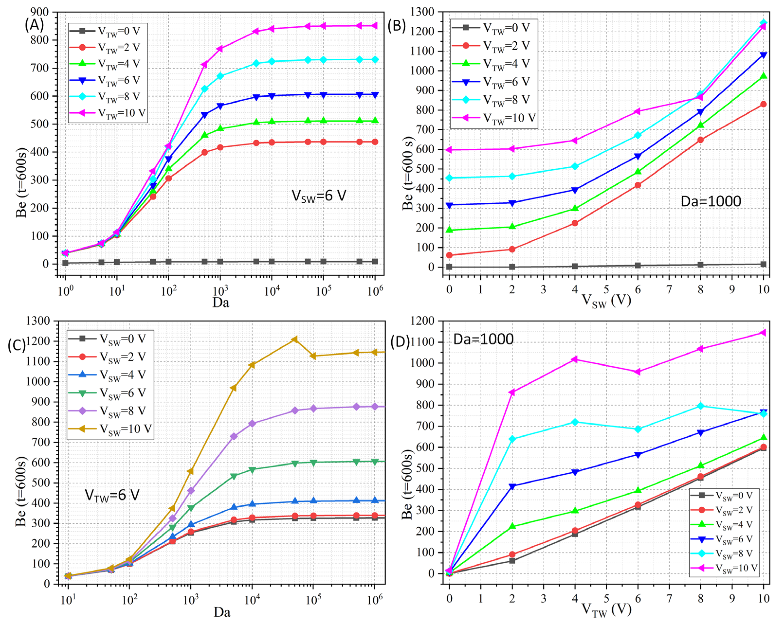
3.2.3. Cross Influence of Da Number and Voltage Amplitude on Binding Rate

After confirming the best frequency condition for MET-mediated immune reaction at the micrometer dimension, the effect of Da number on the enhancement of immunization efficiency is then investigated. The controllable adjustment of the dimensionless number Da is realized by adjusting the magnitude of the kon parameter, which helps distinguish the different antigen–antibody pairs used in practical experiments. Subsequently, we fix the Da number to 1000 and adjust the magnitude of Vsw and Vtw, respectively, to clarify the importance of dual-frequency voltage amplitude in the desired binding reaction.
Figure 8A,C shows the effect of Da number on the resulting Be at t = 600 s. As shown in Figure 8A, the Vsw is a fixed value of 6 V. When Vtw > 0, with the increase in the Da number, the Be value under different Vtw rises, and when Da value is larger than 105, the state of immune reaction saturation is attained, and Be tends to reach a stable plateau. As in Figure 8C, the Vtw is fixed at 6 V. When Da increases, the Be value under different Vsw grows and then remains stable.
Figure 8B,D shows the effect of voltage amplitude on Be. As in Figure 8B, when Vtw is a constant value of 0, there is no significant increase in Be with Vsw, because there is no horizontal TWET pump motion of the electrolyte solution. When Vtw > 0 V, then with the enhancement of Vsw, the overall Be enhancement is obvious, but there is a decline in individual data points. As shown in Figure 8D, as Vtw rises, there is a clear propensity for Be to enhance under any Vsw, but there exist some trivial individual points of decline.
Accordingly, our numerical simulations indicate that the optimal combination of SW and TW voltage signals achieves near-saturated binding efficiency at excessively large Da numbers. In addition, the enhancement of microfluidic immunoassay by MET is much more stable when both Vsw and Vtw are no more than 6 V, so we prefer to employ moderate voltage amplitudes in practical experiments.

4. Conclusions

In summary, we have demonstrated in this study the phenomenon of MET convection and its application in microfluidic immunoassay confined within a straight channel embedding a discrete array of 12 metal strips for external dual-frequency AC powering, in terms of both mathematical derivation and numerical calculation. The ideal working frequency of SWET and TWET is first obtained, on the basis of which the MET flow behavior of saline solution experiencing dual-frequency smeared structural polarization under the actuation of hybrid SW and TW voltage waves is revealed. In essence, for MET, the time-averaged synthetic electrothermal body force consists of two force components accounted for, respectively, by SWET and TWET, which are strongly coupled with each other through the action of dual-component Joule heating. The flow profile of active MET streaming commonly behaves as a delicate combination of laterally rotating SWET eddies and horizontally advancing TWET pump motion, giving rise to fully automated simultaneous electrokinetic transport and convective stirring of the incoming antigen sample within the buffer medium subjected to dual-frequency phase-shifted AC forcing. The dependence of the binding performance enhancement on the voltage amplitude and field frequency of the externally imposed SW and TW signal, as well as the reaction time due to the action of MET convection, is studied in detail. It is firmly believed that the detection sensitivity and detection limit of on-chip immunoassay are both greatly improved by implementing the twisted pump streamlines of MET fluid motion on top of an array of conducting metal strips arranged along the channel bottom surface, as long as the SW signal works in the low-frequency limit and the TW counterpart operates at the intermediate relaxation peak for moderate voltage amplitudes and a sufficiently large Da number. The numerical calculations reported herein prove that the complex electrothermal induced flow under multiple frequency AC actuation serves as a useful tool for accelerating the binding kinetics in inhomogeneous microfluidic bioassays, particularly once the immune reaction of interest is stipulated by a slow mass transfer of the target analyte.

Supplementary Materials

The following supporting information can be downloaded at: https://www.mdpi.com/article/10.3390/app15094748/s1, Video S1: Featured application movie.

Author Contributions

Q.W. derived the theory of MET and wrote the paper. S.H. wrote the paper and sought the first-order Langmuir adsorption model. S.W. conducted the numerical simulation of SWET and revised the paper. X.Z. (Xiying Zhou) conducted the numerical simulation of TWET and revised the paper. Y.S. conducted the simulation of MET and analyzed the flow behavior. X.Z. (Xiwei Zhou) conducted the simulation of the transient binding reaction at different voltage combinations. X.G. investigated the effect of signal frequency and Da number on the resulting binding kinetics. Y.T. outputted the figures and guided the research. W.L. proposed the core idea and provided the basic theory of electrokinetics and electrohydrodynamics of conducting electrolytes in microscale systems. All authors have read and agreed to the published version of the manuscript.

Funding

This research is funded by the National Natural Science Foundation of China (No. 12172064), Shaanxi Provincial Qinchuangyuan’s ‘Scientist + Engineer’ Team Construction under Grant 2022KXJ-022, the Innovation and entrepreneurship training program for college students from Chang’an University entitled “Research and development of AC Electrothermal Microfluidic Immunoassay Device”, the Key Research and Development Program of Shaanxi Province (No. 2022GY-208), and the Fundamental Research Funds for the Central Universities CHD (No. 300102322201).

Institutional Review Board Statement

Not applicable.

Informed Consent Statement

Not applicable.

Data Availability Statement

The original contributions presented in this study are included in the article/Supplementary Materials. Further inquiries can be directed to the corresponding author.

Conflicts of Interest

The authors declare no conflicts of interest.

Abbreviations

EHD, electrohydrodynamic; SWET, standing-wave electrothermal flow; TWET, traveling-wave electrothermal flow; MET, multiple-frequency electrothermal flow; DEP, dielectrophoresis; MW, Maxwell–Wagner.

References

  1. Liu, F.; KC, P.; Zhang, G.; Zhe, J. Microfluidic magnetic bead assay for cell detection. Anal. Chem. 2016, 88, 711–717. [Google Scholar] [CrossRef] [PubMed]
  2. Kim, H.; Kim, J. A microfluidic-based dynamic microarray system with single-layer pneumatic valves for immobilization and selective retrieval of single microbeads. Microfluid. Nanofluid. 2014, 16, 623–633. [Google Scholar] [CrossRef]
  3. Grilli, S.; Miccio, L.; Gennari, O.; Coppola, S.; Vespini, V.; Battista, L.; Orlando, P.; Ferraro, P. Active accumulation of very diluted biomolecules by nano-dispensing for easy detection below the femtomolar range. Nat. Commun. 2014, 5, 5314. [Google Scholar] [CrossRef] [PubMed]
  4. Zhang, Y.; Gu, H.; Xu, H. Recent progress in digital immunoassay: How to achieve ultrasensitive, multiplex and clinical accessible detection? Sens. Diagn. 2024, 3, 9–27. [Google Scholar] [CrossRef]
  5. Wang, N.; Zhang, J.; Xiao, B.; Chen, A. Microfluidic-assisted integrated nucleic acid test strips for POCT. Talanta 2024, 267, 125150. [Google Scholar] [CrossRef]
  6. Chong, S.W.; Shen, Y.; Palomba, S.; Vigolo, D. Nanofluidic Lab-On-A-Chip Systems for Biosensing in Healthcare. Small 2025, 21, 2407478. [Google Scholar] [CrossRef]
  7. Yager, P.; Edwards, T.; Fu, E.; Helton, K.; Nelson, K.; Tam, M.R.; Weigl, B.H. Microfluidic diagnostic technologies for global public health. Nature 2006, 442, 412–418. [Google Scholar] [CrossRef]
  8. Hu, G.; Gao, Y.; Li, D. Modeling micropatterned antigen–antibody binding kinetics in a microfluidic chip. Biosens. Bioelectron. 2007, 22, 1403–1409. [Google Scholar] [CrossRef]
  9. Gao, Y.; Sherman, P.M.; Sun, Y.; Li, D. Multiplexed high-throughput electrokinetically-controlled immunoassay for the detection of specific bacterial antibodies in human serum. Anal. Chim. Acta 2008, 606, 98–107. [Google Scholar] [CrossRef]
  10. Hu, G.; Li, D. Multiscale phenomena in microfluidics and nanofluidics. Chem. Eng. Sci. 2007, 62, 3443–3454. [Google Scholar] [CrossRef]
  11. Ramos, A.; Morgan, H.; Green, N.G.; Castellanos, A. Ac electrokinetics: A review of forces in microelectrode structures. J. Phys. D Appl. Phys. 1998, 31, 2338. [Google Scholar] [CrossRef]
  12. Ramos, A. Electrokinetics and Electrohydrodynamics in Microsystems; Springer Science & Business Media: Berlin/Heidelberg, Germany, 2011. [Google Scholar]
  13. Ory, S.; Ehud, Y. The Taylor-Melcher leaky dielectric model as a macroscale electrokinetic description. J. Fluid Mech. 2015, 773, 1–33. [Google Scholar]
  14. Velev, O.D.; Bhatt, K.H. On-chip micromanipulation and assembly of colloidal particles by electric fields. Soft Matter 2006, 2, 738–750. [Google Scholar] [CrossRef] [PubMed]
  15. López-Vizcaíno, R.; Navarro, V.; Yustres, Á. Two-Dimensional Modelling Approach for Electrokinetic Water Transport in Unsaturated Kaolinite. Appl. Sci. 2022, 13, 519. [Google Scholar] [CrossRef]
  16. Tripathi, D.; Narla, V.K.; Aboelkassem, Y. Electrokinetic membrane pumping flow model in a microchannel. Phys. Fluids 2020, 32, 082004. [Google Scholar] [CrossRef]
  17. Chen, L.; Lee, S.; Choo, J.; Lee, E.K. Continuous dynamic flow micropumps for microfluid manipulation. J. Micromech. Microeng. 2007, 18, 013001. [Google Scholar] [CrossRef]
  18. González, A.; Ramos, A.; Green, N.G.; Castellanos, A.; Morgan, H. Fluid flow induced by nonuniform ac electric fields in electrolytes on microelectrodes. II. A linear double-layer analysis. Phys. Rev. E 2000, 61, 4019. [Google Scholar] [CrossRef]
  19. Liu, W.; Tao, Y.; Chen, Y.; Ge, Z.; Chen, J.; Li, Y. Developing an Active Microfluidic Pump and Mixer Driven by AC Field-Effect-Mediated Induced-Charge Electro-Osmosis of Metal–Dielectric Janus Micropillars: Physical Perspective and Simulation Analysis. Appl. Sci. 2023, 13, 8253. [Google Scholar] [CrossRef]
  20. Salari, A.; Navi, M.; Dalton, C. A novel alternating current multiple array electrothermal micropump for lab-on-a-chip applications. Biomicrofluidics 2015, 9, 014113. [Google Scholar] [CrossRef]
  21. Liu, W.; Ren, Y.; Shao, J.; Jiang, H.; Ding, Y. A theoretical and numerical investigation of travelling wave induction microfluidic pumping in a temperature gradient. J. Phys. D Appl. Phys. 2014, 47, 075501. [Google Scholar] [CrossRef]
  22. Gunda, N.S.K.; Bhattacharjee, S.; Mitra, S.K. Study on the use of dielectrophoresis and electrothermal forces to produce on-chip micromixers and microconcentrators. Biomicrofluidics 2012, 6, 034118. [Google Scholar]
  23. Melcher, J.R.; Firebaugh, M.S. Traveling-Wave Bulk Electroconvection Induced across a Temperature Gradient. Phys. Fluids 1967, 10, 1178–1185. [Google Scholar] [CrossRef]
  24. Perch-Nielsen, I.R.; Green, N.G.; Wolff, A. Numerical simulation of travelling wave induced electrothermal fluid flow. J. Phys. D Appl. Phys. 2004, 37, 2323. [Google Scholar] [CrossRef]
  25. Lian, M.; Islam, N.; Wu, J. AC electrothermal manipulation of conductive fluids and particles for lab-chip applications. IET Nanobiotechnol. 2007, 1, 36–43. [Google Scholar] [CrossRef]
  26. González, A.; Ramos, A.; Morgan, H.; Green, N.G.; Castellanos, A. Electrothermal flows generated by alternating and rotating electric fields in microsystems. J. Fluid Mech. 2006, 564, 415–433. [Google Scholar] [CrossRef]
  27. Park, S.; Koklu, M.; BeskoK, A. Particle trapping in high-conductivity media with electrothermally enhanced negative dielectrophoresis. Anal. Chem. 2009, 81, 2303–2310. [Google Scholar] [CrossRef]
  28. Liu, W.; Ren, Y.; Tao, Y.; Zhou, Z.; Wu, Q.; Xue, R.; Yao, B. Multiple frequency electrothermal induced flow: Theory and microfluidic applications. J. Phys. D Appl. Phys. 2020, 53, 175304. [Google Scholar] [CrossRef]
  29. Iverson, B.D.; Cremaschi, L.; Garimella, S.V. Effects of discrete-electrode configuration on traveling-wave electrohydrodynamic pumping. Microfluid. Nanofluid. 2009, 6, 221–230. [Google Scholar] [CrossRef]
  30. Gimsa, J.; Stubbe, M.; Gimsa, U. A short tutorial contribution to impedance and AC-electrokinetic characterization and manipulation of cells and media: Are electric methods more versatile than acoustic and laser methods? J. Electr. Bioimpedance 2014, 5, 74–91. [Google Scholar] [CrossRef]
  31. Castellanos, A.; Ramos, A.; Gonzalez, A.; Green, N.G.; Morgan, H. Electrohydrodynamics and dielectrophoresis in microsystems: Scaling laws. J. Phys. D Appl. Phys. 2003, 36, 2584. [Google Scholar] [CrossRef]
  32. Green, N.G.; Ramos, A.; Gonzalez, A.; Castellanos, A.; Morgan, H. Electrothermally induced fluid flow on microelectrodes. J. Electrost. 2001, 53, 71–87. [Google Scholar] [CrossRef]
  33. Green, N.G.; Ramos, A.; González, A.; Castellanos, A.; Morgan, H. Electric field induced fluid flow on microelectrodes: The effect of illumination. J. Phys. D Appl. Phys. 2000, 33, L13. [Google Scholar] [CrossRef]
Figure 1. A schematic diagram of enhanced binding kinetics between free antigen and fixed antibody probe in microfluidic immunoassay by the phenomenon of multiple-frequency electrothermal flow (MET), which are driven by hybrid SW and TW voltage signals of distinct field frequencies and phase transition features imposed along a discrete metal strip array deposited on the bottom surface of a straight microchannel. (A) The slow diffusion motion of incoming antigen leads to almost no binding reaction on the functionalized surfaces of the sixth electrode strip. (B) On application of the desired dual-frequency phase-shifted AC signal to the integrated linear electrode track, the interaction of a thermal-dependent dielectric gradient from Joule heating with the imposed composite AC forcing induces the twisted streamlines of MET in inhomogeneous electrolyte solution, leading to simultaneous horizontal pumping and lateral stirring of incoming analyte and therefore an enhanced immunoassay on the functionalized surface of sixth electrode strip.
Applsci 15 04748 g001
Figure 2. Numerical analysis of SWET flow field in a straight PDMS microchannel embedding a three-period four-phase discrete microelectrode array situated on a silicon substrate, with a given SW voltage amplitude VSW = 6 V. (A) A surface plot of zeroth-order electrostatic potential and an arrow plot of zeroth-order electric field vector independent of the SW field frequency. (B) An arrow and surface plot of the time-averaged temperature field caused by Joule medium heating. (CE) A streamline and surface plot of electrothermal flow field due to SWET forcing at distinct signal frequencies, (C) f = 100 kHz in the low frequency limit, (D) f = 11 fMW = 77.83 MHz at the critical frequency point for flow reversal, (E) f = 10 GHz in the high frequency range. (F) Frequency-dependent electrothermal flow velocity driven by SW voltage. (G) Frequency-dependent vorticity magnitude of SWET fluid motion.
Applsci 15 04748 g002
Figure 3. Simulation analysis of various field variables in a TWET pump device with the bottom electrode array subjected to a four-phase TW signal of a given voltage amplitude VTW = 6 V. (A,B) A surface plot of the zeroth-order electrostatic potential and an arrow plot of the zeroth-order electric field for real (A) and imaginary (B) parts of the TW field with a spatially varying phase independent of the applied TW field frequency. (C) Time-averaged temperature field from Joule medium heating of the applied TW electric field. (DI) A streamline and surface plot of electrothermal flow field due to TWET forcing at distinct TW frequencies, (D) f = 1 kHz, (E) f = 1 MHz, (F) f = 10 MHz, (G) f = 22.47 MHz, (H) f = 1 GHz, and (I) f = 10 GHz.
Applsci 15 04748 g003
Figure 4. Quantitative characterization of TWET flow field as a function of the imposed TW field frequency. (A) fTW-dependent total flow velocity and its horizontal component; (B) fTW-dependent vorticity magnitude.
Applsci 15 04748 g004
Figure 5. Simulation analysis of MET fluid motion driven by a hybrid SW/TW voltage signal at the ideal frequency combination in a straight microchannel. (AC) A surface and streamline plot of the synthetic MET flow field under varying voltage amplitudes of SW and TW components, (A) at Asw = 2 V and Atw = 6 V, (B) at Asw = 6 V and Atw = 6 V, (C) at Asw = 12 V and Atw = 6 V. (D) Effect of Asw on maximum temperature elevation. (E) Effect of Atw on maximum temperature elevation. (F) Effect of Asw on electrothermal pump velocity. (G) Effect of Atw on electrothermal pump velocity. (H) Effect of Asw on electrothermal flow vorticity. (I) Effect of Atw on electrothermal flow vorticity.
Applsci 15 04748 g005
Figure 6. Simulation analysis of improvement of time-dependent immune reaction kinetics by active MET convection. (AD) A surface plot of the concentration field of incoming antigen and a streamline plot of the MET flow field under different Vsw and Vtw at the ideal frequency combination, (A) at Vsw = 0 V and Vtw = 0 V, (B) at Vsw = 6 V and Vtw = 0 V, (C) at Vsw = 0 V and Vtw = 6 V, (D) at Vsw = 6 V and Vtw = 6 V. (E) Transient evolution of the surface averaged BRT−1 on the sixth metal strip for four different combinations of SW and TW voltage amplitudes.
Applsci 15 04748 g006
Figure 7. Influence of the imposed AC signal frequency on the index of Be at t = 600 s with respect to the zero voltage condition. (A) The SW field frequency. (B) The TW field frequency.
Applsci 15 04748 g007
Figure 8. Influence of Da number and imposed voltage amplitude on MET-mediated microfluidic immunoassay. (A) Da-dependent Be for varying Atw at fixed Asw = 6 V. (B) Asw-dependent Be for varying Atw under Da = 1000. (C) Da-dependent Be for varying Asw at fixed Atw = 6 V. (D) Atw-dependent Be for varying Asw under Da = 1000.
Applsci 15 04748 g008
Disclaimer/Publisher’s Note: The statements, opinions and data contained in all publications are solely those of the individual author(s) and contributor(s) and not of MDPI and/or the editor(s). MDPI and/or the editor(s) disclaim responsibility for any injury to people or property resulting from any ideas, methods, instructions or products referred to in the content.

