Article

A Novel Approach to Wearable Image Recognition Systems to Aid Visually Impaired People

School of Instrument and Electronics, North University of China, Tai Yuan 030051, China
*
Authors to whom correspondence should be addressed.
Appl. Sci. 2019, 9(16), 3350; https://doi.org/10.3390/app9163350
Submission received: 21 July 2019 / Revised: 7 August 2019 / Accepted: 13 August 2019 / Published: 15 August 2019

Abstract

:
Action and identification problems are the challenges that visually impaired people often encounter in their lives. The high price of existing commercial intelligent auxiliary equipment has placed enormous economic pressure on most visually impaired people in developing countries. In order to solve this problem, this paper proposes a smart wearable system that performs image recognition. The system adopts the method of cloud and local cooperative processing. The cloud server mainly performs image processing, while the local unit only uploads images and feedback results. Therefore, the processor of the system does not need to use expensive high-performance hardware, and the cost is greatly reduced. Moreover, the algorithm running on the cloud server can also guarantee the speed and accuracy of recognition. In addition, we have changed the traditional video continuous scanning strategy to a mechanism for capturing points of interest, reducing power consumption. The attitude correction mechanism based on error codes of the system can effectively help the visually impaired to cope with the common living scenes, and the multiple priority feedbacks and arbitration mechanism will ensure real-time feedback of the system. The proposed smart wearable device has been tested in the actual scene, which proves to be helpful to the visually impaired people. It helps them find the right people and objects and read text.

1. Introduction

Visual impairment is a common health problem in different age groups. According to the World Health Organization (WHO) Fact Sheet of 2018, 253 million people [1] in the world are estimated to be visually impaired (VI), among which 36 million are blind and 217 million suffer from moderate to severe visual impairment. Action and cognition are the two major challenges that most visually impaired people (VIP) have in their daily lives. The corresponding solutions are navigation and image recognition. In short, if the navigation and image recognition technology can be integrated into a wearable device [2], it can greatly alleviate the current difficulties of visually impaired people.
Most of the assistive systems for the visually impaired collect visual information through various sensors, and then convert to auditory or tactile information [3,4,5]. However, the research of the assistive system is more oriented towards navigation, which is mainly to help the users solve the problem where they are and where they would go.
For instance, Pissaloux et al. [4] proposed a TactiPad device in the shape of a cube with an edge length of 8 cm weighting only 200 g. The TactiPad is mainly used for obstacle detection and a tactile gist display. Its surface can be manually explored by unconstrained hand movement. Patil, Kailas et al. have proposed a NavGuide system [6] that contains six ultrasonic sensors to detect obstacles in different directions. The system also helps the visually impaired to turn left, right, front and avoid wet floors. Yi Y et al. [7] designed a blind-guide crutch based on multiple sensors, which uses ultrasonic sensors to avoid obstacles and sends out alarm information in the form of vibration and voice. External GPS receiver [8,9] can also be used to improve the locating accuracy, But, this system can only be applied outdoors.
In addition to an ultrasonic sensor [10], RFID (Radio Frequency Identification) sensor [11,12], RGB-D camera [13] and Kinect depth camera [14] are also available as sources of visual information. But RFID systems are expensive and require indoor installation in advance, so are not adaptable to unfamiliar environments. Images captured by RGB-D cameras and Kinect cameras are converted into deep images, which consume a lot of computing resources during processing. It is improper for low-power devices. Therefore, this paper uses an ultrasonic sensor as the main obstacle avoidance sensor.
However, wearable devices that do not support object recognition are difficult to meet the daily needs of the visually impaired. They cannot know the object information of the target in front (whether it is a person or a thing, and what is the specific name). In view of this, researchers have shifted the focus of auxiliary equipment to object recognition.
As early as 2005, Krishna et al. [15] developed a pair of glasses for real-time facial recognition. They selected principal component analysis (PCA) algorithm for face recognition, with high accuracy under different facial posture and illumination angles. However, its processor is still an external small computer, so the whole system is not a perfect wearable device.
Dakopoulos D et al. [16] proposed a smart white cane that can be used for facial and expression detection. The algorithm is based on a commercial solution FaceSDK to match images to a user-built database and provide real-time audio feedback. However, the cane does not consider low power consumption.
Utsumi, Yuzuko et al. [17] designed a wearable facial recognition device, which consists of a camera, a head mounted display (HMD) and a computer. The system detects faces by using the Adaboost algorithm proposed by Viola. However, it can only detect and track a human face, so it is useless when the user meets more than two people. In addition, the use of desktop PC reduces the mobility of the device.
Most image recognition systems typically require high-performance hardware. However, a group of researchers [18] present that it is technically possible to develop a simple real-time face recognition system in a wearable device with low processing power. And they designed the Samsung Galaxy Gear, a smartwatch device that can recognize and register faces. But the problem is that in the face detection process, the user and the camera must be still for a few seconds before the next recognition process, which undoubtedly brings inconvenience to the user. Moreover, in the system test, the identification accuracy was only 83.64%.
In another study [19], the author developed a head-mounted wearable device equipped with a stereo camera, which can provide navigation service and object recognition for the blind. The system sends the video sequence collected by the camera to the cloud server through the smartphone for path planning and object recognition. However, the depth information required for the simultaneous localization and mapping (SLAM) algorithm is usually large, and it takes some time to transmit to the cloud platform, so the real-time performance will be affected. Furthermore, the device relies on smartphone support, so the controller itself cannot complete the upload service.
Recently, some researchers have proposed a Kinect-based wearable face recognition system [20], which uses a Microsoft Kinect sensor to collect facial information and perform face detection. The system can generate a sound associated with the identified person, virtualizes at his or her estimated 3-D location, making users feel that the source of sound is the location of the target. This approach is superior to the traditional face detection method but does not support object and text recognition.
With the development of artificial intelligence technology, there have been some commercialized products. The emerging smart devices such as OrCam myeye2 [21] and eSight [22], combined with image recognition technology, can help visually impaired people identify faces, texts and products, but they do not support visual path navigation.
Oxsight [23] captures the shape and distance of objects in the surrounding environment through a 3D camera, enhances the objects by highlighting, and outputs them to the mini screen of glasses. However, Oxsight can only be seen by some people with mild vision impairment, so it is hopeless for the blind.
Additionally, these commercial devices are very expensive. OrCam MyEye2 is worth $4491.9 and eSight costs $5950. However, according to the survey, about 90% of visually impaired people come from developing countries. The price will make them unaffordable. OrCam MyEye2 is also powered by a mobile power source, which undermines the portability of the wearable device. The battery life of eSight is only 2 h.
This paper aims to develop a low-cost and effective wearable smart glass, which can help users find the right people, identify common objects in life, and read paper texts. The main contribution of this paper is to propose a low-cost solution for cloud image recognition and local human-computer interaction. This method can overcome the disadvantages of expensive smart devices such as OrCam Myeye2 and ensure the accuracy and reliability of identification while ensuring low-cost and low power consumption. The entire system is deployed on a pair of lightweight and wearable glasses, to provide sound feedback and navigation for visually impaired people. The performance comparison between the system and other auxiliary equipment is shown in Table 1.
The rest of this article is organized as follows: Section 2 presents the hardware configuration of the smart device and overall system architecture. Section 3 describes the core algorithm and mathematical model of the system. Section 4 shows some test results and proves the effectiveness of the intelligent system. Finally, some conclusions are drawn in Section 5.

2. Proposed Architecture

2.1. System Overview

Our proposed cloud-based recognition solution is shown in Figure 1 below.
The proposed system (as shown in Figure 1) is a wearable device based on the cloud server for image recognition. Its sensors include a micro camera, ultrasonic sensor, and infrared sensor. The system uses the Raspberry Pi as the local processor, connecting to the cloud server via Wi-Fi or 4G network. It takes advantage of the cloud server’s powerful parallel computing power and huge storage capacity. All visual and voice processing algorithms that consume more CPU (Central Processing Unit) computing resources run in the cloud. Like the remote human brain, the cloud platform can efficiently process target information and feed the results back to the user.
Specifically, after wearing the smart glasses, the users have access to scan the points of interest. Considering the safety of visually impaired people, this program will be running until it shuts down. Scanning points of interest adopts the fusion recognition scheme of ultrasonic sensor and infrared sensor. When the infrared sensor detects someone in front of the user, there will be a ringtone prompt. The user can touch the button to start the recognition process, and the camera will capture the front image. The server will extract and identify the faces, objects and text information that may be contained in the images uploaded by the client. The server’s recognition result will be transmitted to the client and then converted to voice feedback to the user through TTS (Text To Speech) technology.

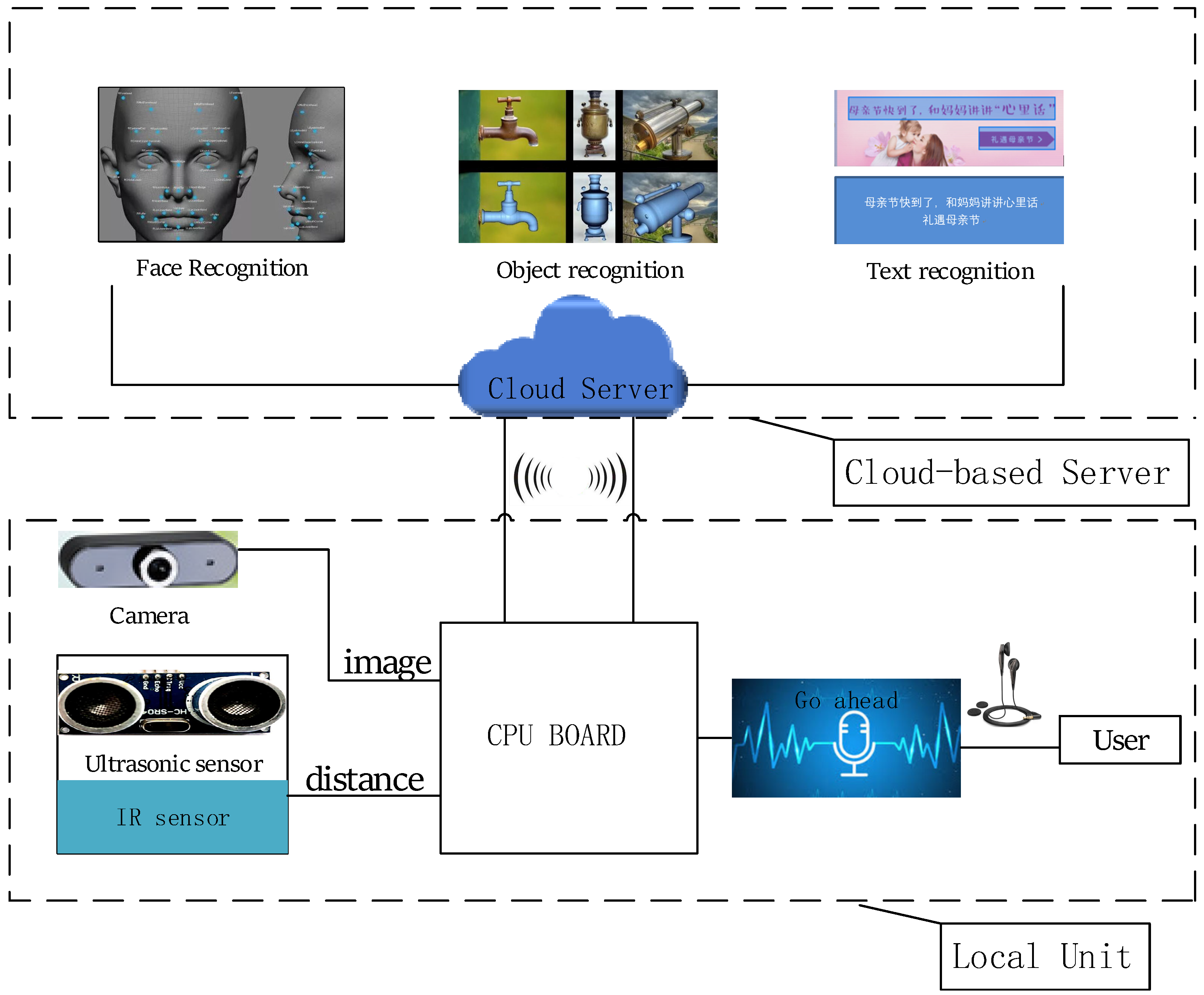
2.2. System Architecture

Elements in the system:
  • Cloud-based Server: This unit is a cloud computing platform, integrated with intelligent algorithms such as face recognition, object recognition, optical character recognition (OCR) text recognition. The server of the system uses the Baidu Cloud Server. Running the image recognition algorithm on small embedded devices brings on excessive resource usage and overlong processing time. But for a cloud server with very high hardware configurations, these algorithms can be run in parallel at high speed while ensuring accuracy and speed. It can accept processing requests from many clients at the same time, and then return the recognition results to the client in a short time, as shown in Figure 2.
  • Local Unit: it includes the control unit and the input/output unit. The structure and function of the local unit are shown in Figure 3.
    (a)
    Control unit: This unit is the brain of the whole system, which is responsible for receiving and processing visual information collected by the sensors, uploading images and analyzing the results of the server feedback. Compared to smart glasses of OrCam Myeye2, this solution has lower capability requirements for the CPU. Because the complex image recognition algorithms are run on the server instead of the local unit.
    (b)
    Input/output unit: It includes a micro camera, ultrasonic sensor, infrared sensor and headphone. The camera is the most important input part of the wearable device, serving as the “eye” of the user, which can capture the information of the surrounding environment. The ultrasonic sensor is used to measure the distance from the user to the front obstacle. Infrared sensor is mainly used to help users identify whether there is a person in front of them. It is an important input source of the multi-sensor fusion algorithm. In the choice of earphones, two options are provided: single-in-ear headphones, or Bluetooth-enabled bone conduction headphones (especially for hearing impaired people).
  • Network unit: the most important problem of online identification is the networking problem. Visually impaired people cannot configure the network, so it is necessary to maintain a good Internet connection. The system supports WIFI and 4G mobile communication. Because the stability of outdoor WIFI is too poor, 4G communication Internet has become an alternative to outdoor networking.

2.3. Physical Model

Figure 4 shows a three-dimensional model diagram of the device and a description of each part. It can be worn on the head like glasses, which is the general form of user operation. At the same time, since the controller and power supply of the device are modular in design, it can be disassembled. The user can hold the controller and power it with mobile power. Figure 5 shows the final form of the device.

3. Model and Algorithm

3.1. Image Recognition Module

In the image recognition algorithm, in addition to secondary development based on the OPENCV library, there is also the use of deep learning to complete face and object recognition. However, the hardware requirements of these algorithms are too high, which is inconsistent with our low-cost design requirements.
Therefore, we abandon the local identification scheme. In the selection of online recognition algorithms, Aliyun and Baidu Cloud and Tencent Cloud have their own recognition algorithms, but considering the openness and accuracy of Baidu AI, Baidu cloud server is finally chosen as the processing module for image recognition. Baidu AI server provides high-precision recognition of faces, objects and text. Therefore, when the camera captures the front image, the controller encodes the image and uploads it to the Baidu cloud server for processing.
With its high-performance server, the system proposed in this paper can balance the two core issues of real-time and accuracy. Moreover, we can focus more on the human-computer interaction between the visually impaired and the device.

3.2. Point of Interest Capture Algorithm Based on Multi-Sensor

The smart devices proposed in [19] and [23] obtain results by continuously scanning spatial information, which can bring more complete scene information and experience to users, but it will also bring a series of negative effects. First, continuous scanning requires hardware devices with extremely high processing power to ensure real-time performance.
Secondly, when there are many objects and people in the scene, even if the recognition speed is fast, the speed of the speech feedback to the user cannot keep up, because the pace of speech usually needs to be uniform to make people understand. Finally, continuous scanning can also lead to increased power consumption and impact on usage time.
Therefore, in this paper, an algorithm is designed to obtain the “point of interest” for recognition. Ultrasonic sensors and IR sensors are used to identify “points of interest” (usually people, larger objects, etc.) and then let the user select whether to identify through a touch button.
The calculation formula of ultrasonic ranging is shown in Equation (1):
S = 1 2 c × t
where S is the measured distance, c is the ultrasonic propagation speed, and t is the transit time.
The speed of sound in an ideal gas is shown in Equation (2).
c = v R T μ , v = 1.40 , R = 8.314   kg / ( mol K ) , T , μ = 2.8 × 10 3   kg / mol
After substituting the parameters, the approximate formula for the speed of sound is shown in Equation (3).
c = 331.5 + 0.6 t
where t is centigrade, t = T 273.5 .
If the ultrasonic sensor detects an obstacle within the detection range, the infrared sensing sensor detects whether the target contains the human body. This situation can be denoted by X. If the human body is detected, a prompt tone is immediately sent back to the user. The user can choose whether to start the identification by himself or not, and the status is denoted by P. It is mainly for the visually impaired to quickly understand the situation of the surrounding people, such as finding friends at the party and looking for family members indoors. X and P as two state functions can be expressed as Equations (4) and (5).
X = { 1 , i f | d | | d 0 | & | r | | r 0 | 0 , i f   others
where d represents the distance measured by the ultrasonic sensor, d 0 ( = 100   cm ) represents the set maximum distance of detection, r represents the distance detected by the infrared sensor, and r 0 ( = 100   cm ) represents the maximum detection range.
P = { 1 , i f   u s e r   p r e s s   t h e   b u t t o n 0 , i f   o t h e r s
Detailed execution steps are shown in Figure 6. The recognition result will include the number of people in the scene, personnel information (name, expression), the name of the object contained in the scene and the text information. The feedback mechanism will be introduced in the next section. Figure 6 shows the detailed algorithm flow chart of the scheme.

3.3. Multithreaded Processing Algorithm

Parallel processing algorithms [25] are often used in systems with real-time requirements. In order to improve the real-time performance of the device, this paper adopts a multi-thread processing scheme. It divides face recognition, calculation of the number of people, object recognition and text recognition into four threads M i ( i = 1 , 2 , 3 , 4 ) for processing. This algorithm is superior to the sequential implementation of four identification schemes. Through multi-thread processing, the thread that gets the fastest result does not directly feedback. Instead, it temporarily stores the result and finally determines the final output order through a multi-layer priority feedback mechanism (described in Section 3.5). We use function F ( α , M i ) to assign the priority of the thread, which is shown as Equation (6).
F ( α , M i ) = { 0 , P r o g r a m   i n i t i a l i z a t i o n α + 1 , i f   T h r e a d   M i   i s   e x e c u t e d   c o r r e c t l y ( α + 1 ) , i f   T h r e a d   M i   i s   e x e c u t e d   i n c o r r e c t l y
where α represents the weight of the priority, and its initial value is 0. The smaller the absolute value of F ( α , M i ) , the higher the priority of this thread. For example, when the user captures a photo of a person holding a cup of water, the face is partially obscured by the cup. If the water cup is first recognized, the object recognition priority f1 = 1; while the face is occluded, an error message is presented, and the priority of the face recognition is f2 = −2. Because f1 > f2, the user will first hear the feedback of the “cup”.
For the scheme that sequentially performs these four identification functions, we use T a to represent the main computation time cost of the program. t i represents the time required for the thread M i ( i = 1 , 2 , 3 , 4 ) to run separately, and t s i denotes the time required for each thread’s results to be converted to speech, and their relationship is expressed as Equation (7).
T a = i = 1 t i + i = 1 t s i
However, through the multi-threaded processing algorithm of this paper, the main computational cost of the program will change to T b , which is shown as Equation (8).
  T b = max { t 1 , t 2 , t 3 , t 4 } + i = 1 t s i < T a
For the user, the total time he takes from pressing the recognition button to listening to the full voice message is T u , which is shown as Equation (9).
T u = max { t 1 , t 2 , t 3 , t 4 } + i = 1 t s i + i = 1 t v i
where t v i represents the time required for each voice result to be played.

3.4. Posture Correction Mechanism Based on Error Codes

The infrared sensor can detect a certain area in the front, but the user does not know the specific location, which may lead to an incomplete face being captured by the camera. In this paper, the algorithm of correction mechanism based on error code is used to make up for this deficiency.
In the process of recognition, the error code occurs because the program is not working properly. The reason for the error code is mainly because the picture quality is unqualified, such as the light is too strong or too dark, the picture is too blurred, and the shooting target is incomplete. Visually impaired people are not aware of these situations, so these error codes just provide them with information. For example, if the error code is 223124, that is, the degree of occlusion of the left face is too high. The user will receive the audio instruction “The left face is occluded, please move to the left”, and then make corresponding movement adjustment. Table 2 lists some of the voice prompts indicated by the error code.

3.5. Feedback and Arbitration Mechanisms Based on Multiple Priority

Most of the information obtained by the visually impaired comes from auditory cues, so all the recognition results must be converted to audio by TTS technology, and the conversion time will also affect the real-time performance. At the same time, the audio the user hears should be played at a constant speed, so the first information to be played must be the most important information. Therefore, for the obstacle avoidance process, it has the highest requirements for real-time performance, so the system uses vibration and ringtone feedback. In the aspect of image recognition, different identification information is divided into multiple priorities according to function F ( α , M i ) . Users will get higher priority information first. The returned information is shown in Table 3.

4. Evaluation

This section will mainly test the accuracy and real-time performance of the system as well as its advantages compared with traditional devices. In Section 4.1, we describe the preparation of the dataset; in Section 4.2, we used the dataset to complete the test on the accuracy of face recognition and object recognition and select a reasonable threshold. We also selected different scenes to complete the function of crowd counting. In Section 4.3, we mainly test the advantages of the algorithm that does not rely on hardware, which proves the feasibility of the low-cost scheme. Meanwhile, the real-time analysis of the device is also obtained through the test results. In Section 4.4, we invited visually impaired people to conduct user experience tests and designed a questionnaire to get their feelings and suggestions after using this device.

4.1. Data Set Preparation

In 2015, Baidu AI’s image recognition algorithm won the first place with an accuracy of 99.7% in the Labeled Faces in the Wild (LFW) test. However, under the hardware conditions of this device, it is still necessary to retest its accuracy. In addition, it is difficult for visually impaired people to always take high-quality pictures, so this device cannot blindly pursue high accuracy, and it is necessary to select a reasonable threshold as a criterion for judging whether the recognition is successful.
Two currently published image recognition datasets LFW (Labeled Faces in the Wild) [26] and PASCAL VOC (Visual Object Classes) [27] were used. LFW is a database for face recognition research that contains 13,000 face images. Each face has been labeled with the name of the person pictured. 1680 of the people pictured have two or more distinct photos in the data set. In this test, LFW will be used for the test of face recognition. And advantage algorithms [28,29,30,31,32] can be employed in data processing in future work.
Our goal is not just to test accuracy at the algorithm level, but also to consider the hardware limitations of wearable devices and the needs of real-life users. According to the real life of visually impaired people, they often meet friends and relatives, so the number is not very large. Therefore, we define the number of faces they often see as 100. We have prepared three training sets and three test sets. Each training set contains 100 face images randomly selected from the LFW. Each test set contains 10 strange faces and 90 faces in the training set (but under other postures and expressions, not the original picture). Figure 7 shows some sample face of the test set.
PASCAL VOC2007 is mainly used for the test of object recognition. It contains a total of 9963 images, all of which are shot in real scenes, including people, birds, bicycles, buses, cars, bottles, chairs, dining tables, plants and other 20 common objects in daily life. We have prepared two test sets, each of which will randomly select 300 images from VOC2007. Figure 8 shows some sample picture of the test set.

4.2. Accuracy Test

4.2.1. Face Recognition in Simulation

In the experiment, we first registered the training data set into the face database. Ten unregistered faces were mixed into each test set, and the remaining 90 were all registered faces. Because faces have different similarity, we set a threshold to determine whether it is the same person. If the similarity is greater than the threshold, it is considered the same person. In this experiment, we set five possible values as thresholds for identifying test sets, and then select the most appropriate threshold according to the experimental results. The results are shown in Table 4. A total of 15 experiments were conducted, and the recognition results were recorded. TPR (true positive rate), FNR (false positive rate), FDR (false positive rate) and TNR (true negative rate) were obtained, and the results are shown as Figure 9.
It can be found that the higher the threshold we set, the smaller the value of TPR, and the larger the value of FNR, indicating that the probability that the same person is judged to be false is greater. However, in complex environments such as people’s facial expressions or different lighting and shooting angles, the higher threshold cannot be unilaterally pursued. According to the performance of the system under the five thresholds, it is reasonable to set the threshold to 80. Because in our device, the system has a feedback mechanism based on error codes. For faces with blurred or too strong light, there will be prompt feedback, and the corrected picture will be clearer than the face picture in LFW, so the recognition accuracy will be improved.

4.2.2. Object Recognition in Simulation

In the test, images of the two test sets selected from the VOC 2007 are identified one by one, and the recognition results are compared with the correct classification results. The recognition accuracy of the two groups of experiments was 88% and 90%. The main reason for the recognition error is that the picture light in the VOC is too dark or the scene contains too many people or objects.
The partial recognition results are shown as Figure 10.

4.2.3. Crowd Counting in Simulation

In the experiment of crowd counting, the street with strong light, the group discussion on the indoor table and the underground passage with dark light were selected as the test scene. It can be found that the recognition is very accurate. On the other hand, this function only provides the user with an overall awareness, and the accurate result still depends on face recognition, so it allows a certain range of errors to exist. The recognition results in the three scenarios are shown in Figure 11.

4.3. Contrast Test

In order to test that this algorithm is not particularly dependent on hardware performance, we run the algorithm on two processing platforms with very different performance. The test equipment selected is a PC with Ubuntu16.04, and its CPU is Intel(R) i7-7700HQ. The other is our smart device, whose CPU is Broadcom BCM2835 chip, with a CPU frequency of 1 GHz and a running memory of 512 MB. Obviously, their hardware performance difference is quite big. According to the final recognition results of the time to judge.
The specific test steps are as follows:
(1)
We have prepared a test set that stores two different face photos, two different object photos, and two different text photos. The file size of each image is the same, because the main control board will first encode the image before uploading the cloud server identification. Different file sizes will have different encoding times.
(2)
We connected the two test machines to the same router and set the IP flow control rules of the two machines as the unified priority to ensure that their network speeds are the same.
(3)
The test set is identified on two devices one by one, using Python’s datetime module to calculate the time required for the recognition process, and then repeating the test 10 times to obtain the average recognition time. The result is shown in Figure 12.

4.4. User-Experience Experiments

For user experience testing, four visually impaired people (age: 20–35) from the blind community were invited to test our system. Detailed information on each participant and experimental results are shown in Table 5. Two of the participants had only mild visual impairments, so they were asked to wear a black eye patch for testing. Before the formal experiment, participants will first learn how to use the device, they need to know the location of the button and the function of the two buttons, as well as understand the wearing method and audio feedback. Each participant has five minutes of learning and adaptation time, and they can try to identify the person or object in front of them. Figure 13 shows two ways to wear the device.

4.4.1. Face and Object Recognition

In the formal experiment, there are no other people’s voice prompts throughout the test session. The test steps are as follows:
(a)
Each participant wore the device to start from the designated starting point, then walked forward and scanned the room information by turning the head left and right. According to the prompt of the device (when the person is scanned, there will be a ringtone), participants were asked to find the general orientation of the person, then started the recognition and spoke out the recognition result aloud.
(b)
Each participant started from the front of the table, scanned left and right to get the name of the object, and then loudly said the recognition result. There are observers around to ensure the safety of the participants. The test environment includes seven objects (cup, glasses, personal computer, stool, trash bin, potted plant). The test room is shown as Figure 14.
The four participants completed the two parts of the test in turn, and the results of the experiment are recorded in Table 5. The main goal of testing was to gather information related to the following aspects: Do you have experience with other smart assistive devices? How many personal faces and objects did you identify during the experiment? What is their name?
In the face test, they confirmed that the infrared sensor combined with the ultrasonic sensor can help them quickly find the person’s position, which is very helpful in a party or other indoor activity. At the same time, they also pointed out that this way will lead to missing some face information, because there may be more than one person in one direction. Therefore, we advised that they should scan the number of people in the room at the starting point.
In the object recognition test, when they identify objects on the table, they prefer to use the hand to touch and find the object, and then use this device to identify. The results show that this method is more efficient than point-of-interpoint scanning in object recognition because they are familiar with the use of touch in their daily lives.

4.4.2. Text Recognition

Each participant takes turns to experience the reading of books. They can choose whether to use a head-mounted device or a handheld device. The method of reading the text requires training because the camera must be able to capture a complete page of text. Therefore, participants must learn to adjust the distance of the device to the text. White cardboard is used to block the other side of the book, preventing the recognition result from containing text from another page. The left thumb holds down the left border of the book and then recognizes it according to the shooting posture and distance shown in Figure 15.
In this experiment, the questions used are as follows: after training, can you take a complete text picture? Do you prefer to use a head-mounted device or a handheld device for text reading? Is the recognition time during text reading acceptable? Participants’ feedback on these issues will be discussed in the next section. It can be found that, if it is not a special font, the recognition rate is quite high enough for daily reading. The text and recognition results are shown in Figure 16.

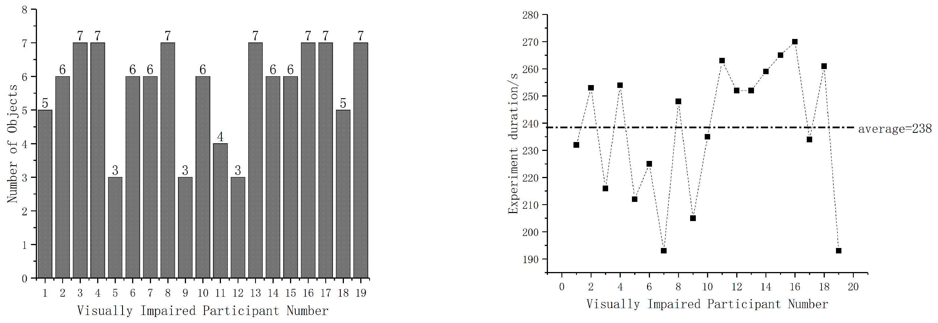
4.4.3. Second Round of Experimental Evaluation

By conducting the first round of experiments, we got good results, but the only problem was that there were too few experimental participants. Therefore, we designed a second round of experiments. We invited 30 people to fill out the questionnaire. The result is shown in Table 6. Then we chose 19 visual impairment people who are willing to experience the device to participate in the test. The 12 participants were between 20 and 40 years old, and the rest were between 40 and 60 years old.
We repeated the training process for the first round of experiments. However, face recognition and text recognition verification were not performed in this experiment, because these two functions are similar to the process of object recognition. These 19 participants repeated the first round of object recognition experiment. The results of the second round are shown in Figure 17.
In the second round of experiments, the number of participants increased, and we obtained more abundant experimental data. From the results shown in Figure 17, the device is helpful for visually impaired people to identify objects. Most people can find more than five objects, they said that using this device to “see objects” makes them very excited.
However, we have to admit that different people have different degrees of mastery of the device. For example, during the experiment, four participants between the ages of 40 and 60 said they needed more time to practice. Therefore, we believe that this difference should be taken into account in future research, and even multiple devices should be developed to be suitable for visually impaired people of different ages.

4.5. Discussion

After all participants completed the task, we conducted a post-test debrief interview with users about the experience during the testing. In addition to the issues mentioned above, the main goal of testing was to gather information related to the following aspects: Is the device easy to learn? Which type of device do you prefer to use? Is the real-time capability of the device meeting your daily needs? What is your impression of the device? Do you have any suggestions for this device? After discussions with them, the following conclusions can be highlighted:
  • The visually impaired people who participated in the experiment expressed their willingness to experience this device and felt that the modular design was cool. In addition, they think the system is easy to learn because of vibrations, ring tones, and audio information. Therefore, they only need to make a corresponding judgment according to the prompt.
  • A participant said that he preferred hand-held type device instead of wearing his head, especially when reading text. Because he only needs to control the vertical distance between the device and the book by hand, instead of moving the head. Six participants expressed their support for his views.
  • Most participants suggested that we should choose a thinner mobile power source so that the hand-held device can be easily placed in the pocket. The weight of the head-mounted device also needs to be further reduced.
  • When asked if the recognition speed can meet the daily needs, they said that the recognition time of 2–3 s is completely acceptable. Furthermore, they pay more attention to accuracy than time. They are willing to use the device at a party or at home to find their acquaintances.
  • Two participants indicated that the number of vibrations was frequent when an object was detected, which affected the wearing comfort. They suggested reducing the frequency of detecting obstacles or pausing vibrations while identifying objects.
  • All participants indicated that the price of $250 is acceptable. They have always believed that the price of smart assistive equipment is very high and cannot be afforded at all.
It is worth mentioning that during the experiment, we did not design an obstacle avoidance test. Because the ultrasonic module of the device mainly plays a role in scanning the interest points with the infrared sensor, reliable obstacle detection cannot be achieved. But we have considered three solutions. The first is to add the SLAM algorithm to achieve camera-based navigation, but it also has high requirements for hardware devices. Therefore, our future research direction is to put the online SLAM algorithm and image recognition algorithm in the cloud server for processing.
The second option is to increase the number of ultrasonic modules or other distance-measuring sensors. As Bogdan Mocanu et al. proposed [33], using a smart phone belt for obstacle detection, there are four ultrasonic modules that detect the left side of the user. Right, center left, center right. But this will increase the weight and energy consumption of our device.
The third solution is to combine our system with a white cane. Because the white cane is the most familiar obstacle avoidance device for most visually impaired people, it has the advantages of simplicity and reliability. We believe that smart assistive devices should not completely replace white canes, at least in the current transition period, because the novel smart devices are not mature enough.

5. Conclusions

This paper describes a wearable system that performs image processing based on the cloud. The system uses ultrasonic sensors and infrared human body sensors to capture points of interest in the scene, and then uses a micro-camera for specific identification. The recognition of faces, objects and texts is achieved.
In contrast to traditional programs, we have new discoveries. The hardware size and cost of traditional wearable devices are limited, new algorithms in a frontier field often have high recognition accuracy but are particularly demanding on hardware. So, these new algorithms are generally not able to run on traditional wearable devices. However, these algorithms can be run efficiently on high-performance cloud servers. Another benefit is that the system upgrade iteration of the device does not affect the user at all. That is, the user does not need to spend money to purchase a new product because of system iteration, because a lot of optimizations often only need to be deployed and modified in the cloud. This is undoubtedly an excitement for most visually impaired people.
Our results have confirmed the effectiveness of this device in image recognition, and currently it costs only $250 in terms of the price of the device. However, if the research results are to be converted into commercial products, the equipment will need to upgrade the hardware process while using better quality sensors. The current shortcoming of the program is that the path planning function has not been added yet. In the future, our work is to integrate online visual navigation into the device. With the development of the 5G era, it is no longer an issue for depth image information to be transmitted to the cloud, or for users to be helped with path planning in real time.

Author Contributions

H.C., S.C. and D.Y. conceived and designed the experiments; S.C. and C.S. performed the experiments; H.C. and D.Y. analyzed the data, and S.C. wrote the paper.

Funding

This work is supported by National Natural Science Foundation of China (No. 51705477 and No. 61603353), and Pre-Research Field Foundation of Equipment Development Department of China No. 61405170104. The research is also supported by program for the Top Young Academic Leaders of Higher Learning Institutions of Shanxi, Fund Program for the Scientific Activities of Selected Returned Overseas Professionals in Shanxi Province, Shanxi Province Science Foundation for Youths (No. 201801D221195), Young Academic Leaders of North University of China (No. QX201809), the Open Fund of State Key Laboratory of Deep Buried Target Damage No. DXMBJJ2017-15, and the Fund for Shanxi “1331 Project” Key Subjects Construction.

Conflicts of Interest

The authors declare no conflicts interest.

References

  1. Blindness and Vision Impairment. Available online: https://www.who.int/zh/news-room/fact-sheets/detail/blindness-and-visual-impairment (accessed on 1 May 2019).
  2. Jafri, R.; Ali, S.A. Exploring the Potential of Eyewear-Based Wearable Display Devices for Use by the Visually Impaired. In Proceedings of the 2014 3rd International Conference on User Science and Engineering (i-USEr), Shah Alam, Malaysia, 2–5 September 2014; pp. 119–124. [Google Scholar]
  3. Maisto, M.; Pacchierotti, C.; Chinello, F.; Salvietti, G.; De Luca, A.; Prattichizzo, D. Evaluation of Wearable Haptic Systems for the Fingers in Augmented Reality Applications. IEEE Trans. Haptics 2017, 10, 511–522. [Google Scholar] [CrossRef] [PubMed] [Green Version]
  4. Pissaloux, E.E.; Velázquez, R.; Maingreaud, F. A New Framework for Cognitive Mobility of Visually Impaired Users in Using Tactile Device. IEEE Trans. Hum.-Mach. Syst. 2017, 47, 1040–1051. [Google Scholar] [CrossRef]
  5. Andò, B.; Baglio, S.; Marletta, V.; Valastro, A. A Haptic Solution to Assist Visually Impaired in Mobility Tasks. IEEE Trans. Hum.-Mach. Syst. 2015, 45, 641–646. [Google Scholar] [CrossRef]
  6. Patil, K.; Jawadwala, Q.; Shu, F.C. Design and Construction of Electronic Aid for Visually Impaired People. IEEE Trans. Hum.-Mach. Syst. 2018, 48, 172–182. [Google Scholar] [CrossRef]
  7. Yi, Y.; Dong, L. A design of blind-guide crutch based on multi-sensors. In Proceedings of the 2015 12th International Conference on Fuzzy Systems and Knowledge Discovery (FSKD), Zhangjiajie, China, 15–17 August 2015; pp. 2288–2292. [Google Scholar]
  8. Lapyko, A.N.; Tung, L.P.; Lin, B.S.P. A Cloud-based Outdoor Assistive Navigation System for the Blind and Visually Impaired. In Proceedings of the 2014 7th IFIP Wireless and Mobile Networking Conference (WMNC), Vilamoura, Portugal, 20–22 May 2014; pp. 1–8. [Google Scholar]
  9. Shen, C.; Zhang, Y.; Tang, J.; Cao, H.; Liu, J. Dual-optimization for a MEMS-INS/GPS system during GPS outages based on the cubature Kalman filter and neural networks. Mech. Syst. Signal Process 2019. In Press. [Google Scholar]
  10. Simões, W.C.S.S.; de Lucena, V.F. Blind user wearable audio assistance for indoor navigation based on visual markers and ultrasonic obstacle detection. In Proceedings of the 2016 IEEE International Conference on Consumer Electronics (ICCE), Las Vegas, NV, USA, 9–11 January 2016; IEEE: Piscataway, NJ, USA, 2016; pp. 60–63. [Google Scholar]
  11. Sammouda, R.; Alrjoub, A. Mobile blind navigation system using RFID. In Proceedings of the Computer & Information Technology, Liverpool, UK, 26–28 October 2015; IEEE: Piscataway, NJ, USA, 2015; pp. 1–4. [Google Scholar]
  12. Yamashita, A.; Sato, K.; Sato, S.; Matsubayashi, K. Pedestrian Navigation System for Visually Impaired People Using HoloLens and RFID. In Proceedings of the 2017 Conference on Technologies and Applications of Artificial Intelligence (TAAI), Taipei, Taiwan, 1–3 December 2017. [Google Scholar]
  13. Owayjan, M.; Hayek, A.; Nassrallah, H.; Eldor, M. Smart Assistive Navigation System for Blind and Visually Impaired Individuals. In Proceedings of the International Conference on Advances in Biomedical Engineering, Beirut, Lebanon, 16–18 September 2015; IEEE: Piscataway, NJ, USA, 2015; pp. 162–165. [Google Scholar]
  14. Krishna, S.; Little, G.; Black, J.; Panchanathan, S. A wearable face recognition system for individuals with visual impairments. In Proceedings of the International ACM SIGACCESS Conference on Computers & Accessibility, Baltimore, MD, USA, 9–12 October 2005; ACM: New York, NY, USA, 2005. [Google Scholar]
  15. Astler, D.; Chau, H.; Hsu, K.; Hua, A.; Zaidi, K. Increased accessibility to nonverbal communication through facial and expression recognition technologies for blind/visually impaired subjects. In Proceedings of the International ACM SIGACCESS Conference on Computers & Accessibility, Dundee, Scotland, UK, 24–26 October 2011. [Google Scholar]
  16. Utsumi, Y.; Kato, Y.; Kai, K.; Iwamura, M.; Kise, K. Who are you? A wearable face recognition system to support human memory. In Proceedings of the Augmented Human International Conference, Stuttgart, Germany, 7–8 March 2013. [Google Scholar]
  17. Neto, L.D.; Maike, V.R.; Koch, F.L. A Wearable Face Recognition System Built into a Smartwatch and Low Vision Users. In Proceedings of the International Conference on Enterprise Information Systems, Barcelona, Spain, 27–30 April 2015; Springer International Publishing: Cham, Switzerland, 2015. [Google Scholar]
  18. Bai, J.; Liu, D.; Su, G.; Fu, Z. A Cloud and Vision-based Navigation System Used for Blind People. In Proceedings of the International Conference on Artificial Intelligence, Cambridge, UK, 12–14 December 2017. [Google Scholar]
  19. Neto, L.B.; Grijalva, F.; Maike, V.R.M.L.; Martini, L.C.; Florencio, D.; Baranauskas, M.C.C.; Rocha, A.; Goldenstein, S. A Kinect-Based Wearable Face Recognition System to Aid Visually Impaired Users. IEEE Trans. Hum.-Mach. Syst. 2017, 47, 52–64. [Google Scholar] [CrossRef]
  20. Klatzky, R.L.; Marston, J.R.; Giudice, N.A.; Golledge, R.G.; Loomis, J.M. Cognitive load of navigating without vision when guided by virtual sound versus spatial language. J Exp. Psychol. Appl. 2006, 12, 223–232. [Google Scholar] [CrossRef] [PubMed]
  21. OrCam MyEye 2. Available online: https://www.orcam.com/en/myeye2/ (accessed on 1 January 2019).
  22. An Invention that Changes Lives. Available online: https://www.esighteyewear.com/ (accessed on 2 March 2019).
  23. Widen Your Outlook. Available online: https://www.oxsight.co.uk/ (accessed on 1 March 2019).
  24. AngelEye. Available online: http://www.sohu.com/a/146918335_736159/ (accessed on 10 July 2019).
  25. Shen, C.; Yang, J.; Tang, J.; Liu, J.; Cao, H. Note: Parallel processing algorithm of temperature and noise error for micro-electro-mechanical system gyroscope based on variational mode decomposition and augmented nonlinear differentiator. Rev. Sci. Instrum. 2018, 89, 076107. [Google Scholar] [CrossRef] [PubMed]
  26. Labeled Faces in the Wild Home. Available online: http://vis-www.cs.umass.edu/lfw/index.html (accessed on 21 May 2019).
  27. The PASCAL Visual Object Classes Challenge. 2007. Available online: http://host.robots.ox.ac.uk/pascal/VOC/voc2007/ (accessed on 1 March 2019).
  28. Wang, Z.; Zhou, J.; Wang, J.; Du, W.; Wang, J.; Han, X.; He, G. A novel Fault Diagnosis Method of Gearbox Based on Maximum Kurtosis Spectral Entropy Deconvolution. IEEE Access 2019, 7, 29520–29532. [Google Scholar] [CrossRef]
  29. Wang, Z.; Du, W.; Wang, J.; Zhou, J.; Han, X.; Zhang, Z.; Huang, L. Research and Application of Improved Adaptive MOMEDA Fault Diagnosis Method. Measurement 2019, 140, 63–75. [Google Scholar] [CrossRef]
  30. Wang, Z.; He, G.; Du, W.; Zhou, J.; Han, X.; Wang, J.; He, H.; Guo, X.; Wang, J.; Kou, Y. Application of Parameter Optimized Variational Mode Decomposition Method in Fault Diagnosis of Gearbox. IEEE Access 2019, 7, 44871–44882. [Google Scholar] [CrossRef]
  31. Wang, Z.; Wang, J.; Cai, W.; Zhou, J.; Du, W.; Wang, J.; He, G.; He, H. Application of an Improved Ensemble Local Mean Decomposition Method for Gearbox Composite Fault diagnosis. Complexity 2019, 2019, 1564243. [Google Scholar] [CrossRef]
  32. Wang, Z.; Zheng, L.; Du, W. A novel method for intelligent fault diagnosis of bearing based on capsule neural network. Complexity 2019, 2019, 6943234. [Google Scholar] [CrossRef]
  33. Mocanu, B.; Tapu, R.; Zaharia, T. When Ultrasonic Sensors and Computer Vision Join Forces for Efficient Obstacle Detection and Recognition. Sensors 2016, 16, 1807. [Google Scholar] [CrossRef] [PubMed]
Figure 1. Architecture of the proposed system.
Applsci 09 03350 g001
Figure 2. Cloud server and multiple local terminals.
Applsci 09 03350 g002
Figure 3. Local unit.
Applsci 09 03350 g003
Figure 4. The 3D model of the device.
Applsci 09 03350 g004
Figure 5. The head-mounted type device (left) and hand-held type device (right).
Applsci 09 03350 g005
Figure 6. Point of interest capture algorithm based on multi-sensor.
Applsci 09 03350 g006
Figure 7. Partial sample face of the Labeled Faces in the Wild (LFW) database [26].
Applsci 09 03350 g007
Figure 8. Partial sample pictures of the LFW PASCAL VOC2007 [27].
Applsci 09 03350 g008
Figure 9. True positive rate (TPR) and true negative rate (TNR) under different thresholds.
Applsci 09 03350 g009
Figure 10. Some results of object recognition.
Applsci 09 03350 g010
Figure 11. The recognition results in the three scenarios.
Applsci 09 03350 g011
Figure 12. Recognition time of different processing platforms.
Applsci 09 03350 g012
Figure 13. One participant wears a head-mounted (left) and a hand-held (right) device.
Applsci 09 03350 g013
Figure 14. Face recognition test (left) and object recognition test (right).
Applsci 09 03350 g014
Figure 15. Correct reading of text posture.
Applsci 09 03350 g015
Figure 16. The left side of the image is the parcel, and the right side is the recognized text.
Applsci 09 03350 g016
Figure 17. Experimental results (left) and duration of the experiment (right).
Applsci 09 03350 g017
Table 1. Comparison with other equipment in performance parameters.
EquipmentOur SystemOrCam MyEye2 [21]Oxsight [23]eSight [22]AngleEye [24]
Appearance DescriptionGlassesGlassesGlasses+
Controller+
External power
Glasses+
Controller
glasses+
APP
Target userALL VIPALL VIPLow vision peopleLow vision peopleALL VIP
Image RecognitionYYNNY
Obstacle avoidanceY (defective)NNNY (Route navigation through voice)
IndependentYYYYN (needs APP)
endurance time of the batteryby buttongestureContinuous scanningContinuous scanningby button
endurance time of the battery and battery capacity5 h
(1200 mAh)
Unpublished
(320 mAh)
Unpublished
(external power)
2 h
(unpublished)
Unpublished
(external power)
Price ($)2504491.9377.2559501191.6
Table 2. Some of the voice prompts indicated by the error code.
Error CodeSound Prompt
222202picture not have face
222207match user is not found
223113face is covered
223114face is fuzzy
223115face light is not good
223116incomplete face
223125right eye is occlusion
216200empty image
282102The target is not detected
282103target recognize error
Table 3. Information returned by different threads in different situations.
Thread M i ConditionReturn Result
M 1 Human beings in the picture ( F ( α , M 1 ) > 0 )Number of the people
M 2 Image quality is unqualified ( F ( α , M 2 ) < 0 )Left/right face is occluded
Blurring pictures
The light is too strong
Registered in the face database ( F ( α , M 2 ) > 0 )name
Not added in the face database ( F ( α , M 2 ) < 0 )appearance information (age, expression, glasses)
M 3 Object ( F ( α , M 3 ) > 0 )Object name
M 4 Book or other text ( F ( α , M 4 ) > 0 )sound of the text
Table 4. The number of faces successfully recognized under different thresholds.
ThresholdTest_Face 1Test_Face 2Test_Face 3
90818488
85777986
80848185
75878588
70838290
Table 5. Personal and experimental details of each participant.
Participant 1Participant 2Participant 3Participant 4
GenderMaleFemaleMaleFemale
Age20253533
Degree of visual impairmentSlightSlightLow visionLow vision
Experience of using other aidsY
(TapTapsee-An IOS APP)
NNN
Experiment duration (min)5′5″5′20″6′25″6′42″
Explain usage before experimentYesYesYesYes
Face number3222
Object typesCup, glasses, PC, stool, trash binCup, PC, glasses, plate, stool, potted plantCup, PC, glasses, plate, trash binCup, PC, glasses, plate, stool, trash bin
Table 6. Questionnaire and final statistical results.
Age Range (Number)<20 (0)20–39 (16)40–60 (10)>60 (4)
genderMale (18)Female (12)
Do you have experience with smart assistive devices?Yes (4)No (26)
Degree of visual impairmentLow vision (9)Blind (21)
Would you like to experience our equipment?Yes (19)Maybe later (11)

