Article

Development of a Comprehensive Model for the Coulombic Efficiency and Capacity Fade of LiFePO4 Batteries under Different Aging Conditions

Department of Engineering Science and Ocean Engineering, National Taiwan University, No. 1, Sec. 4, Roosevelt Rd., Taipei 106, Taiwan
Appl. Sci. 2019, 9(21), 4572; https://doi.org/10.3390/app9214572
Submission received: 28 September 2019 / Revised: 14 October 2019 / Accepted: 23 October 2019 / Published: 28 October 2019
(This article belongs to the Special Issue Battery Management System for Future Electric Vehicles)

Abstract

:
In this paper, a comprehensive model for LiFePO4 batteries is proposed to ensure high efficiency and safe operation. The proposed model has a direct correlation between its parameters and the electrochemical principles to estimate the state of charge (SoC) and the remaining capacity of the LiFePO4 battery. This model was based on a modified Thévenin circuit, Butler–Volmer kinetics, the Arrhenius equation, Peukert’s law, and a back propagation neural network (BPNN), which can be divided into two parts. The first part can be represented by the dual exponential terms, responsive to the Coulomb efficiency; the second part can be described by the BPNN, estimating the remaining capacity. The model successfully estimates the SoC of the batteries that were tested with an error of 1.55%. The results suggest that the model is able to accurately estimate the SoC and the remaining capacity in various environments (discharging C rates and temperatures).

1. Introduction

LiFePO4 is one of the most popular cathode materials for lithium batteries with developmental potential. In recent years, it has become a research topic receiving attention from both academia and industry. The battery possesses advantages such as high coulombic efficiency [1,2], high theoretical capacity (170 mAh·g−1), low cost, and a long cycle life. It is widely employed in many energy storage commercial applications such as electric vehicles and hybrid vehicles [1,2,3,4]. However, under variable working conditions, such as different temperatures, depths of discharge, charging and discharging rates, and numbers of cycles, the aging of the battery would speed up, leading to error in estimating the battery strength. Much research has been conducted to investigate the mechanisms of battery aging [5,6,7,8,9]. However, it is still a major challenge to quantify these factors’ influence on battery performance.
Since battery aging is a process of a set of complex mutual interactions, aging will be sped up by a high charging/discharging rate, a working environment of high or low temperature and over-discharge. When the environmental temperature is higher than 45 °C, the efficiency of the anode will be influenced by surface formation and structural degeneration, which becomes a significant factor for the aging of LiFePO4 batteries. The battery life at 55 °C is 1/7 of that at 25 °C [10]. Rising temperature clearly promotes the dissociation of the electrolyte and iron ions dissolving [11], leading to the lithium ions being rapidly used up and the degradation of the anode’s structure, accelerating the aging of the LiFePO4 battery. In contrast, when the environmental temperature is below 0 °C, the rate of electrochemical reactions drops. This includes ion conduction in the electrolyte, the transmission of lithium ions through solid state electrolyte interface, charge transferral at interface, and the rate of spread of the solid-state lithium. As a result, there are losses in energy and strength [12,13,14]. The main phenomenon causing this kind of rapid capacity fading is known as lithium electroplating, occurring when a battery is always under harsh operating conditions, such as low temperature, strenuous charge, or overcharging [15,16,17]. Among the various degradation mechanisms occurring in the Li-ion batteries, lithium plating is considered as one of the most detrimental. Because the lithium plating not only catalyzes further degradation, but also affects the safety of the battery operation [18,19]. The discharging current also has a large influence on the degradation of battery performance. The work in [20] has shown from simulation results that under high discharge rate, the battery shows a poorer cycle life. Since joule heating and electrochemical reaction heat are released in the battery in charging and discharging conditions, the two exhibit a positive relationship with the current strength.
Electrode tabs are the small metallic strips that are welded onto the current collectors without active materials [21]. When the battery is charged or discharged, the current density near the electrode tabs is higher, which means the temperature of the active materials inside the battery is also higher near the electrode tabs. Uneven temperature distribution will lead to rapid aging of some of the battery’s active materials; thus, the available capacity drops. When batteries are sealed into battery packs or are under a high temperature working environment, temperature difference between areas near the electrode tabs and other parts will become even more pronounced. The main reason being a higher temperature will accelerate the rate of rapid secondary reactions of the cathode and the solid electrolyte interface (SEI) growth rate [20]. Conversely, when the batteries are connected in series and sealed into a battery pack, uneven temperature distribution will accelerate aging of active materials locally among the batteries, leading to a drop in capacity [12,20]. This will finally lead to capacity imbalance of battery units in the battery pack, causing malfunction [22].
From the above description, it can be seen that environmental temperature has a large influence on battery aging [23]. The uneven heating produced from a high rate of discharge will also lead to aging of some of the internal materials in the battery, speeding up the aging process [24]. Thus, only when these causes are considered will the batteries operate safely and efficiently.
State of charge (SoC) is defined as the available capacity and expressed as a percentage of the battery’s rated capacity. SoC estimation based on the ampere-hour method is calculated using
S o C ( t ) = S o C ( t 0 ) 1 C N ( t ) t 0 t ( η c · i ( t ) S d ) d t ,
where S o C ( t ) is the SoC at time t; S o C ( t 0 ) is the initial value; C N is the rated capacity; η c is the coulombic efficiency; S d is the self-discharge rate; and i ( t ) is the current, which is positive during the discharging process and negative during the charging process.
In Equation (1), coulombic efficiency (CE) can be used to estimate the relationship between SoC and cycle life [25,26,27]. For LiFePO4 batteries under room temperature, CE > 0.994 and the self-discharge rate is lower than 5% per month [10]. If temperature and self-discharge are not considered, the equation can be simplified by assuming η c = 1 and S d = 0 . However, temperature change strongly affects CE. When used under low temperature environments and for some high power applications such as electric vehicles, there will be safety issues. In addition, the capacity will fade as the number of cycles increase, causing considerable errors in SoC estimation.
In order to correct the measurement errors of the battery, the work in [28] proposed practical state-of-charge. This definition uses a practical operational capacity, instead of the manufacturer’s rated capacity, as the maximum amount of charge. It can be expressed as
S o C N = Q a v a i l a b l e C m a x , p ,
where C m a x , p , represents the maximum practical capacity as measured from the operating battery at the current time. C m a x , p may fade over time, due to the effect of battery aging.
During the charging process of lithium batteries, a SEI is formed, leading to loss of active lithium ions and lowering of capacity. State of health (SoH) is another important method of estimation for battery health management. It is the direct indication of the health condition of the battery system. A battery’s SoH normally ranges within 0–100%, but when it is new, SoH can be slightly larger than 100% due to product variations [29]. In this paper, to avoid confusion, the SoHN of the battery refers to the ratio of battery discharge capacity to new battery rated capacity under certain conditions. SoHN can be expressed as
S o H N = C m a x , p C N .
Battery models describe the charging and discharging behaviors of batteries and information such as calculated capacity, state of health, etc. They can be used for preventing overcharging or over discharging. SoC and SoH are both indispensable methods for battery models. The battery models are categorized into electrochemical models and equivalent circuit models [30]. Electrochemical models use equations of physical phenomena and micro-structure of materials to predict battery performance [31,32,33]. They are often used to study single specific batteries, analyze the phase changes of battery materials, study the influence from porous structure of battery electrode tabs [34], and optimize the tab porosity rate and tab thickness [35]. Simultaneously, electro-chemical models are also used in improving battery design and manufacturing. However, high computational complexity is the major disadvantage. The models also cannot be used for estimating the performance of battery packs consisting of multiple batteries in electric vehicles. On the other hand, equivalent circuit models can describe battery SoC, SoH, and impedance. Together with actually measured currents and voltages, batteries’ non-linear dynamic behaviors can be shown [36,37].
In recent years, machine learning has also been employed for calculations to analyze battery states [38]. Through a great deal of training data, the error between predicted and measured battery performance is minimized. The typical algorithm is an artificial neural network (ANN). In terms of precision, it gives stellar results. Parameters can be calibrated to enable preserving fine performance of the battery in its life cycle [39,40,41,42]. However, since machine learning is based on mathematical optimization, battery behaviors and potential physical phenomena cannot be linked together.
This research proposes a comprehensive model to describe the discharging behavior of LiFePO4 batteries. In the model, parameters of the discharging behaviors and electrochemical phenomena are intimately related.
The proposed model is based on a modified Thevenin circuit, Butler–Volmer kinetics, the Arrhenius equation, Peukert’s law, and a back-propagation neural network (BPNN). The model estimates the CE and the remaining capacity of the battery in various environments. The simplifications of the electrochemistry equations make it possible to integrate it into equivalent circuit models in order to predict the battery’s states during real operation.
The structure of the paper is as follows: Section 2 describes the experimental framework, procedures, and the experimental data. Section 3 introduces the battery models and terminology used throughout this paper. The work including battery modeling and its parameter identification are given in Section 4. A comprehensive battery model is presented to simulate the discharging behavior of the batteries. Curve fitting was employed to estimate the SoC and battery’s parameters, while the BPNN estimated the SoH. Section 5 describes that battery capacity tests were conducted to verify the accuracy and robustness of the proposed method in various environments. The SoC estimation results are shown and analyzed. Lastly, the conclusions are drawn in Section 6.

2. Experimental Setup and Procedures

The performance of lithium batteries must be consistent under load and temperature variations. Hence, coulombic efficiency and capacity fade of the battery were analyzed experimentally under various environmental conditions to provide information for electric vehicles and other devices, as well as to ensure operational stability. The method of gathering model parameters was to set up 28 LiFePO4 batteries under 7 temperature settings and 4 discharge rates during charging and discharging 400 cycles. The training and testing data for battery models was constructed from this method. The CE was developed to fit the discharging curve dependent on temperature and discharge current. The irreversible capacity fade of the battery was developed by ANN.

2.1. Experimental Process

In this research, all of the lithium-ion batteries were LYS347094S from Taiwan’s LYNO Corporation. These batteries’ working voltage and capacity are rated at 3.2 V and 10 Ah. In accordance with the data sheet from the manufacturer, the discharging rates under various temperatures of −10, 0, 10, 20, 30, 40, and 50 °C in a temperature-controlled chamber were tested (DBL45 from Taiwan Dengyng Tec Corporation). These LiFePO4 batteries were discharged under rates of 0.5, 1, 2 and 3 C by a Chroma 17020 battery test station. These batteries were cycled 400 times, within the limits recommended by the manufacturer. Information such as capacity attenuation and number of cycles of the batteriesweare computer recorded. The model was constructed in MATLAB software platform to analyze the recorded discharging curve and perform curve fitting. The experimental setup flowchart is shown in Figure 1.

2.2. Coulombic Efficiency Analysis of a Battery under Different Temperatures and Discharge C Rates

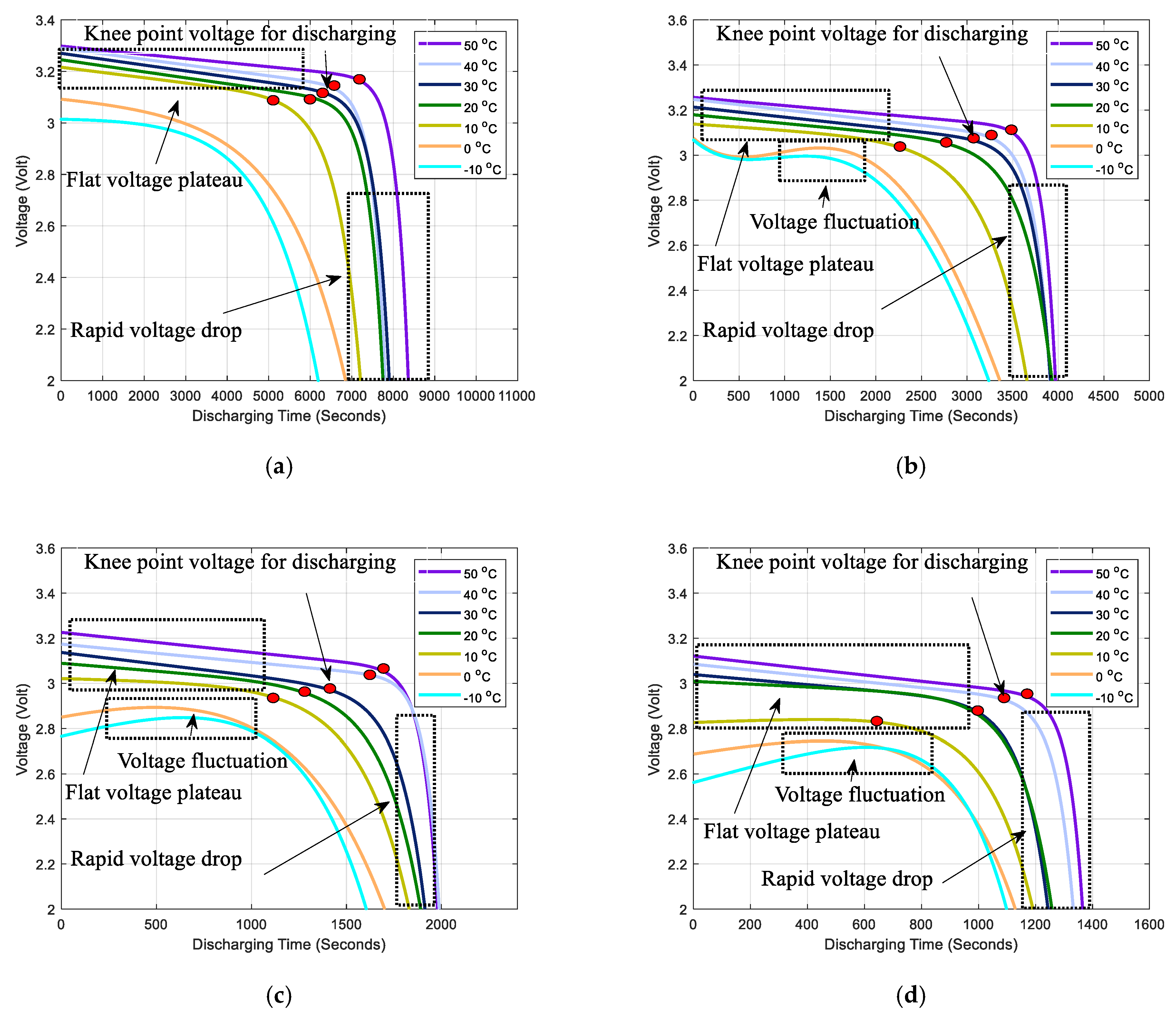
Characteristics of the discharging behaviors and voltage variation with time of LiFePO4 battery exhibit a curve with a very flat voltage plateau and a very obvious voltage drop point. When the capacity is ample, the discharging curve is very stable. Once the voltage drop point is reached, the voltage will rapidly drop suggesting that the remaining capacity will be insufficient, as shown from Figure 2a–d. From the figures, the battery voltage decreases drastically, since the curve goes through a knee point, and eventually drops to the cut-off voltage, at which the battery has been exhausted [43,44,45,46]. Accord to Faraday’s law, the capacity is equal to the integral of current over time. The voltage represents an important characteristic for ample capacity. When the capacity fades, the voltage will be rapid drop, which means that the discharge time before the knee point is significantly reduced [47,48]. The discharge curves between 10 °C and 50 °C can be seen. Before the knee point, the voltage drop is insignificant. Once the knee point is reached, the voltage would rapidly fall [49]. However, the curves of −10 and 0 °C are monotonic. Their knee points are also not obvious. As the discharging rate increases, voltage fluctuation is observable. At the same time, the discharging time of the battery under a low temperature is shorter than that under room temperature and a high temperature. Thus, according to experimental results and comparing LiFePO4 battery discharging between 20 and 50 °C to that of below 10 °C, the latter exhibits worse CE and voltage stability.

2.3. Capacity Fade Analysis of a Battery under Different Temperatures and Discharge Rates for 400 Cycles

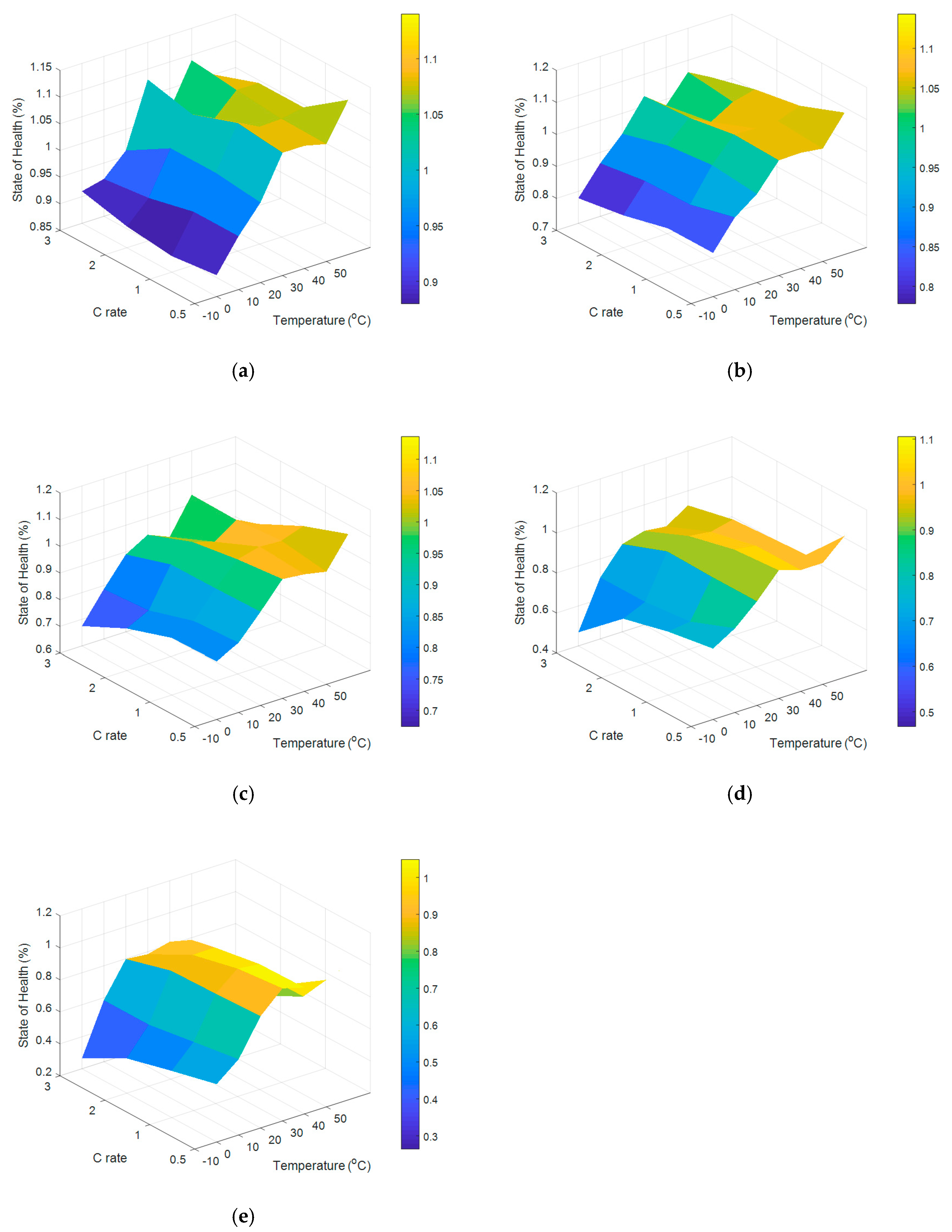
Under environmental temperatures of 20 and 30 °C, the results of 400 cycles of different discharge rates are listed in Table 1. The experimental results indicate that at the 400th cycle for rates 0.5, 1, and 2 C, the SoHN is still higher than 93%. For 3 C rate at the 400th cycle, the SoHN is lower than 80%. At 20 and 30 °C, the battery performance is very stable and with a very long cycle life. The work in [50] has shown that the discharge capacity measured at 25 °C shows 15.5% loss after 600 cycles; the experimental results are similar to the references [50,51,52]. Since over 2000 charge and discharge cycles are expected to be undergone by the LiFePO4 battery, considering the experimental cost, the number of battery tests was set to 400 cycles.
At 40 °C and 50 °C, the results of 400 cycles of different discharge rates are listed in Table 2. Under high temperature, owing to rapid electrochemical reactions, the CE increases. After 400 cycles at 50 °C and with a 0.5 C rate, SoHN still has a value of 104.83%. When the discharge rate is raised to 3 C, it can be seen that SoHN drops rapidly at 400 cycles to only 49.33%. The experimental results indicate that under working conditions of 50 °C and a 3 C rate, the battery life will quickly decay.
Under environmental temperatures of −10, 0, and 10 °C, the results of 400 cycles of different discharge rates are listed in Table 3. Under low temperature CE is not high. With −10 °C and 3 C rate as example of the working condition, at the first cycle the SoHN is only about 91.08%. As the number of cycles increase, the compound influence from low temperature and high discharge rates gradually become obvious. At 400 cycles, the SoHN is only 26.4%, far lower than the battery life under room temperature. This indicates that under low temperature the CE of LiFePO4 is not high and the capacity fades rapidly.

2.4. Parameter Analysis and Comparison

Analyzing the discharge time and voltage plateau curves, it can be observed that at 20, 30, 40, and 50 °C, the influence of high discharge rate to the CE is minor. However, under a high temperature environment, as the Ohmic heating from the increase in number of cycles and high discharge rate rapidly damages the internal materials of the battery; the capacity will quickly decrease. Under low temperature, the rate of electrochemical reactions lowers; by necessity the CE must also fall. However, under an environment of low temperature together with high discharge rate, Ohmic heating will offset some influence from low temperature, allowing the CE to increase slightly. It can be observed from Figure 2a–d that the discharge curves are not stable. However, as the number of cycles increases, due to uneven heating of internal materials of the battery, those close to the battery tip decay more quickly. Hence, there will be a much greater capacity fade compared to prediction.
It can be seen that under the compound influence of environmental temperature and discharge rate, there will be huge changes to discharging time and capacity fade. From Table 1, Table 2 and Table 3, Figure 3a–e were constructed. From the figures, the influence of temperature and discharge rate on capacity can be clearly seen. The CE represents the battery performance, while the remaining capacity represents the life of the battery. These two are very important to battery safety. Hence, battery characteristics must be obtained from changes of the CE and remaining capacity under different temperatures, discharge rates, and numbers of cycles to establish a comprehensive battery model to ensure that the battery can operate safely.

3. Comprehensive Model Development

3.1. Thevenin Equivalent Circuit Model

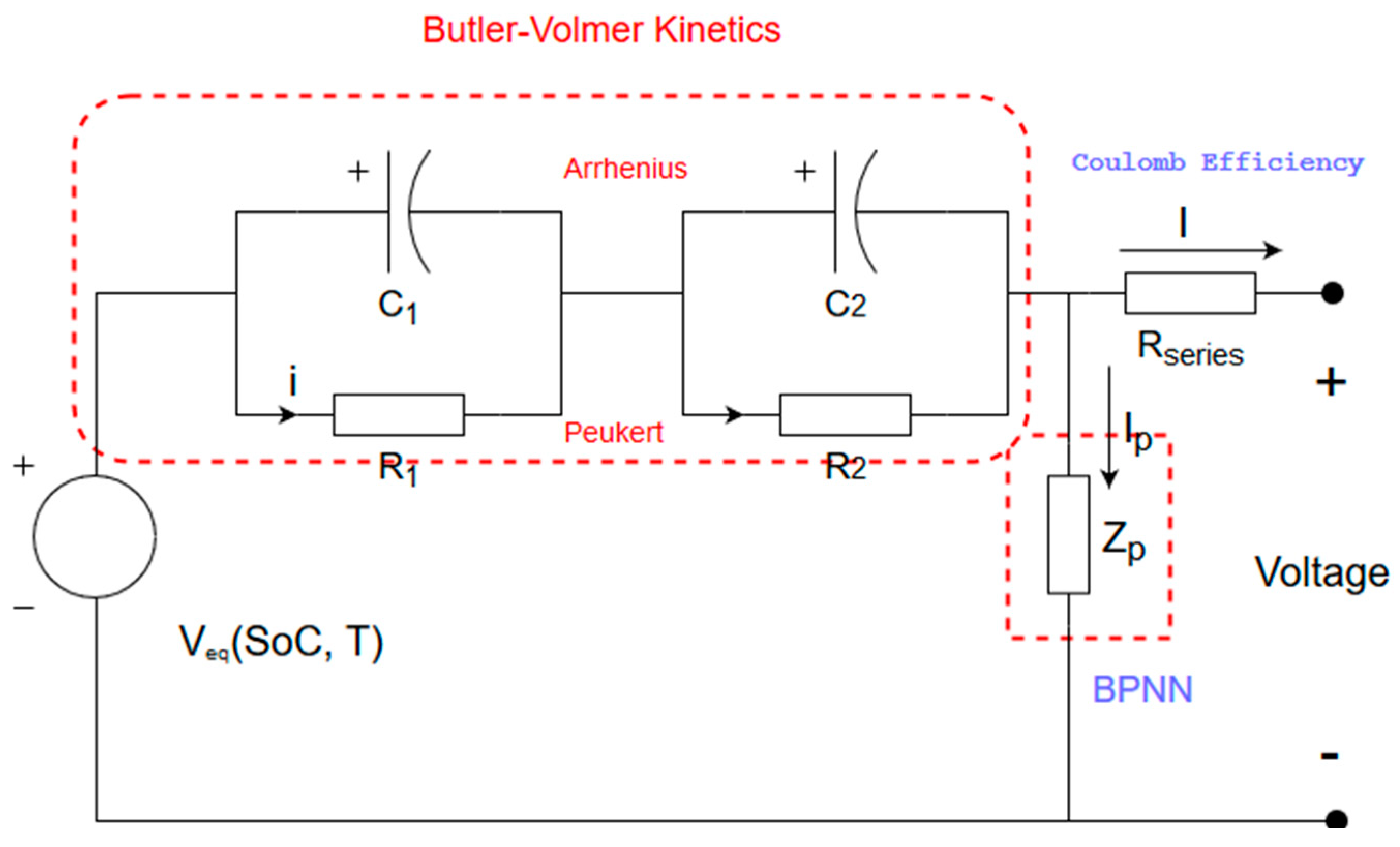
The equivalent circuit model is commonly used in predicting battery function and providing estimation to the battery management system [53,54].Figure 4a shows the battery’s open-circuit voltage (OCV)-SoC characteristics. Figure 4b shows the battery’s voltage-current characteristics. The battery models in Figure 4a,b are quite accurate, since they can clearly describe the battery’s nonlinear dynamic behavior, which can be used as a good solution for the SoC estimation of energy storage devices.
The equivalent circuit model can be represented by the following state equations [36,37,53,54], where Vps and Vpf are the state variables, Ib is the input, and Vb the output:
V ˙ p f = 1 R 1 C 1 V p f 1 C 1 I b ; V ˙ p s = 1 R 2 C 2 V p s 1 C 2 I b ; V b = V o c + V p s + V p f + R d I b ,
where Vb is the voltage at the battery terminals, Ib is the current flowing through the battery, Voc is the open circuit voltage, Rb is the internal resistance, R1 and C1 comprise the fast resistor–capacitor (RC) network, R2 and C2 comprise the slow RC network, Vpf is the voltage across the fast RC network, and Vps is the voltage across the slow RC network.
Overall, the equivalent-circuit model is described by the two RC networks shown in Figure 4b. The slow RC network dominates when the battery is nearly full, in which case the discharging behavior is fairly stable. The fast RC network dominates when the battery is running low—during the unstable discharging behavior.
The proposed model is used to estimate the battery’s SoC and the remaining capacity by considering the battery model’s parameters, and the available states are Vb, Ib, and temperature. Therefore, the simplifications of the electrochemistry equations make it possible to integrate it using equivalent circuit models.

3.2. Butler–Volmer Equation

Capturing of the battery’s dynamic responses can be done through the equivalent circuit model descriptions. For the battery’s electrochemical reaction phenomena, Butler–Volmer kinetic equation descriptions can be employed, as shown in (5). Charge transfer kinetics of lithium intercalation obeys the Butler–Volmer equation [55,56,57]. It describes the current from basic electrochemical reactions varying with activation overvoltage η a c t , such that
J = J 0 · { e [ α q η a c t k B T ] e [ ( α 1 ) q η a c t k B T ] } ,
where J is the electrode current density in A/m2, J 0 is the exchange current density in A/m2, η a c t is the surface overpotential in volts, k B is Boltzmann constant, T is the absolute temperature, q = 1.602 × 10 19 (C), α is the anodic charge transfer coefficient, and ( α 1 ) is the cathodic charge transfer coefficient, where α is assumed to be 0.5 in a battery.
The surface overpotential is as follows: η a c t = ( E E r e v ) , where E is the difference of the mean electrostatic potentials of ions and electronsand Erev is the Nernst equilibrium potential, which is strongly related to the local activity of lithium.
Closed circuit voltage (CCV) is defined as V = Videal η a c t , where Videal is he standard potential defined by the open circuit voltage plateau (Videal = 3.42 V for Li metal) [5]. The size of η a c t is dependent on reaction kinetics, meaning J 0 influences η a c t and it is in turn affected by the reaction temperature. η a c t represents the voltage loss necessary in overcoming the activation energy barrier of electrochemical reactions. Thus, to obtain a greater current from the battery, a larger voltage loss is inevitable. Changes in electro-chemical reactions can be seen as changes in kinetic parameters, such as α and J 0 . If J 0 is low for any specific net current, the kinetics will become sluggish and the activation overvoltage will be even greater. If J 0 is large, a large current can be supplied. In [58], it was stated that since J 0 is difficult to be measured from the outside, Equation (5) can be rewritten as:
1 J 0 · S · I ( t ) = [ e [ α q η a c t k B T ] e [ ( α 1 ) q η a c t k B T ] ] ;
I ( t ) = J ( t ) · S ,
where S is the effective area.
In [54], the overvoltage η a c t ( t ) caused by current variation is represented as:
η a c t ( t ) = 2 R T F ln ( 1 2 J 0 · S · I ( t ) + ( 1 2 J 0 · S · I ( t ) ) 2 + 1 )
Although there are still a variety of electrochemical variables that cannot be obtained externally, it is possible to acquire a specific change of potential excited by diverse currents. Thus, it can be seen that J 0 and S are closely related to SoC, reflecting the complexity during the polarization establishment. Increasing the current while fixing other available variables will result in a sharp deviation from the equilibrium state.

3.3. Arrhenius and Peukert Laws

The relationship between the CE and temperature follows the Arrhenius’ law [10] in
k a = A · e E a / R T ;
Q l o s s = 1 Q Q 0 ,
where k a is the rate constant, T is the absolute temperature, A is a constant for each chemical reaction known as the pre-exponential factor, E a is the activation energy for the reaction, R is the universal gas constant, Q l o s s is the ratio of capacity loss, Q is the actual capacity of the battery, and Q 0 is the battery’s initial capacity.
When the battery’s discharge current increases, the side effect produced is termed Ohmic heating, meaning part of the energy is wasted as heat. Simultaneously, it also increases Ohmic loss. The rate of ions diffusing and migrating at the poles is lower than the increased discharge current, leading to a lower recovery rate. Finally, it results in a smaller battery capacity. Thus, Peukert’s law [23] aims at correcting the relationship between the discharge current and capacity, such that
C t = I u t ,
where C t is the capacity at a one-ampere discharge rate, which must be expressed in ampere hours; I is the actual discharge current in amperes; t is the actual time to discharge the battery; and u is the Peukert constant.
The Peukert constant can be used to evaluate the performance of a battery, like the secondary chemical reactions resulting from battery discharging at a high rate. The materials’ structures change as the impedance increases. However, u is still close to 1 [59].

4. Results

4.1. Analysis and Modeling with the Comprehensive Model

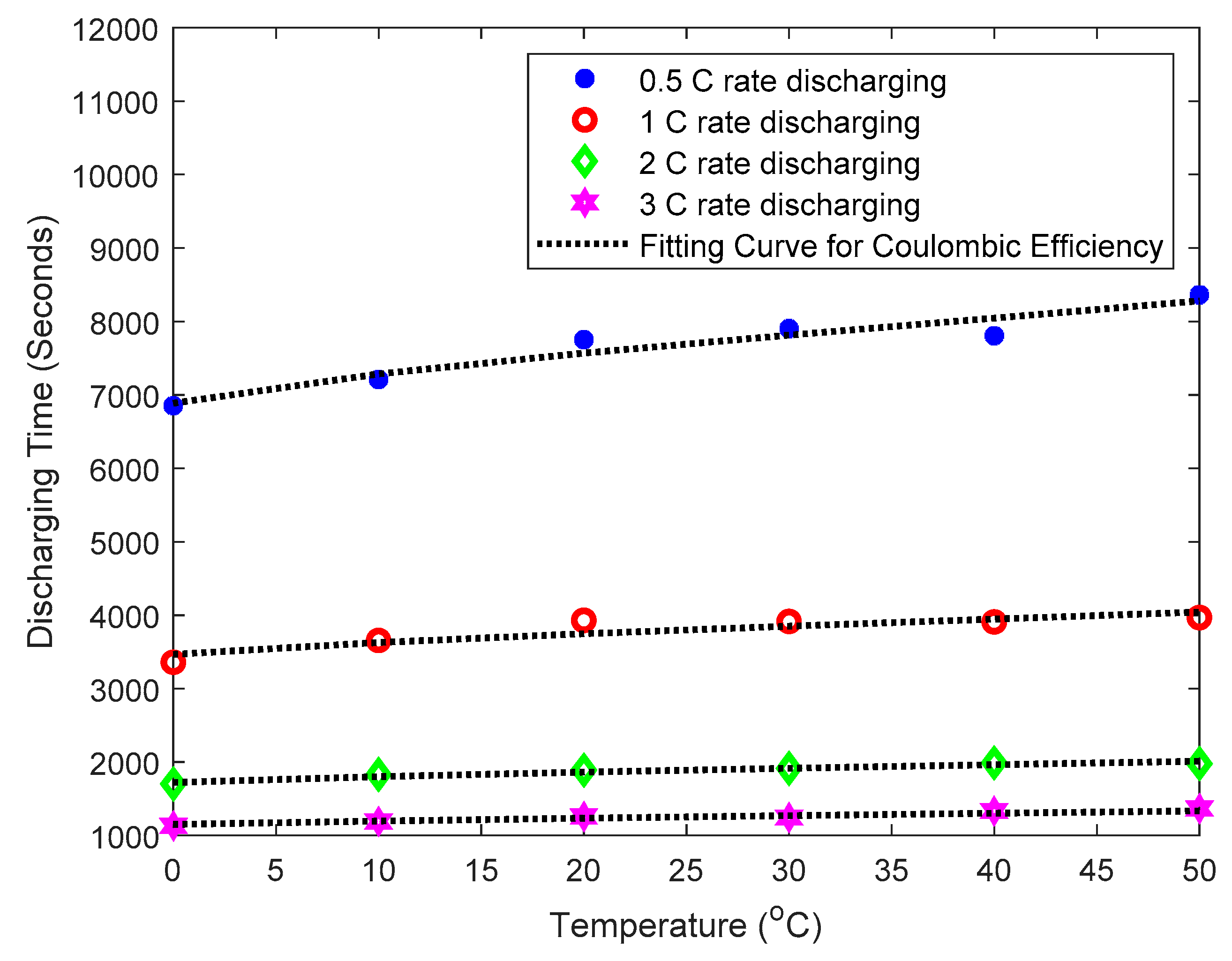
From the battery discharging behaviors of Figure 2a–d, fitting curves for the variation of the end of discharging time can be constructed. It is easier to observe the temperature and current dependence of the CE graphically. The curve fitting results are shown in Figure 5, which depicts the difference between measured results and fitted curves. Since the relationship of the CE and temperature in the equivalent circuit model follows the Arrhenius law, while the current obeys Peukert’s law, the CE of the equation has the form of:
η c ( T ) = a 1 · e ( b 1 · T ) + a 2 · e ( b 2 · T )
where T is the temperature, and a 1 , b 1 , a 2 , and b 2 are the fitteing parameters.
The parameters a 1 , b 1 , a 2 , and b 2 of the batteries measured are plotted in Figure 6. It can be clearly seen that the parameters vary with Peukert’s law. By observing the trends of the parameters under the same temperature and different discharge currents in Figure 6, the parameters can be fitted to:
a 1 ( I ) = p 1 · I k 1 b 1 ( I ) = p 2 · I k 2 a 2 ( I ) = p 3 · I k 3 b 2 ( I ) = p 4 · I k 4
where I is discharging current; parameters p 1 , p 2 , p 3 , and p 4 , k 1 , k 2 , k 3 , and k 4 are fitting parameters. The values are lised in Table 4.
By incorporating all the values of Table 4 for Equation (13) to find the related parameters p 1 , p 2 , p 3 , and p 4 , k 1 , k 2 , k 3 , and k 4 , we can obtain the predicted values of the parameters a 1 , b 1 , a 2 , and b 2 for Equation (12).
Equation (12) is composed of two exponential terms, which correspond to the pair of RC circuits in Figure 4b, where an exponential term represents the slow RC network; the other exponential term represents the fast RC network.
Comparing the experimental results to Equations (12) and (13), the mean absolute percentage errors (MAPE) defined as
M A P E = t = 1 n | A t F t A t | n · 100 %
are listed in Table 5. In Equation (14), At is the measured data of cycle 1 of Table 1, Table 2 and Table 3, Ft is the fitted data, and n the number of data readings.

4.2. Using Artificial Neural Networks to Estimate Remaining Capacity

The CE variation under variable working conditions can be estimated by Equations (12) and (13). When a battery discharges under various environmental conditions during certain cycles, the capacity fades. Without correction, the estimation errors of Equation (1) increase gradually with the operating cycle. Therefore, by introducing the correction of the CE and considering the declination of SoH, the estimation error is effectively reduced.
Considering Equations (2) and (3), Q a v a i l a b l e represents the available capacity of a battery, which is influenced by the CE. C m a x , p represents the remaining capacity of a battery, which is not influenced by the CE. In order to obtain the true remaining capacity of a battery, the data of Table 2, Table 3 and Table 4 were normalized through Equation (15).
C m a x , p = Q a v a i l a b l e η c ( T )
The estimation of SoHN would normally be based on the relationship between charging/discharging cycles and remaining capacity. However, considering actual usage scenarios, such as in electric vehicles and other energy storage devices, the discharge C rate would vary sharply in a short period. Moreover, it is difficult for full charging and discharging to take place. Compound effects under different temperatures and discharge rates on capacity fade are difficult to estimate. Thus, this method cannot be direct applied to scenarios where large variations in environmental parameters exist. Therefore, the charging/discharging cycle numbers of the battery were normalized under different usage environments as discharging times in seconds. Through this method, the accumulated degradation of the batteries under various environments was analyzed. When the battery had undergone various rates of discharge under different temperatures, the remaining capacity was calculated by the ANN.
The learning ability of ANN was realized by means of model training. The common training algorithm is a back-propagation algorithm, which means that the network error will be propagated back if it does not reach an expected value in the model training process; meanwhile, the network weights and biases values are adjusted constantly to obtain the minimum error [60]. This research utilized a multi-layered BPNN to study the model for estimating the remaining capacity ( C m a x , p ). The network was trained using battery datasets collected under varying temperatures and discharging currents. To build the BPNN model, the complete data was split into training (70%) and testing (30%) data. The detailed operation flow of the BPNN is described below.
The BPNN is one of the most commonly used neural network models. It is a multi-layer feedforward network that can learn and store base on the training of error back propagation. Its rule of learning makes use of gradient descent. Through continual adjustments of back propagation weights and thresholds of the whole network, the network’s error square summation (cost) is minimized [60]. Moreover, BPNN can get many input-output models without the knowledge of mathematical equations of the mapping relationship [61].
In experiments, the irreversible capacity fade ( C f a d e ) of the battery is influenced by discharging current (i), ambient temperature (T), and cumulative discharging time (cdt). The typical C f a d e algorithm is as follows:
C f a d e = f ( i , T , c d t ) .
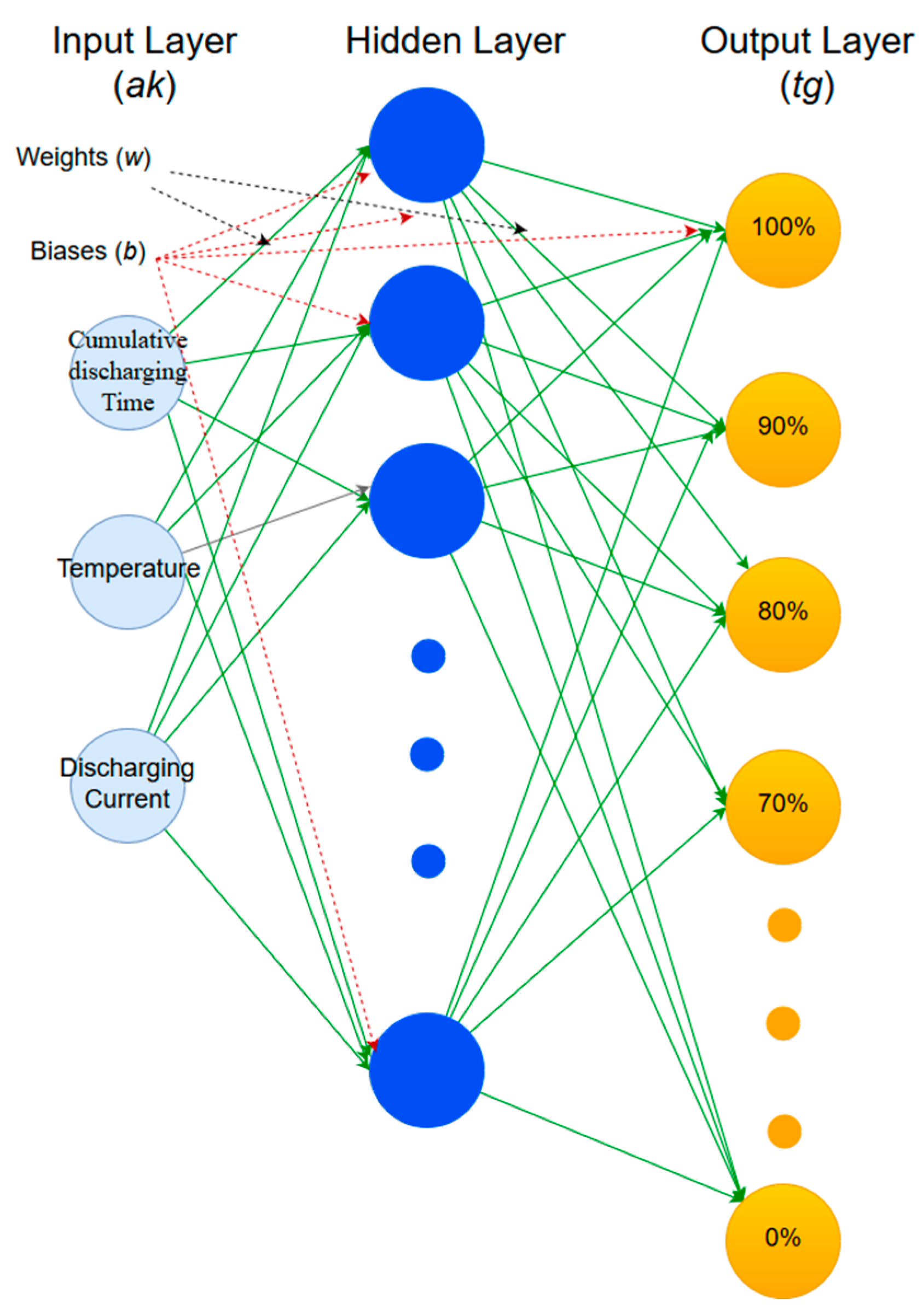
Through Equation (16), the topographical structure of BPNN includes: (1) an input layer: input variables, including (T), (i), and (cdt); (2) one or more hidden layers; (3) an output layer. This model is shown graphically in Figure 7.
The parameter ak represents the data input to the model in the Figure 7; tg represents the model output result, which is the remaining capacity of a battery; and w and b are the weight and bias values, respectively. There are three nodes in the input layer. According to Kolmogorov rule [62,63], the number of neurons was set as seven in the hidden layer. The activation function selected for the model construction was log-sigmoid in last two layers [64], written as
f ( n ) = 1 1 + e n .
The output value (tg) of each neuron (j) in the hidden layer was calculated by
t g i = f ( i = 1 3 a k i w i , j + b j ) ,   i = 1 , , 3 ,   j = 1 , , 7 ,
where a k i represents the input vector, w i , j is the weight value connecting the ith input vector and the jth neuron, b j represents bias values, and f represents log-sigmoid activation function. The model output tg can be calculated from
t g v = f ( j = 1 7 g j w j , v + b v ) ,   v = 1 ,
where v is the number of neurons in the output layer.
In this study, a variant of the gradient descent method called the Levenberg–Marquardt (LM) algorithm was employed to train the constructed model [62,65]. The LM algorithm integrates together, the gradient descent method and the Newton method, which can solve non-linear least squares problems. When it is used for ANN training, the iteration can continue to proceed quickly while ensuring model training speed and accuracy. Finally, the prediction values of remaining capacity were attained finally through the above modeling.

4.3. Establishing the Comprehensive Model

This research utilizes the Butler–Volmer equation and the Arrhenius and Peukert laws. In order to express these phenomena in an equivalent circuit model, this research proposed simplification with parameter fitting. In our model, the Butler–Volmer equation describes the voltage and current characteristics of the battery while the temperature and discharging current are modeled by the Arrhenius and Peukert laws. Capacity fade, caused by the compound influence of various operating environments, is calculated by BPNN. Thus, the significance of the equivalent circuit model can be explained as in Figure 8. In the figure, the CE is determined by the two RC networks and the BPNN-modelled capacity fade.

5. Discussions and Verification

Temperature and discharging current are critical parameters in modelling battery dynamics and have been proven to have a significant influence on SoC and remaining capacity estimations. The battery may operate under varying temperatures, including seasonal changes and day/night cycles. The heat generated during the discharge processes will also influence the battery’s surface temperatures. In this section, we describe the comprehensive model proposed being tested by the data collected, under varying conditions.
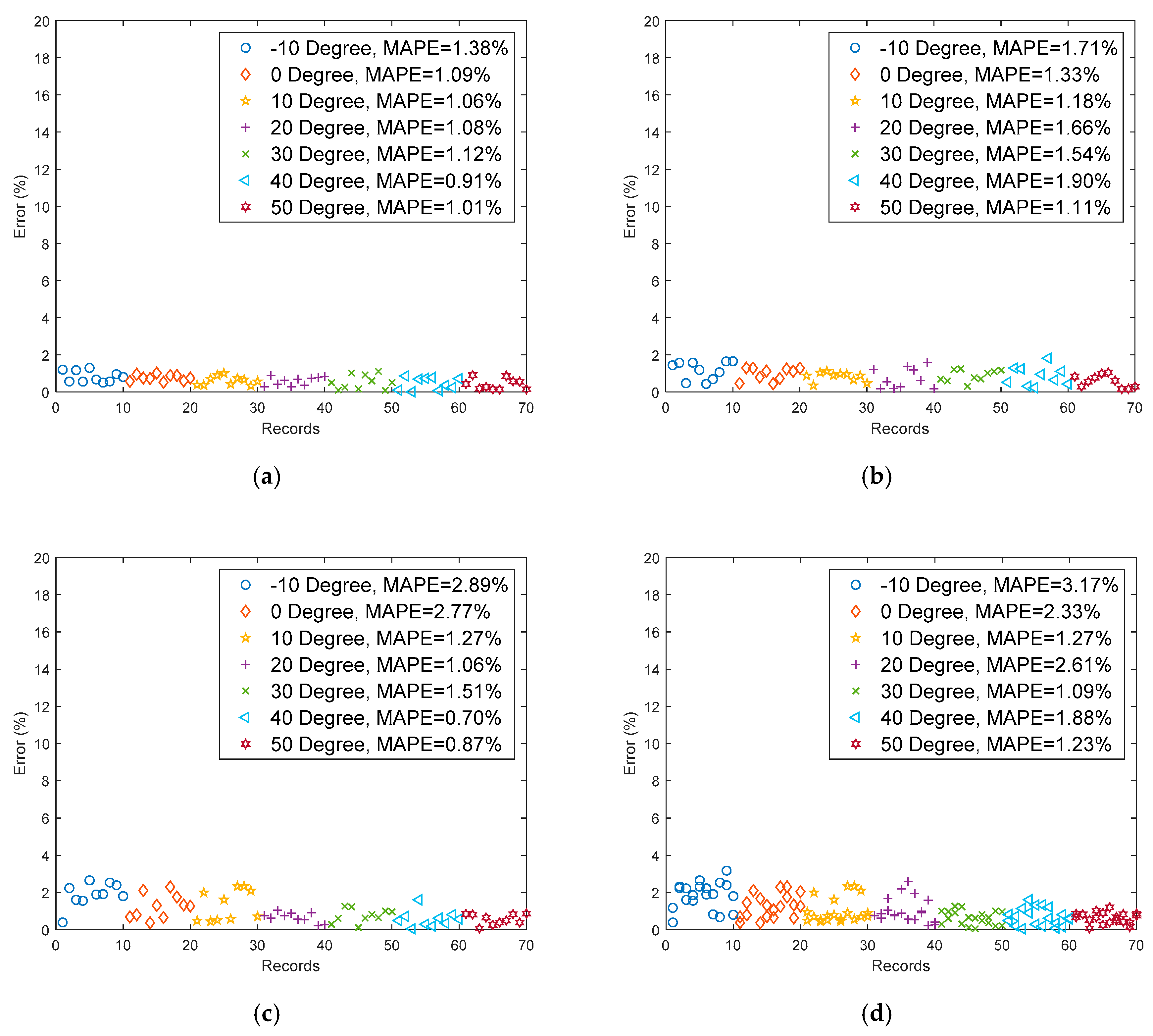
The comprehensive model simultaneously considers the influence of the CE and remaining capacity. In order to verify the correctness of the model, the mean absolute percentage errors (MAPEs) of all tested cases are shown in Figure 9. Overall, the proposed model provides an acceptable estimation result with an MAPE of 1.55% for all the cases tested. As in Figure 9, under room and high temperatures, the proposed model gives a quite satisfying SoC estimation. The estimated SoC are close to the true value, with almost all of the estimation errors being less than 2%. For the SoC estimation under low temperatures, MAPEs vary from 1.06% to 3.71%. It is easily seen from Figure 9d that the estimated SoCs slightly deviate from the true values. As the battery dynamics at low temperature and large C rate are more complicated, SoC estimation is much more difficult. To improve the estimation performance at low temperatures, one practical solution is to increase the amount of training data, particularly for batteries working at low temperatures.

6. Conclusions

Coulombic efficiency and remaining capacity are the indicators for estimating battery performance and available capacity, respectively. To ensure safe operation and prevent excessive discharge, accurate SoC and SoH estimations are very important for lithium ion batteries. Thus, much research has been conducted to resolve these issues and increase battery performance. As battery manufacturing technology continues to progress, lithium ion batteries are used more and more. When the battery is discharging at a high rate under a low temperature, the heat produced during discharge will offset some influences from the environmental temperature. As a result, after discharging for a certain length of time, the amount of power delivered will drop while the voltage will conversely rise. In that case, SoC estimates voltage of battery with large errors. As the environmental temperature rises, the battery performance is visibly initially better than that under room temperature or low temperature. However, the battery’s cycle life would be lower than that under room temperature. Therefore, under the processes of cyclic charging and discharging, different currents and temperatures produce significant changes in battery capacity. These factors must be considered for the implementation of the battery management system (BMS).
This research used LiFePO4 batteries with 10 Ah capacity and 3.2 V rated voltage for testing under various temperatures and discharge rates. Under testing conditions of 400 cycles, the discharge voltages and currents of the batteries during the discharge process were recorded. The batteries were analyzed with different degrees of aging and their corresponding characteristics were gathered. The comprehensive model was able to follow the temperature and current changes to precisely estimate the SoC of the LiFePO4 battery. The results obtained indicate that the average error of the comprehensive model under various current loads and temperatures to be only 1.55%.
The LiFePO4 batteries are manufactured in the same factory and should have a high degree of consistency. Therefore, when the error of one battery is higher than the rest, it can be considered a signal that the battery capacity is fading faster than before, indicating that the battery should be replaced immediately. Due to the model accuracy and stability shown during this paper, the model can be considered a useful tool for the control and performance analysis of a management system which includes a Li-ion battery.

Funding

This research received no external funding.

Conflicts of Interest

The author declares no conflict of interest.

References

  1. Kurzweil, P.; Brandt, K. Secondary batteries–lithium rechargeable systems| Overview. In Encyclopedia of Electrochemical Power Sources; Newnes: Oxford, UK, 2009; pp. 1–26. [Google Scholar]
  2. Garche, J.; Dyer, C.K.; Moseley, P.T.; Ogumi, Z.; Rand, D.A.; Scrosati, B. Encyclopedia of Electrochemical Power Sources; Newnes: Oxford, UK, 2013. [Google Scholar]
  3. Ali, M.U.; Zafar, A.; Nengroo, S.H.; Hussain, S.; Alvi, M.J.; Kim, H.J.J.E. Towards a Smarter Battery Management System for Electric Vehicle Applications: A Critical Review of Lithium-Ion Battery State of Charge Estimation. Energies 2019, 12, 446. [Google Scholar] [CrossRef]
  4. Miao, Y.; Hynan, P.; von Jouanne, A.; Yokochi, A.J.E. Current Li-Ion Battery Technologies in Electric Vehicles and Opportunities for Advancements. Energies 2019, 12, 1074. [Google Scholar] [CrossRef]
  5. Bai, P.; Cogswell, D.A.; Bazant, M.Z. Suppression of phase separation in LiFePO(4) nanoparticles during battery discharge. Nano Lett. 2011, 11, 4890–4896. [Google Scholar] [CrossRef] [PubMed]
  6. Chan, H.L. A new battery model for use with battery energy storage systems and electric vehicles power systems. In Proceedings of the 2000 IEEE Power Engineering Society Winter Meeting. Conference Proceedings (Cat. No.00CH37077), Singapore, 23–27 January 2000; Volume 1, pp. 470–475. [Google Scholar] [CrossRef]
  7. Chen, M.; Rincon-Mora, G.A. Accurate Electrical Battery Model Capable of Predicting Runtime and I–V Performance. IEEE Trans. Energy Convers. 2006, 21, 504–511. [Google Scholar] [CrossRef]
  8. Dargaville, S.; Farrell, T.W. Predicting Active Material Utilization in LiFePO4 Electrodes Using a Multiscale Mathematical Model. J. Electrochem. Soc. 2010, 157, A830–A840. [Google Scholar] [CrossRef]
  9. Kuo, T.J.; Lee, K.Y.; Huang, C.K.; Chen, J.H.; Chiu, W.L.; Huang, C.F.; Wu, S.D. State of charge modeling of lithium-ion batteries using dual exponential functions. J. Power Sources 2016, 315, 331–338. [Google Scholar] [CrossRef]
  10. Sun, S.; Guan, T.; Shen, B.; Leng, K.; Gao, Y.; Cheng, X.; Yin, G. Changes of Degradation Mechanisms of LiFePO 4 /Graphite Batteries Cycled at Different Ambient Temperatures. Electrochim. Acta 2017, 237, 248–258. [Google Scholar] [CrossRef]
  11. Wang, J.; Yang, J.; Tang, Y.; Li, R.; Liang, G.; Sham, T.K.; Sun, X. Surface aging at olivine LiFePO4: A direct visual observation of iron dissolution and the protection role of nano-carbon coating. J. Mater. Chem. A 2013, 1, 1579–1586. [Google Scholar] [CrossRef]
  12. Chang, W.; Kim, S.J.; Park, I.T.; Cho, B.W.; Chung, K.Y.; Shin, H.C. Low temperature performance of LiFePO4 cathode material for Li-ion batteries. J. Alloys Compd. 2013, 563, 249–253. [Google Scholar] [CrossRef]
  13. Zhang, S.S.; Xu, K.; Jow, T.R. A new approach toward improved low temperature performance of Li-ion battery. Electrochem. Commun. 2002, 4, 928–932. [Google Scholar] [CrossRef]
  14. Abraham, D.P.; Heaton, J.R.; Kang, S.H.; Dees, D.W.; Jansen, A.N. Investigating the Low-Temperature Impedance Increase of Lithium-Ion Cells. J. Electrochem. Soc. 2008, 155, A41. [Google Scholar] [CrossRef]
  15. Maheshwari, A.; Heck, M.; Santarelli, M. Cycle aging studies of lithium nickel manganese cobalt oxide-based batteries using electrochemical impedance spectroscopy. Electrochim. Acta 2018, 273, 335–348. [Google Scholar] [CrossRef]
  16. Anseán, D.; Dubarry, M.; Devie, A.; Liaw, B.Y.; García, V.M.; Viera, J.C.; González, M. Operando lithium plating quantification and early detection of a commercial LiFePO4 cell cycled under dynamic driving schedule. J. Power Sources 2017, 356, 36–46. [Google Scholar] [CrossRef] [Green Version]
  17. Waldmann, T.; Wilka, M.; Kasper, M.; Fleischhammer, M.; Wohlfahrt-Mehrens, M. Temperature dependent ageing mechanisms in Lithium-ion batteries—A Post-Mortem study. J. Power Sources 2014, 262, 129–135. [Google Scholar] [CrossRef]
  18. Agubra, V.; Fergus, J.J.M. Lithium ion battery anode aging mechanisms. Materials 2013, 6, 1310–1325. [Google Scholar] [CrossRef]
  19. Hendricks, C.; Williard, N.; Mathew, S.; Pecht, M. A failure modes, mechanisms, and effects analysis (FMMEA) of lithium-ion batteries. J. Power Sources 2015, 297, 113–120. [Google Scholar] [CrossRef] [Green Version]
  20. Song, W.; Chen, M.; Bai, F.; Lin, S.; Chen, Y.; Feng, Z. Non-uniform effect on the thermal/aging performance of Lithium-ion pouch battery. Appl. Therm. Eng. 2018, 128, 1165–1174. [Google Scholar] [CrossRef]
  21. Yao, X.Y.; Pecht, M.G. Tab Design and Failures in Cylindrical Li-ion Batteries. IEEE Access 2019, 7, 24082–24095. [Google Scholar] [CrossRef]
  22. Ko, S.T.; Lee, J.; Ahn, J.H.; Lee, B.K.J.E. Innovative Modeling Approach for Li-Ion Battery Packs Considering Intrinsic Cell Unbalances and Packaging Elements. Energies 2019, 12, 356. [Google Scholar] [CrossRef]
  23. Li, J.; Zhang, J.; Zhang, X.; Yang, C.; Xu, N.; Xia, B. Study of the storage performance of a Li-ion cell at elevated temperature. Electrochim. Acta 2010, 55, 927–934. [Google Scholar] [CrossRef]
  24. Guan, T.; Sun, S.; Gao, Y.; Du, C.; Zuo, P.; Cui, Y.; Zhang, L.; Yin, G. The effect of elevated temperature on the accelerated aging of LiCoO 2 /mesocarbon microbeads batteries. Appl. Energy 2016, 177, 1–10. [Google Scholar] [CrossRef]
  25. Kassem, M.; Delacourt, C. Postmortem analysis of calendar-aged graphite/LiFePO4 cells. J. Power Sources 2013, 235, 159–171. [Google Scholar] [CrossRef]
  26. Smith, A.J.; Burns, J.C.; Trussler, S.; Dahn, J.R. Precision Measurements of the Coulombic Efficiency of Lithium-Ion Batteries and of Electrode Materials for Lithium-Ion Batteries. J. Electrochem. Soc. 2010, 157, A196–A202. [Google Scholar] [CrossRef]
  27. Bond, T.M.; Burns, J.C.; Stevens, D.A.; Dahn, H.M.; Dahn, J.R. Improving Precision and Accuracy in Coulombic Efficiency Measurements of Li-Ion Batteries. J. Electrochem. Soc. 2013, 160, A521–A527. [Google Scholar] [CrossRef]
  28. Santhanagopalan, S.; White, R.E. Online estimation of the state of charge of a lithium ion cell. J. Power Sources 2006, 161, 1346–1355. [Google Scholar] [CrossRef]
  29. Huang, S.C.; Tseng, K.H.; Liang, J.W.; Chang, C.L.; Pecht, M.G. An Online SOC and SOH Estimation Model for Lithium-Ion Batteries. Energies 2017, 10, 512. [Google Scholar] [CrossRef]
  30. Berrueta, A.; Urtasun, A.; Ursúa, A.; Sanchis, P. A comprehensive model for lithium-ion batteries: From the physical principles to an electrical model. Energy 2018, 144, 286–300. [Google Scholar] [CrossRef] [Green Version]
  31. Tippmann, S.; Walper, D.; Balboa, L.; Spier, B.; Bessler, W.G. Low-temperature charging of lithium-ion cells part I: Electrochemical modeling and experimental investigation of degradation behavior. J. Power Sources 2014, 252, 305–316. [Google Scholar] [CrossRef]
  32. Salvadori, A.; Grazioli, D.; Geers, M.G.D. Governing equations for a two-scale analysis of Li-ion battery cells. Int. J. Solids Struct 2015, 59, 90–109. [Google Scholar] [CrossRef]
  33. Gu, L.; Xiao, D.; Hu, Y.S.; Li, H.; Ikuhara, Y. Atomic-scale structure evolution in a quasi-equilibrated electrochemical process of electrode materials for rechargeable batteries. Adv. Mater. 2015, 27, 2134–2149. [Google Scholar] [CrossRef]
  34. Fuller, T.F.; Doyle, M.; Newman, J. Relaxation Phenomena in Lithium-Ion-Insertion Cells. J. Electrochem. Soc. 1994, 141, 982–990. [Google Scholar] [CrossRef]
  35. Singh, M.; Kaiser, J.; Hahn, H. Effect of Porosity on the Thick Electrodes for High Energy Density Lithium Ion Batteries for Stationary Applications. Batteries 2016, 2, 35. [Google Scholar] [CrossRef]
  36. Petzl, M.; Danzer, M.A. Advancements in OCV Measurement and Analysis for Lithium-Ion Batteries. IEEE Trans. Energy Convers. 2013, 28, 675–681. [Google Scholar] [CrossRef]
  37. Chaoui, H.; Ibe-Ekeocha, C.C.; Gualous, H. Aging prediction and state of charge estimation of a LiFePO 4 battery using input time-delayed neural networks. Electr. Power Syst. Res. 2017, 146, 189–197. [Google Scholar] [CrossRef]
  38. Khumprom, P.; Yodo, N.J.E. A Data-Driven Predictive Prognostic Model for Lithium-Ion Batteries based on a Deep Learning Algorithm. Energies 2019, 12, 660. [Google Scholar] [CrossRef]
  39. Wang, Y.J.; Yang, D.; Zhang, X.; Chen, Z.H. Probability based remaining capacity estimation using data-driven and neural network model. J. Power Sources 2016, 315, 199–208. [Google Scholar] [CrossRef]
  40. Dong, G.Z.; Zhang, X.; Zhang, C.B.; Chen, Z.H. A method for state of energy estimation of lithium-ion batteries based on neural network model. Energy 2015, 90, 879–888. [Google Scholar] [CrossRef]
  41. Hu, X.S.; Li, S.B.; Peng, H. A comparative study of equivalent circuit models for Li-ion batteries. J. Power Sources 2012, 198, 359–367. [Google Scholar] [CrossRef]
  42. Wang, Q.K.; He, Y.J.; Shen, J.N.; Ma, Z.F.; Zhong, G.B. A unified modeling framework for lithium-ion batteries: An artificial neural network based thermal coupled equivalent circuit model approach. Energy 2017, 138, 118–132. [Google Scholar] [CrossRef]
  43. Jokar, A.; Désilets, M.; Lacroix, M.; Zaghib, K. Mesoscopic modeling and parameter estimation of a lithium-ion battery based on LiFePO4/graphite. J. Power Sources 2018, 379, 84–90. [Google Scholar] [CrossRef]
  44. Saxena, S.; Kang, M.; Xing, Y.; Pecht, M. Anomaly Detection During Lithium-ion Battery Qualification Testing. In Proceedings of the 2018 IEEE International Conference on Prognostics and Health Management (ICPHM), Seattle, WA, USA, 11–13 June 2018; pp. 1–6. [Google Scholar]
  45. Diao, W.; Saxena, S.; Han, B.; Pecht, M. Algorithm to Determine the Knee Point on Capacity Fade Curves of Lithium-Ion Cells. Energies 2019, 12. [Google Scholar] [CrossRef]
  46. Razavi-Far, R.; Farajzadeh-Zanjani, M.; Chakrabarti, S.; Saif, M. Data-driven prognostic techniques for estimation of the remaining useful life of lithium-ion batteries. In Proceedings of the 2016 IEEE International Conference on Prognostics and Health Management (ICPHM), Ottawa, ON, Canada, 20–22 June 2016; pp. 1–8. [Google Scholar]
  47. Jiang, J.; Gao, Y.; Zhang, C.; Zhang, W.; Jiang, Y. Lifetime Rapid Evaluation Method for Lithium-Ion Battery with Li(NiMnCo)O2 Cathode. J. Electrochem. Soc. 2019, 166, A1070–A1081. [Google Scholar] [CrossRef]
  48. Kennedy, B.; Patterson, D.; Camilleri, S. Use of lithium-ion batteries in electric vehicles. J. Power Sources 2000, 90, 156–162. [Google Scholar] [CrossRef]
  49. Zhang, T.; Fuchs, B.; Secchiaroli, M.; Wohlfahrt-Mehrens, M.; Dsoke, S. Electrochemical behavior and stability of a commercial activated carbon in various organic electrolyte combinations containing Li-salts. Electrochim. Acta 2016, 218, 163–173. [Google Scholar] [CrossRef]
  50. Zhang, Y.C.; Wang, C.Y.; Tang, X.D. Cycling degradation of an automotive LiFePO4 lithium-ion battery. J. Power Sources 2011, 196, 1513–1520. [Google Scholar] [CrossRef]
  51. Wang, J.; Liu, P.; Hicks-Garner, J.; Sherman, E.; Soukiazian, S.; Verbrugge, M.; Tataria, H.; Musser, J.; Finamore, P. Cycle-life model for graphite-LiFePO4 cells. J. Power Sources 2011, 196, 3942–3948. [Google Scholar] [CrossRef]
  52. Shim, J.; Striebel, K.A. Cycling performance of low-cost lithium ion batteries with natural graphite and LiFePO4. J. Power Sources 2003, 119, 955–958. [Google Scholar] [CrossRef]
  53. Tran, N.T.; Khan, A.; Nguyen, T.T.; Kim, D.W.; Choi, W.J.E. SOC Estimation of Multiple Lithium-Ion Battery Cells in a Module Using a Nonlinear State Observer and Online Parameter Estimation. Energies 2018, 11, 1620. [Google Scholar] [CrossRef]
  54. Huangfu, Y.; Xu, J.; Zhao, D.; Liu, Y.; Gao, F.J.E. A novel battery state of charge estimation method based on a super-twisting sliding mode observer. Energies 2018, 11, 1211. [Google Scholar] [CrossRef]
  55. Heubner, C.; Schneider, M.; Michaelis, A. Investigation of charge transfer kinetics of Li-Intercalation in LiFePO4. J. Power Sources 2015, 288, 115–120. [Google Scholar] [CrossRef]
  56. Bai, P.; Bazant, M.Z. Charge transfer kinetics at the solid-solid interface in porous electrodes. Nat. Commun. 2014, 5. [Google Scholar] [CrossRef] [PubMed]
  57. Hess, A.; Roode-Gutzmer, Q.; Heubner, C.; Schneider, M.; Michaelis, A.; Bobeth, M.; Cuniberti, G. Determination of state of charge-dependent asymmetric Butler–Volmer kinetics for LixCoO2 electrode using GITT measurements. J. Power Sources 2015, 299, 156–161. [Google Scholar] [CrossRef]
  58. Liu, S.; Jiang, J.; Shi, W.; Ma, Z.; Wang, L.Y.; Guo, H. Butler–Volmer-Equation-Based Electrical Model for High-Power Lithium Titanate Batteries Used in Electric Vehicles. IEEE Trans. Ind. Electron. 2015, 62, 7557–7568. [Google Scholar] [CrossRef]
  59. O’Malley, R.; Liu, L.; Depcik, C. Comparative study of various cathodes for lithium ion batteries using an enhanced Peukert capacity model. J. Power Sources 2018, 396, 621–631. [Google Scholar] [CrossRef]
  60. Kalogirou, S. Artificial neural networks for the prediction of the energy consumption of a passive solar building. Energy 2000, 25, 479–491. [Google Scholar] [CrossRef]
  61. Golden, R.M.; Golden, R. Mathematical Methods for Neural Network Analysis and Design; MIT Press: Cambridge, MA, USA, 1996. [Google Scholar]
  62. Fang, K.; Mu, D.; Chen, S.; Wu, B.; Wu, F. A prediction model based on artificial neural network for surface temperature simulation of nickel–metal hydride battery during charging. J. Power Sources 2012, 208, 378–382. [Google Scholar] [CrossRef]
  63. Miller, W.T.; Werbos, P.J.; Sutton, R.S. Neural Networks for Control; MIT press: Cambridge, MA, USA, 1995. [Google Scholar]
  64. Hannan, M.A.; Lipu, M.S.H.; Hussain, A.; Saad, M.H.; Ayob, A. Neural Network Approach for Estimating State of Charge of Lithium-Ion Battery Using Backtracking Search Algorithm. IEEE Access 2018, 6, 10069–10079. [Google Scholar] [CrossRef]
  65. Haykin, S. Neural Networks: A Comprehensive Foundation; Prentice Hall PTR: Upper sardeliver, NJ, USA, 1994. [Google Scholar]
Figure 1. Experimental setup flowchart.
Applsci 09 04572 g001
Figure 2. Comparison of the the discharge curves at different discharge C rates under different temperatures for the tested LiFePO4 batteries: (a) discharge curves of 0.5 C ate under different temperatures; (b) discharge curves of 1 C rate under different temperatures; (c) discharge curves of 2 C rate under different temperatures; (d) discharge curves of 3 C rate under different temperatures.
Applsci 09 04572 g002
Figure 3. SoHN at different discharging C rates and temperatures during 400 cycles: (a) 1 cycle, (b) 100 cycles, (c) 200 cycles, (d) 300 cycles, and (e) 400 cycles.
Applsci 09 04572 g003
Figure 4. The dual RC equivalent-circuit model for a LiFePO4 battery. (a) OCV-SoC characteristics; (b) Voltage/current characteristics.
Applsci 09 04572 g004
Figure 5. Fitting curves for different discharging temperature and discharging C rates.
Applsci 09 04572 g005
Figure 6. The Peukert law with respect to current can be derived by fitting to obtain the trends of the parameters: (a) trend of a1, (b) trend of b1, (c) trend of a2, and(d) trend of b2.
Applsci 09 04572 g006
Figure 7. The topographic structure of a back-propagation neural network (BPNN) includes: (1) the input layer: input variables, including (T), (i), and (cdt); (2) one or more hidden layers; (3) an output layer.
Applsci 09 04572 g007
Figure 8. Equivalent-circuit representation for the Butler–Volmer equation, Arrhenius and Peukert laws, and BPNN of a Li-ion battery.
Applsci 09 04572 g008
Figure 9. The comparison between the experimental data and simulation results. The experimental data are random samplings in collected records; the simulation results were estimated by the proposed model. (a) 0.5 C rate discharge under discharge different temperatures; (b) 1 C rate discharge under different temperatures; (c) 2 C rate discharge under different temperatures; (d) 3 C rate discharge under different temperatures.
Applsci 09 04572 g009
Table 1. Capacity change with 400 cycles under different rates of discharge (environmental temperatures 20 and 30 °C).
SoHN (%)
C Rate0.5 C1 C2 C3 C
T (°C)2030203020302030
Cycle
1108.11108.29109.00107.69106.94104.28108.33101.58
100105.97106.15106.42106.14104.06100.56103.1798.08
200104.61103.78102.83105.00100.1797.6793.7590.33
300103.85100.51102.11100.4796.5695.2286.9285.67
400102.8698.9799.9298.3693.2293.5678.4281.83
Table 2. Capacity change with 400 cycles under different rates of discharge; environmental temperatures 40 and 50 °C.
SoHN (%)
C Rate0.5 C1 C2 C3 C
T (°C)4050405040504050
Cycle
1107.03114.50107.17108.94108.94108.22109.67105.08
100105.25114.31106.25108.83104.61106.33106.25102.58
200102.12113.60104.56107.44103.1799.06103.5093.17
300100.51110.5499.3387.3397.8382.0092.6777.50
40099.39104.8380.8369.3679.5054.1778.5849.33
Table 3. Capacity change with 400 cycles under different rates of discharge; environmental temperatures −10 and 10 °C.
SoHN (%)
C Rate0.5 C1 C2 C3 C
T (°C)−10010−10010−10010−10010
Cycle
189.6395.31100.088.9495.33101.589.5093.89101.291.0892.4296.67
10083.6392.5897.6483.6488.9299.0880.1188.6797.6177.8386.5893.58
20081.7286.0495.0081.3385.0394.6175.6779.8394.4467.4278.6789.00
30075.3181.9391.8571.5673.0691.8365.7870.7292.3946.7570.6783.83
40056.1767.3189.7849.1762.8988.6141.6758.4487.7826.4258.4279.75
Table 4. Parameters are calculated by the columb efficiency (CE) for Equation (12) with Equation (13).
Parameters
C Rate a 1 b 1 a 2 b 2
0.5 C 7.2 × 10 3 2.799 × 10 3 3.130 × 10 2 9.669 × 10 2
1 C 3.6 × 10 3 2.328 × 10 3 1.3.42 × 10 2 8.570 × 10 2
2 C 1.8 × 10 3 2.241 × 10 3 7.881 × 10 1 6.820 × 10 2
3 C 1.2 × 10 3 2.178 × 10 3 4.992 × 10 1 4.990 × 10 2
Parameters
p 1 p 2 p 3 p 4 k 1 k 2 k 3 k 4
Value 3.6 × 10 4 3.9 × 10 3 1.628 × 10 3 1.45 × 10 1 1 1.887 × 10 1 1.025 2.518 × 10 1
Table 5. The percentage differences between the experimental and predicted data for all tested batteries (%).
Operating T ( ° C ) −1001020304050
C rate0.5C0.30.491.112.210.903.400.60
1C2.282.590.874.421.151.732.87
2C0.441.381.521.460.051.311.53
3C1.331.870.661.692.042.512.75